Embed Size (px)
Citation preview
confidential
Battery Operated Photoelectric Detector
AX-100TFR (30m)
AX-200TFR (60m)

1. Product & development concept2. Product outline3. Features4. Schedule
Table of Contents

2. Product Concept
Tot
al c
ost
Wired
Installation costEquipment cost
Wireless
User benefit
1. Product & development concept
- Concept - 1. Reduce Total Cost of installation. 2. Realize the outdoor protection with wireless technology combining with VX-402R and BX-80NR
- Initial cost comparison (A zone) –- Initial cost comparison (A zone) –
2. Product outline
※Not compatible with OPTEX’s wired photobeams.
Conventional reliable technology
※ The optional main unit mounting bracket set “MP-4” is needed, when tower mounting.
Various mounting patterns
Basic capability is the same as OPTEX’s wired photobeams.Basic capability is the same as OPTEX’s wired photobeams.With the high reliable technology, we succeeded in development of it.With the high reliable technology, we succeeded in development of it.
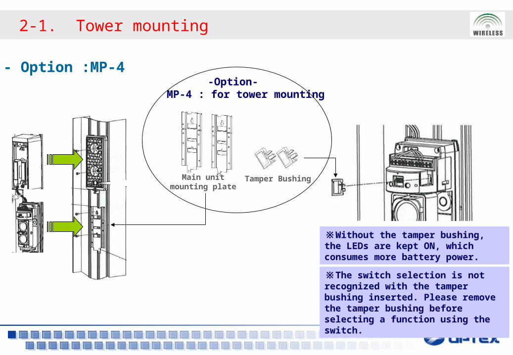
2-1. Tower mounting
- Option :MP-4
※The switch selection is not recognized with the tamper bushing inserted. Please remove the tamper bushing before selecting a function using the switch.
Main unit mounting plate
Tamper Bushing
-Option- MP-4 : for tower mounting
※Without the tamper bushing, the LEDs are kept ON, which consumes more battery power.
3. Features
1. Multifunctional back box
2. Easy installation
3. Easy maintenance
4. High reliable tamper alarm5. Long battery life
6. Low battery output & LED indicator
7. Auxiliary Functions for Wireless Transmitters
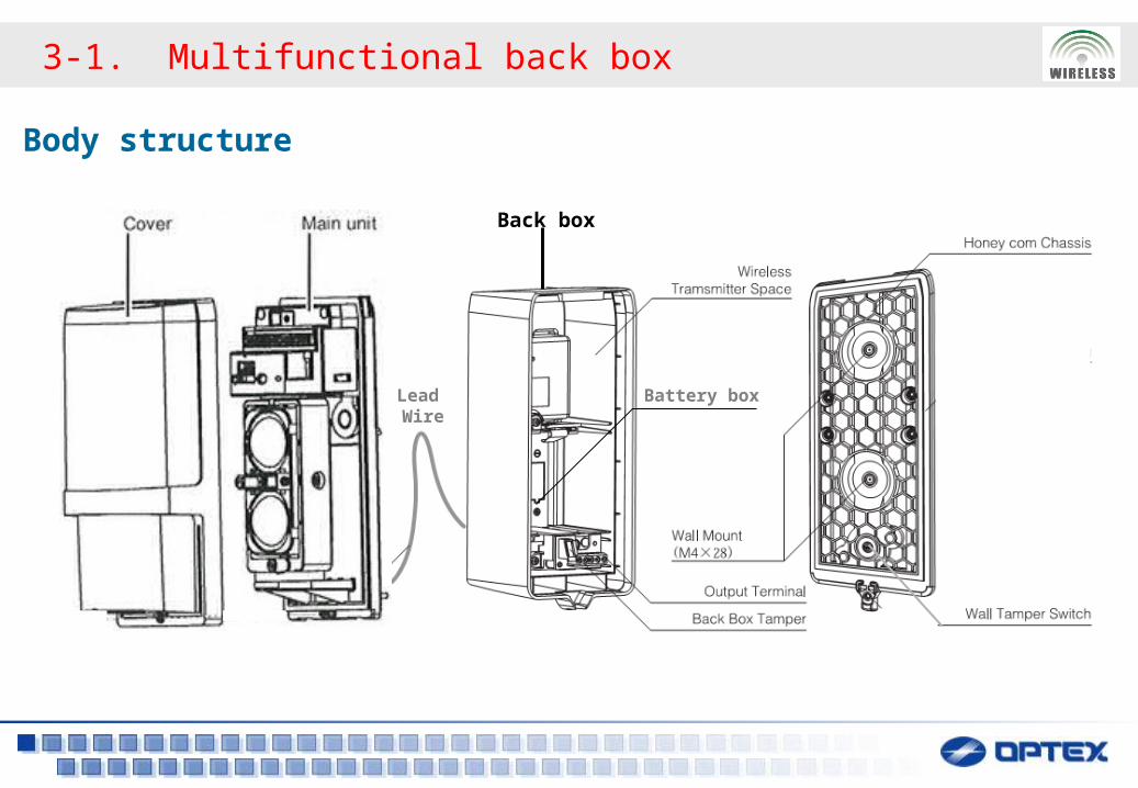
3-1. Multifunctional back box
Body structure
Lead Wire
Battery box
Back box
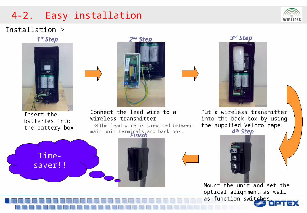
4-2. Easy installation
Insert the batteries into the battery box
1st Step 3rd Step
Put a wireless transmitter into the back box by using the supplied Velcro tape
2nd Step
Connect the lead wire to a wireless transmitter ※ The lead wire is prewired between main unit terminals and back box.
Finish4th Step
Mount the unit and set the optical alignment as well as function switches.
< Installation >
Time-saver!!
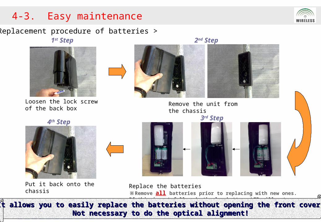
Loosen the lock screw of the back box
1st Step 2nd Step
Remove the unit from the chassis
3rd Step
Replace the batteries※Remove all batteries prior to replacing with new ones. If this is not followed, the low battery LED will not reset and continue to flicker.
4th Step
Put it back onto the chassis
4-3. Easy maintenance
< Replacement procedure of batteries >
It allows you to easily replace the batteries without opening the front cover!It allows you to easily replace the batteries without opening the front cover!Not necessary to do the optical alignment!Not necessary to do the optical alignment!
4-4. High reliable tamper alarm
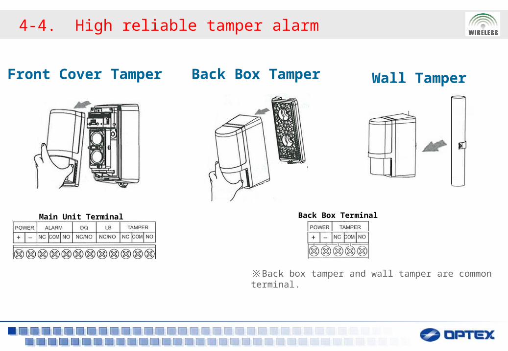
Front Cover Tamper Back Box Tamper Wall Tamper
※ Back box tamper and wall tamper are common terminal.
Main Unit Terminal Back Box Terminal
4-5. Long battery life
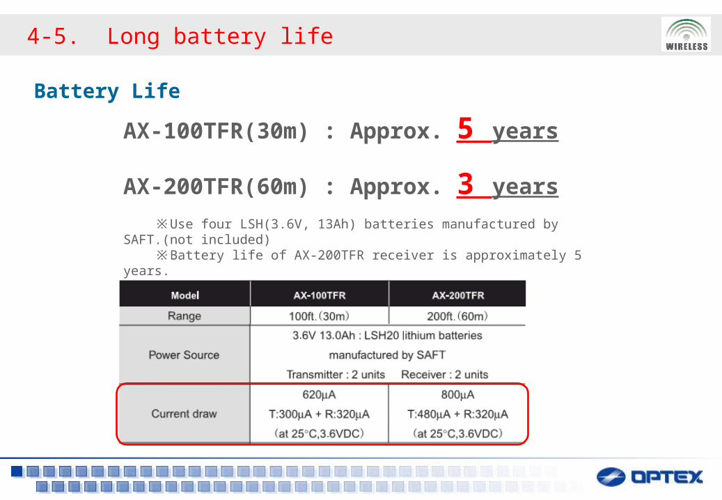
Battery Life
AX-100TFR(30m) : Approx. 5 years
AX-200TFR(60m) : Approx. 3 years
※Use four LSH(3.6V, 13Ah) batteries manufactured by SAFT.(not included) ※Battery life of AX-200TFR receiver is approximately 5 years.
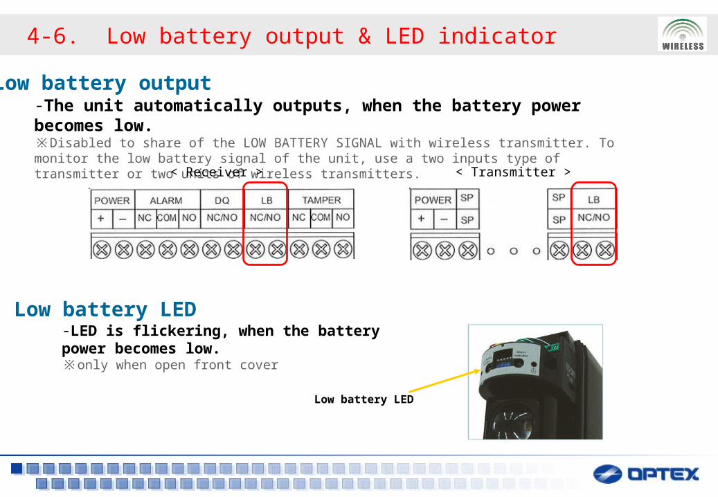
Low battery LED-LED is flickering, when the battery power becomes low.※ only when open front cover
Low battery output-The unit automatically outputs, when the battery power becomes low.※ Disabled to share of the LOW BATTERY SIGNAL with wireless transmitter. To monitor the low battery signal of the unit, use a two inputs type of transmitter or two units of wireless transmitters.
< Receiver >
Low battery LED
4-6. Low battery output & LED indicator
< Transmitter >
4-7. Auxiliary functions for wireless transmitters
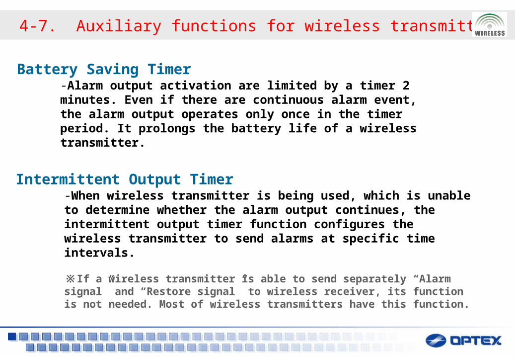
Battery Saving Timer-Alarm output activation are limited by a timer 2 minutes. Even if there are continuous alarm event, the alarm output operates only once in the timer period. It prolongs the battery life of a wireless transmitter.
Intermittent Output Timer-When wireless transmitter is being used, which is unable to determine whether the alarm output continues, the intermittent output timer function configures the wireless transmitter to send alarms at specific time intervals.
※If a wireless transmitter is able to send separately “Alarm signal” and “Restore signal” to wireless receiver, its function is not needed. Most of wireless transmitters have this function.
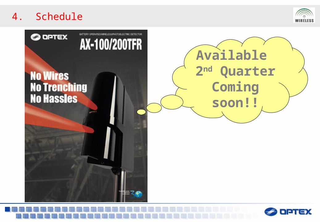
4. Schedule
Available 2nd Quarter
Coming soon!!

Thank you
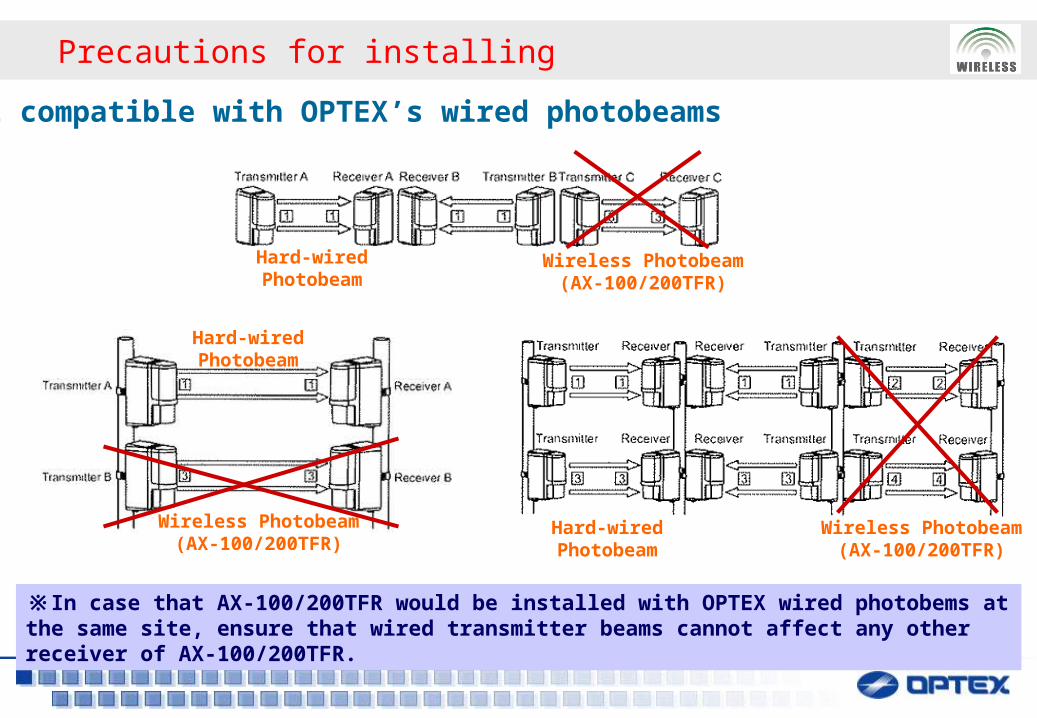
Precautions for installing
Not compatible with OPTEX’s wired photobeams
Hard-wiredPhotobeam
Wireless Photobeam(AX-100/200TFR)
Hard-wiredPhotobeam
Wireless Photobeam(AX-100/200TFR)
※In case that AX-100/200TFR would be installed with OPTEX wired photobems at the same site, ensure that wired transmitter beams cannot affect any other receiver of AX-100/200TFR.
Hard-wiredPhotobeam
Wireless Photobeam(AX-100/200TFR)


![PLAN DE ORDENAMIENTO TERRITORIAL SESION …adn.gob.do/pot/2-DOCUMENTOS-BASE/2.7-[DN]-Insumos... · Frente costero-marino 60M (No Urbanizable) Ley 305-68 30M libres a ambos lados Perímetro](https://img.pdfslide.us/doc/110x75/5e3afb379ea02978b2105e95/plan-de-ordenamiento-territorial-sesion-adngobdopot2-documentos-base27-dn-insumos.jpg)