Embed Size (px)
Citation preview

ProXW Pro 8548
Owner's Guide990-91402B
February 2021
https://solar.schneider-electric.com
Copyright © 2021 Schneider Electric. All Rights Reserved.
Trademarks are owned by Schneider Electric Industries SAS or its affiliated companies. Other trademarks are owned bytheir respective companies.
Exclusion for Documentation
UNLESSSPECIFICALLYAGREED TO INWRITING, SELLER
(A) MAKESNOWARRANTYASTOTHEACCURACY, SUFFICIENCYOR SUITABILITYOF ANYTECHNICALOROTHER INFORMATION
PROVIDED IN ITSMANUALSOROTHER DOCUMENTATION;
(B) ASSUMESNORESPONSIBILITYOR LIABILITYFOR LOSSES, DAMAGES, COSTSOR EXPENSES,WHETHER SPECIAL, DIRECT,
INDIRECT, CONSEQUENTIALOR INCIDENTAL,WHICHMIGHT ARISEOUT OF THEUSEOF SUCH INFORMATION. THEUSEOF ANYSUCH
INFORMATIONWILL BEENTIRELYAT THEUSER’SRISK; AND
(C) REMINDSYOU THAT IF THISMANUAL IS IN ANYLANGUAGEOTHER THAN ENGLISH, ALTHOUGH STEPSHAVEBEEN TAKEN TO
MAINTAIN THEACCURACYOF THETRANSLATION, THEACCURACYCANNOT BEGUARANTEED. APPROVED CONTENT ISCONTAINED
WITH THEENGLISH LANGUAGEVERSIONWHICH ISPOSTED AT https://solar.schneider-electric.com.
Document Number: 990-91402B Date: February 2021Model Name: XW Pro 8548
Product Part Number: 865-8548-55
Contact Information
For country-specific details, please contact your local Schneider Electric Sales Representative or visit the SchneiderElectric Solar Business website at: https://solar.schneider-electric.com
Information About Your System
As soon as you open your product, record the following information and be sure to keep your proof of purchase.
Serial Number ____________________________
Product Number ____________________________
Purchased From ____________________________
Purchase Date ____________________________
READ AND SAVE THESE INSTRUCTIONSSafety InformationImportant Information
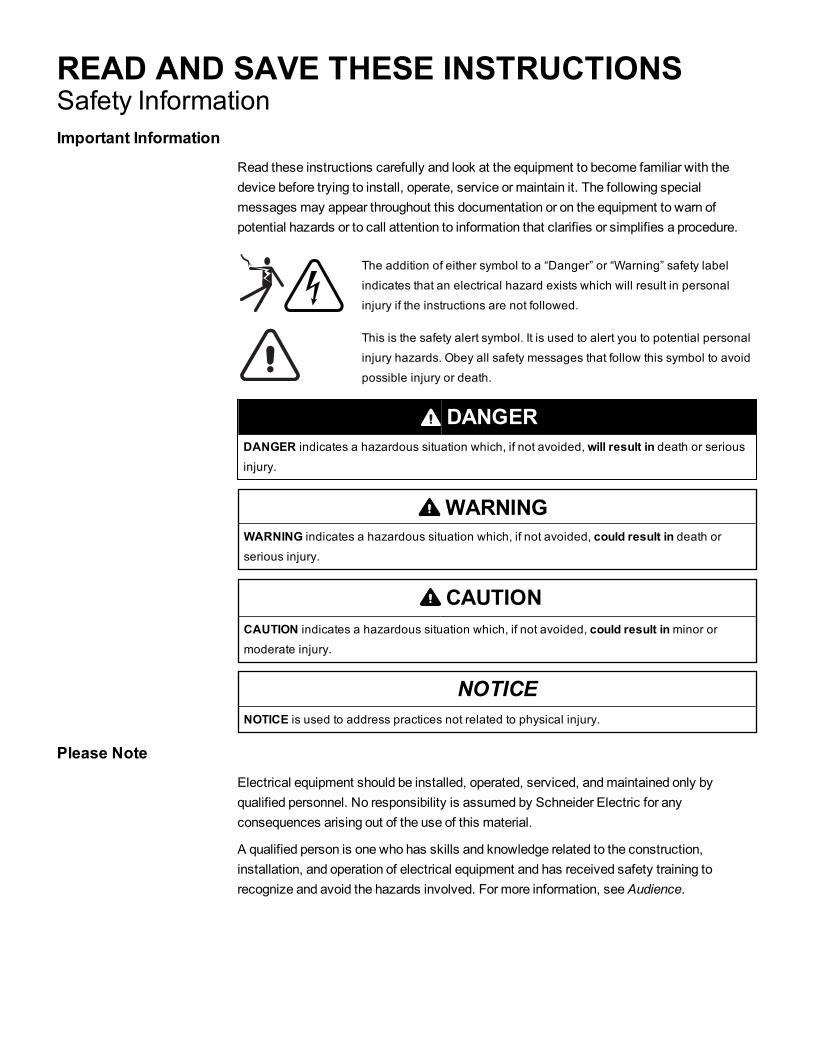
Read these instructions carefully and look at the equipment to become familiar with thedevice before trying to install, operate, service or maintain it. The following specialmessages may appear throughout this documentation or on the equipment to warn ofpotential hazards or to call attention to information that clarifies or simplifies a procedure.
The addition of either symbol to a “Danger” or “Warning” safety labelindicates that an electrical hazard exists which will result in personalinjury if the instructions are not followed.
This is the safety alert symbol. It is used to alert you to potential personalinjury hazards. Obey all safety messages that follow this symbol to avoidpossible injury or death.
DANGERDANGER indicates a hazardous situation which, if not avoided,will result in death or seriousinjury.
WARNINGWARNING indicates a hazardous situation which, if not avoided, could result in death orserious injury.
CAUTIONCAUTION indicates a hazardous situation which, if not avoided, could result inminor ormoderate injury.
NOTICENOTICE is used to address practices not related to physical injury.
Please NoteElectrical equipment should be installed, operated, serviced, andmaintained only byqualified personnel. No responsibility is assumed by Schneider Electric for anyconsequences arising out of the use of this material.
A qualified person is one who has skills and knowledge related to the construction,installation, and operation of electrical equipment and has received safety training torecognize and avoid the hazards involved. For more information, seeAudience.
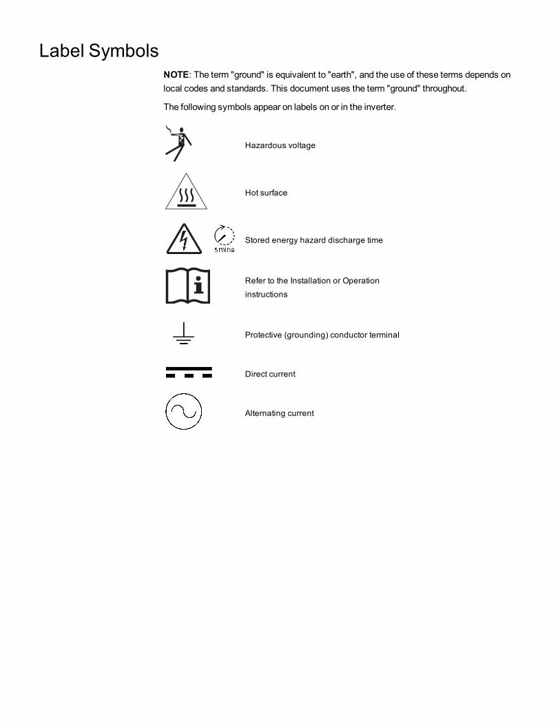
Label SymbolsNOTE: The term "ground" is equivalent to "earth", and the use of these terms depends onlocal codes and standards. This document uses the term "ground" throughout.
The following symbols appear on labels on or in the inverter.
Hazardous voltage
Hot surface
Stored energy hazard discharge time
Refer to the Installation or Operationinstructions
Protective (grounding) conductor terminal
Direct current
Alternating current
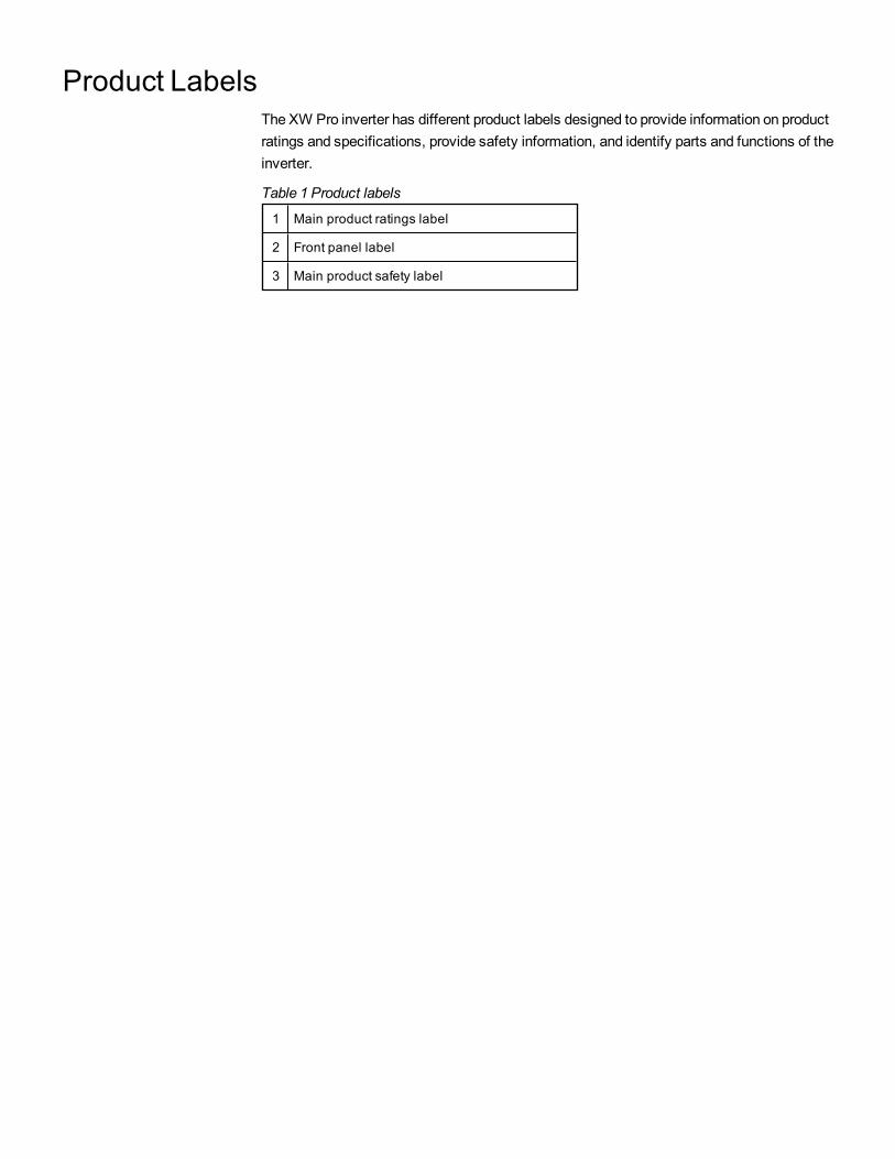
Product LabelsThe XW Pro inverter has different product labels designed to provide information on productratings and specifications, provide safety information, and identify parts and functions of theinverter.
1 Main product ratings label
2 Front panel label
3 Main product safety label
Table 1 Product labels

Main Product Ratings LabelThemain product ratings label contains the inverter's product ratings and technicalspecifications. Do not remove, cover, deface, or alter the main product label. Alocalizedmain product label is available to install on the product.
Figure 1 Main product ratings label example
NOTE: This is for illustration purposes only. Actual ratings vary for eachmodel.
1 Name of the product and model number
2 Charger ratings
3 Inverter ratings
4 Product part number and operating temperature range
5 Product serial number information
6 Product date of manufacture information
7 Regulatory markings
8 Enclosure rating

Front Panel LabelThe front panel label contains the LCD display and LED indicators. It also identifies thevarious buttons used in inverter operation. For information on the indicators and controlbutton, see the Figure 9 on page 29.
Figure 2 Inverter Information Panel
Main Product Safety LabelThemain product safety label is themain safety label for the inverter which lists generalhazards and instructions on avoiding them. The label is applied on the exterior of theinverter.
Do not remove, cover, deface, or alter the main product safety label. A localized labelis available to install on the product.
For information on the symbols appearing in the label, see Label Symbols on page 4.
Other Safety LabelsOther safety labels appear onmany areas of the equipment to warn of potential hazardswithin those areas of the inverter or to call attention to information that clarifies or simplifiesa procedure. Read and follow all safety labels before proceeding.
Do not remove, cover, deface, or alter safety labels. Localized safety labels areavailable to install on the product.
For information on the symbols appearing in the label, see Label Symbols on page 4.
AudienceThis guide is intended for use by anyone needs to operate, configure, and troubleshoot theXW Pro inverter/charger. Certain configuration tasks should only be performed by qualifiedpersonnel in consultation with your local utility and/or an authorized dealer. Electricalequipment should be installed, operated, serviced, andmaintained only by qualifiedpersonnel. Keep unqualified personnel away from batteries. Servicing of batteries must onlybe performed or supervised by qualified personnel with knowledge of batteries and theirrequired precautions. Qualified personnel have training, knowledge, and experience in
n Installing electrical equipment.
n Applying all applicable installation codes.
n Analyzing and reducing the hazards involved in performing electrical work.
n Installing and configuring batteries.
n Selecting and using Personal Protective Equipment (PPE).
This guide does not contain information regarding servicing or de-energization for servicing.No responsibility is assumed by Schneider Electric for any consequences arising out of theuse of this material.

About
PurposeThis guide provides explanations and procedures for operating the Schneider Electric XWPro inverter/charger.
n Installation instructions are available in theXW Pro Installation Guide (documentnumber 990-91403)
n Instructions for configuring inverter settings are available in this guide.
For explanations and procedures related to other products, please contact themanufacturerof those products.
ScopeThis guide provides safety guidelines and information about operating the XW Proinverter/charger.
TheOwner's Guide provides safety guidelines and information about operating the XW Proinverter/charger and related system components. It does not provide details aboutinstallation, maintenance, or servicing. See theOperation Guide or Owner’s Guide of eachdevice for this information. This Owner's Guide does not provide details about particularbrands of batteries, photoelectric cells, or generators. Consult individual batterymanufacturers for this information.
Abbreviations and AcronymsGT Grid Tie
IEC InternationalElectrotechnicalCommission
LCD Liquid CrystalDisplay
LED Light Emitting Diode
MPPT MaximumPower Point Tracking
PV Photovoltaic
PVGFP PVGround Fault Protection
VAC VoltsAlternating Current
VDC VoltsDirect Current

Related InformationFindmore information about Schneider Electric, as well as its products and services at:www.schneider-electric.com.
For specific information about Schneider Electric Solar products, visit:https://solar.schneider-electric.com.
For available accessories, see the XW Pro Installation Guide (document number 990-91403).

Product Safety InformationIMPORTANT: Remember to read and follow all product safety information in thisdocument.
General Safety InstructionsBefore using the inverter/charger, read all instructions and cautionary markings on theunit, the batteries, and all appropriate sections of this manual.
n Use of accessories not recommended or sold by themanufacturer may result in a riskof fire, electric shock, or injury to persons.
n The inverter/charger is designed to be permanently connected to your AC and DCelectrical systems. Themanufacturer recommends that all wiring be done by acertified technician or electrician to ensure adherence to the local and nationalelectrical codes applicable in your jurisdiction.
n To avoid a risk of fire and electric shock, make sure that existing wiring is in goodcondition and that wire is not undersized. Do not operate the inverter/charger withdamaged or substandard wiring.
n Do not operate the inverter/charger if it has been damaged in any way.
n Most of the parts in this unit are not user-serviceable parts.Do not disassemble theinverter/charger except where noted for connecting wiring and cabling. See yourwarranty for instructions on obtaining service. Attempting to service the unit yourselfmay result in a risk of electrical shock or fire. Internal capacitors remain charged afterall power is disconnected.
n To reduce the risk of electrical shock, disconnect both AC and DC power from theinverter/charger before attempting any maintenance or cleaning or working on anycomponents connected to the inverter/charger. Putting the unit in Standby mode willnot reduce this risk.
n The inverter/charger must be provided with an equipment-grounding conductorconnected to the AC input ground.
n Do not expose this unit to rain, snow, or liquids of any type. This product is designedfor indoor use only. Damp environments will significantly shorten the life of thisproduct and corrosion caused by dampness will not be covered by the productwarranty.
n To reduce the chance of short-circuits, always use insulated tools when installing orworking with this equipment.
n Remove personal metal items such as rings, bracelets, necklaces, and watcheswhen working with electrical equipment.
n Do not expose this unit to excessive shock or vibration. This product is designed forstationary indoor use only. Mechanical fatigue caused by excessive shock orvibration can significantly shorten the life of this product and will not be covered bythe product warranty.
Product Safety Information XW Pro Owner's Guide
990-91402B This document is intended for use by qualified personnel 11
DANGERHAZARD OF ELECTRIC SHOCK, EXPLOSION, ARC FLASH, AND FIRE
This document is in addition to, and incorporates by reference, the relevant productmanuals for XW Pro inverter/charger. Before reviewing this document, you must read therelevant product manuals. Unless specified, information on safety, specifications,installation and operation is as shown in the primary documentation received with theproduct. Ensure you are familiar with that information before proceeding.
Failure to follow these instructions will result in death or serious injury.
DANGERHAZARD OF ELECTRIC SHOCK, EXPLOSION, ARC FLASH, AND FIRE
n Apply appropriate personal protective equipment (PPE) and follow safe electrical workpractices. Refer to EN 50110 or other regional safety standards.
n This equipment must only be installed and serviced by qualified electrical personnel.
n Never operate energized with covers removed
n Energized from multiple sources. Before removing covers identify all sources, de-energize, lock-out, and tag-out and wait 5 minutes for circuits to discharge
n Always use a properly rated voltage sensing device to confirm all circuits are de-energized.
Failure to follow these instructions will result in death or serious injury.
DANGERHAZARD OF ELECTRIC SHOCK, EXPLOSION, ARC FLASH, AND FIRE
n Disconnect negative and positive DC conductors before servicing. DC conductors are tobe treated as Hazardous Live and must be disconnected.
n Normally GROUNDED conductors may be UNGROUNDED and ENERGIZED when aGROUND FAULT is indicated on the front panel. Must be serviced by qualifiedpersonnel.
Failure to follow these instructions will result in death or serious injury.
XW Pro Owner's Guide Product Safety Information
12 This document is intended for use by qualified personnel 990-91402B

Precautions when Working with BatteriesNOTE: Battery work and maintenance must be done by qualified personnel knowledgeableabout batteries to help ensure compliance with battery handling and maintenance safetyprecautions.
DANGERHAZARD OF ELECTRIC SHOCK, EXPLOSION, OR ARC FLASH
n Remove watches, rings, or other metal objects.
n This equipment must only be installed and serviced by qualified electrical personnel.
n Keep sparks and flames away from the batteries.
n Use tools with insulated handles.
n Wear protective glasses, gloves and boots.
n Do not lay tools or other metal parts on top of batteries.
Failure to follow these instructions will result in death or serious injury.
DANGERHAZARD OF ELECTRICAL SHOCK, EXPLOSION, OR FIRE
n Battery Circuit Breakers must be installed according to the specifications andrequirements defined by Schneider Electric.
n Servicing of batteries must only be performed by qualified personnel knowledgeableabout batteries and the required precautions. Keep unqualified personnel away frombatteries.
n Disconnect the charging source prior to connecting or disconnecting battery terminals.
Failure to follow these instructions will result in death or serious injury.
Limitations on Use
WARNINGHAZARD DUE TO UNINTENDED USE
The XW Pro inverter is not intended for use in connection with life support systems or othermedical equipment or devices. The XW Pro inverter can only be used in grid-interconnected, off grid, and integrated PV systems. It is not suitable for any otherapplication areas.
Failure to follow these instructions can result in death, serious injury, or equipmentdamage.
Product Safety Information XW Pro Owner's Guide
990-91402B This document is intended for use by qualified personnel 13
Explosive Gas Precautions
WARNINGEXPLOSION HAZARD
The XW Pro is not ignition protected. To prevent fire or explosion, do not install this productin locations that require ignition-protected equipment. This includes any space containinggasoline-powered machinery, fuel tanks, as well as joints, fittings, or other connectionsbetween components of the fuel system.
Failure to follow these instructions can result in death, serious injury, or equipmentdamage.
Working in the vicinity of lead acid batteries is dangerous. Batteries generate explosivegases during normal operation. Therefore, youmust read this Owner's Guide and followthe instructions exactly before installing or using your inverter/charger.
To reduce the risk of battery explosion, follow these instructions and those published bythe battery manufacturer and themanufacturer of the equipment in which the battery isinstalled.
MaintenanceThe XW Pro does not require scheduledmaintenance. However it is required to be clearof dust and debris, especially around air intake and exhaust areas, at all times. Use asoft-bristle brush to clear the area around the air intake and exhaust.
The surface of XW Pro can be cleaned by using a lint-free soft cloth.
NOTICESTATEMENT OF HAZARD
Use only a soft cloth dampened with water and mild soap to clean theinverter.
Do not use solvents or chemicals that are corrosive or flammable.
Failure to follow these instructions can result in equipment damage.
XW Pro Owner's Guide Product Safety Information
14 This document is intended for use by qualified personnel 990-91402B
ContentsSafety Information 3Label Symbols 4Product Labels 5Audience 8About 9
Purpose 9Scope 9Abbreviations and Acronyms 9Related Information 10
Product Safety Information 11General Safety Instructions 11
Precautions whenWorking with Batteries 13Limitations on Use 13Explosive Gas Precautions 14Maintenance 14
Introduction 19Features 20
Performance Highlights 20Distinguishing Features 20Available XW Pro Accessories 21Regulatory Certification 21
Operation 22Bidirectional Theory of Operation 22Surge Performance 25Islanding Protection 25AC Coupling 26Multi-unit Operation 27Auxiliary Output 28Transfer Relays 28
Monitoring the XW Pro 29XW Pro Information Panel 29Conext Gateway 30Conext Configuration Tool 30
Monitoring Operation 31Monitoring Operation with the Inverter Information Panel 32
Monitoring AC Input Status 33Monitoring XW Pro Status 33Monitoring Charger Status 34Monitoring Events 34Equalizing Batteries 34Using Startup/Shutdown/Standby Modes 36Monitoring Battery Level 38
XW Pro Owner's Guide
990-91402B This document is intended for use by qualified personnel 15
Reading the Display Screen 39Monitoring Operation with the Conext Gateway 39
Accessing the Device in theWeb Application 39Status Page 39Performance Page 42Events Page 43
External Monitoring Control 45Overview 46SunSpec Modbus 46
Power Limiting 46Communications Loss 46
IEEE2030.5 47DemandResponseMode 0 (DRM0) 47
Configuration 49Configuration with the Conext Gateway Web Application 50
Accessing theWeb Application 50Setting the Device Name 51Setting the Device Number 51Setting the Time and Date 52
XW Pro Configuration Page 52Controls Settings 52Inverter Settings 53Charger Settings 57AC Settings 69Grid Support Settings 73Generator Support Settings 77Auxiliary Output Settings 79Multi-Unit ConfigurationMenu 82Associations Settings 84Advanced Features 85Advanced Device Settings 87Battery Management System Settings 88Device Instance Settings 90Modbus Settings 90
Prioritizing andManaging Energy Sources with Advanced Features 92Grid Support 92Charger Block 95Peak Load Shaving (PLS) 95
Managing Firmware 98Managing Compliance Regions 99
Grid Support Utility Interactive Functions 100AS/NZS 4777.2-2015 Australia 102
Resetting the XW Pro to Default Settings 111Troubleshooting 113
XW Pro Owner's Guide
16 This document is intended for use by qualified personnel 990-91402B

General Troubleshooting Guidelines 114Inverter Applications 115
Resistive Loads 115Motor Loads 115Problem Loads 115
Inverter Troubleshooting 117Battery Charger Troubleshooting 120Faults andWarnings 122
WarningMessages 122Fault Messages 125
Specifications 135Appendix A: Specifications 136
Electrical Specifications 136Mechanical and Regulatory Specifications 138
XW ProOverload Capability 140Output Power Versus Ambient Temperature 141XW Pro Efficiency 142
Defaults 145Default Settings 146
XW Pro Owner's Guide
990-91402B This document is intended for use by qualified personnel 17

Introduction1
Features 20Performance Highlights 20Distinguishing Features 20Available XW Pro Accessories 21Regulatory Certification 21
Operation 22Bidirectional Theory of Operation 22Surge Performance 25Islanding Protection 25AC Coupling 26Multi-unit Operation 27Auxiliary Output 28Transfer Relays 28
Monitoring the XW Pro 29XW Pro Information Panel 29Conext Gateway 30Conext Configuration Tool 30
What's in This Chapter?
FeaturesThe XW Pro is amodular building block sine-wave inverter/charger that can be used forresidential and commercial battery based off-grid, grid backup, and grid interactiveapplications.
The XW Pro is a self-contained DC to AC inverter, battery charger, and integrated ACtransfer switch. It is configurable in a hybrid system to operate with generators andrenewable energy sources. These configurations are capable of extending battery basedoff-grid/backup autonomy.
Performance Highlightsn High-capacity motor load starting with high 30-minute and 5-second power.
n Off-grid AC Coupling with PV inverters using frequency power curtailment method.
n Operation in hot environments up to 40°C without derating.
n Conversion of DC energy to AC energy for export to the utility grid.
n Power factor corrected chargingminimizes AC current required for charging.
n Very low distortion sine wave output.
Distinguishing Featuresn Grid-interactive feature set enables timemanagement and prioritization of energy
sources and power conversion to support advancedmodes of operation such as loadshifting, self consumption and peak load shaving.
n Dual AC input connections with 60 A automatic transfer switch integrates both utilitygrid and generator.
n Generator Support functionality assists small generators with heavy loads.
n Auxiliary port assist with relay switching of external devices such as battery roomfans, diversion loads and generators.
n Configurable battery parameters for customized battery charging.
n Field serviceable boards and components.
Xanbus™ Network Communications ProtocolThe XW Pro uses Xanbus™, a network communications protocol developed bySchneider to communicate with other Xanbus-enabled devices. You can configure andmonitor the XW Pro and other Xanbus-enabled devices in the system using the ConextGateway (part number 865-0329).
XW Pro Owner's Guide Introduction
20 This document is intended for use by qualified personnel 990-91402B

Available XW Pro AccessoriesAccessory Part Number
XW Pro Power Distribution Panel 865-1015-01
XW Pro Power Distribution Panel (Without AC Breakers) 865-1014-01
XW Pro Conduit Box 865-1025-01
Conext Gateway 865-0329
Conext Configuration Tool 865-1155-01
Conext AGS Automatic Generator Start 865-1060-01
Conext MPPT solar charge controller MPPT 60 150 865-1030-1
Conext MPPT solar charge controller MPPT 80 600 865-1032
Conext Battery Monitor 865-1080-01
Conext Response (dongle for DRM feature) 865-1170
Regulatory CertificationSeeMechanical and Regulatory Specifications on page 138
Introduction XW Pro Owner's Guide
990-91402B This document is intended for use by qualified personnel 21

Operation
Bidirectional Theory of Operation
NOTICEEQUIPMENT DAMAGE
n The Automatic Transfer Relays are rated at 60 A.
n Loads connected at AC OUTmust not exceed the inverter's overload ratings or the 60 Alimit, whichever is lower. Unless an external contactor or external transfer switch isused, the 60 A limit also applies to loads connected to the AC OUT bus of multipleinverters connected in parallel.
Failure to follow these instructions can result in equipment damage.
The XW Pro is a grid forming device consisting of a bidirectional inverter/charger. It iscapable of inverting DC power into AC power and controlling the voltage and frequency ofits inverter output. It will power external loads attached to AC OUT, see Figure 4 on page23.
The XW Pro is also capable of charging external batteries by converting AC power intoDC power, see Figure 5 on page 23. The XW Pro accepts AC power through connectionAC2 for charging batteries, usually from a generator, see Figure 6 on page 24.
The XW Pro will convert externally sourced DC power into AC power for export to theutility grid attached to its AC1 connection, see Figure 7 on page 24.
The XW Pro has internal automatic transfer switches (K1, K2), rated at 60 A, which alloweither AC1 or AC2 to be connected to the inverter input, but not both at the same time,see Figure 3 on page 23. This allows shared AC energy during charging or to directlypassthrough from AC1, or AC2, to AC Out.
Through firmware control over power conversion and themanagement of K1 and K2, XWPro can facilitate advanced interaction with the utility grid to optimize the utilization ofrenewable and non-renewable energy sources. Because the XW Pro is a device capableof forming an AC grid signal (AC voltage and frequency) it is also ideal for use off-grid.
The red arrows in the diagrams below represent the direction of power flow in therespectivemodes of operation. Thesemodes and other special functions will beexplained throughout this manual.
XW Pro Owner's Guide Introduction
22 This document is intended for use by qualified personnel 990-91402B
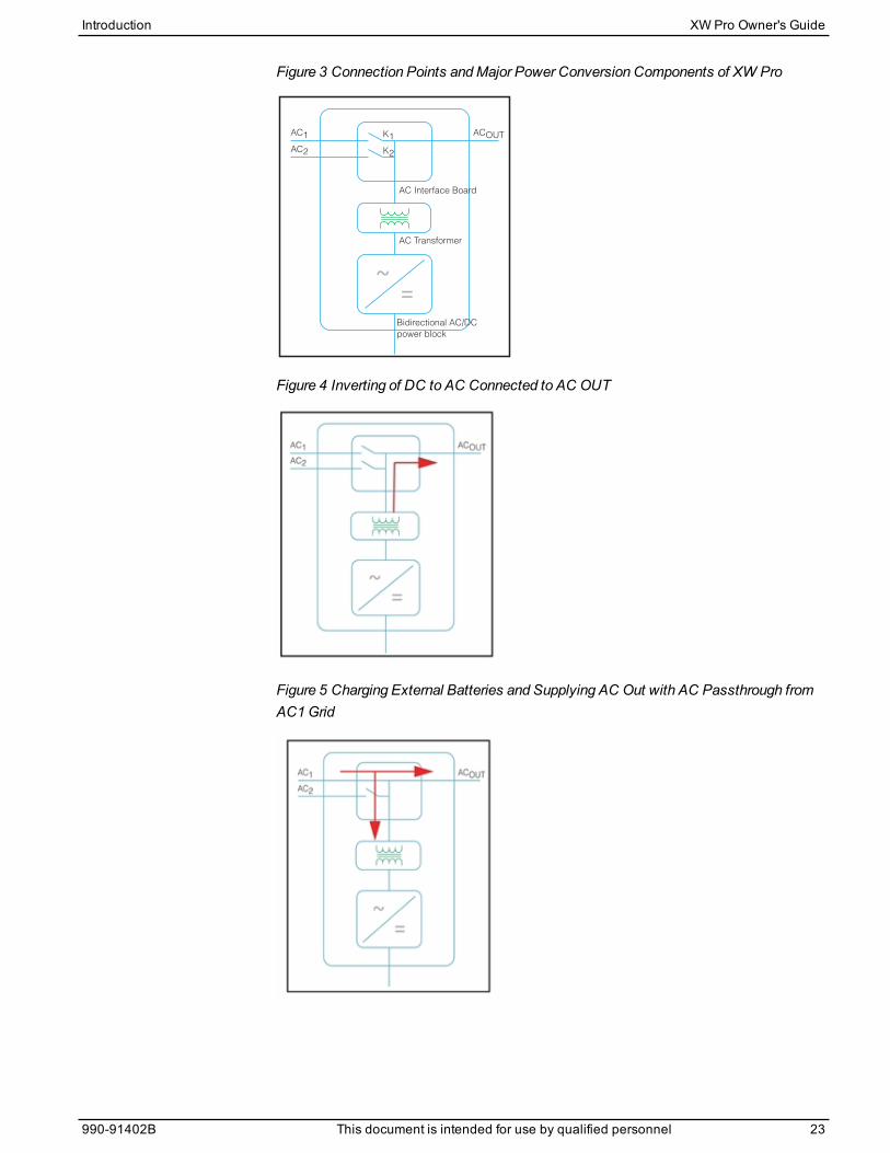
Figure 3 Connection Points andMajor Power Conversion Components of XW Pro
K2
K1
AC Transformer
Bidirectional AC/DC
power block
AC Interface Board
AC1
AC2
ACOUT
Figure 4 Inverting of DC to AC Connected to AC OUT
Figure 5 Charging External Batteries and Supplying AC Out with AC Passthrough fromAC1Grid
Introduction XW Pro Owner's Guide
990-91402B This document is intended for use by qualified personnel 23
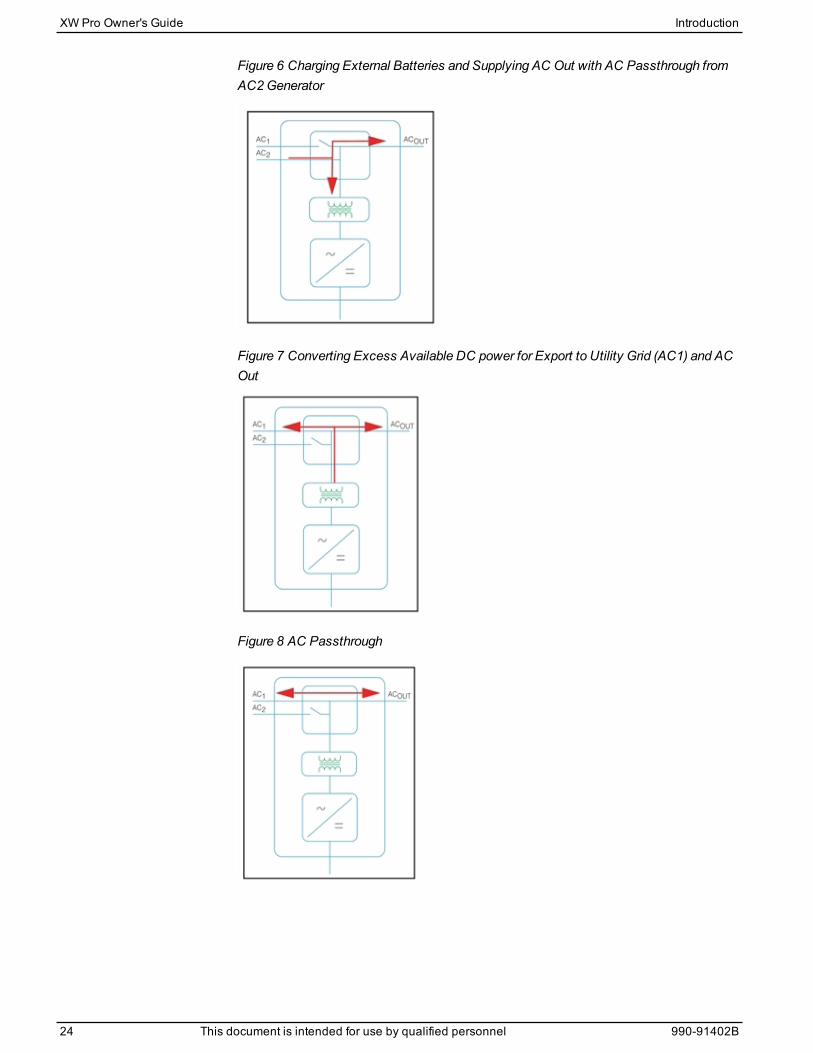
Figure 6 Charging External Batteries and Supplying AC Out with AC Passthrough fromAC2Generator
Figure 7 Converting Excess Available DC power for Export to Utility Grid (AC1) and ACOut
Figure 8 AC Passthrough
XW Pro Owner's Guide Introduction
24 This document is intended for use by qualified personnel 990-91402B
Surge PerformanceUnlikemany other inverters, the XW Pro helps stop voltage from sagging dramaticallyduring surge conditions. The XW Pro handles surges of over twice its rated output powerwith only aminimal drop in output voltage for limited periods of time.
Islanding ProtectionIslanding protection is an essential safety feature that helps reduce harm to thoseworking on the utility grid from a distributed energy source such as the XW Pro. Islandingprotection also helps to prevent loads connected to the XW Pro from being damaged by afluctuating utility grid input. The XW Pro uses proprietary positive feedback control toachieve anti-islanding operation while maintaining low total harmonic distortion at the gridconnection. Default software settings are programmed into each XW Pro at the factoryso that they comply with applicable safety regulations (such as IEC/EN 62116 (for IEC,EU and Australia regions)).
In some instances it may be desirable from both a utility and a customer point of view toadjust the default anti-islanding settings. For example, the XW Promay experience“nuisance trips” if the grid is weak and the voltage falls outside the allowable rangespecified by regulations. It may be difficult for a utility to adjust the grid to stop thisproblem. With permission from the utility, the factory settings may be changed to allowthe XW Pro to operate over a wider grid voltage range. These settings must only bechanged by qualified service personnel using either Conext Gateway or a specialsoftware application (XW Pro Configuration Tool, Order # 865-1155-01) provided by themanufacturer.
While exporting energy, the XW Pro continuously monitors the utility grid voltage andfrequency. If the grid voltage or frequency move beyond the XW Pro default ranges (forexample, during a power surge or outage) the XW Pro stops exporting energy throughAC1 and disconnects from the utility. If disconnected due to a grid voltage disturbance,oneminute is the non-adjustable minimum reconnect time during which the XW Pro doesnot export energy through AC1 to the grid. The Event LED on the XW Pro informationpanel will indicate a utility fault. No fault code appears on the three-character displaybecause the fault is with the utility grid, not with the XW Pro.
In addition to the information panel, the Conext Gateway web application indicates anyutility faults with details present under all affected instances of XW Pro. The faultscannot bemanually cleared. Utility faults will clear automatically when the utility gridvoltage and frequency return to within the ranges programmed into the XW Pro. If gridsupport is enabled and the utility voltage and frequency come back within tolerance, theXW Pro information panel displays a countdown timer for oneminute until the XW Procan start interacting with the grid again.
Introduction XW Pro Owner's Guide
990-91402B This document is intended for use by qualified personnel 25
AC CouplingOff-grid AC Coupled system architecture is often used to create a stand-alone grid.Commonly this means that PV inverters are connected to the output of a battery-basedinverter/charger putting both on the same AC bus along with the AC loads. In thisscenario, the battery powered inverter charger provides the necessary frequency andvoltage to enable the PV inverter to produce power. This type of systemmust be able tomaintain power generation in balance with power consumption at all times. If there ismore power being generated than can be consumed by the loads, power will flow to theinverter/charger and be converted to DC power which flows into the battery. Once thebattery reaches capacity, power generation by the PV inverter must be curtailed tomaintain the balance between generation and consumption. As the battery bank reachescapacity, XW Pro curtails PV inverter generation by raising the AC line frequencycausing compatible PV inverters to reduce their power output in an orderly manner. Thisis called Active Frequency Shift Power Curtailment. In some compliance regions, whenthe grid returns from an outage, XW Pro will cause any AC coupled PV inverter totransition offline via the samemechanism prior to grid reconnection.
During a grid outage even a homewith a grid-tie PV inverter system will be without powerbecause PV inverters cannot produce power without the presence of a reference voltageand frequency. To enable the PV inverter to provide power during a grid outage the XWPro is retrofitted in front of the PV inverter. The PV inverter is rewired from the gridconnection to a critical load (sub) panel and is AC Coupled to the XW Pro AC Outputport. When the grid is present, PV inverter power feeds the loads and any excess isexported by XW Pro to the grid using AC1 (where permitted by the local utility). During agrid outage, XW Pro anti-islanding protection helps to prevents power from beingexported to grid on AC1. XW Pro then uses Active Frequency Shift Power Curtailment toreduce the power output of compatible PV inverters, maintaining the balance ofgeneration and consumption.
Consult themanufacturer's specifications to determine if your PV inverter is compatiblewith Active Frequency Shift Power Curtailment. XW Pro AC coupling function is enabledby default (Advanced Features Menu).
NOTICEAC COUPLED PV INVERTER COMPATIBILITY
AC power generated by AC coupling PV inverters with XW Pro must be consumed by ACloads or used to charge batteries. As an alternative, the excess power produced from a PVinverter can be routed to dump loads. Do not AC couple PV inverters with the XW Pro thatare unable to reduce, derate or cease the excess PV inverter power in response to thechanges in AC line frequency controlled by the XW Pro. Consult the manufacturer'sspecifications of your PV inverter and confirm compatibility.
Failure to follow these instructions can result in equipment damage.
The AC coupling advanced setting should remain enabled except in cases when the DCvoltage level is allowed to have large variations and the line frequency needs to remainconstant.
XW Pro Owner's Guide Introduction
26 This document is intended for use by qualified personnel 990-91402B
Further details about AC Coupling can be found in the document AC Coupling ofInverters Solutions Guide (976-0240-01-01) available at http://solar.schneider-electric.com.
Multi-unit OperationImportant:An external transfer switchmay be required to protect the internal relays fromthe combined loads of the system. For more information, see the XW ProMulti-unitDesign Guide (990-91373).
Up to three XW Pro units can be installed together in a split phase configuration with theXW Pro PDP (Power Distribution Panel). The PDP is an ideal optional companion formanaging AC connections and integrating a battery bank and other DC connections.
Multiple XW Pro units and other Xanbus devices with common connections to batterybanks, PV arrays, the utility grid or a generator require programming duringcommissioning to enable correct operation.
Inverting
Formultiple units, themaster XW Pro synchronizes operation of other connected unitsusing the same Xanbus network. When AC loads are present, all units produce power.Refer to the XW ProMulti-unit Design Guide (990-91373) for total system surge ratings.
Parallel Charging
Multiple XW Pro units on the same Xanbus network synchronize their charging stages tohelp provide efficient charging of the battery bank. When a single unit transitions frombulk to absorption, so do all other units. In absorption, all units must complete theabsorption stage before any of them transition to the next stage. Note that units stopsharing charge current just before completing the bulk stage and only share charging loadduring the bulk stage.
Each XW Pro unit provides amaximum charging current set by the Max Charge Rate
setting. Themaximum current may be decreased, subject to the internal operatingtemperature.
When one or more Conext Solar Charge Controllers are installed and operating in thesystem, XW Pro units synchronize only their bulk charging stage with the chargecontrollers.
Note: Equalization is device specific. Only the device(s) on which equalization was initiatedwill perform the equalization. Other devices will stay in float or no-float depending on theirsettings.
AC Transfer
Multiple XW Pro units monitor each other to determine the quality of AC input. If AC inputis deemed to be bad by any of the paralleled units, no transfer to AC Out occurs and theAC LED continues to flash on each unit’s information panel until the AC is qualified by all.If the system was in passthrough and AC fails on any unit, all units transfer to invertsimultaneously.
Introduction XW Pro Owner's Guide
990-91402B This document is intended for use by qualified personnel 27

Faults
When the XW Pro detects a fault condition, the fault is displayed on the XW Pro. The XWPro also turns on the Event LED on the XW Pro and inverter information panel. A faultaffects the operation of the unit. See "Fault Types" on page 125 for an explanation of thedifferent fault types.
When a single XW Pro slave unit in amulti-unit system has a fault, only the affecteddevice shuts down.
When amaster unit has an invert mode fault that causes it to stop inverting, it isconsidered a system-wide fault and all units shut down. Invert mode faults on slave unitsonly shut down the affected slave unit.
All units shut downwhen there is a battery-related fault such as battery over-temperatureor over-voltage.
Independent Operation of Features
Each XW Pro grid-interactive feature (e.g. enhanced grid support, grid sell, load shaveand generator support) operates independently. This enables XW Pro units in amulti-unitsystem to be configured to perform multiple functions independently and allows greaterflexibility in operating the entire system.
Auxiliary OutputEach XW Pro has one programmable 12 V, 0.25 A auxiliary output that is able to run asmall fan or operate an external relay to perform other functions. Examples includeremotely starting a two-wire start generator in cases where the Xanbus-enabled XW ProAGS is not used, disconnecting external non-critical loads, or turning on a diversion loadfor battery voltage regulation. See "Auxiliary Output Settings" on page 79 for programingparameters.
Transfer RelaysThe built-in transfer relays, designated K1 and K2, are each is rated for 60 amps.Connected loads must not draw currents exceeding this.When an external AC source isdetected and qualified on either of the AC1 or AC2 inputs, the relay transfers loads fromthe XW Pro to the external power source, and then activates the battery charger. The XWPro design does not allow the K1 and K2 relays to close simultaneously. This designhelps stop the generator input (AC2) from back feeding to the utility grid (AC1). Multi-unitsystems of three or more require the use of an external AC contactor to manage the ACbus.
XW Pro Owner's Guide Introduction
28 This document is intended for use by qualified personnel 990-91402B
Monitoring the XW ProOperation of the XW Pro can bemonitored using the factory-installed inverter informationpanel or the optional Conext Gateway. To configure the XW Pro, operators must use theConext Gatewayand service personnel can use the Config Tool or Conext Gateway.
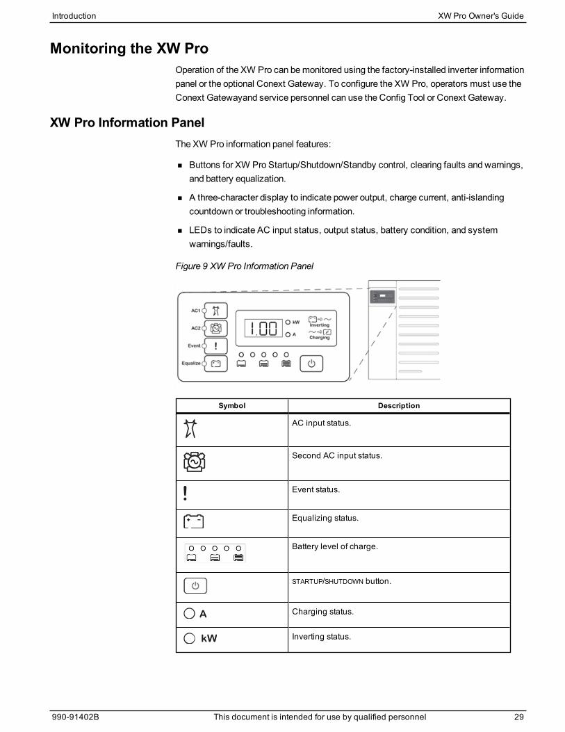
XW Pro Information PanelThe XW Pro information panel features:
n Buttons for XW Pro Startup/Shutdown/Standby control, clearing faults and warnings,and battery equalization.
n A three-character display to indicate power output, charge current, anti-islandingcountdown or troubleshooting information.
n LEDs to indicate AC input status, output status, battery condition, and systemwarnings/faults.
Figure 9 XW Pro Information Panel
Symbol Description
AC input status.
Second AC input status.
Event status.
Equalizing status.
Battery level of charge.
STARTUP/SHUTDOWN button.
Charging status.
Inverting status.
Introduction XW Pro Owner's Guide
990-91402B This document is intended for use by qualified personnel 29
Conext GatewayThe Conext Gateway is amulti-function communication device that provides an overallview of system performance for residential powermonitoring systems. It also provides acommunications gateway between a network of Xanbus™-enabled devices andModbusdevices, including third-party controllers. It is the primary tool for monitoring andconfiguring all Xanbus-enabled devices.
Conext Configuration ToolThe Conext Configuration Tool is used by system installers to simplify the task ofsystem configuration and reduce installation time. It is a PC-based software tool thatworks on Conext series devices and peripherals.
XW Pro Owner's Guide Introduction
30 This document is intended for use by qualified personnel 990-91402B

Monitoring Operation2
Monitoring Operation with the Inverter Information Panel 32Monitoring AC Input Status 33Monitoring XW Pro Status 33Monitoring Charger Status 34Monitoring Events 34Equalizing Batteries 34Using Startup/Shutdown/Standby Modes 36Monitoring Battery Level 38Reading the Display Screen 39
Monitoring Operation with the Conext Gateway 39Accessing the Device in theWeb Application 39Status Page 39Performance Page 42Events Page 43
What's in This Chapter?
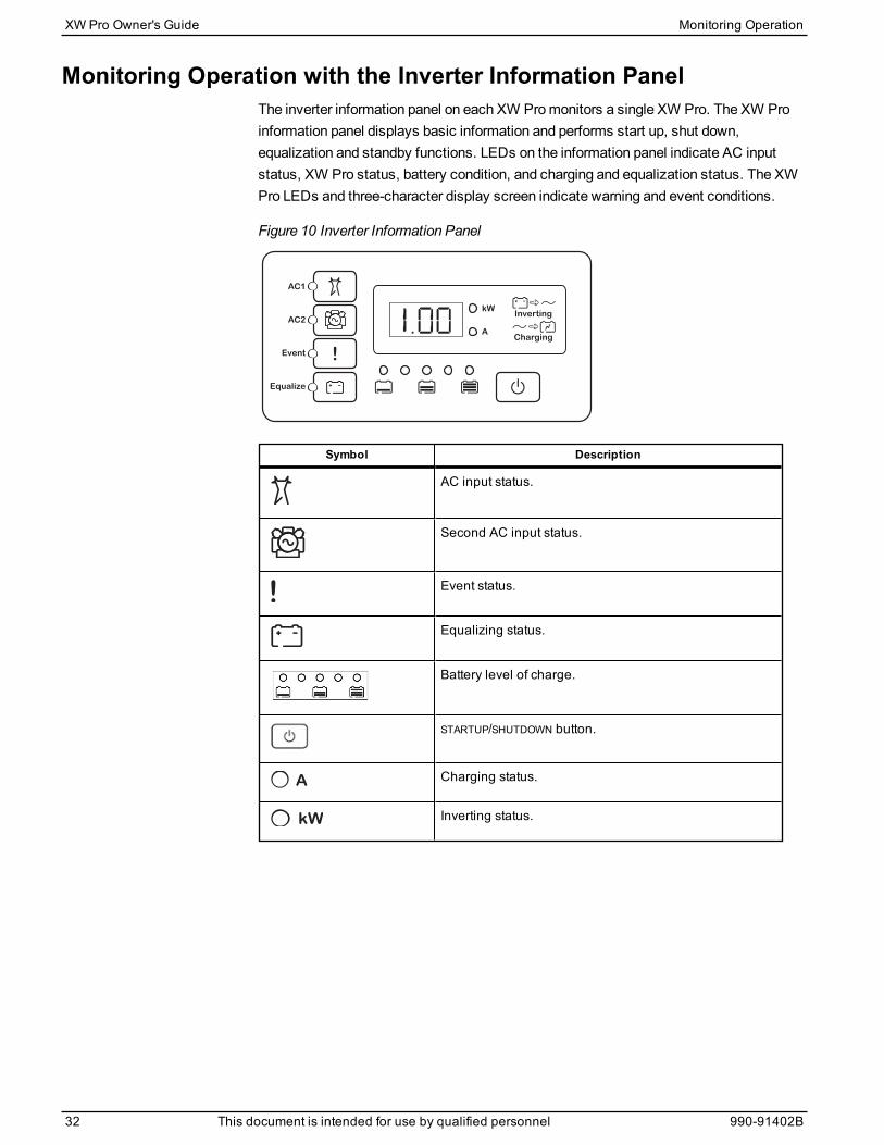
Monitoring Operation with the Inverter Information PanelThe inverter information panel on each XW Promonitors a single XW Pro. The XW Proinformation panel displays basic information and performs start up, shut down,equalization and standby functions. LEDs on the information panel indicate AC inputstatus, XW Pro status, battery condition, and charging and equalization status. The XWPro LEDs and three-character display screen indicate warning and event conditions.
Figure 10 Inverter Information Panel
Symbol Description
AC input status.
Second AC input status.
Event status.
Equalizing status.
Battery level of charge.
STARTUP/SHUTDOWN button.
Charging status.
Inverting status.
XW Pro Owner's Guide Monitoring Operation
32 This document is intended for use by qualified personnel 990-91402B
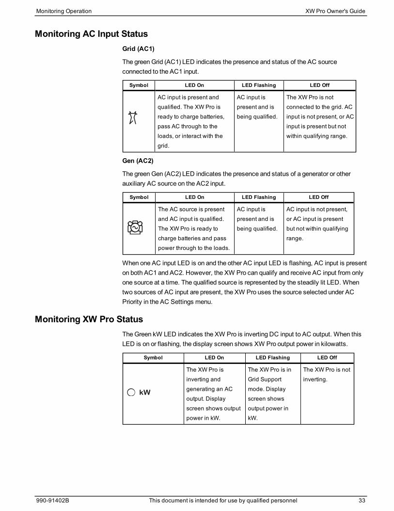
Monitoring AC Input StatusGrid (AC1)
The greenGrid (AC1) LED indicates the presence and status of the AC sourceconnected to the AC1 input.
Symbol LED On LED Flashing LED Off
AC input is present andqualified. The XW Pro isready to charge batteries,pass AC through to theloads, or interact with thegrid.
AC input ispresent and isbeing qualified.
The XW Pro is notconnected to the grid. ACinput is not present, or ACinput is present but notwithin qualifying range.
Gen (AC2)
The greenGen (AC2) LED indicates the presence and status of a generator or otherauxiliary AC source on the AC2 input.
Symbol LED On LED Flashing LED Off
The AC source is presentand AC input is qualified.The XW Pro is ready tocharge batteries and passpower through to the loads.
AC input ispresent and isbeing qualified.
AC input is not present,or AC input is presentbut not within qualifyingrange.
When one AC input LED is on and the other AC input LED is flashing, AC input is presenton both AC1 and AC2. However, the XW Pro can qualify and receive AC input from onlyone source at a time. The qualified source is represented by the steadily lit LED. Whentwo sources of AC input are present, the XW Pro uses the source selected under ACPriority in the AC Settings menu.
Monitoring XW Pro StatusTheGreen kW LED indicates the XW Pro is inverting DC input to AC output. When thisLED is on or flashing, the display screen shows XW Pro output power in kilowatts.
Symbol LED On LED Flashing LED Off
The XW Pro isinverting andgenerating an ACoutput. Displayscreen shows outputpower in kW.
The XW Pro is inGrid Supportmode. Displayscreen showsoutput power inkW.
The XW Pro is notinverting.
Monitoring Operation XW Pro Owner's Guide
990-91402B This document is intended for use by qualified personnel 33

Monitoring Charger StatusThe green LED labelled “A” indicates the XW Pro is charging the battery bank. When thisLED is on, the numeric display screen shows battery charging current in amps.
Symbol LED On LED Flashing LED Off
The XW Pro ischarging the batterybank. The numericdisplay screen showsbattery chargingcurrent in amps.
AC coupledcharging isoccurringa.
May flash in ACcoupled modewhere reversecurrent greaterthan 3 A is present.
Multiple units areconnected inparallel under noload.
The XW Pro is notin charge mode.
When a charge cycle ends or charging is manually disabled, the XW Pro does notleave charge mode immediately, and the charging LED remains on for 60 seconds.
Monitoring EventsThe Red Event LED indicates the presence of a fault or warning in the system. To clearactive events, briefly press and release the STARTUP/SHUTDOWN button n (see Figure 10on page 32).
Symbol LED On LED Flashing
The XW Pro has stopped charging orinverting due to a event. The LED alsoturns on steadily if the unit has both afault and a warning.
The XW Pro has a warning. Awarning may escalate to a fault ifthe warning condition does not goaway.
Equalizing BatteriesButton
Pressing the Equalize button ( symbol) for five seconds initiates a batteryequalization cycle. This cycle is used to restore battery capacity when battery life hasdeteriorated due to sulphation. After the button is pressed the XW Pro begins a fullcharge cycle, which is automatically followed by an equalization cycle. Equalizationfunctions only when AC is present and qualified and the charger is enabled. Otherwisethe XW Pro generates a Cannot Equalize warning (W96).
aSee the document “AC Coupling of Inverters Solutions Guide” available at http://solar.schneider-
electric.com for more information about AC coupling.
XW Pro Owner's Guide Monitoring Operation
34 This document is intended for use by qualified personnel 990-91402B
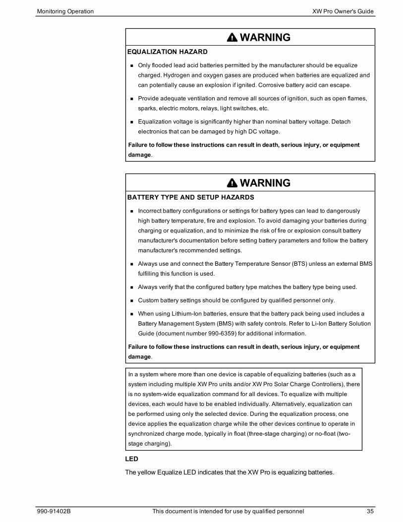
WARNINGEQUALIZATION HAZARD
n Only flooded lead acid batteries permitted by the manufacturer should be equalizecharged. Hydrogen and oxygen gases are produced when batteries are equalized andcan potentially cause an explosion if ignited. Corrosive battery acid can escape.
n Provide adequate ventilation and remove all sources of ignition, such as open flames,sparks, electric motors, relays, light switches, etc.
n Equalization voltage is significantly higher than nominal battery voltage. Detachelectronics that can be damaged by high DC voltage.
Failure to follow these instructions can result in death, serious injury, or equipmentdamage.
WARNINGBATTERY TYPE AND SETUP HAZARDS
n Incorrect battery configurations or settings for battery types can lead to dangerouslyhigh battery temperature, fire and explosion. To avoid damaging your batteries duringcharging or equalization, and to minimize the risk of fire or explosion consult batterymanufacturer's documentation before setting battery parameters and follow the batterymanufacturer's recommended settings.
n Always use and connect the Battery Temperature Sensor (BTS) unless an external BMSfulfilling this function is used.
n Always verify that the configured battery type matches the battery type being used.
n Custom battery settings should be configured by qualified personnel only.
n When using Lithium-Ion batteries, ensure that the battery pack being used includes aBattery Management System (BMS) with safety controls. Refer to Li-Ion Battery SolutionGuide (document number 990-6359) for additional information.
Failure to follow these instructions can result in death, serious injury, or equipmentdamage.
In a system where more than one device is capable of equalizing batteries (such as asystem including multiple XW Pro units and/or XW Pro Solar Charge Controllers), thereis no system-wide equalization command for all devices. To equalize with multipledevices, each would have to be enabled individually. Alternatively, equalization canbe performed using only the selected device. During the equalization process, onedevice applies the equalization charge while the other devices continue to operate insynchronized charge mode, typically in float (three-stage charging) or no-float (two-stage charging).
LED
The yellow Equalize LED indicates that the XW Pro is equalizing batteries.
Monitoring Operation XW Pro Owner's Guide
990-91402B This document is intended for use by qualified personnel 35
Symbol LED On LED Flashing
The XW Pro hasbegun equalizing thebatteries.
Equalization has been requested but has notbegun. The XW Pro must complete a chargecycle before applying the equalization charge.
Using Startup/Shutdown/Standby ModesStartup/Shutdown control
When the XW Pro is operating, pressing and holding the STARTUP/SHUTDOWN button (seeFigure 10 on page 32) for five seconds shuts down the unit. To return the unit to itsoperating state, press the STARTUP/SHUTDOWN button again.
While the XW Pro is turning off, the other inverter information panel buttons stop working.The shutdown process cannot be cancelled. The XW Pro can only be restarted once thedisplay is blank.
Standby mode
In Standby mode, the XW Pro stops charging and inverting. Also in Standby mode, theXW Pro disconnects its internal transfer switches which stops AC to pass through to theAC output. However, the unit remains powered and present on the Xanbus network.Lastly, in Standby mode, XW Pro basic and advanced settings can be changed and putinto effect.
To put the XW Pro into Standby mode, press and hold the STARTUP/SHUTDOWN buttonand the Equalize button simultaneously for about five seconds. The display shows Stb.To return the XW Pro to operatingmode, press the STARTUP/SHUTDOWN buttonmomentarily.
Pressing the STARTUP/SHUTDOWN buttonmomentarily while the XW Pro is operatingclears active faults and warnings.
Single-unit installations
In a single-unit installation, when the XW Pro is shut down using theSTARTUP/SHUTDOWN button, Xanbus network power is off. When Xanbus network poweris off, network-connected accessories such as the Automatic Generator Start (ConextAGS) and Conext Gateway could lose power and stop operating. Conext MPPT solarcharge controllers continue to operate if Xanbus network power is removed, but they donot continue to communicate with each other.
If the STARTUP/SHUTDOWN button is pressed and held on a XW Pro and a Conext AGS isinstalled in the system, the unit stops inverting or charging immediately and shuts downcompletely in 120 seconds. During this time, the display shows OFF. This interval allowsthe Conext AGS to stop the generator after a cool down period. During the 120 secondshutdown time, all network communication is blocked and the unit sends a shutdowncommand to all other devices in the system. As well, the inverter information panelbuttons stop working. The shutdown process cannot be canceled. The XW Pro can onlybe restarted again once the display is blank.
XW Pro Owner's Guide Monitoring Operation
36 This document is intended for use by qualified personnel 990-91402B

Multiple-unit installations
If the STARTUP/SHUTDOWN power button is pressed and held on amaster XW Pro and aConext AGS is installed in the system, the unit stops inverting or charging immediatelyand turns off completely in 120 seconds. During this time, the display shows OFF. Thisinterval allows the Conext AGS to stop the generator after a cool down period. During the120 second shutdown time, themaster unit stops network communication and the slaveunits issue an external sync fault (F69) or a system configuration fault (F66). As well, theinverter information panel buttons stop working. The shutdown process cannot becancelled. The XW Pro can only be restarted once the display is blank.
In amultiple-unit installation, when a slave XW Pro is shut down, other XW Pro unitscontinue to supply Xanbus network power and the Conext AGS and Conext Gatewaycontinue to operate.
Monitoring Operation XW Pro Owner's Guide
990-91402B This document is intended for use by qualified personnel 37

Monitoring Battery LevelWhen the XW Pro is inverting, the row of five LEDs indicates the approximate availableSOC (State of Charge) of the batteries connected to the system. This capacity reading isbased on battery voltage.
The battery LEDs can retrieve information from various sources depending on thedevices installed in the system. SOC information is reported from one of the followingdevices, listed in order of priority:
1. Conext Battery Monitor (If installed)
2. Conext MPPT solar charge controller (When operating)
3. XW Pro
When the XW Pro is reporting, there are five battery states from empty to full. When theavailable battery state is empty, no LEDs are lit. The battery is considered empty whenits depth of discharge exceeds approximately 50 per cent. When the battery capacity islow, the two leftmost LEDs are lit. When the battery is at medium capacity, the fourleftmost LEDs are lit. When the battery capacity is full, all five LEDs are lit. When theConext Battery Monitor or Conext MPPT solar charge controller devices are reporting,the true SOC will be indicated on the battery level LEDs and all LEDs will be utilized.
NOTE: The battery LEDs are not a precise indicator of battery level. They are to beconsidered a general guideline rather than an exact measurement. For greatestaccuracy, install the Conext Battery Monitor (Part # 865-1080-01) or refer to theexternal BMS readings, if installed.
Figure 11 Battery Level LEDs
XW Pro Owner's Guide Monitoring Operation
38 This document is intended for use by qualified personnel 990-91402B
Reading the Display ScreenThe numeric display screen shows the following information about the operational stateof the XW Pro:
n Output power in kilowatts (when the (kW) LED is lit).
n Battery charger current in Amps (when the (A) charging LED is lit).
n Stb when the XW Pro is in Standby mode.
n Sch when the XW Pro is in Searchmode.
n OFF when the STARTUP/SHUTDOWN button is pressed and held for five seconds. OFFis displayed briefly before the unit turns off.
n “---” appears when the XW Pro is in transition betweenmodes, when inverterselection is disabled via the Conext Gateway, or operating in AC passthroughmode.
n En appears momentarily when the XW Pro is enabled.
n dIS appears momentarily when the XW Pro is disabled.
n 5minute countdown timer valuemay appear if there is no other more significantinformation to display after grid interruption during energy export operation.
Monitoring Operation with the Conext GatewayThe Conext Gateway provides remote configuration andmonitoring capability for the XWPro and all other Xanbus-enabled devices in the network via its browser-based webapplication. It is the primary and recommended way tomonitor operations of allnetworked devices.
Accessing the Device in the Web ApplicationRefer to Logging in to the Conext Gateway Web Application in the Conext GatewayOwner’s Guide to gain access to the web application. If connectivity between systemcomponents are working, networked XW Pro units can be accessed by clicking thedevice icon in theDashboard screen, or its instance under theDevicesmenu.
Status PageThe XW Pro Status page displays real-time operational data specific to the selected XWPro instance. In Tables 2 and 3 are all possible states that can be shown for InverterStatus and Charger Status.
Monitoring Operation XW Pro Owner's Guide
990-91402B This document is intended for use by qualified personnel 39
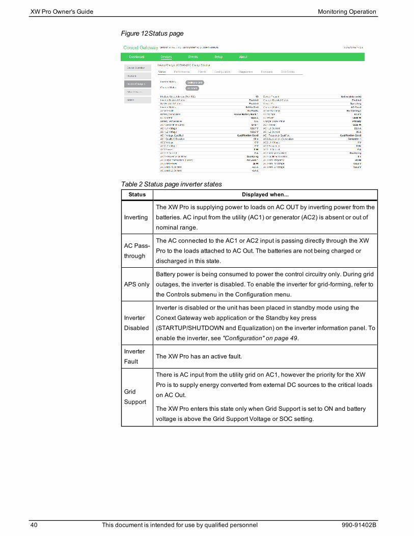
Figure 12Status page
Status Displayed when...
InvertingThe XW Pro is supplying power to loads on AC OUT by inverting power from thebatteries. AC input from the utility (AC1) or generator (AC2) is absent or out ofnominal range.
AC Pass-through
The AC connected to the AC1 or AC2 input is passing directly through the XWPro to the loads attached to AC Out. The batteries are not being charged ordischarged in this state.
APS onlyBattery power is being consumed to power the control circuitry only. During gridoutages, the inverter is disabled. To enable the inverter for grid-forming, refer tothe Controls submenu in the Configuration menu.
InverterDisabled
Inverter is disabled or the unit has been placed in standby mode using theConext Gateway web application or the Standby key press(STARTUP/SHUTDOWN and Equalization) on the inverter information panel. Toenable the inverter, see "Configuration" on page 49.
InverterFault
The XW Pro has an active fault.
GridSupport
There is AC input from the utility grid on AC1, however the priority for the XWPro is to supply energy converted from external DC sources to the critical loadson AC Out.
The XW Pro enters this state only when Grid Support is set to ON and batteryvoltage is above the Grid Support Voltage or SOC setting.
Table 2 Status page inverter states
XW Pro Owner's Guide Monitoring Operation
40 This document is intended for use by qualified personnel 990-91402B

Status Displayed when...
GenSupport
There is AC input from the generator on AC2, and the XW Pro is supporting thegenerator by supplying additional power to the loads attached to AC Out.
The XW Pro supports the generator (or other power source connected to thegenerator [default AC2] input) when the AC load current drawn from thegenerator exceeds the Generator Support Amps setting for 1 to 2 seconds.
The XW Pro uses stored battery energy to load share with the generator until thetotal AC load current (generator plus XW Pro output) drops by 2 amps plus 10per cent of the Generator Support Amps setting for 0.5 seconds.
For example, if Generator Support Amps is set to 10 amps, the XW Pro starts tosupport when the load exceeds 10 amps for 2 seconds and stops when it dropsmore than 3 amps below the Generator Support Amps setting, or 7 amps (2amps plus 10 per cent of 10 amps = 3 amps).
The system can enter this state if the battery voltage is above Low Batt Cut Out+2V and generator support is enabled. Refer to "Configuration" on page 49.
Selling toGrid
The XW Pro is grid-tied and is exporting energy to the utility grid on AC1. BothGrid Support and Sell must be enabled in order to sell power back to the utility.Refer to "Configuration" on page 49. All configurations must comply with localand national electrical codes.
LoadShaving
The XW Pro supports the utility grid when there is AC input on AC1 and thecurrent required to power the loads rises above the Load Shave Amps settingbetween the Load Shave Start and Load Shave Stop times set on the GridSupport menu. However, AC charging including force charging is disabledduring these times. AC charging is enabled when battery voltage falls below[LBCO + 1V], or when battery SOC falls below the SOC LBCO. For anillustration, refer to Figure 17 on page 75 .
When load shaving, the XW Pro uses stored battery energy to reduce the peakload on the AC1 input by providing the difference between the actual loadcurrent and the Load Shave Amps setting. The XW Pro enters this state onlywhen Grid Support is enabled, the load shave time window is valid and the loaddraw exceeds the Load Shave Amps setting. The battery voltage must also bebetween Recharge Volts +0.5 V and the Grid Support Voltage setting orRecharge SOC and Grid Support SOC settings respectively if SOC control isenabled. Refer to "Configuration" on page 49.
ACCoupling
If AC Coupling is enabled, the XW Pro is modulating the incoming power fromany AC-coupled PV inverters as needed via frequency-shifting.
Monitoring Operation XW Pro Owner's Guide
990-91402B This document is intended for use by qualified personnel 41
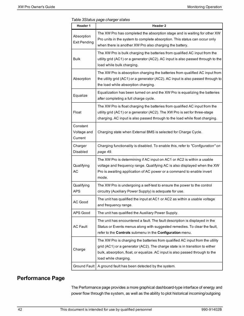
Header 1 Header 2
AbsorptionExit Pending
The XW Pro has completed the absorption stage and is waiting for other XWPro units in the system to complete absorption. This status can occur onlywhen there is another XW Pro also charging the battery.
BulkThe XW Pro is bulk charging the batteries from qualified AC input from theutility grid (AC1) or a generator (AC2). AC input is also passed through to theload while bulk charging.
AbsorptionThe XW Pro is absorption charging the batteries from qualified AC input fromthe utility grid (AC1) or a generator (AC2). AC input is also passed through tothe load while absorption charging.
EqualizeEqualization has been turned on and the XW Pro is equalizing the batteriesafter completing a full charge cycle.
FloatThe XW Pro is float charging the batteries from qualified AC input from theutility grid (AC1) or a generator (AC2). The XW Pro is set for three-stagecharging. AC input is also passed through to the load while float charging.
ConstantVoltage andCurrent
Charging state when External BMS is selected for Charge Cycle.
ChargerDisabled
Charging functionality is disabled. To enable this, refer to "Configuration" onpage 49.
QualifyingAC
The XW Pro is determining if AC input on AC1 or AC2 is within a usablevoltage and frequency range. Qualifying AC is also displayed when the XWPro is awaiting application of AC power or a command to enable invertmode.
QualifyingAPS
The XW Pro is undergoing a self-test to ensure the power to the controlcircuitry (Auxiliary Power Supply) is adequate for use.
AC GoodThe unit has qualified the input at AC1 or AC2 as within a usable voltageand frequency range.
APS Good The unit has qualified the Auxiliary Power Supply.
AC FaultThe unit has encountered a fault. The fault description is displayed in theStatus or Events menus along with suggested remedies. To clear the fault,refer to the Controls submenu in the Configurationmenu.
Charge
The XW Pro is charging the batteries from qualified AC input from the utilitygrid (AC1) or a generator (AC2). The charge state is in transition to eitherbulk, absorption, float, or equalize. AC input is also passed through to theload while charging.
Ground Fault A ground fault has been detected by the system.
Table 3Status page charger states
Performance PageThe Performance page provides amore graphical dashboard-type interface of energy andpower flow through the system, as well as the ability to plot historical incoming/outgoing
XW Pro Owner's Guide Monitoring Operation
42 This document is intended for use by qualified personnel 990-91402B
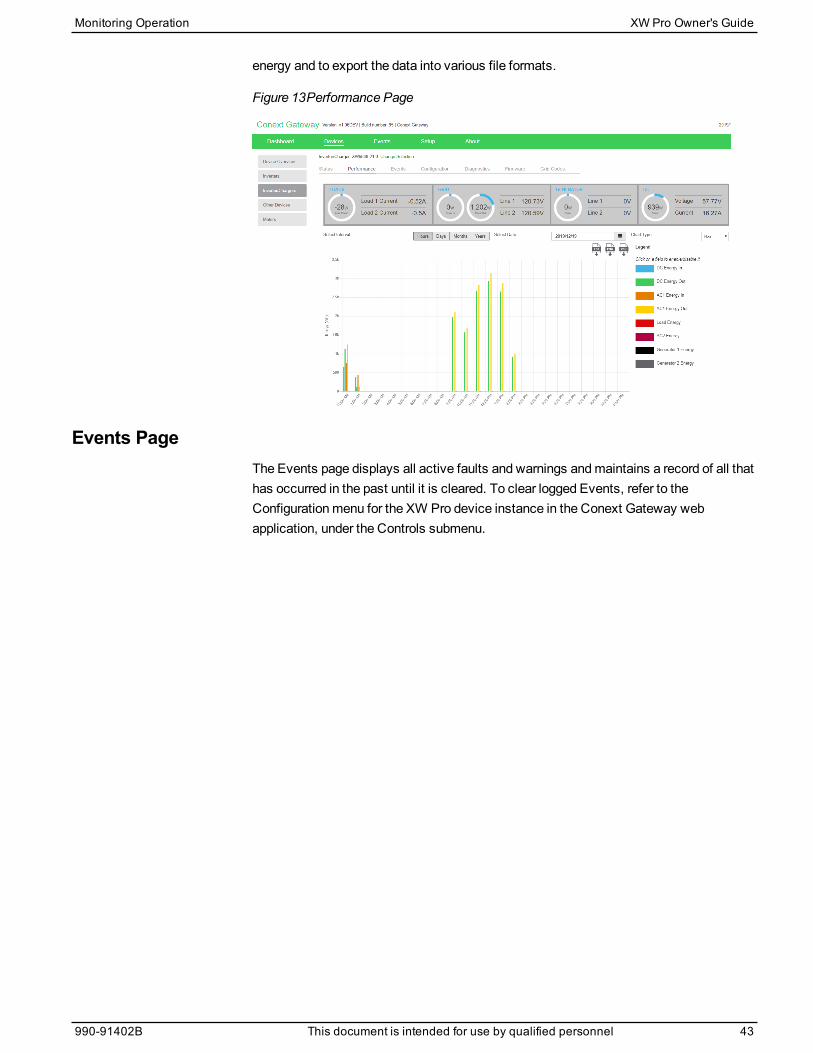
energy and to export the data into various file formats.
Figure 13Performance Page
Events PageThe Events page displays all active faults and warnings andmaintains a record of all thathas occurred in the past until it is cleared. To clear logged Events, refer to theConfigurationmenu for the XW Pro device instance in the Conext Gateway webapplication, under the Controls submenu.
Monitoring Operation XW Pro Owner's Guide
990-91402B This document is intended for use by qualified personnel 43

External Monitoring Control3
Overview 46SunSpec Modbus 46Power Limiting 46Communications Loss 46
IEEE2030.5 47Demand Response Mode 0 (DRM0) 47
What's in This Chapter?

OverviewThe XW Pro digital communications interface with the Conext Gatewaysupportscommands from external equipment to control power output and operational modes,which allows support for industry-accepted communication standards SunSpec Modbusand IEEE2030.5.
Figure 14 SunSpec Configuration
Conext XW Pro
Conext Gateway
Utility
External Controller
Controller Heartbeat Control Mode Slow P Commands
Control Mode Slow P Commands
Gateway Heartbeat Controller Heartbeat Control Mode Slow P Commands
SunSpec ModbusThe XW Pro supports the following datamodels from the SunSpec Modbus specificationvia the Conext Gateway.
SunSpec Model Name Description
Model 1 Equipment Identification
Model 102 Split-Phase Inverter Monitoring
Model 121 Basic Settings
Model 123 Immediate Controls
Model 124 Storage Controls
Model 20001 Inverter Custom Model
Power LimitingExternally-controlled power limits are applied at the AC transformer at the inverter outputprior to connecting with the AC bus. During Selling, XW Pro arbitrates between allsources of power limitation, including externally-controlled limits, by taking theminimum.If the system receives a lower power request than what is currently in effect, the XW Prowill control power flow to the new limit.
Similarly, during Peak Load Shaving, the lower of Load Shave Amps and the externally-controlled limit minus the load power is taken.
Communications LossCommunications with the SunSpec Controller is continuously monitored. When acommunications loss with either the Conext Gateway or the SunSpec Controller isdetected, the XW Pro supports the following configurable responses via a datapoint inModel 20001. This setting cannot be set in theConext Gateway web application.
XW Pro Owner's Guide External Monitoring Control
46 This document is intended for use by qualified personnel 990-91402B
Fallback Action Datapoint Value Description
Heartbeat Disabled 0 (default) Commands revert to default untilcommunication is re-established. Awarning will not appear.
Do Nothing 1 Continue with the last received setof control parameters. A warningwill appear.
Autonomous Operation 2 Commands revert to default untilcommunication is re-established. Awarning will appear.
AC Passthrough 3 3 XW Pro transitions to ACPassthrough mode. A warning willappear.
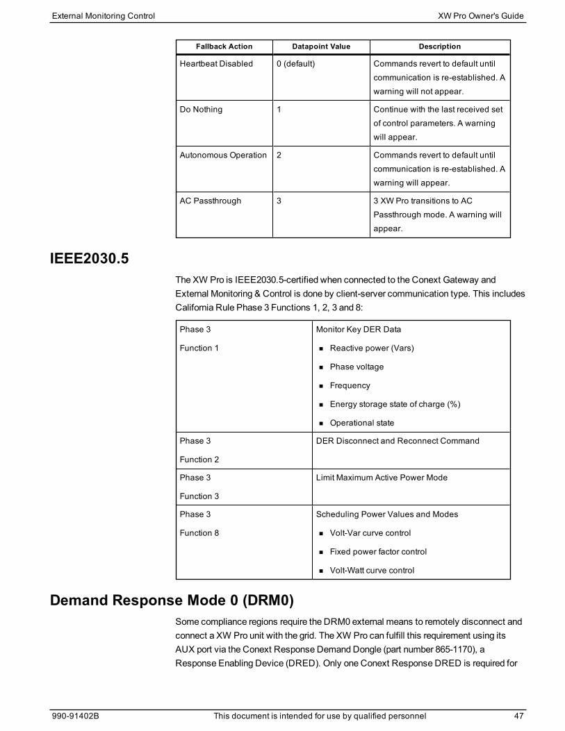
IEEE2030.5The XW Pro is IEEE2030.5-certified when connected to the Conext Gateway andExternal Monitoring & Control is done by client-server communication type. This includesCalifornia Rule Phase 3 Functions 1, 2, 3 and 8:
Phase 3
Function 1
Monitor Key DER Data
n Reactive power (Vars)
n Phase voltage
n Frequency
n Energy storage state of charge (%)
n Operational state
Phase 3
Function 2
DER Disconnect and Reconnect Command
Phase 3
Function 3
Limit Maximum Active Power Mode
Phase 3
Function 8
Scheduling Power Values and Modes
n Volt-Var curve control
n Fixed power factor control
n Volt-Watt curve control
Demand Response Mode 0 (DRM0)Some compliance regions require the DRM0 external means to remotely disconnect andconnect a XW Pro unit with the grid. The XW Pro can fulfill this requirement using itsAUX port via the Conext Response Demand Dongle (part number 865-1170), aResponse Enabling Device (DRED). Only one Conext Response DRED is required for
External Monitoring Control XW Pro Owner's Guide
990-91402B This document is intended for use by qualified personnel 47

each system and it is connected to theMaster unit in amulti-unit system. In a three-phase system, the connection is made to the Phase 1Master.
For more information about this product and a setup guide, refer to the Conext ResponseQuick SetupGuide (document number 975-0771-01-01). For information on configuringthe XW Pro with a Conext Response, refer to "Configuration for DRM0" on page 87
XW Pro Owner's Guide External Monitoring Control
48 This document is intended for use by qualified personnel 990-91402B
Configuration4
Configuration with the Conext Gateway Web Application 50Accessing theWeb Application 50Setting the Device Name 51Setting the Device Number 51Setting the Time and Date 52
XW Pro Configuration Page 52Controls Settings 52Inverter Settings 53Charger Settings 57AC Settings 69Grid Support Settings 73Generator Support Settings 77Auxiliary Output Settings 79Multi-Unit ConfigurationMenu 82Associations Settings 84Advanced Features 85Advanced Device Settings 87Battery Management System Settings 88Device Instance Settings 90Modbus Settings 90
Prioritizing and Managing Energy Sources with Advanced Features 92Grid Support 92Charger Block 95Peak Load Shaving (PLS) 95
Managing Firmware 98Managing Compliance Regions 99Grid Support Utility Interactive Functions 100AS/NZS 4777.2-2015 Australia 102
Resetting the XW Pro to Default Settings 111
What's in This Chapter?

Configuration with the Conext Gateway Web ApplicationThe XW Pro is configured primarily using the Conext Gateway web application interface.The Conext Gateway provides access to settings relating to AC input and output, batterycharging, compliance regions, and grid-tie operation. Refer to theConext GatewayOwner’s Guidemore details.
Accessing the Web ApplicationRefer to "Logging in to the Conext Gateway Web Application" in theConext GatewayOwner’s Guide to gain access to the web application. If connectivity between systemcomponents are working, a XW Pro can be accessed by clicking the device figure in theDashboard screen, or its instance under the Devices menu. Device configuration isavailable only to the Administrator access level.
NOTICEEQUIPMENT DAMAGE
Ensure you put the XW Pro in Standby mode prior to changing basic or advanced settings.Return to Operating mode for the settings to take effect.
Any configuration (change in settings) made when theXW Pro is in Operating mode will notbe saved unless theXW Pro is put in Standby mode and then back to Operating mode.
Failure to follow these instructions can result in equipment damage.
XW Pro Owner's Guide Configuration
50 This document is intended for use by qualified personnel 990-91402B
Setting the Device NameThe Dev Name setting allows you to customize the name of the XW Pro as it isdisplayed on other screens andmenus.
The characters available are:
n A to Z
n a to z
n 0 to 9
n space
NOTE: Increasing the number of characters in a device namemay cause other text onthe same line to run off the edge of the screen. Device names should be limited to 10characters or less.
The XW Pro device name can be set at the device’s Configuration page in the ConextGateway web application under the Device Instancemenu.
NOTE: It is also possible to change the device name using the Conext ConfigurationTool. Please refer to the Owner’s Guides for the Conext Configuration Tool for furtherinformation.
Setting the Device NumberWhen several devices of the same type are installed in the Xanbus network, setting thedevice number is required to give a Xanbus-enabled device a unique identity. When eachidentical device has a unique number, the Conext Gateway web application can correctlyidentify and display status information for each device. A device number consists of twodigits ranging from 0 (default) to 247.
If only one of each type of device is installed in the networked power system, a devicenumber is not needed. However, setting the device number to a value other than 0 isrecommended in case you need to use the Restore Defaults command. This commandresets the device number to 0. After performing the command, checking that the devicenumber has returned to 0 indicates that the commandwas successfully completed. TheDevice Number can be set at the device’s Configuration page in the Conext Gatewayweb application under Device Instance.
Configuration XW Pro Owner's Guide
990-91402B This document is intended for use by qualified personnel 51
Setting the Time and DateXW Pro advanced features such as peak load shaving, charger block, and time-stampedevents (faults, warnings, and logged historical data) require that the system be set to thecorrect time. The Conext Gateway has an internal clock that controls the time for theXanbus-enabled devices in the system. You can set the time, time format, and date onthe Clock menu. The Time Setupmenu is accessible under Configuration in the ConextGateway Setup Screen where the time zone, time, and date are adjustable.
For more information, see “Changing the Time” in theConext Gateway Owner’s Guide.
XW Pro Configuration PageThe XW Pro device's configurable operating parameters can be found on theConfiguration page within the Conext Gateway web application in the device instance’sownmenus. This document will also cover the additional parameters available in theAdvanced view.
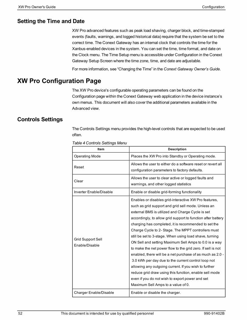
Controls SettingsThe Controls Settings menu provides the high-level controls that are expected to be usedoften.
Item Description
Operating Mode Places the XW Pro into Standby or Operating mode.
ResetAllows the user to either do a software reset or revert allconfiguration parameters to factory defaults.
ClearAllows the user to clear active or logged faults andwarnings, and other logged statistics
Inverter Enable/Disable Enable or disable grid-forming functionality
Grid Support SellEnable/Disable
Enables or disables grid-interactive XW Pro features,such as grid support and grid sell mode. Unless anexternal BMS is utilized and Charge Cycle is setaccordingly, to allow grid support to function after batterycharging has completed, it is recommended to set theCharge Cycle to 2- Stage. The MPPT controllers muststill be set to 3-stage. When using load shave, turningON Sell and setting Maximum Sell Amps to 0.0 is a wayto make the net power flow to the grid zero. If sell is notenabled, there will be a net purchase of as much as 2.0 -3.0 kWh per day due to the current control loop notallowing any outgoing current. If you wish to furtherreduce grid draw using this function, enable sell modeeven if you do not wish to export power and setMaximum Sell Amps to a value of 0.
Charger Enable/Disable Enable or disable the charger.
Table 4 Controls Settings Menu
XW Pro Owner's Guide Configuration
52 This document is intended for use by qualified personnel 990-91402B
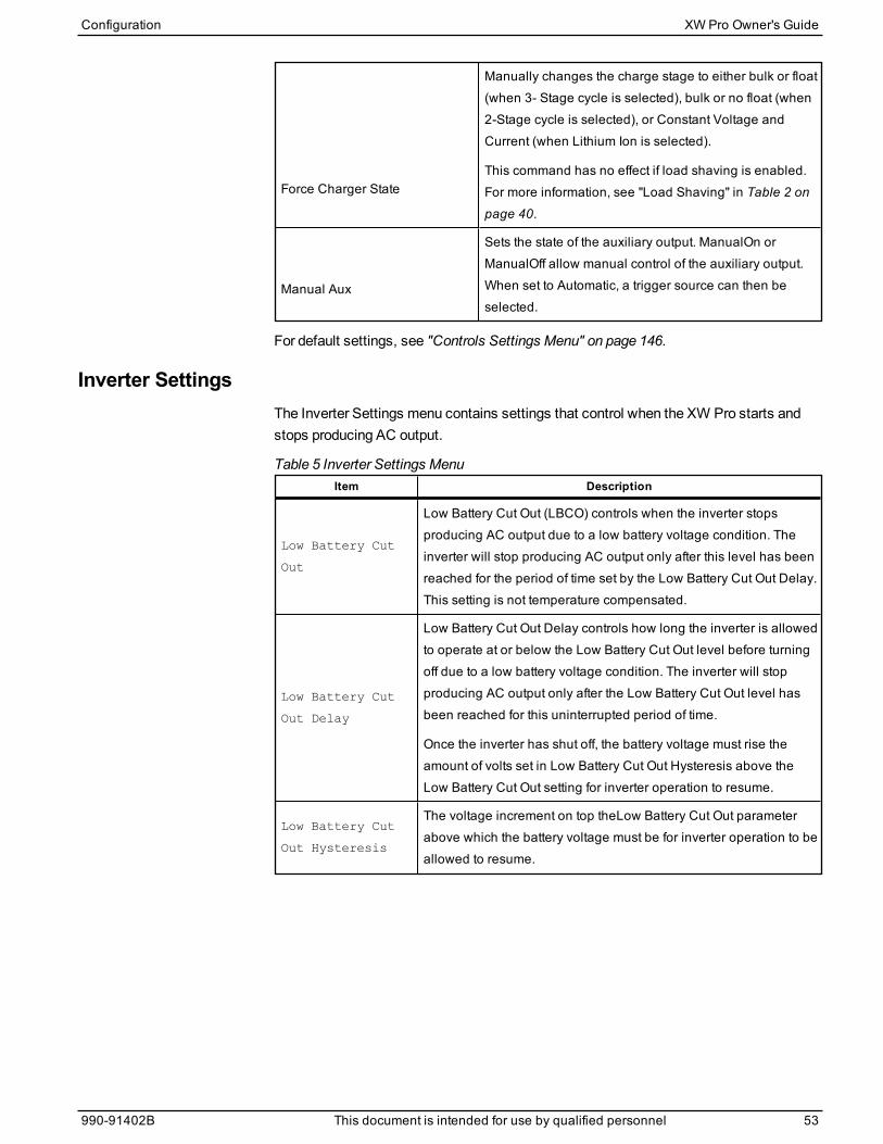
Force Charger State
Manually changes the charge stage to either bulk or float(when 3- Stage cycle is selected), bulk or no float (when2-Stage cycle is selected), or Constant Voltage andCurrent (when Lithium Ion is selected).
This command has no effect if load shaving is enabled.For more information, see "Load Shaving" in Table 2 onpage 40.
Manual Aux
Sets the state of the auxiliary output. ManualOn orManualOff allow manual control of the auxiliary output.When set to Automatic, a trigger source can then beselected.
For default settings, see "Controls Settings Menu" on page 146.
Inverter SettingsThe Inverter Settings menu contains settings that control when the XW Pro starts andstops producing AC output.
Item Description
Low Battery Cut
Out
Low Battery Cut Out (LBCO) controls when the inverter stopsproducing AC output due to a low battery voltage condition. Theinverter will stop producing AC output only after this level has beenreached for the period of time set by the Low Battery Cut Out Delay.This setting is not temperature compensated.
Low Battery Cut
Out Delay
Low Battery Cut Out Delay controls how long the inverter is allowedto operate at or below the Low Battery Cut Out level before turningoff due to a low battery voltage condition. The inverter will stopproducing AC output only after the Low Battery Cut Out level hasbeen reached for this uninterrupted period of time.
Once the inverter has shut off, the battery voltage must rise theamount of volts set in Low Battery Cut Out Hysteresis above theLow Battery Cut Out setting for inverter operation to resume.
Low Battery Cut
Out Hysteresis
The voltage increment on top theLow Battery Cut Out parameterabove which the battery voltage must be for inverter operation to beallowed to resume.
Table 5 Inverter Settings Menu
Configuration XW Pro Owner's Guide
990-91402B This document is intended for use by qualified personnel 53
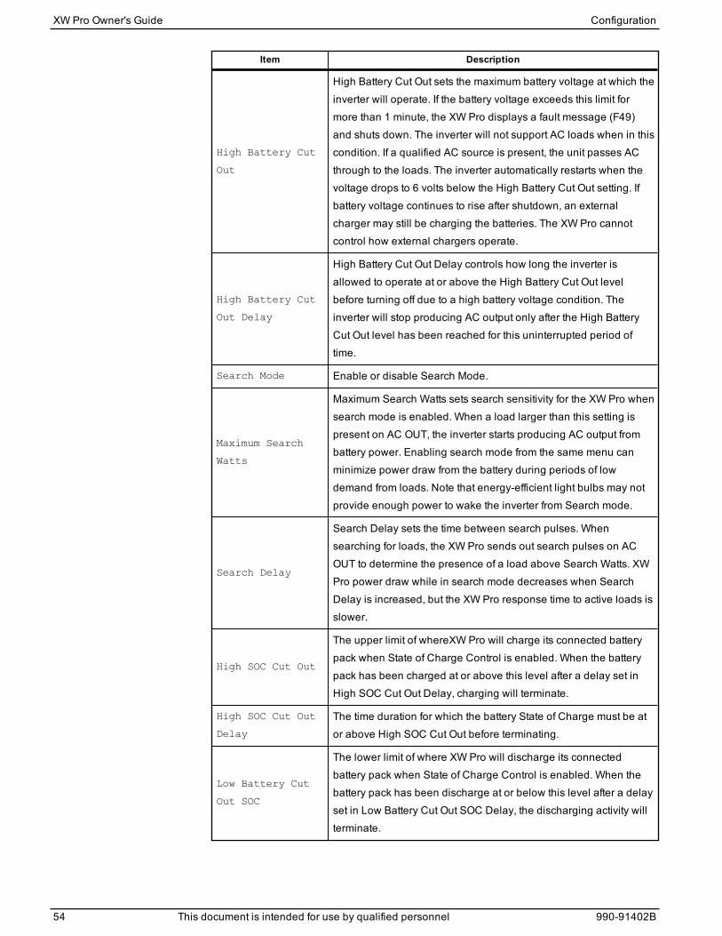
Item Description
High Battery Cut
Out
High Battery Cut Out sets the maximum battery voltage at which theinverter will operate. If the battery voltage exceeds this limit formore than 1 minute, the XW Pro displays a fault message (F49)and shuts down. The inverter will not support AC loads when in thiscondition. If a qualified AC source is present, the unit passes ACthrough to the loads. The inverter automatically restarts when thevoltage drops to 6 volts below the High Battery Cut Out setting. Ifbattery voltage continues to rise after shutdown, an externalcharger may still be charging the batteries. The XW Pro cannotcontrol how external chargers operate.
High Battery Cut
Out Delay
High Battery Cut Out Delay controls how long the inverter isallowed to operate at or above the High Battery Cut Out levelbefore turning off due to a high battery voltage condition. Theinverter will stop producing AC output only after the High BatteryCut Out level has been reached for this uninterrupted period oftime.
Search Mode Enable or disable Search Mode.
Maximum Search
Watts
Maximum Search Watts sets search sensitivity for the XW Pro whensearch mode is enabled. When a load larger than this setting ispresent on AC OUT, the inverter starts producing AC output frombattery power. Enabling search mode from the same menu canminimize power draw from the battery during periods of lowdemand from loads. Note that energy-efficient light bulbs may notprovide enough power to wake the inverter from Search mode.
Search Delay
Search Delay sets the time between search pulses. Whensearching for loads, the XW Pro sends out search pulses on ACOUT to determine the presence of a load above Search Watts. XWPro power draw while in search mode decreases when SearchDelay is increased, but the XW Pro response time to active loads isslower.
High SOC Cut Out
The upper limit of whereXW Pro will charge its connected batterypack when State of Charge Control is enabled. When the batterypack has been charged at or above this level after a delay set inHigh SOC Cut Out Delay, charging will terminate.
High SOC Cut Out
Delay
The time duration for which the battery State of Charge must be ator above High SOC Cut Out before terminating.
Low Battery Cut
Out SOC
The lower limit of where XW Pro will discharge its connectedbattery pack when State of Charge Control is enabled. When thebattery pack has been discharge at or below this level after a delayset in Low Battery Cut Out SOC Delay, the discharging activity willterminate.
XW Pro Owner's Guide Configuration
54 This document is intended for use by qualified personnel 990-91402B

Item Description
Low Battery Cut
Out SOC Delay
The time duration for which the battery State of Charge must be ator below Low Battery Cut Out SOC before terminating thedischarge.
Action on
Communication
Loss
Configures the action taken during a general communications losswith the Conext Gateway.
For default settings, see "Inverter Settings Menu" on page 146.
Using the Low Battery Cut Out and LBCO Delay Settings
WARNINGADVANCED CONFIGURATION HAZARD
n Advanced menu settings should be used by qualified personnel only.
n Three phase operation should be configured by qualified personnel only.
n Consult with the local utility before enabling XW Pro sell mode or grid support functions.
n Do not change these settings unless you are under the supervision and direction ofqualified personnel.
n Connect the Conext Gateway and the network router connected to the Conext Gatewayto an assured power source during configuration.
Failure to follow these instructions can result in death, serious injury, or equipmentdamage.
The Low Battery Cut Out setting is the lowest battery voltage or SOC level acceptablefor use by the inverter. When the batteries discharge to the Low Battery Cut Out setting,and are held at or below this level for the LBCODelay time, the inverter output shutsdown and connects any available AC source (AC1 or AC2) to the charger to bring thebattery level back above the Low Battery Cut Out setting. After shutdown, the inverterdoes not support loads on AC OUT, and AC loads must be powered by either a generator(AC2) or grid power (AC1). If the battery voltage or SOC stays below the LBCO thresholdfor more than 24 hours, the XW Pro shuts down.
If using the Conext Automatic Generator Start system, it is recommended to set the AGSvoltage or low SOC trigger setting higher than the XW Pro Low Battery Cut Out voltage orSOC level.
Although not recommended, if using the Conext Automatic Generator Start system withthe start trigger set to the same voltage as the LBCO voltage, do not set the LBCODelayfor less than the amount of time it takes the generator to start and connect.
Otherwise – in both of the scenarios above – inverter output turns off before the generatorautomatically starts, causing the battery voltage to recover slightly. This may then stopthe AGS from starting the generator or result in the XW Pro cycling on and off multipletimes before the generator automatically starts.
Configuration XW Pro Owner's Guide
990-91402B This document is intended for use by qualified personnel 55
Using Search Mode
Why use Search mode?Searchmode allows the inverter to selectively power only items that draw more than acertain amount of power, which can result in energy savings. The XW Pro has a no-loadpower draw of about 28 watts. Enabling searchmode reduces this power draw to lessthan 8 watts. Search mode operates differently in single-unit andmulti-unit installations.
Single unitsWhen a single XW Pro has searchmode enabled, the inverter sends electrical searchpulses through its AC output. These search pulses look for connected AC loads. Thedelay between search pulses is set using the Search Delay setting. After a load largerthan the SearchWatts setting is detected, the inverter starts producing AC output.
Multiple unitsIt is not recommended to use searchmode for XW Pro inverters in amulti-unitconfiguration.
When to set up Search modeThe searchmode feature is only valuable if the inverter can spend a fair amount of time“sleeping” each day. Therefore, if searchmode is to be used it must be adjusted properly.The initial adjustment should bemade so that the XW Pro comes on only when needed.
Certain types of loads can cause searchmode to work improperly. These types of loadsare described in "Problem Loads" on page 115. If these kinds of loads are in the system,follow the suggestions given to resolve the problem.
If the problem loads cannot be resolved, there are two workaround solutions:
Disable searchmode from themain XW Pro Setupmenu, causing the inverter to remainat full output voltage.
Use a search friendly companion load whose only purpose is to be switched on to wakeup the inverter to power the load that is unable to bring the inverter out of searchmode.
NOTE: Searchmode, by function, cannot work with clocks and timers or devices thatneed power 24 hours a day. Examples of devices with timers include video recorders,coffeemakers with brew timers, refrigerators, and freezers with defrost timers.Examples of devices that need power 24 hours a day include telephone answeringmachines, alarm systems, motion detection lights, and some thermostats.
When the inverter is searching the output for loads, lights that have a wattage lower thanthis settingmay flashmomentarily.
XW Pro Owner's Guide Configuration
56 This document is intended for use by qualified personnel 990-91402B
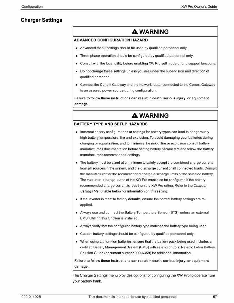
Charger Settings
WARNINGADVANCED CONFIGURATION HAZARD
n Advanced menu settings should be used by qualified personnel only.
n Three phase operation should be configured by qualified personnel only.
n Consult with the local utility before enabling XW Pro sell mode or grid support functions.
n Do not change these settings unless you are under the supervision and direction ofqualified personnel.
n Connect the Conext Gateway and the network router connected to the Conext Gatewayto an assured power source during configuration.
Failure to follow these instructions can result in death, serious injury, or equipmentdamage.
WARNINGBATTERY TYPE AND SETUP HAZARDS
n Incorrect battery configurations or settings for battery types can lead to dangerouslyhigh battery temperature, fire and explosion. To avoid damaging your batteries duringcharging or equalization, and to minimize the risk of fire or explosion consult batterymanufacturer's documentation before setting battery parameters and follow the batterymanufacturer's recommended settings.
n The battery must be sized at a minimum to safely accept the combined charge currentfrom all sources in the system, and the discharge current of all connected loads. Consultthe manufacturer for the recommended charge/discharge limits of the selected battery.The Maximum Charge Rate of the XW Pro must also be configured if the batteryrecommended charge current is less than the XW Pro rating. Refer to the ChargerSettings Menu table below for information on this setting.
n If the inverter is reset to factory defaults, ensure the correct battery settings are re-applied.
n Always use and connect the Battery Temperature Sensor (BTS), unless an externalBMS fulfilling this function is installed.
n Always verify that the configured battery type matches the battery type being used.
n Custom battery settings should be configured by qualified personnel only.
n When using Lithium-Ion batteries, ensure that the battery pack being used includes acertified Battery Management System (BMS) with safety controls. Refer to Li-Ion BatterySolution Guide (document number 990-6359) for additional information.
Failure to follow these instructions can result in death, serious injury, or equipmentdamage.
The Charger Settings menu provides options for configuring the XW Pro to operate fromyour battery bank.
Configuration XW Pro Owner's Guide
990-91402B This document is intended for use by qualified personnel 57
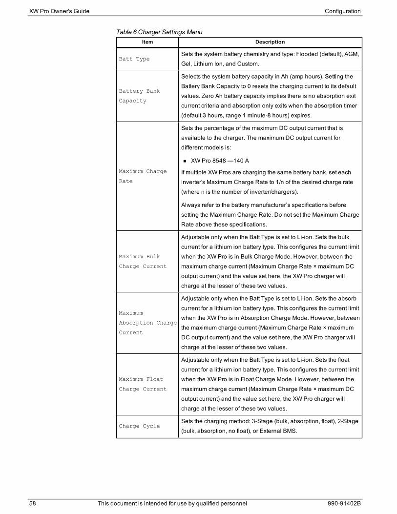
Item Description
Batt TypeSets the system battery chemistry and type: Flooded (default), AGM,Gel, Lithium Ion, and Custom.
Battery Bank
Capacity
Selects the system battery capacity in Ah (amp hours). Setting theBattery Bank Capacity to 0 resets the charging current to its defaultvalues. Zero Ah battery capacity implies there is no absorption exitcurrent criteria and absorption only exits when the absorption timer(default 3 hours, range 1 minute-8 hours) expires.
Maximum Charge
Rate
Sets the percentage of the maximum DC output current that isavailable to the charger. The maximum DC output current fordifferent models is:
n XW Pro 8548 —140 A
If multiple XW Pros are charging the same battery bank, set eachinverter's Maximum Charge Rate to 1/n of the desired charge rate(where n is the number of inverter/chargers).
Always refer to the battery manufacturer’s specifications beforesetting the Maximum Charge Rate. Do not set the Maximum ChargeRate above these specifications.
Maximum Bulk
Charge Current
Adjustable only when the Batt Type is set to Li-ion. Sets the bulkcurrent for a lithium ion battery type. This configures the current limitwhen the XW Pro is in Bulk Charge Mode. However, between themaximum charge current (Maximum Charge Rate × maximum DCoutput current) and the value set here, the XW Pro charger willcharge at the lesser of these two values.
Maximum
Absorption Charge
Current
Adjustable only when the Batt Type is set to Li-ion. Sets the absorbcurrent for a lithium ion battery type. This configures the current limitwhen the XW Pro is in Absorption Charge Mode. However, betweenthe maximum charge current (Maximum Charge Rate × maximumDC output current) and the value set here, the XW Pro charger willcharge at the lesser of these two values.
Maximum Float
Charge Current
Adjustable only when the Batt Type is set to Li-ion. Sets the floatcurrent for a lithium ion battery type. This configures the current limitwhen the XW Pro is in Float Charge Mode. However, between themaximum charge current (Maximum Charge Rate × maximum DCoutput current) and the value set here, the XW Pro charger willcharge at the lesser of these two values.
Charge CycleSets the charging method: 3-Stage (bulk, absorption, float), 2-Stage(bulk, absorption, no float), or External BMS.
Table 6 Charger Settings Menu
XW Pro Owner's Guide Configuration
58 This document is intended for use by qualified personnel 990-91402B
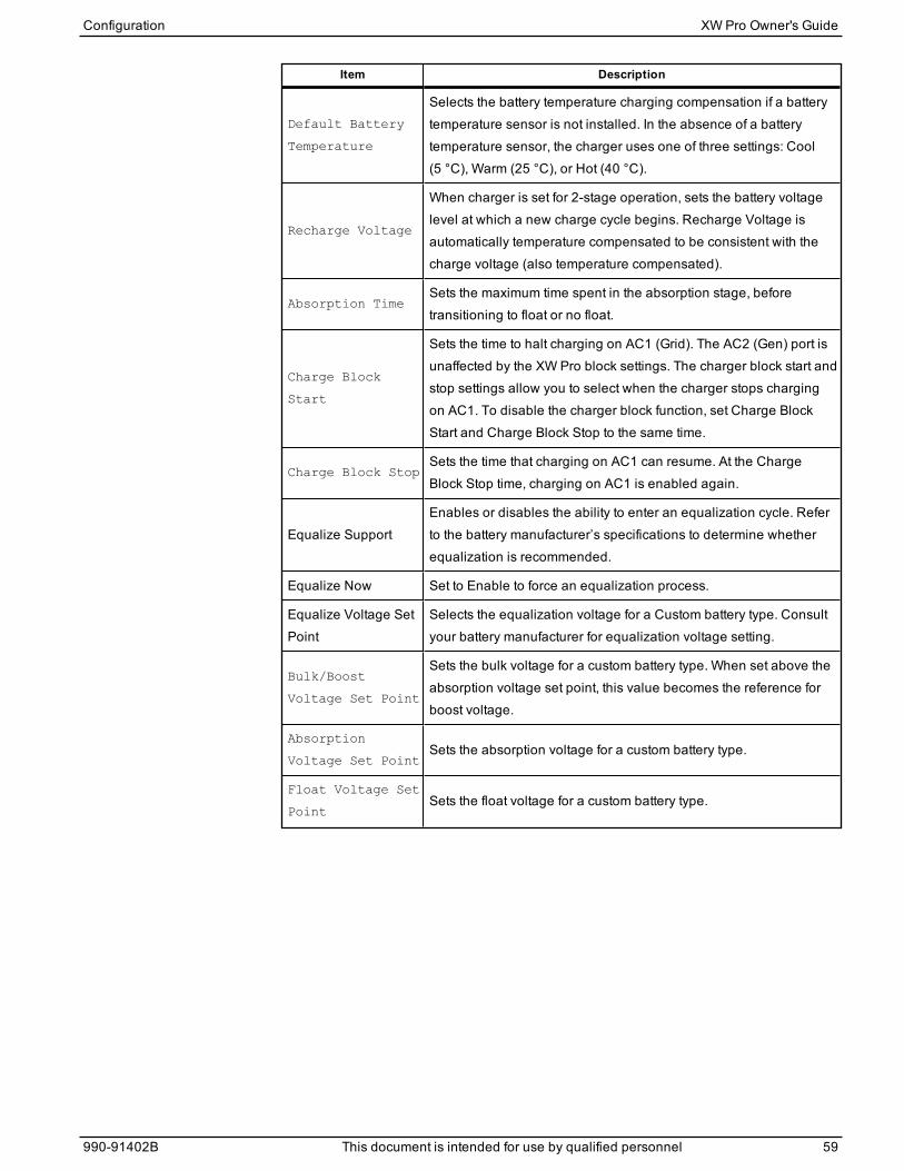
Item Description
Default Battery
Temperature
Selects the battery temperature charging compensation if a batterytemperature sensor is not installed. In the absence of a batterytemperature sensor, the charger uses one of three settings: Cool(5 °C), Warm (25 °C), or Hot (40 °C).
Recharge Voltage
When charger is set for 2-stage operation, sets the battery voltagelevel at which a new charge cycle begins. Recharge Voltage isautomatically temperature compensated to be consistent with thecharge voltage (also temperature compensated).
Absorption TimeSets the maximum time spent in the absorption stage, beforetransitioning to float or no float.
Charge Block
Start
Sets the time to halt charging on AC1 (Grid). The AC2 (Gen) port isunaffected by the XW Pro block settings. The charger block start andstop settings allow you to select when the charger stops chargingon AC1. To disable the charger block function, set Charge BlockStart and Charge Block Stop to the same time.
Charge Block StopSets the time that charging on AC1 can resume. At the ChargeBlock Stop time, charging on AC1 is enabled again.
Equalize SupportEnables or disables the ability to enter an equalization cycle. Referto the battery manufacturer’s specifications to determine whetherequalization is recommended.
Equalize Now Set to Enable to force an equalization process.
Equalize Voltage SetPoint
Selects the equalization voltage for a Custom battery type. Consultyour battery manufacturer for equalization voltage setting.
Bulk/Boost
Voltage Set Point
Sets the bulk voltage for a custom battery type. When set above theabsorption voltage set point, this value becomes the reference forboost voltage.
Absorption
Voltage Set PointSets the absorption voltage for a custom battery type.
Float Voltage Set
PointSets the float voltage for a custom battery type.
Configuration XW Pro Owner's Guide
990-91402B This document is intended for use by qualified personnel 59
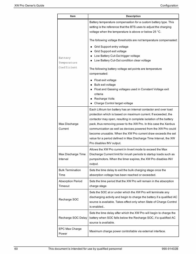
Item Description
Battery
Temperature
Coefficient
Battery temperature compensation for a custom battery type. Thissetting is the reference that the BTS uses to adjust the chargingvoltage when the temperature is above or below 25 °C.
The following voltage thresholds are not temperature compensated:
n Grid Support entry voltagen Grid Support exit voltagen Low Battery Cut-Out trigger voltagen Low Battery Cut-Out condition clear voltage
The following battery voltage set points are temperaturecompensated:
n Float exit voltagen Bulk exit voltagen Float and Gassing voltages used in Constant Voltage exit
criterian Recharge Voltsn Charge Control target voltage
Max DischargeCurrent
Each Lithium Ion battery has an internal contactor and over loadprotection which is based on maximum current. If exceeded, thecontactor may open, resulting in complete isolation of the batterypack, thus removing power to the XW Pro. In this case the Xanbuscommunication as well as devices powered from the XW Pro couldbecome unusable. When the XW Pro current draw exceeds the setvalue for a period defined in Max Discharge Time Interval, the XWPro disables INV output.
Max Discharge TimeInterval
Allows the XW Pro current in Invert mode to exceed the MaxDischarge Current limit for inrush periods to startup loads such aspumps/motors. When the timer expires, the XW Pro disables INVoutput.
Bulk TerminationTime
Sets the time delay to exit the bulk charging stage once theabsorption voltage has been reached or exceeded.
Absorption PeriodTimeout
Sets the time period that the XW Pro will remain in the absorptioncharge stage
Recharge SOC
Sets the SOC at or under which the XW Pro will terminate anydischarging activity and begin to charge the battery if a qualified ACsource is available. Takes effect only when State of Charge Controlis enabled..
Recharge SOC DelaySets the time delay after which the XW Pro will begin to charge thebattery when SOC falls below the Recharge SOC, if a qualified ACsource is available.
EPC Max ChargePower
Maximum charge power controllable via external interface.
XW Pro Owner's Guide Configuration
60 This document is intended for use by qualified personnel 990-91402B
For default settings, see "Charger Settings Menu" on page 147.
Battery Charger FunctionsWhen AC power is available, the XW Pro can operate as a battery charger. Differentbattery types and chemistries require different charging voltage levels. Not chargingbatteries at the required levels can shorten battery life or damage the batteries. The XWPro is configured at the factory to work with the battery types recommended for inverterapplications. If the default settings do not work for your specific installation, you canadjust the charge stage settings (as recommended by the battery manufacturer) bysetting the Battery Type to Custom.
NOTE: This information is provided for guidance only. Variations in battery chemistry andsite-specific environmental considerations mean that you should consult your systemdesigner or battery manufacturer for specific recommendations for appropriate batteryvoltage and current settings.
Battery MonitoringThe following table illustrates how to configure the XW Pro for the available batterymonitoringmethods.
Configuration XW Pro Owner's Guide
990-91402B This document is intended for use by qualified personnel 61
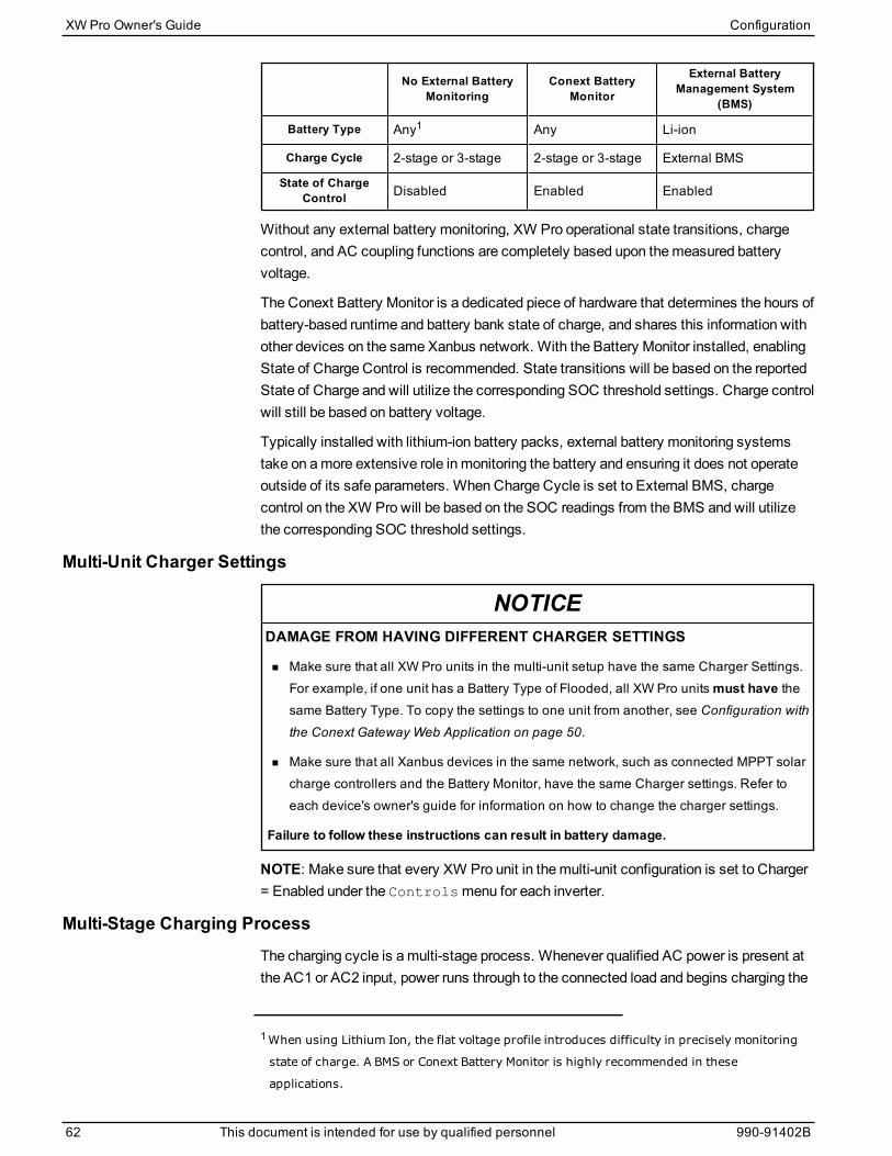
No External BatteryMonitoring
Conext BatteryMonitor
External BatteryManagement System
(BMS)
Battery Type Any1 Any Li-ion
Charge Cycle 2-stage or 3-stage 2-stage or 3-stage External BMS
State of ChargeControl Disabled Enabled Enabled
Without any external battery monitoring, XW Pro operational state transitions, chargecontrol, and AC coupling functions are completely based upon themeasured batteryvoltage.
The Conext Battery Monitor is a dedicated piece of hardware that determines the hours ofbattery-based runtime and battery bank state of charge, and shares this information withother devices on the same Xanbus network. With the Battery Monitor installed, enablingState of Charge Control is recommended. State transitions will be based on the reportedState of Charge and will utilize the corresponding SOC threshold settings. Charge controlwill still be based on battery voltage.
Typically installed with lithium-ion battery packs, external battery monitoring systemstake on amore extensive role in monitoring the battery and ensuring it does not operateoutside of its safe parameters. When Charge Cycle is set to External BMS, chargecontrol on the XW Pro will be based on the SOC readings from the BMS and will utilizethe corresponding SOC threshold settings.
Multi-Unit Charger Settings
NOTICEDAMAGE FROM HAVING DIFFERENT CHARGER SETTINGS
n Make sure that all XW Pro units in the multi-unit setup have the same Charger Settings.For example, if one unit has a Battery Type of Flooded, all XW Pro unitsmust have thesame Battery Type. To copy the settings to one unit from another, see Configuration withthe Conext Gateway Web Application on page 50.
n Make sure that all Xanbus devices in the same network, such as connected MPPT solarcharge controllers and the Battery Monitor, have the same Charger settings. Refer toeach device's owner's guide for information on how to change the charger settings.
Failure to follow these instructions can result in battery damage.
NOTE: Make sure that every XW Pro unit in themulti-unit configuration is set to Charger= Enabled under the Controlsmenu for each inverter.
Multi-Stage Charging ProcessThe charging cycle is amulti-stage process. Whenever qualified AC power is present atthe AC1 or AC2 input, power runs through to the connected load and begins charging the
1When using Lithium Ion, the flat voltage profile introduces difficulty in precisely monitoring
state of charge. A BMS or Conext Battery Monitor is highly recommended in these
applications.
XW Pro Owner's Guide Configuration
62 This document is intended for use by qualified personnel 990-91402B
batteries in parallel.
Bulk Stage
Bulk charge is the first stage in the charging process and provides the batteries with acontrolled, constant current. Once the battery voltage rises to the Absorption TerminationVoltage, the charger switches to the absorption stage.
Absorption Stage
During the absorption stage, the XW Pro begins operating in constant voltagemode andthe DC charge current falls gradually as energy is returned to the battery. For the first 60minutes of the absorption stage, the XW Pro regulates the battery voltage at theBulk/Boost Voltage Set Point setting. The voltage limit used for the remaining time in thisstage is the Absorption Voltage Set Point setting. By default, the bulk and absorptionvoltage settings are the same for each battery type. The voltage limit settings for bulkand absorption can be adjusted independently if the battery type is set to Custom. TheXW Pro transitions to the float stage if either one of the following two conditions aremet:
The charge current allowed by the batteries falls below the exit current threshold, whichis equal to 2% of the programmed battery capacity (for a 500 Ah battery bank, this wouldbe 10 A), for threeminutes.
The XW Pro has been in absorption for the programmedmaximum absorption time limit.The default is 3 hours, but the time limit is programmable from 1minute to 8 hours. Thetimer begins when the battery voltage is above the Absorption Termination Voltage forthreeminutes.
NOTE: If there are DC loads on the batteries, the charger’s current may not decrease to alevel to transition to the next stage of charging. In this case, the charger stays inabsorption until the Absorption Time setting is reached.
To avoid having the charger remain in absorption for too long, adjust Absorption Time onthe Charger Settings menu. The timer begins at the start of the absorption stage andterminates absorption charging if the charge current does not decrease to below 2 percent of the battery capacity before the Absorption Time setting expires. The AbsorptionTime settingmay be increased if the charge cycle continually runs the completeAbsorption Time in the absence of DC loads. This is an indication of too large a batterybank for the selected Absorption Time setting.
Configuration XW Pro Owner's Guide
990-91402B This document is intended for use by qualified personnel 63
Boost Charging
n Boost charging allows for better utilization of flooded lead acid batteries undermoderate cycling in off-grid or grid support applications. Boost charging encourages ashort duration charging voltage—above the gassing voltage—at the beginning of theabsorption charge state. Testing has shown that boost charging improves batteryperformance by providing a regular mixing of the liquid electrolyte. Boost chargingspecifically discourages capacity robbing acid stratification and plate sulfation.
n Boost mode charging can be enabled by selecting the Custom battery type and bysetting the Bulk/Boost Voltage Set Point higher than the absorption voltage. Themulti-stage charge algorithm then attempts to use the higher voltage for the first hourof the absorption stage, unless it is interrupted by themax absorption timer or exitcurrent threshold.
n Boost charging encourages gassing of flooded lead acid batteries.
n Boost charging is NOT recommended for AGM, GEL or any other electrolyte-limitedand/or valve-regulated sealed battery application.
n Boost chargingmay result in higher than normal water consumption. However, thebenefits of boost charging are likely to be greater than the extra watering effort. Checkbattery water levels at least once per month.
n Boost charging has maximum benefit when used on batteries that experiencemoderate cycling. An unoccupied cottage, for example, where batteries are full themajority of the timemay not benefit from boost charging, especially if battery wateringis difficult.
n For equalize charging, a custom Boost charge profile can be configured if the equalizemethod is not periodically used. Boost charging occurs in the first hour of theabsorption stage. It allows for a higher constant voltage than absorption voltage toencourage a “mini equalize” each time the battery is charged.
n The boost voltage is defined by the Bulk/Boost Voltage Set Point setting. The Conextsystem will still allow manual equalize charging when the boost absorption voltage isimplemented. This is for advanced users only who pay strict attention to batterymaintenance and have an appropriately vented and protected battery installation.Consult your battery manufacturer for appropriate voltages.
XW Pro Owner's Guide Configuration
64 This document is intended for use by qualified personnel 990-91402B
Float Stage
Float chargemaintains the batteries slightly above the self discharge voltage of thebatteries. The charge current in float is the current necessary tomaintain the batteries atthe Float Voltage setting, limited only by the inverter's capability or other settings thatlimit the inverter's maximum charge rate. Float charging reduces battery gassing,minimizes watering requirements (for flooded batteries), and helps the batteries remain ina constant state of readiness. When three-stage charging is selected, the chargerautomatically switches to the float stage after the batteries have received a bulk andabsorption charge. The batteries aremaintained at the default float voltage level for theselected battery type or the voltage selected under Float Voltage Set Point on theCharger Settings menu.
NOTE: The battery voltage can increase above the float voltage when using an externalcharging device such as charge controllers attached to PV arrays, wind turbines, andmicro-hydro generators. Be sure to include appropriate chargemanagement equipmentwith all external DC sources.
Three-Stage Charge Cycle
The three-stage chargemode includes bulk, absorption and float stages describedabove. The three-stage chargemode is not used with generators or grid-tied systemswhere grid support features are used.
Two-Stage
Two-stage (or no float) mode differs from an ordinary three-stage chargemode in that itdoes not continuously maintain the battery at float voltage. Instead, the XW Pro beginscharging the battery in bulk mode whenever the battery voltage drops below the rechargelevel. While the battery voltage is above the recharge level the inverter’s AC transferswitch continues to pass through power from the utility grid to the loads, but does notactively charge the batteries.
Two-stagemode increases efficiency of utility connected systems by reducing theamount of power consumed by the inverter and batteries compared to when the battery iscontinuously maintained at Float Voltage. This feature can extend the life of manybatteries.
Unless an external BMS is installed and Charge Cycle is set to External BMS, to allowgrid support and sell mode to function after battery charging has completed, it isrecommended to set Charge Cycle to 2-stage.
Configuration XW Pro Owner's Guide
990-91402B This document is intended for use by qualified personnel 65
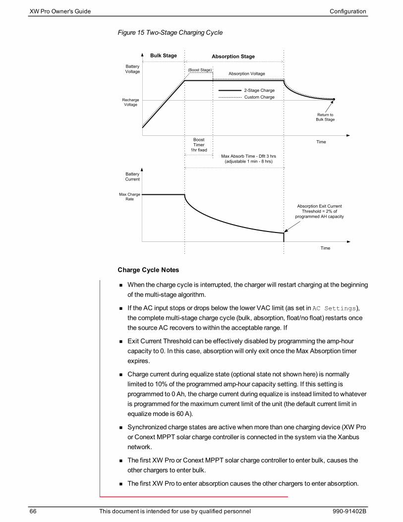
Figure 15 Two-Stage Charging Cycle
Time
Time
Absorption Voltage
Max Absorb Time - Dflt 3 hrs (adjustable 1 min - 8 hrs)
Boost Timer
1hr fixed
2-Stage ChargeCustom Charge
Absorption StageBulk Stage
(Boost Stage)
Recharge Voltage
BatteryVoltage
Battery Current
Max Charge Rate
Return to Bulk Stage
Absorption Exit Current Threshold = 2% of
programmed AH capacity
Charge Cycle Notes
n When the charge cycle is interrupted, the charger will restart charging at the beginningof themulti-stage algorithm.
n If the AC input stops or drops below the lower VAC limit (as set in AC Settings),the completemulti-stage charge cycle (bulk, absorption, float/no float) restarts oncethe source AC recovers to within the acceptable range. If
n Exit Current Threshold can be effectively disabled by programming the amp-hourcapacity to 0. In this case, absorption will only exit once theMax Absorption timerexpires.
n Charge current during equalize state (optional state not shown here) is normallylimited to 10% of the programmed amp-hour capacity setting. If this setting isprogrammed to 0 Ah, the charge current during equalize is instead limited to whateveris programmed for themaximum current limit of the unit (the default current limit inequalizemode is 60 A).
n Synchronized charge states are active whenmore than one charging device (XW Proor Conext MPPT solar charge controller is connected in the system via the Xanbusnetwork.
n The first XW Pro or Conext MPPT solar charge controller to enter bulk, causes theother chargers to enter bulk.
n The first XW Pro to enter absorption causes the other chargers to enter absorption.
XW Pro Owner's Guide Configuration
66 This document is intended for use by qualified personnel 990-91402B

n The last XW Pro ready to exit absorption triggers the rest to exit absorption and exitcharge. The XW Pro will not wait for any connected Conext MPPT solar chargecontrollers to transition to absorption or float.
Equalize ChargingMany lead acid battery manufacturers recommend periodic equalize charging to countercell charge imbalance and capacity robbing sulphation. Equalizing helps to improvebattery performance and lifespan by encouragingmore of the battery material to becomeactive.
Battery equalization is a controlled overchargingmethod that reduces sulphation andmixes up stratified electrolyte and reactivates unused areas of the plate material.Periodic equalizing can help to regularly restore flooded lead acid batteries to a healthystate of charge.
Consult the battery manufacturer's recommendation for equalize charging settings.Sealed lead acid, gel, AGM, and lithium ion batteries should not be equalized unlessrecommended by the battery manufacturer. Consult the battery manufacturer for optimalcharging procedures when using sealed batteries.
When Equalizemode is enabled, the battery is charged from bulk to absorption, and thento the equalize phase. The XW Pro will transition from the absorption phase to equalize if:
n The DC charge current is below 2% of the configured battery capacity (for example,8.8 A for 440 Ah).
n The absorption time is exceeded (for example, 180minutes).
After absorption, themaximum charge DC current is set to 10% of battery capacity (forexample, 44 A for 440 Ah). This constant current charge will continue until the voltagehas increased to the equalize voltage at which point the battery will be regulated at thetemperature compensated equalize voltage.
If the battery capacity is set to zero, the equalize charge current is fixed at maximum 44A (Ah=0 effectively disables the exit current criteria for the absorption charge stage,making the absorption stage defined by time only).
Equalization duration is fixed at one hour.
NOTE: The graphs below apply only to flooded battery types.
Configuration XW Pro Owner's Guide
990-91402B This document is intended for use by qualified personnel 67

Figure 16 Equalize Charging Grid-tie Sell Mode
Time
Time
Absorption VoltageEqualize Voltage
Max Absorb Time - Dflt 3 hrs (adjustable 1 min - 8 hrs)
Boost Timer1hr fixed
Absorption Exit Current Threshold = 2% of
programmed AH capacity
Equalize modeCustom Charge
Equalize StageAbsorption StageBulk Stage
Bulk Voltage=Boost Voltage
Battery Current
BatteryVoltage
10% of programmed AH capacity
Equalize Timer1hr fixed
XW Pro Owner's Guide Configuration
68 This document is intended for use by qualified personnel 990-91402B
Equalization Procedure
To start equalizing the batteries, do one of the following:
1. On the Charger Settings menu, toggle the Equalize Now toggle switch to Enabled.
2. Press the Equalize button on the inverter information panel for five seconds.
If the XW Pro will not perform the equalization, see WarningW96 “Cannot Equalize” inTable 23 on page 122.
WARNINGEQUALIZATION HAZARD
Only flooded lead acid batteries should be equalize charged. Hydrogen and oxygen gasesare produced when batteries are equalized and can potentially cause an explosion ifignited. Corrosive battery acid can escape.
n Provide adequate ventilation and remove all sources of ignition, such as open flames,sparks, electric motors, relays, light switches, etc.
n Equalization voltage is significantly higher than nominal battery voltage. Detachelectronics that can be damaged by high DC voltage.
Failure to follow these instructions can result in death, serious injury, or equipmentdamage.
NOTE: In a system wheremore than one device is capable of equalizing batteries (suchas a system includingmultiple XW Pro units and Conext MPPT solar charge controllers,there is no system-wide equalization command for all devices. To equalize with multipledevices, each would have to be enabled individually. Alternatively, equalization can beperformed using only one device. During the equalization process, one device applies theequalization charge while the other devices continue to operate in synchronized chargemode, typically in float (three-stage charging) or no-float (two-stage charging).
AC Settings
WARNINGADVANCED CONFIGURATION HAZARD
n Advanced menu settings should be used by qualified personnel only.
n Three phase operation should be configured by qualified personnel only.
n Consult with the local utility before enabling XW Pro sell mode or grid support functions.
n Do not change these settings unless you are under the supervision and direction ofqualified personnel.
n Connect the Conext Gateway and the network router connected to the Conext Gatewayto an assured power source during configuration.
Failure to follow these instructions can result in death, serious injury, or equipmentdamage.
Configuration XW Pro Owner's Guide
990-91402B This document is intended for use by qualified personnel 69
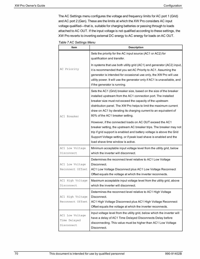
The AC Settings menu configures the voltage and frequency limits for AC port 1 (Grid)and AC port 2 (Gen). These are the limits at which the XW Pro considers AC inputvoltage qualified—that is, suitable for charging batteries or passing through to loadsattached to AC OUT. If the input voltage is not qualified according to these settings, theXW Pro reverts to inverting external DC energy to AC energy for loads on AC OUT.
Item Description
AC Priority
Sets the priority for the AC input source (AC1 or AC2) forqualification and transfer.
In systems that use both utility grid (AC1) and generator (AC2) input,it is recommended that you set AC Priority to AC1. Assuming thegenerator is intended for occasional use only, the XW Pro will useutility power. It will use the generator only if AC1 is unavailable, andif the generator is running.
AC1 Breaker
Sets the AC1 (Grid) breaker size, based on the size of the breakerinstalled upstream from the AC1 connection port. The installedbreaker size must not exceed the capacity of the upstreamdistribution panel. The XW Pro helps to limit the maximum currentdraw on AC1 by derating its charging current to an equivalent of80% of the AC1 breaker setting.
However, if the connected loads on AC OUT exceed the AC1breaker setting, the upstream AC breaker trips. The breaker may nottrip if grid support is enabled and battery voltage is above the GridSupport Voltage setting, or if peak load shave is enabled and theload shave time window is active.
AC1 Low Voltage
Disconnect
Minimum acceptable input voltage level from the utility grid, belowwhich the inverter will disconnect.
AC1 Low Voltage
Reconnect Offset
Determines the reconnect level relative to AC1 Low VoltageDisconnect.AC1 Low Voltage Disconnect plus AC1 Low Voltage ReconnectOffset equals the voltage at which the inverter reconnects.
AC1 High Voltage
Disconnect
Maximum acceptable input voltage level from the utility grid, abovewhich the inverter will disconnect.
AC1 High Voltage
Reconnect Offset
Determines the reconnect level relative to AC1 High VoltageDisconnect.AC1 High Voltage Disconnect plus AC1 High Voltage ReconnectOffset equals the voltage at which the inverter reconnects.
AC1 Low Voltage
Time Delayed
Disconnect
Input voltage level from the utility grid, below which the inverter willhave a delay of AC1 Time Delayed Disconnects Delay beforedisconnecting. This value must be higher than AC1 Low VoltageDisconnect.
Table 7 AC Settings Menu
XW Pro Owner's Guide Configuration
70 This document is intended for use by qualified personnel 990-91402B

Item Description
AC1 High Voltage
Time Delayed
Disconnect
Input voltage level from the utility grid, above which the inverter willhave a delay of AC1 Time Delayed Disconnects Delay beforedisconnecting. This value must be lower than AC1 High VoltageDisconnect.
AC1 Low
Frequency
Disconnect
Minimum acceptable utility grid input frequency, below which theinverter will disconnect.
AC1 Low
Frequency
Reconnect Offset
Determines the reconnect level relative to AC1 Low FrequencyDisconnect.AC1 Low Frequency Disconnect plus AC1 Low FrequencyReconnect Offset equals the frequency at which the inverterreconnects.
AC1 High FrequencyDisconnect
Maximum acceptable utility grid input frequency, above which theinverter will disconnect.
AC1 High FrequencyReconnect Offset
Determines the reconnect level relative to AC1 High FrequencyDisconnect.AC1 High Frequency Disconnect plus AC1 High FrequencyReconnect Offset equals the frequency at which the inverterreconnects.
AC1 Low
Frequency Time
Delayed
Disconnect
Input frequency level from the utility grid, below which the inverterwill have a delay of AC1 Time Delayed Disconnects Delay beforedisconnecting. This value must be higher than AC1 Low FrequencyDisconnect.
AC1 High FrequencyTime DelayedDisconnect
Input frequency level from the utility grid, above which the inverterwill have a delay of AC1 Time Delayed Disconnects Delay beforedisconnecting. This value must be lower than AC1 High FrequencyDisconnect.
AC1 Time DelayedDisconnects Delay
The time delay used for all AC1 time delayed voltage and frequencysetpoints.
Static OperatingReference Voltage
Sets the voltage for static effective voltage.2
AC1 Transfer SwitchDelay
The time delay between qualifying AC1 and closing its contactor.
2The following functions use effective voltage, not measured voltage: Bridge Reconnect High V,
Bridge Reconnect Low V, HVRT, LVRT, HV-CTE, LV-CTE, Q(V), P(V).
Configuration XW Pro Owner's Guide
990-91402B This document is intended for use by qualified personnel 71

Item Description
AC2 Breaker
Sets the AC2 (Gen) breaker size, based on the size of the installedAC breaker upstream from the AC2 connection port. The installedupstream breaker and the AC2 breaker set point must not exceedthe capacity of the generator. The XW Pro helps to limit themaximum current draw on AC2 by derating its charging current toan equivalent of 80% of the AC2 breaker setting.
However, if the connected loads on AC OUT exceed the AC2breaker setting, the upstream AC breaker trips. The breaker may nottrip if Gen Support is enabled and Gen Amps is configured not toexceed the generator’s rated output current.
AC2 Low Voltage
Disconnect
Minimum acceptable input voltage level from the utility grid, belowwhich the inverter will disconnect.
AC2 Low Voltage
Reconnect Offset
Determines the reconnect level relative to AC2 Low VoltageDisconnect.AC2 Low Voltage Disconnect plus AC2 Low Voltage ReconnectOffset equals the voltage at which the inverter reconnects.
AC2 High Voltage
Disconnect
Maximum acceptable input voltage level from the utility grid, abovewhich the inverter will disconnect.
AC2 High Voltage
Reconnect Offset
Determines the reconnect level relative to AC2 High VoltageDisconnect.AC2 High Voltage Disconnect plus AC2 High Voltage ReconnectOffset equals the voltage at which the inverter reconnects.
AC2 Low Voltage
Time Delayed
Disconnect
Input voltage level from the utility grid, below which the inverter willhave a delay of AC2 Time Delayed Disconnects Delay beforedisconnecting. This value must be higher than AC2 Low VoltageDisconnect.
AC2 High Voltage
Time Delayed
Disconnect
Input voltage level from the utility grid, above which the inverter willhave a delay of AC2 Time Delayed Disconnects Delay beforedisconnecting. This value must be lower than AC2 High VoltageDisconnect.
AC2 Low
Frequency
Disconnect
Minimum acceptable utility grid input frequency, below which theinverter will disconnect.
AC2 Low
Frequency
Reconnect Offset
Determines the reconnect level relative to AC2 Low FrequencyDisconnect.AC2 Low Frequency Disconnect plus AC2 Low FrequencyReconnect Offset equals the frequency at which the inverterreconnects.
AC2 High FrequencyDisconnect
Maximum acceptable utility grid input frequency, above which theinverter will disconnect.
XW Pro Owner's Guide Configuration
72 This document is intended for use by qualified personnel 990-91402B

Item Description
AC2 High FrequencyReconnect Offset
Determines the reconnect level relative to AC2 High FrequencyDisconnect.AC2 High Frequency Disconnect plus AC2 High FrequencyReconnect Offset equals the frequency at which the inverterreconnects.
AC2 Low
Frequency Time
Delayed
Disconnect
Input frequency level from the utility grid, below which the inverterwill have a delay of AC2 Time Delayed Disconnects Delay beforedisconnecting. This value must be higher than AC2 Low FrequencyDisconnect.
AC2 High FrequencyTime DelayedDisconnect
Input frequency level from the utility grid, above which the inverterwill have a delay of AC2 Time Delayed Disconnects Delay beforedisconnecting. This value must be lower than AC2 High FrequencyDisconnect.
AC2 Time DelayedDisconnects Delay
The time delay used for all AC2 time delayed voltage and frequencysetpoints.
AC2 Transfer SwitchDelay
The time delay between qualifying AC2 and closing its contactor.
External ContactorMismatch Fault Delay
The trip time needed to activate fault F72 if the external contactorcommand does not match the actual status of the external contactor.Adjust this parameter to account for varying close and openingtimes of the contactors available for use.
Inverter to GridOverlap
The time delay from closing the external contactor (if equipped) dueto grid qualification to exiting grid-forming operation. Depending onthe external contactor installed, this value must be tuned toaccommodate its closing time reliably. By default, this value is set to0.015 seconds.
Grid to Invert Delay
The time delay from opening the external contactor (if equipped)due to a grid outage to grid-forming operation. Depending on theexternal contactor installed, this value must be tuned toaccommodate its opening time reliably. By default, this value is setto 0.1 seconds.
For default settings, see "AC Settings Menu" on page 148.
Configuring Nominal Grid Frequency
This adjustment is performed by selecting the appropriate compliance region for eachXW Pro. For instance, by selecting Australia, the unit being configured will adopt a 50 Hznominal grid frequency. All frequency-related functions, including over/underfrequencydetection, are based upon these settings. Refer to "Managing Compliance Regions" onpage 99 for information on how to select a compliance region.
Grid Support SettingsTheGrid Support Settings menu contains configuration options for grid-tie operation. Toenable these settings, Grid Support must be enabled in the Grid Support menu. Individual
Configuration XW Pro Owner's Guide
990-91402B This document is intended for use by qualified personnel 73
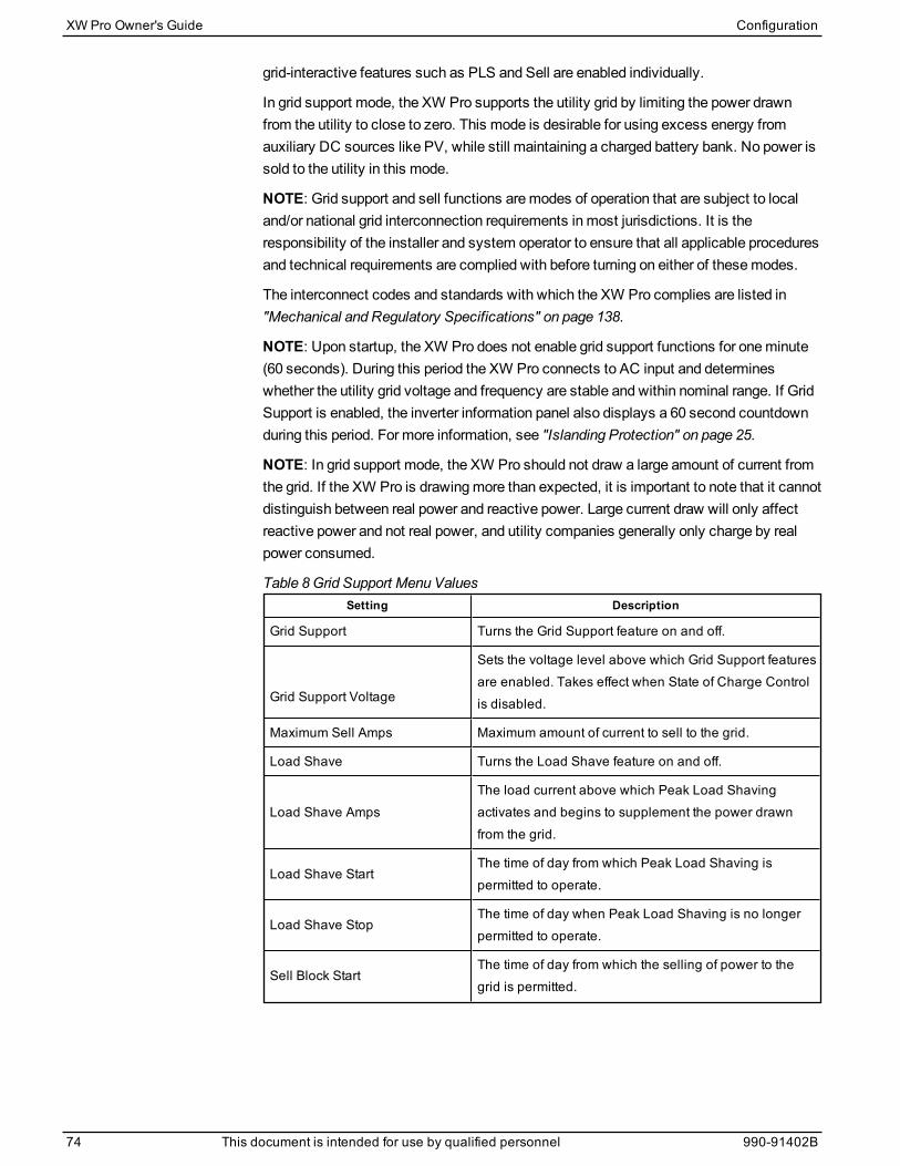
grid-interactive features such as PLS and Sell are enabled individually.
In grid support mode, the XW Pro supports the utility grid by limiting the power drawnfrom the utility to close to zero. This mode is desirable for using excess energy fromauxiliary DC sources like PV, while still maintaining a charged battery bank. No power issold to the utility in this mode.
NOTE: Grid support and sell functions aremodes of operation that are subject to localand/or national grid interconnection requirements in most jurisdictions. It is theresponsibility of the installer and system operator to ensure that all applicable proceduresand technical requirements are complied with before turning on either of thesemodes.
The interconnect codes and standards with which the XW Pro complies are listed in"Mechanical and Regulatory Specifications" on page 138.
NOTE: Upon startup, the XW Pro does not enable grid support functions for oneminute(60 seconds). During this period the XW Pro connects to AC input and determineswhether the utility grid voltage and frequency are stable and within nominal range. If GridSupport is enabled, the inverter information panel also displays a 60 second countdownduring this period. For more information, see "Islanding Protection" on page 25.
NOTE: In grid support mode, the XW Pro should not draw a large amount of current fromthe grid. If the XW Pro is drawingmore than expected, it is important to note that it cannotdistinguish between real power and reactive power. Large current draw will only affectreactive power and not real power, and utility companies generally only charge by realpower consumed.
Setting Description
Grid Support Turns the Grid Support feature on and off.
Grid Support Voltage
Sets the voltage level above which Grid Support featuresare enabled. Takes effect when State of Charge Controlis disabled.
Maximum Sell Amps Maximum amount of current to sell to the grid.
Load Shave Turns the Load Shave feature on and off.
Load Shave AmpsThe load current above which Peak Load Shavingactivates and begins to supplement the power drawnfrom the grid.
Load Shave StartThe time of day from which Peak Load Shaving ispermitted to operate.
Load Shave StopThe time of day when Peak Load Shaving is no longerpermitted to operate.
Sell Block StartThe time of day from which the selling of power to thegrid is permitted.
Table 8 Grid Support Menu Values
XW Pro Owner's Guide Configuration
74 This document is intended for use by qualified personnel 990-91402B
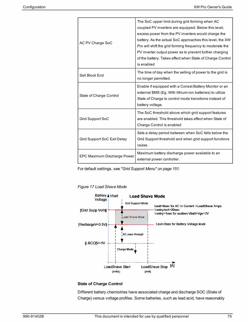
AC PV Charge SoC
The SoC upper limit during grid forming when ACcoupled PV inverters are equipped. Below this level,excess power from the PV inverters would charge thebattery. As the actual SoC approaches this level, the XWPro will shift the grid forming frequency to moderate thePV inverter output power as to prevent further chargingof the battery. Takes effect when State of Charge Controlis enabled
Sell Block EndThe time of day when the selling of power to the grid isno longer permitted.
State of Charge Control
Enable if equipped with a Conext Battery Monitor or anexternal BMS (Eg. With lithium-ion batteries) to utilizeState of Charge to control mode transitions instead ofbattery voltage.
Grid Support SoCThe SoC threshold above which grid support featuresare enabled. This threshold takes effect when State ofCharge Control is enabled
Grid Support SoC Exit DelaySets a delay period between when SoC falls below theGrid Support threshold and when grid support functionscease.
EPC Maximum Discharge PowerMaximum battery discharge power available to anexternal power controller.
For default settings, see "Grid Support Menu" on page 151.
Figure 17 Load ShaveMode
State of Charge Control
Different battery chemistries have associated charge and discharge SOC (State ofCharge) versus voltage profiles. Some batteries, such as lead acid, have reasonably
Configuration XW Pro Owner's Guide
990-91402B This document is intended for use by qualified personnel 75
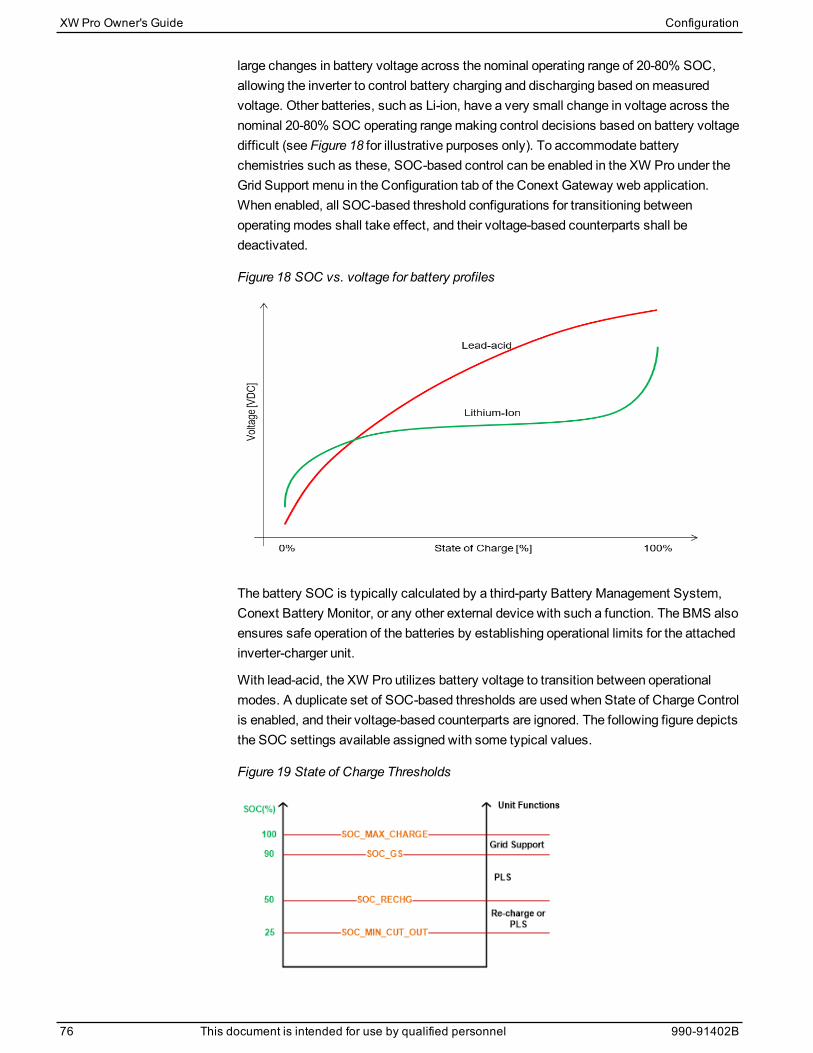
large changes in battery voltage across the nominal operating range of 20-80% SOC,allowing the inverter to control battery charging and discharging based onmeasuredvoltage. Other batteries, such as Li-ion, have a very small change in voltage across thenominal 20-80% SOC operating rangemaking control decisions based on battery voltagedifficult (see Figure 18 for illustrative purposes only). To accommodate batterychemistries such as these, SOC-based control can be enabled in the XW Pro under theGrid Support menu in the Configuration tab of the Conext Gateway web application.When enabled, all SOC-based threshold configurations for transitioning betweenoperatingmodes shall take effect, and their voltage-based counterparts shall bedeactivated.
Figure 18 SOC vs. voltage for battery profiles
The battery SOC is typically calculated by a third-party Battery Management System,Conext Battery Monitor, or any other external device with such a function. The BMS alsoensures safe operation of the batteries by establishing operational limits for the attachedinverter-charger unit.
With lead-acid, the XW Pro utilizes battery voltage to transition between operationalmodes. A duplicate set of SOC-based thresholds are used when State of Charge Controlis enabled, and their voltage-based counterparts are ignored. The following figure depictsthe SOC settings available assigned with some typical values.
Figure 19 State of Charge Thresholds
XW Pro Owner's Guide Configuration
76 This document is intended for use by qualified personnel 990-91402B

Generator Support Settings
WARNINGADVANCED CONFIGURATION HAZARD
n Advanced menu settings should be used by qualified personnel only.
n Three phase operation should be configured by qualified personnel only.
n Consult with the local utility before enabling XW Pro sell mode or grid support functions.
n Do not change these settings unless you are under the supervision and direction ofqualified personnel.
n Connect the Conext Gateway and the network router connected to the Conext Gatewayto an assured power source during configuration.
Failure to follow these instructions can result in death, serious injury, or equipmentdamage.
Generator support allows power to be automatically drawn from the batteries to assist anAC generator on AC2 to support heavy loads on AC OUT (loads that exceed theavailable power from the generator).
Generators have a limited output current and it is possible to reach this limit whenoperating heavy loads. The XW Pro is designed to assist the generator when heavycurrent demands load down the generator by supplying additional power from thebatteries.
In addition, the battery charger can reduce its charging current to the batteries so thecombined AC current required for charging and the total load current do not exceed thecapacity of the generator or trip its output breakers or fuses.
For imbalanced loads and small generators, the generator support featuremay be used.WhenGenerator Support Plus is enabled, the XW Pro will connect the center of itstransformer to the AC2 input neutral to act as a load balancing transformer. This featurewill attempt to balance the load between L1 and L2. Generator support is most effectivefor generators under 5 kW. See "Advanced Features" on page 85.
NOTE: The passthrough running and startup (peak) currents of generators attached toAC2 are limited to themaximum current limits of the XW Pro.
NOTE: If generator support is used with generators larger than 5 kW, it is possible forcurrent to recirculate. In this case, the efficiency losses would outweigh the benefit ofgenerator support.
Configuration XW Pro Owner's Guide
990-91402B This document is intended for use by qualified personnel 77
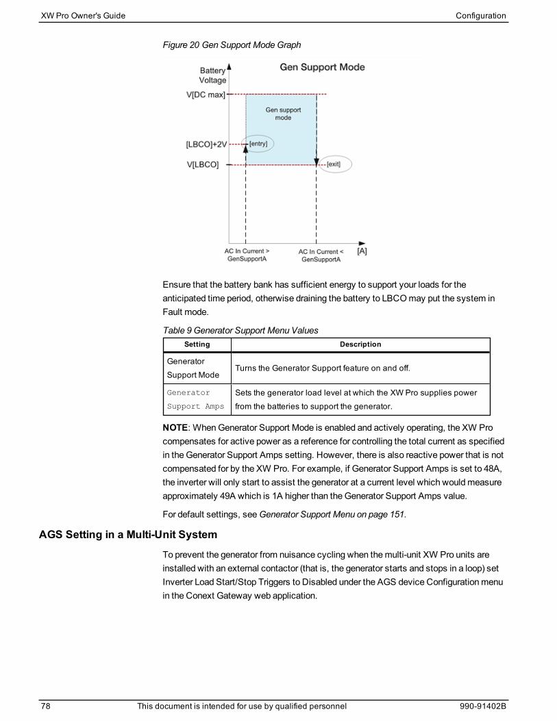
Figure 20 Gen Support ModeGraph
Ensure that the battery bank has sufficient energy to support your loads for theanticipated time period, otherwise draining the battery to LBCOmay put the system inFault mode.
Setting Description
GeneratorSupport Mode
Turns the Generator Support feature on and off.
Generator
Support Amps
Sets the generator load level at which the XW Pro supplies powerfrom the batteries to support the generator.
Table 9 Generator Support Menu Values
NOTE: WhenGenerator Support Mode is enabled and actively operating, the XW Procompensates for active power as a reference for controlling the total current as specifiedin the Generator Support Amps setting. However, there is also reactive power that is notcompensated for by the XW Pro. For example, if Generator Support Amps is set to 48A,the inverter will only start to assist the generator at a current level which wouldmeasureapproximately 49A which is 1A higher than the Generator Support Amps value.
For default settings, seeGenerator Support Menu on page 151.
AGS Setting in a Multi-Unit SystemTo prevent the generator from nuisance cycling when themulti-unit XW Pro units areinstalled with an external contactor (that is, the generator starts and stops in a loop) setInverter Load Start/Stop Triggers to Disabled under the AGS device Configurationmenuin the Conext Gateway web application.
XW Pro Owner's Guide Configuration
78 This document is intended for use by qualified personnel 990-91402B
Auxiliary Output Settings
WARNINGADVANCED CONFIGURATION HAZARD
n Advanced menu settings should be used by qualified personnel only.
n Three phase operation should be configured by qualified personnel only.
n Consult with the local utility before enabling XW Pro sell mode or grid support functions.
n Do not change these settings unless you are under the supervision and direction ofqualified personnel.
n Connect the Conext Gateway and the network router connected to the Conext Gatewayto an assured power source during configuration.
Failure to follow these instructions can result in death, serious injury, or equipmentdamage.
The Aux menu allows you to enable and set the auxiliary output. The auxiliary outputprovides 12 volts DC at 250milliamps to power a relay, indicator light, or alarm.
NOTE: Changing Auxiliary Output Trigger Level resets the auxiliary output. If an auxiliaryoutput trigger is active, changing the trigger level will clear the trigger.
For default settings, see "Auxiliary Menu" on page 152.
Setting Description
Auxiliary Output
Active Level
Sets the mode (polarity) of the auxiliary output. When triggered,the output can be active high (12 V output turns on) or activelow (output is high until the trigger turns it off).
Auxiliary Output
Trigger Source
Selects the desired condition (trigger source) to activate theauxiliary output.
Table 10 Auxiliary Menu Values
The following parameter set controls the activation and de-activation conditions for theAuxiliary Output and are available for each trigger source.
Setting Description
Trigger Set
Sets the voltage or temperature level (depending on theselected trigger source) at which the auxiliary output isactivated. If the selected Trigger Source is a battery voltage, therange also varies according to the nominal battery voltage ofyour system.
Trigger Set
Delay
Sets a delay period between when the trigger occurs and whenthe auxiliary output is activated.
Trigger Clear
Sets the voltage or temperature level (depending on theselected trigger source) at which the auxiliary output becomesinactive.
Table 11 Auxiliary Menu Values
Configuration XW Pro Owner's Guide
990-91402B This document is intended for use by qualified personnel 79
Setting Description
Trigger Clear
Delay
Sets a delay period between when the Trigger Clear settingoccurs and when the auxiliary output becomes inactive.
Trigger Source Descriptions
Low Battery Voltage
Activates the auxiliary output when the battery voltage fallsbelow Low Battery Voltage after the trigger delay time. Theauxiliary output turns off when the battery voltage rises abovethe clear setting after the Clear Delay time. Use this setting ifthe auxiliary output needs to control a relay to disconnect loadsfrom a battery or to activate a low battery voltage alarm such asa buzzer or light.
High Battery Voltage
Activates the auxiliary output when the battery voltage risesabove High Battery Voltage for the trigger delay time. Theauxiliary output turns off when the battery voltage falls belowthe clear setting for the Clear Delay time. This setting is usefulfor:
n Installations that have another external charging sourcesuch as a wind generator or hydro generator connecteddirectly to the batteries. The XW Pro auxiliary output cancontrol a relay to disconnect the external charging sourcefrom the battery or control a relay to turn on a diversionload.
n Activating a high battery voltage alarm such as a buzzer orlight.
n Activating a vent fan to ventilate the battery compartment.
Low BatteryTemperature
Activates the auxiliary output when the battery temperature fallsbelow Low Battery Temperature for the trigger delay time. Theauxiliary output turns off when the battery temperature risesabove the clear setting for the Clear Delay time. Batterytemperature is measured with a battery temperature sensor. Donot use this setting if a battery temperature sensor is notinstalled.
High BatteryTemperature
Activates the auxiliary output when the battery temperaturerises above High Battery Temperature for the trigger delaytime. The auxiliary output turns off when the batterytemperature falls below the clear setting for the Clear Delaytime. Battery temperature is measured with a batterytemperature sensor. Do not use this setting if a batterytemperature sensor is not installed. With this setting, theauxiliary output can turn on a fan to vent the batterycompartment.
Table 12 Trigger Source Descriptions
XW Pro Owner's Guide Configuration
80 This document is intended for use by qualified personnel 990-91402B

Heat SinkOvertemperature
Activates the auxiliary output when the heat sink temperatureexceeds its trigger set for longer than its set delay. Theauxiliary output turns off when the temperature falls below itsclear threshold for longer than its clear delay.
Bulk Exit
Exits charge bulk mode. In charge bulk mode, the XW Prooperates as a constant power source to the battery bank. Theaux port clears its state when the inverter exits from Bulkcharge stage.
Absorption Exit
Exits charge absorption mode and starts the following mode,depending on whether the unit is set to two or three-stagecharge. The aux port clears its state when the inverter exitsfrom Absorption charge stage.
FaultActivates the auxiliary output when a fault occurs. The auxiliaryoutput clears when the fault is cleared.
Battery Low State ofCharge
This feature works in conjunction with the Conext BatteryMonitor or an external BMS. This auxiliary output is triggeredwhen the state of charge falls outside of the range of 25-90% oftotal battery charge.
Time of Day
When Time of Day is selected as a trigger source, the TriggerBlock Start and Block End become available. Both can be setto a value between 12:00 AM and 11:59 PM.
Block Start is when the Auxiliary Output goes into inactive state.Block End is when the Auxiliary Output goes into active state.
Configuration XW Pro Owner's Guide
990-91402B This document is intended for use by qualified personnel 81
Multi-Unit Configuration Menu
WARNINGADVANCED CONFIGURATION HAZARD
n Advanced menu settings should be used by qualified personnel only.
n Three phase operation should be configured by qualified personnel only.
n Consult with the local utility before enabling XW Pro sell mode or grid support functions.
n Do not change these settings unless you are under the supervision and direction ofqualified personnel.
n Connect the Conext Gateway and the network router connected to the Conext Gatewayto an assured power source during configuration.
Failure to follow these instructions can result in death, serious injury, or equipmentdamage.
TheMulti-Unit Config menu configures the XW Pro to operate as a part of amulti-unitinstallation.
When installing amulti-unit system, each setting on theMulti-Unit Config menu (exceptfor Dev Name)must be configured for each XW Pro in the system. The settings shouldbe configured in the following order:
n Dev Number (see "Device InstanceMenu" on page 157)
n Inverter Mode (see table below)
n Associations (see "Associations Menu" on page 154)
XW Pro Owner's Guide Configuration
82 This document is intended for use by qualified personnel 990-91402B

Item Description Default Range
Inverter
Mode
For a multi-unit system tooperate in single and splitconfigurations, one XW Promust be configured to Masterand the rest as Slave,otherwise a system-wide faultis asserted.
For multi-cluster two or threephase systems, only onemulti-phase cluster is to becomprised of Masters of theirrespective phases (Phase 1Master, Phase 2 Master,Phase 3 Master), and theremaining clusters as Slavesof their respective phases(Phase 1 Slave, Phase 2Slave, Phase 3 Slave).
SplitPhaseMaster
Invalid
Single Phase
Stand Alone
Master
Slave
Split Phase
Stand Alone
Master
Slave
Two Phase
Phase 1 Master
Phase 1 Slave
Phase 2 Master
Phase 2 Slave
Three Phase
Stand Alone
Master
Slave
Phase 1 Master
Phase 1 Slave
Phase 2 Master
Phase 2 Slave
Phase 3 Master
Phase 3 Slave
Table 13 Multi-Unit ConfigurationMenu
For default settings, see "Multi-unit ConfigurationMenu" on page 154.
Configuration XW Pro Owner's Guide
990-91402B This document is intended for use by qualified personnel 83

Associations Settings
WARNINGADVANCED CONFIGURATION HAZARD
n Advanced menu settings should be used by qualified personnel only.
n Three phase operation should be configured by qualified personnel only.
n Consult with the local utility before enabling XW Pro sell mode or grid support functions.
n Do not change these settings unless you are under the supervision and direction ofqualified personnel.
n Connect the Conext Gateway and the network router connected to the Conext Gatewayto an assured power source during configuration.
Failure to follow these instructions can result in death, serious injury, or equipmentdamage.
The Associations menu contains additional settings to allow the XW Pro to function aspart of a multi-unit networked system.
Setting the connections for a Xanbus-enabled device provides a way of identifying non-network associations for Xanbus-enabled devices and enhancing networked powersystemmanagement. When connections are set, devices of different types becomeassociated and can share sources, e.g. a commonDC input source, or a commongrid/generator source.
In multi-unit networked systems, multiple inverter/chargers can be stacked to produceincreased charge current. To achieve this functionality, the devices must be configuredto the sameDC connection, such as House Battery Bank 1. The units will collaborate onbattery charging by communicating with other units on this shared DC connection.
NOTE: When configuring clusters of three XW Pro units (or a grouping of up to six in agrid-tie application), each cluster’s DC connections must be set to the same batterybank. If one of the units is set with a different DC connection, a system configurationfault (F66) occurs.
Item Description
BatteryAssociation
DC input and output connection. This is the common DC connectionshared between the XW Pro, charge controllers, and referenced by theConext AGS.
AC OutputAssociation(Loads)
AC output connection. This connection specifies a common AC outputconnection shared between XW Pro units. The AC output connection hasto be configured so that the units know if they are connected to the sameload or not. If connected to the same load, select the same name on allunits; for example, “ACLoad1.” If connected to separate load banks, usedifferent names for the AC output connection on each unit; for example,“ACLoad1” on one unit and “ACLoad2” on the other.
Table 14 Associations Menu
XW Pro Owner's Guide Configuration
84 This document is intended for use by qualified personnel 990-91402B

Item Description
AC1Association(Grid)
AC1 input connection. This connection specifies a common AC port 1input for multiple XW Pro units.
AC2Association(Generator)
AC2 input connection. This connection specifies a common AC port 2input for multiple XW Pro units.
For default settings, see "Associations Menu" on page 154.
Figure 21 XW Pro Connections Representation
L1 NAC
LOADGRID (AC1)
GEN (AC2)
AC OUT AC IN AC IN
L1 N L1 N
1 3
4
2
1 AC Out Connection: Select AC Load 1 to 10
2 AC1 Connection: Select Grid 1 to 10, Generator 1 to 10
3 DC Connection: Select House Battery Bank 1 to 5
4 AC2 Connection: Select Grid 1 to 10, Generator 1 to 10
Advanced Features
WARNINGADVANCED CONFIGURATION HAZARD
n Advanced menu settings should be used by qualified personnel only.
n Three phase operation should be configured by qualified personnel only.
n Consult with the local utility before enabling XW Pro sell mode or grid support functions.
n Do not change these settings unless you are under the supervision and direction ofqualified personnel.
n Connect the Conext Gateway and the network router connected to the Conext Gatewayto an assured power source during configuration.
Failure to follow these instructions can result in death, serious injury, or equipmentdamage.
Configuration XW Pro Owner's Guide
990-91402B This document is intended for use by qualified personnel 85
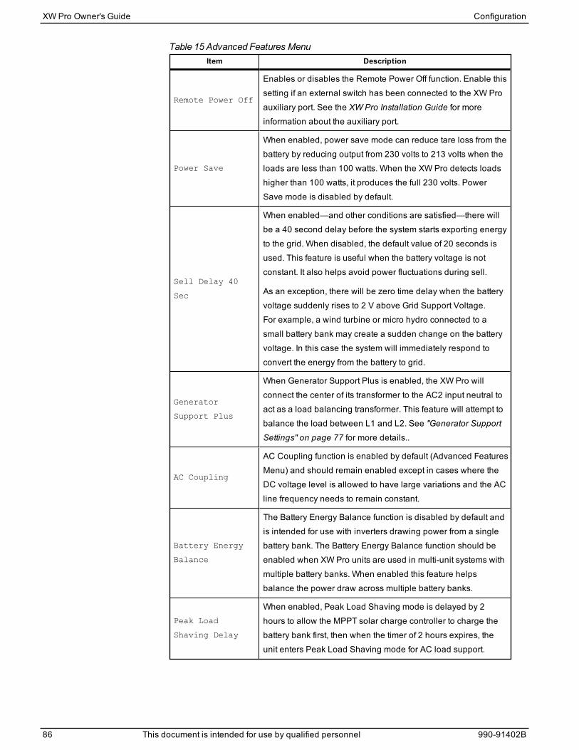
Item Description
Remote Power Off
Enables or disables the Remote Power Off function. Enable thissetting if an external switch has been connected to the XW Proauxiliary port. See the XW Pro Installation Guide for moreinformation about the auxiliary port.
Power Save
When enabled, power save mode can reduce tare loss from thebattery by reducing output from 230 volts to 213 volts when theloads are less than 100 watts. When the XW Pro detects loadshigher than 100 watts, it produces the full 230 volts. PowerSave mode is disabled by default.
Sell Delay 40
Sec
When enabled—and other conditions are satisfied—there willbe a 40 second delay before the system starts exporting energyto the grid. When disabled, the default value of 20 seconds isused. This feature is useful when the battery voltage is notconstant. It also helps avoid power fluctuations during sell.
As an exception, there will be zero time delay when the batteryvoltage suddenly rises to 2 V above Grid Support Voltage.For example, a wind turbine or micro hydro connected to asmall battery bank may create a sudden change on the batteryvoltage. In this case the system will immediately respond toconvert the energy from the battery to grid.
Generator
Support Plus
When Generator Support Plus is enabled, the XW Pro willconnect the center of its transformer to the AC2 input neutral toact as a load balancing transformer. This feature will attempt tobalance the load between L1 and L2. See "Generator SupportSettings" on page 77 for more details..
AC Coupling
AC Coupling function is enabled by default (Advanced FeaturesMenu) and should remain enabled except in cases where theDC voltage level is allowed to have large variations and the ACline frequency needs to remain constant.
Battery Energy
Balance
The Battery Energy Balance function is disabled by default andis intended for use with inverters drawing power from a singlebattery bank. The Battery Energy Balance function should beenabled when XW Pro units are used in multi-unit systems withmultiple battery banks. When enabled this feature helpsbalance the power draw across multiple battery banks.
Peak Load
Shaving Delay
When enabled, Peak Load Shaving mode is delayed by 2hours to allow the MPPT solar charge controller to charge thebattery bank first, then when the timer of 2 hours expires, theunit enters Peak Load Shaving mode for AC load support.
Table 15 Advanced Features Menu
XW Pro Owner's Guide Configuration
86 This document is intended for use by qualified personnel 990-91402B
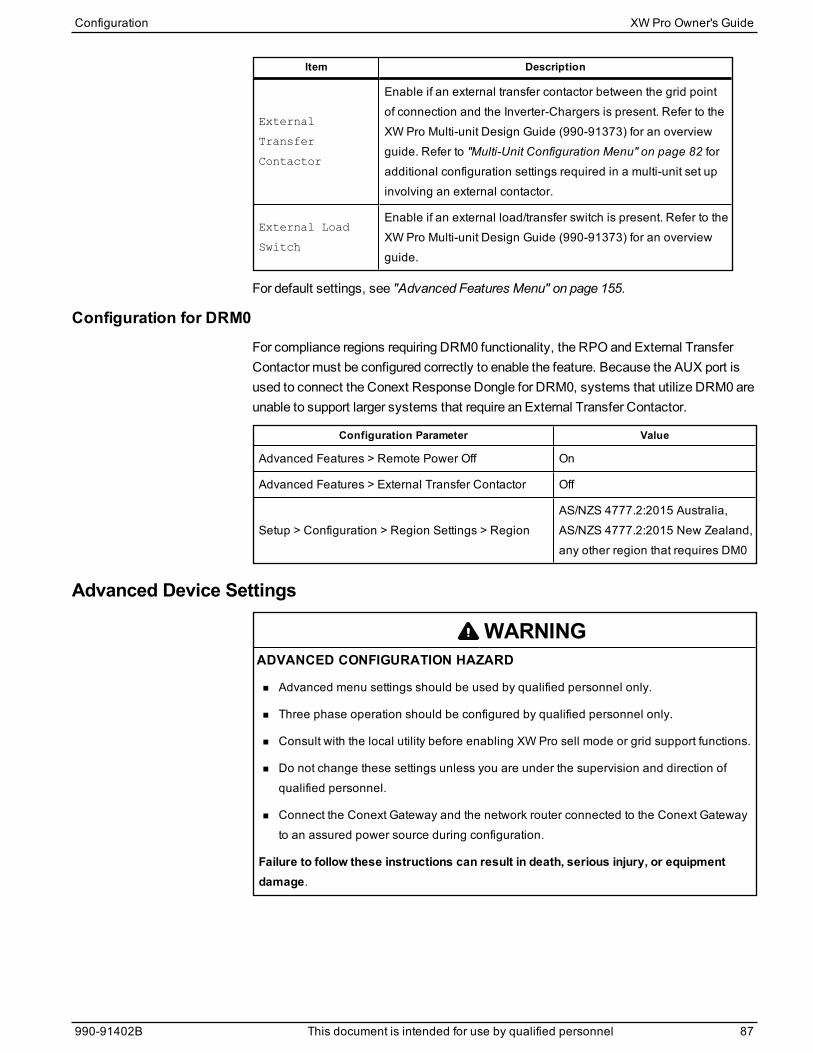
Item Description
External
Transfer
Contactor
Enable if an external transfer contactor between the grid pointof connection and the Inverter-Chargers is present. Refer to theXW Pro Multi-unit Design Guide (990-91373) for an overviewguide. Refer to "Multi-Unit Configuration Menu" on page 82 foradditional configuration settings required in a multi-unit set upinvolving an external contactor.
External Load
Switch
Enable if an external load/transfer switch is present. Refer to theXW Pro Multi-unit Design Guide (990-91373) for an overviewguide.
For default settings, see "Advanced Features Menu" on page 155.
Configuration for DRM0For compliance regions requiring DRM0 functionality, the RPO and External TransferContactor must be configured correctly to enable the feature. Because the AUX port isused to connect the Conext Response Dongle for DRM0, systems that utilize DRM0 areunable to support larger systems that require an External Transfer Contactor.
Configuration Parameter Value
Advanced Features > Remote Power Off On
Advanced Features > External Transfer Contactor Off
Setup > Configuration > Region Settings > RegionAS/NZS 4777.2:2015 Australia,AS/NZS 4777.2:2015 New Zealand,any other region that requires DM0
Advanced Device Settings
WARNINGADVANCED CONFIGURATION HAZARD
n Advanced menu settings should be used by qualified personnel only.
n Three phase operation should be configured by qualified personnel only.
n Consult with the local utility before enabling XW Pro sell mode or grid support functions.
n Do not change these settings unless you are under the supervision and direction ofqualified personnel.
n Connect the Conext Gateway and the network router connected to the Conext Gatewayto an assured power source during configuration.
Failure to follow these instructions can result in death, serious injury, or equipmentdamage.
Configuration XW Pro Owner's Guide
990-91402B This document is intended for use by qualified personnel 87
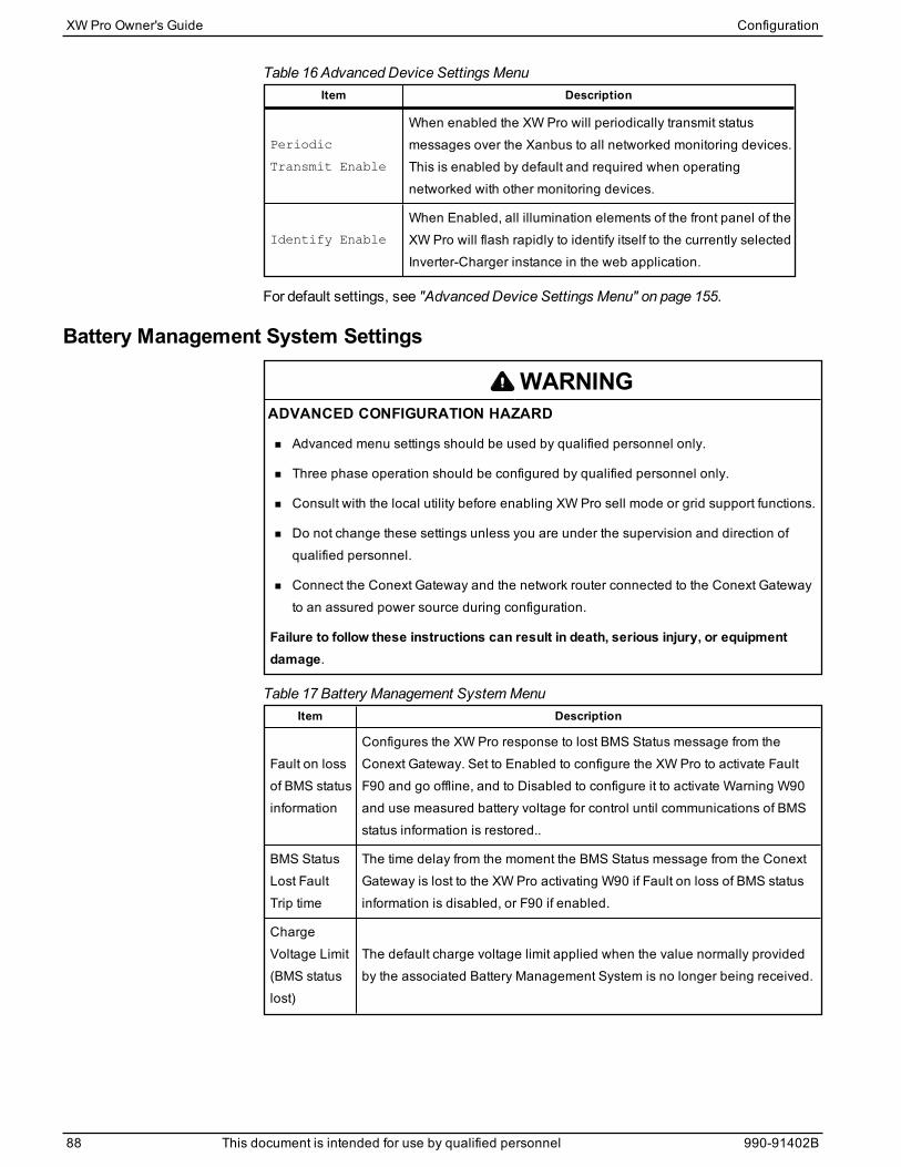
Item Description
Periodic
Transmit Enable
When enabled the XW Pro will periodically transmit statusmessages over the Xanbus to all networked monitoring devices.This is enabled by default and required when operatingnetworked with other monitoring devices.
Identify Enable
When Enabled, all illumination elements of the front panel of theXW Pro will flash rapidly to identify itself to the currently selectedInverter-Charger instance in the web application.
Table 16 Advanced Device Settings Menu
For default settings, see "Advanced Device Settings Menu" on page 155.
Battery Management System Settings
WARNINGADVANCED CONFIGURATION HAZARD
n Advanced menu settings should be used by qualified personnel only.
n Three phase operation should be configured by qualified personnel only.
n Consult with the local utility before enabling XW Pro sell mode or grid support functions.
n Do not change these settings unless you are under the supervision and direction ofqualified personnel.
n Connect the Conext Gateway and the network router connected to the Conext Gatewayto an assured power source during configuration.
Failure to follow these instructions can result in death, serious injury, or equipmentdamage.
Item Description
Fault on lossof BMS statusinformation
Configures the XW Pro response to lost BMS Status message from theConext Gateway. Set to Enabled to configure the XW Pro to activate FaultF90 and go offline, and to Disabled to configure it to activate Warning W90and use measured battery voltage for control until communications of BMSstatus information is restored..
BMS StatusLost FaultTrip time
The time delay from the moment the BMS Status message from the ConextGateway is lost to the XW Pro activating W90 if Fault on loss of BMS statusinformation is disabled, or F90 if enabled.
ChargeVoltage Limit(BMS statuslost)
The default charge voltage limit applied when the value normally providedby the associated Battery Management System is no longer being received.
Table 17 Battery Management SystemMenu
XW Pro Owner's Guide Configuration
88 This document is intended for use by qualified personnel 990-91402B

DischargeVoltage Limit(BMS statuslost)
The default discharge voltage limit applied when the value normallyprovided by the associated Battery Management System is no longer beingreceived.
ChargeCurrent Limit(BMS statuslost)
The default charge current limit applied when the value normally providedby the associated Battery Management System is no longer being received.
DischargeCurrent Limit(BMS statuslost)
The default discharge current limit applied when the value normallyprovided by the associated Battery Management System is no longer beingreceived.
ChargeOvercurrentOffset
Offset added to the charge overcurrent limit broadcasted by the associatedBMS. The resulting threshold becomes the XW Pro’s own chargeovercurrent limit.
ChargeOvercurrentTrip Time
The time delay from the moment charge current exceeds the thresholddetermined above until the XW Pro activates fault F73.
DischargeOvercurrentOffset
Offset added to the discharge overcurrent limit broadcasted by theassociated BMS. The resulting threshold becomes the XW Pro’s owndischarge overcurrent limit.
DischargeOvercurrentTrip Time
The time delay from the moment discharge current exceeds the thresholddetermined above until the XW Pro activates fault F71.
DCUndervoltageOffset
Offset added to the undervoltage limit broadcasted by the associated BMS.The resulting threshold becomes the XW Pro’s own undervoltage limit.
DCUndervoltageTrip Time
The time delay from the moment battery voltage exceeds the thresholddetermined above until the XW Pro activates fault F74.
DCOvervoltageOffset
Offset added to the overvoltage limit broadcasted by the associated BMS.The resulting threshold becomes the XW Pro’s own overvoltage limit.
DCOvervoltageTrip Time
The time delay from the moment battery voltage exceeds the thresholddetermined above until the XW Pro activates fault F75.
Fault on lossof State ofChargeinformation
Configures the XW Pro response to lost BMS State of Charge fromtheConext Gateway. Set to Enabled to configure the XW Pro to go offline,and to Disabled to configure it to use measured battery voltage for control.
For default settings, see "Battery Management Systems Menu" on page 156.
Configuration XW Pro Owner's Guide
990-91402B This document is intended for use by qualified personnel 89
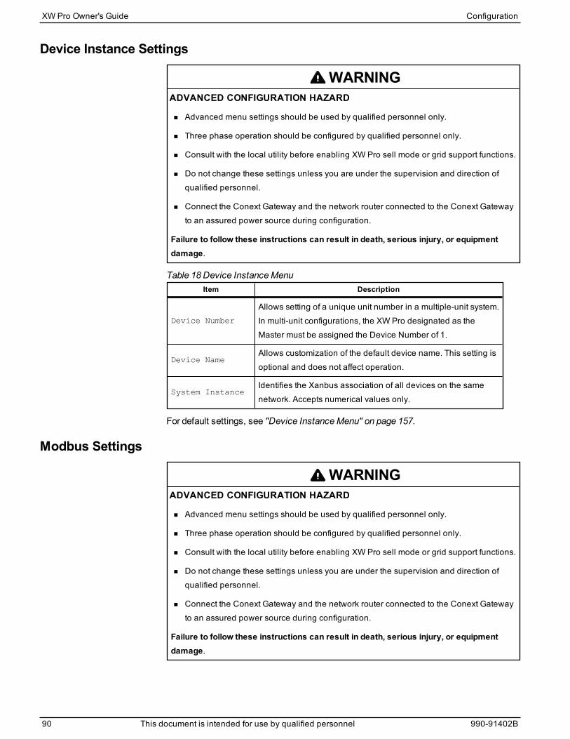
Device Instance Settings
WARNINGADVANCED CONFIGURATION HAZARD
n Advanced menu settings should be used by qualified personnel only.
n Three phase operation should be configured by qualified personnel only.
n Consult with the local utility before enabling XW Pro sell mode or grid support functions.
n Do not change these settings unless you are under the supervision and direction ofqualified personnel.
n Connect the Conext Gateway and the network router connected to the Conext Gatewayto an assured power source during configuration.
Failure to follow these instructions can result in death, serious injury, or equipmentdamage.
Item Description
Device Number
Allows setting of a unique unit number in a multiple-unit system.In multi-unit configurations, the XW Pro designated as theMaster must be assigned the Device Number of 1.
Device NameAllows customization of the default device name. This setting isoptional and does not affect operation.
System InstanceIdentifies the Xanbus association of all devices on the samenetwork. Accepts numerical values only.
Table 18 Device InstanceMenu
For default settings, see "Device InstanceMenu" on page 157.
Modbus Settings
WARNINGADVANCED CONFIGURATION HAZARD
n Advanced menu settings should be used by qualified personnel only.
n Three phase operation should be configured by qualified personnel only.
n Consult with the local utility before enabling XW Pro sell mode or grid support functions.
n Do not change these settings unless you are under the supervision and direction ofqualified personnel.
n Connect the Conext Gateway and the network router connected to the Conext Gatewayto an assured power source during configuration.
Failure to follow these instructions can result in death, serious injury, or equipmentdamage.
XW Pro Owner's Guide Configuration
90 This document is intended for use by qualified personnel 990-91402B

Item Description
Modbus Slave
Address (Port
502)
Port 502 is the Sunspec-compliant port for all Sunspec devices.The default address is 10.
Modbus Slave
Address (Port
503)
Port 503 is used for all other Modbus devices, including legacydevices. The default address is 10.
Table 19 Modbus Settings Menu
For default settings, see "Modbus Settings Menu" on page 157.
Configuration XW Pro Owner's Guide
990-91402B This document is intended for use by qualified personnel 91
Prioritizing and Managing Energy Sources with Advanced FeaturesThe XW Pro can be programmed to control how and when to use utility power as well asexternal DC sources of energy such as batteries and solar charge controllers. Advancedfeatures allow management of peak loads, time-of-use billing and self consumption.
Grid Support
WARNINGADVANCED CONFIGURATION HAZARD
n Advanced menu settings should be used by qualified personnel only.
n Three phase operation should be configured by qualified personnel only.
n Consult with the local utility before enabling XW Pro sell mode or grid support functions.
n Do not change these settings unless you are under the supervision and direction ofqualified personnel.
n Connect the Conext Gateway and the network router connected to the Conext Gatewayto an assured power source during configuration.
Failure to follow these instructions can result in death, serious injury, or equipmentdamage.
NOTE: Grid support and sell functions aremodes of operation that are subject to localand/or national grid interconnection requirements in most jurisdictions. It is theresponsibility of the installer and system operator to ensure that all applicable proceduresand technical requirements are complied with before turning on either of thesemodes.The interconnect codes and standards with which the XW Pro complies are listed inSpecifications.
The grid support mode allows the XW Pro to support local loads by converting excesscapacity from external DC sources connected to its battery bank. Examples of externalDC sources are solar charge controllers and batteries.
For Grid Support to function, Grid Support must be enabled on theGrid Support menu andeither the battery voltagemust be above theGrid Support Voltage setting or SoC must beaboveGrid Support SoC setting, depending on whether or not State of Charge Control isenabled.".
There are twomodes of operation within Grid Support.
Grid Support Enabled, Sell Disabled
In this mode, available excess DC power is converted and used to power local loads. Nopower is exported to the utility. If the local load demand exceeds the available power fromthe external DC sources, power is then drawn from the utility to support the load.However, if the local load demand is less than the power available from external DCsources, the net excess power from the external DC sources is not converted and hencenot used.
XW Pro Owner's Guide Configuration
92 This document is intended for use by qualified personnel 990-91402B
Grid Support Enabled, Sell Enabled
In this mode, all available excess DC power is first used to power local loads. Anyremaining power is exported to the utility grid.
Note: To comply with anti-islanding requirements, in a grid tied AC coupled system,change the AC1 Transfer Delay setting under AC Transfer Configuration to300 seconds.
Sell Block
The sell block feature halts the export of energy to the grid connected to AC1 for a periodof time each day. This period of time is defined by the Sell Block Start and Sell BlockStop settings. Sell Block can be useful in managing the self consumption of renewableenergy.
Note: Sell block will not block selling from an AC coupled inverter.
Grid Support and Battery ChargingCharge Cycle Settings
With the charger enabled, the XW Pro enters grid support mode only after completing acharge cycle when it is first powered up or reconnected to the grid. Unless an externalBMS is installed with Charge Cycle set accordingly, set the XW Pro Charge Cycle totwo-stage (default) to allow grid support to function immediately after the absorptioncharge stage is completed. See "Charger Settings" on page 57 for more information.
NOTE: Only the XW Pro needs to be set to two-stage charging. The Conext MPPT solarcharge controllers can remain set for three-stage charging. The XW Pro should be set intwo-stage charging and the charge controllers set in three- stage for solar charging tooccur properly. Alternately, charger block can be used to for correct charging. See"Charger Settings" on page 57 for further information.
Grid Support modes
Grid Support can be configured to operate in one of twomodes:
n Grid Support with DC Sources Not Communicating Over Xanbus
n EnhancedGrid Support with Conext MPPT Solar Charge Controllers
At this time, State of Charge Control is not supported with any sort of DC-coupledsources.
Grid Support with DC Sources Not Communicating Over Xanbus
This setup is suitable for use with DC sources (such as wind turbines, DC generatorsets, fuel cells, and so on) that do not communicate with the XW Pro through Xanbus orfor mixed systems which have both Xanbus-connected Conext Solar Charge Controllersand other DC sources (such as those listed above). Grid Support Voltage is set 0.5 voltsbelow the voltage provided by the DC source (typically the float voltage setting of the DCsource or charge controller). See Figure 16 on page 68. Schneider Electric does notprovide support for these energy sources.
Configuration XW Pro Owner's Guide
990-91402B This document is intended for use by qualified personnel 93
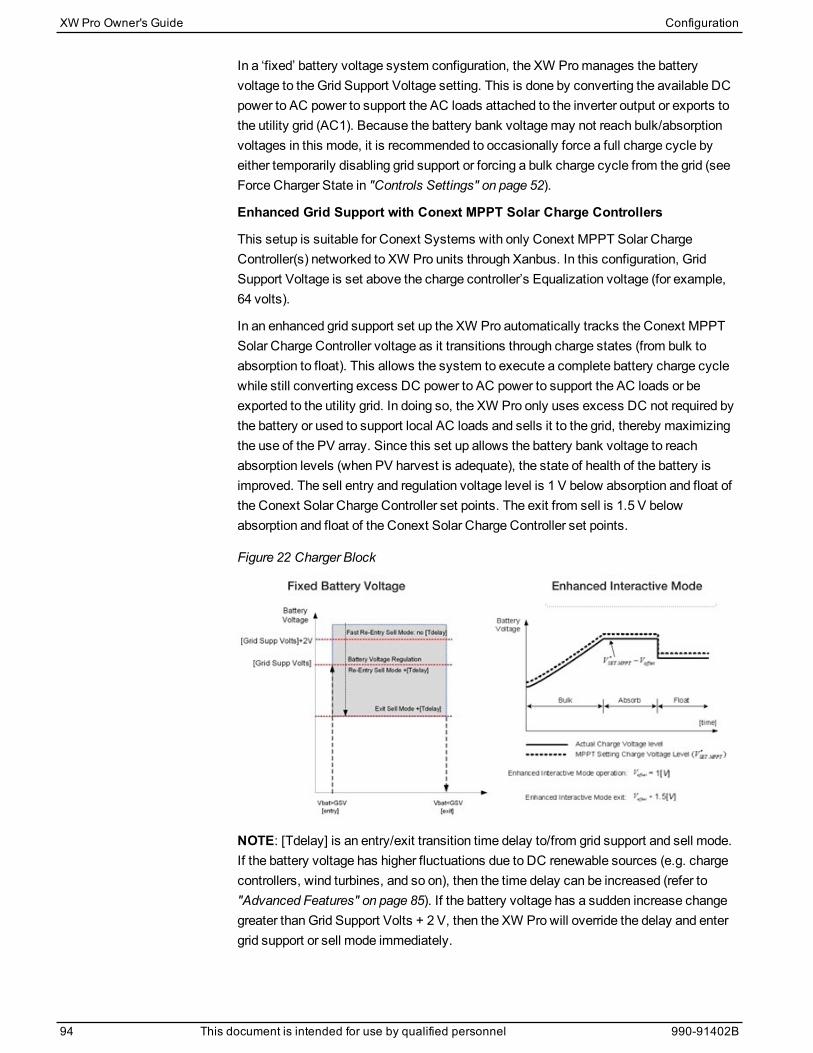
In a ‘fixed’ battery voltage system configuration, the XW Promanages the batteryvoltage to the Grid Support Voltage setting. This is done by converting the available DCpower to AC power to support the AC loads attached to the inverter output or exports tothe utility grid (AC1). Because the battery bank voltagemay not reach bulk/absorptionvoltages in this mode, it is recommended to occasionally force a full charge cycle byeither temporarily disabling grid support or forcing a bulk charge cycle from the grid (seeForce Charger State in "Controls Settings" on page 52).
Enhanced Grid Support with Conext MPPT Solar Charge Controllers
This setup is suitable for Conext Systems with only Conext MPPT Solar ChargeController(s) networked to XW Pro units through Xanbus. In this configuration, GridSupport Voltage is set above the charge controller’s Equalization voltage (for example,64 volts).
In an enhanced grid support set up the XW Pro automatically tracks the Conext MPPTSolar Charge Controller voltage as it transitions through charge states (from bulk toabsorption to float). This allows the system to execute a complete battery charge cyclewhile still converting excess DC power to AC power to support the AC loads or beexported to the utility grid. In doing so, the XW Pro only uses excess DC not required bythe battery or used to support local AC loads and sells it to the grid, thereby maximizingthe use of the PV array. Since this set up allows the battery bank voltage to reachabsorption levels (when PV harvest is adequate), the state of health of the battery isimproved. The sell entry and regulation voltage level is 1 V below absorption and float ofthe Conext Solar Charge Controller set points. The exit from sell is 1.5 V belowabsorption and float of the Conext Solar Charge Controller set points.
Figure 22 Charger Block
NOTE: [Tdelay] is an entry/exit transition time delay to/from grid support and sell mode.If the battery voltage has higher fluctuations due to DC renewable sources (e.g. chargecontrollers, wind turbines, and so on), then the time delay can be increased (refer to"Advanced Features" on page 85). If the battery voltage has a sudden increase changegreater thanGrid Support Volts + 2 V, then the XW Pro will override the delay and entergrid support or sell mode immediately.
XW Pro Owner's Guide Configuration
94 This document is intended for use by qualified personnel 990-91402B

Charger BlockThe charger block feature halts charging on AC1 (Grid) for a period of time each day. Thisperiod of time is defined by the Charge Block Start and Charge Block Stop settings. Inareas where the utility charges variable rates for electricity, it is preferable to use utilitypower for charging only during non-peak hours. Charger block can prevent utility powerfrom being used for battery charging during peak billing periods.
During the time period set between Charge Block Start and Charge Block Stop, AC1(Grid) input continues to be passed through to the loads. Inverter operation remainsunaffected during the charger block period.
During the charger block period, no charging on AC1 occurs even if the batteriesdischarge below Recharge Voltage/SoC setting. However, a generator connected toAC2 (in the absence of utility/AC1 power) or a Conext MPPT solar charge controller maycharge batteries during the charger block period. AC priority must be set to AC2 to chargebatteries with a generator connected to AC2 during the charger block period.
If the charger is operating (that is, in float, absorption, bulk, or equalize stage) at theCharge Block Start time, charging on AC1 stops immediately and the charger enters anidle state identical to no float (see "Charger Settings" on page 57). When the chargerblock period is over, the charger does not resume the charge stage that was interrupted.Instead, if the batteries are above the Recharge Voltage/SoC setting, the chargerremains idle.
If the battery voltage discharges below the Recharge Voltage/SoC setting during thecharger block period, the XW Pro begins a new charge cycle with the bulk stage after thecharger block period has expired (at the Charge Block Stop time).
For example, charger block is set to start at 5:00 PM and end at 8:00 PM. If the XW Prois charging from AC1, charging stops at 5:00. When charger block ends at 8:00, the XWPro does not automatically resume charging. The unit first measures the battery voltage.
n If the voltage is below the Recharge Voltage setting, or if the state of charge is belowRecharge SoC, then the XW Pro starts a new charge cycle from bulk.
n If the voltage is above the Recharge Voltage setting, or if the state of charge is aboveRecharge SoC, then the XW Pro remains idle and continues passing through AC tothe loads.
The XW Pro also keeps measuring the battery voltage as before to determine whether tostart a new charge cycle.
Peak Load Shaving (PLS)Many utilities impose a surcharge on their customers based on the peak load used by afacility. To reduce utility peak demand charges, the inverter can be configured (using theLoad Shave Amps setting) to help limit themaximum draw the AC loads place on theutility. The inverter can be programmed to provide power above a specified level to avoidthe surcharge. When the utility current draw reaches themaximum level, the inverterassists by sourcing power from the batteries to the loads.
Configuration XW Pro Owner's Guide
990-91402B This document is intended for use by qualified personnel 95
For PLS to be effective, all loads must be connected to the inverter. For large loads,multiple (or stacked) inverters may be required.
To help the batteries supplement the power requirements of the connected load, anadditional source of power (solar, wind, or hydroelectric) is recommended.
The default PLS setting for Time in Float is zero. In this case, PLS is only entered/exitedas programmedwithin the time window.
When the Time in Float is different than zero, PLS shall start only if the battery amperageremained at the specified level for the configured time.
Example Settings
Load Shave=Enabled, Load Shave Amps=10 A,
LoadShaveStart=6:00pm, LoadShaveStop=9:00pm, Time in Float=60
min, Peak Load Shave Delay = Enabled.
With these example settings, the XW Pro would enter PLS within the configured windowof time only if the battery was charged fromMPPT in Float (including Absorption) for 2hours.
NOTE: When actively operating, the XW Pro compensates for active power as areference for controlling the total current as specified in the Load Shave Amps setting.However, there is also reactive power that is not compensated for by the XW Pro. Forexample, if Load Shave Amps is set to 10A, the inverter will only start drawing powerfrom the batteries at a current level which wouldmeasure approximately 11A which is 1Ahigher than the Load Shave Amps value tomeet the demand of the loads.
Time-of-Use MeteringUtilities use time-of-usemetering to determine utility charges during peak usage hoursand to impose a surcharge. The XW Pro can be configured (using the Load Shave Start,Load Shave Stop and Charger Block settings) to overcome these peak charges by usingutility power to charge the battery bank during the inexpensive energy hours andconsuming the battery energy during expensive energy hours.
For example, if Charger Block is set between 9:00 AM and 10:00 PM and Load Shave isset between 6:00 PM and 9:00 PM, charging on AC1 stops at 9:00 AM and continues topass through utility AC to the loads. If charging is required during the charger blockperiod, and AC Priority is set to AC2, the XW Pro can use any AC source connected toAC2. Loads will transfer to the AC source on AC2 as well.The inverter connects to theutility grid at 6:00 PM and supports loads using the batteries. The inverter continues torun until 9:00 PM. The XW Pro then stops supporting the utility grid and passes utility ACthrough to the loads. At 10:00 PM utility AC begins maintaining the batteries based on thebattery charger settings.
The above example allows an external renewable energy source to be utilized as aprimary charging source during a desired time window. The charger (using utility ACconnected to AC1) can then be used to supplement the battery charging when the utilityrates are low.
XW Pro Owner's Guide Configuration
96 This document is intended for use by qualified personnel 990-91402B
When using the system for time-of-usemetering, the system should be designed with abattery capacity large enough to support loads during the entire peak rate period withoutreaching the Low Battery Cut Out or Low Battery Cut Out SoC setting.
NOTE: If the batteries reach the Low Battery Cut Out setting, the XW Pro automaticallyreconnects to the utility grid to maintain the connected load.
Self-ConsumptionPLS can also be used with time-of-usemetering to support self-consumption. In the self-consumptionmode of operation, the XW Pro delays Peak Load Shavemode by a fixedtime of 2 hours. This is done by allowing a priority for theMPPT solar charge controller tocharge the battery bank.
This configuration can be selected under the XW Promenu by setting Peak LoadShaving Delay under Advanced Features to Enabled. The default setting for is Disabled.
Configuration XW Pro Owner's Guide
990-91402B This document is intended for use by qualified personnel 97
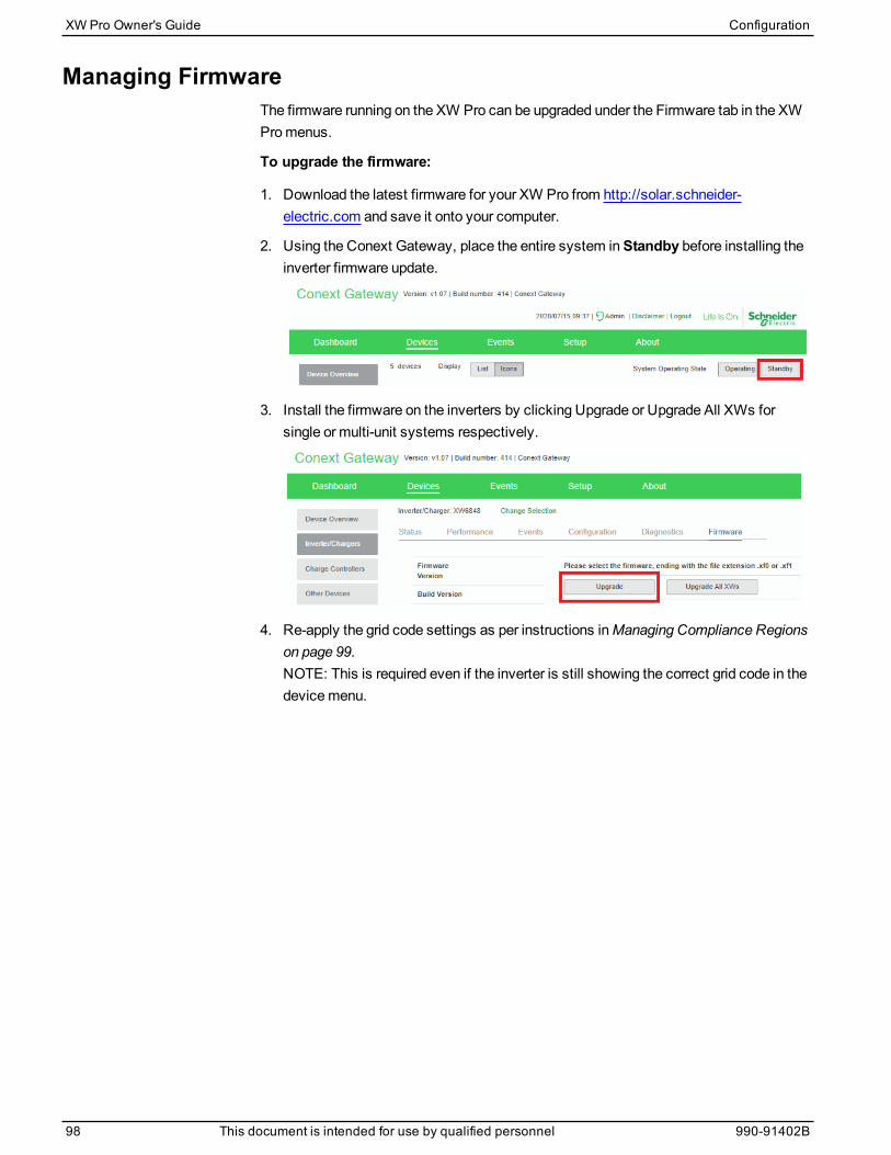
Managing FirmwareThe firmware running on the XW Pro can be upgraded under the Firmware tab in the XWPromenus.
To upgrade the firmware:
1. Download the latest firmware for your XW Pro from http://solar.schneider-electric.com and save it onto your computer.
2. Using the Conext Gateway, place the entire system inStandby before installing theinverter firmware update.
3. Install the firmware on the inverters by clicking Upgrade or Upgrade All XWs forsingle or multi-unit systems respectively.
4. Re-apply the grid code settings as per instructions inManaging Compliance Regionson page 99.NOTE: This is required even if the inverter is still showing the correct grid code in thedevicemenu.
XW Pro Owner's Guide Configuration
98 This document is intended for use by qualified personnel 990-91402B
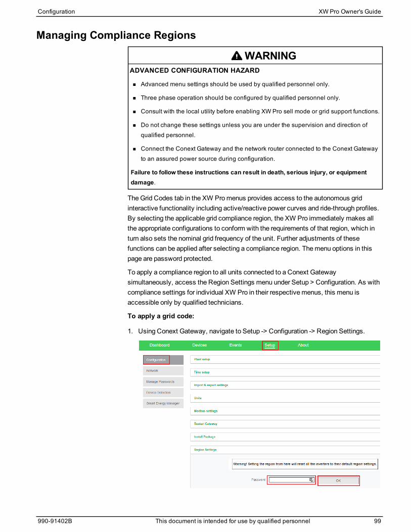
Managing Compliance Regions
WARNINGADVANCED CONFIGURATION HAZARD
n Advanced menu settings should be used by qualified personnel only.
n Three phase operation should be configured by qualified personnel only.
n Consult with the local utility before enabling XW Pro sell mode or grid support functions.
n Do not change these settings unless you are under the supervision and direction ofqualified personnel.
n Connect the Conext Gateway and the network router connected to the Conext Gatewayto an assured power source during configuration.
Failure to follow these instructions can result in death, serious injury, or equipmentdamage.
TheGrid Codes tab in the XW Promenus provides access to the autonomous gridinteractive functionality including active/reactive power curves and ride-through profiles.By selecting the applicable grid compliance region, the XW Pro immediately makes allthe appropriate configurations to conform with the requirements of that region, which inturn also sets the nominal grid frequency of the unit. Further adjustments of thesefunctions can be applied after selecting a compliance region. Themenu options in thispage are password protected.
To apply a compliance region to all units connected to a Conext Gatewaysimultaneously, access the Region Settings menu under Setup > Configuration. As withcompliance settings for individual XW Pro in their respectivemenus, this menu isaccessible only by qualified technicians.
To apply a grid code:
1. Using Conext Gateway, navigate to Setup -> Configuration -> Region Settings.
Configuration XW Pro Owner's Guide
990-91402B This document is intended for use by qualified personnel 99
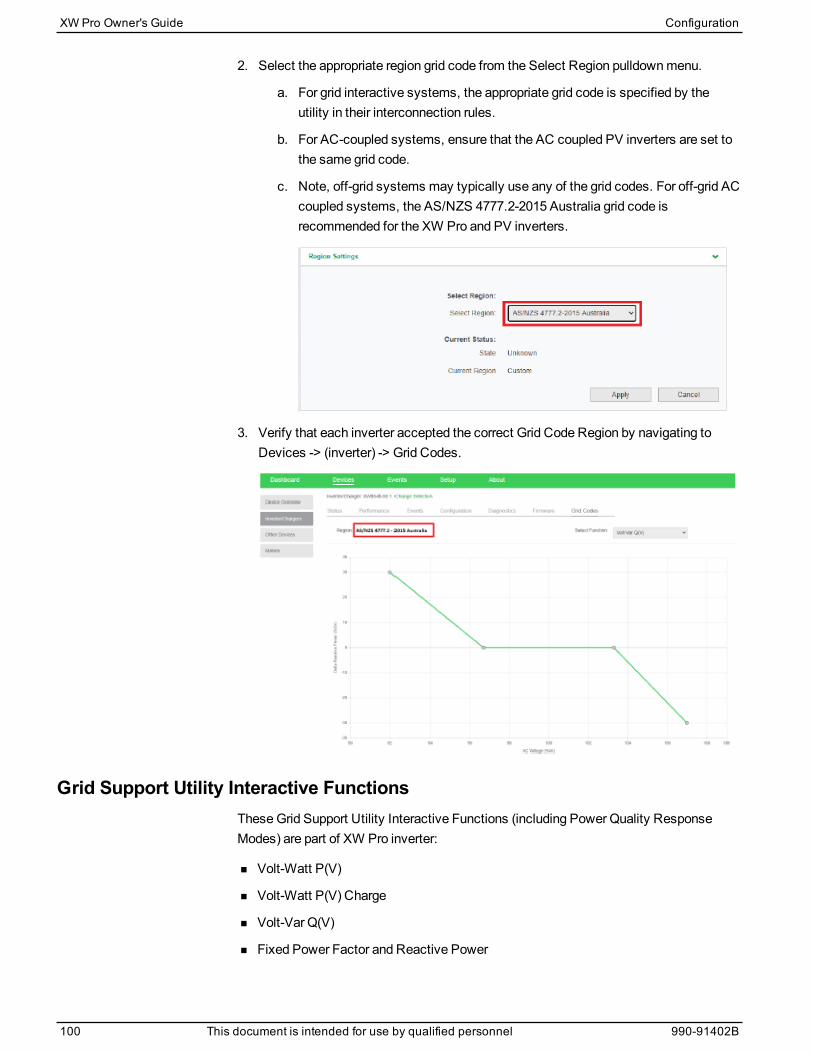
2. Select the appropriate region grid code from the Select Region pulldownmenu.
a. For grid interactive systems, the appropriate grid code is specified by theutility in their interconnection rules.
b. For AC-coupled systems, ensure that the AC coupled PV inverters are set tothe same grid code.
c. Note, off-grid systems may typically use any of the grid codes. For off-grid ACcoupled systems, the AS/NZS 4777.2-2015 Australia grid code isrecommended for the XW Pro and PV inverters.
3. Verify that each inverter accepted the correct Grid Code Region by navigating toDevices -> (inverter) -> Grid Codes.
Grid Support Utility Interactive FunctionsTheseGrid Support Utility Interactive Functions (including Power Quality ResponseModes) are part of XW Pro inverter:
n Volt-Watt P(V)
n Volt-Watt P(V) Charge
n Volt-Var Q(V)
n Fixed Power Factor and Reactive Power
XW Pro Owner's Guide Configuration
100 This document is intended for use by qualified personnel 990-91402B
n RampRates
n Frequency-Watt P(f) Pre-Disturbance
n Frequency-Watt P(f) Pre-Disturbance Charge
Configuration XW Pro Owner's Guide
990-91402B This document is intended for use by qualified personnel 101

AS/NZS 4777.2-2015 AustraliaP(V) Volt-Watt Function
When the XW Pro is inGrid Supportmode and P(V) function is enabled:
n XW Pro dynamically curtails active power injected into the utility grid in response tovoltage fluctuations.
n By adjusting active power in response to grid voltage fluctuations, XW Procontributes to grid stabilization towards the nominal value.
P(V) function is enabled by default.
This mode can be checked/configured via Conext Gateway GUI by navigating toDevices -> XW Pro -> Grid Codes (password-protected).
Figure 23 Default settings of Volt-Watt function
If needed, customer can change parameters of the functions and click Apply to save thenews settings. The following parameters are supported:
n Point 1 is the starting point of active power curtailment.
n Point 2 is the finish point of active power curtailment.
l Y is expressed as % of rated active power of the inverter.
l X is expressed as % of nominal AC voltage of the inverter.
XW Pro Owner's Guide Configuration
102 This document is intended for use by qualified personnel 990-91402B
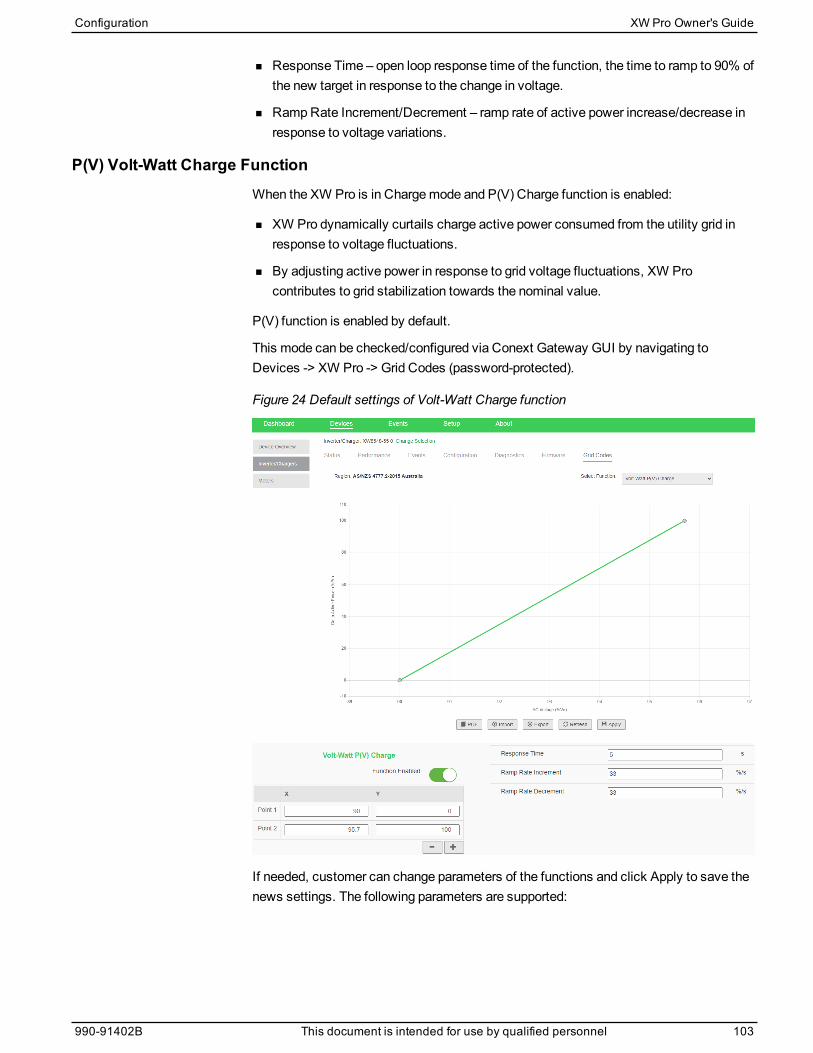
n Response Time – open loop response time of the function, the time to ramp to 90% ofthe new target in response to the change in voltage.
n RampRate Increment/Decrement – ramp rate of active power increase/decrease inresponse to voltage variations.
P(V) Volt-Watt Charge FunctionWhen the XW Pro is in Chargemode and P(V) Charge function is enabled:
n XW Pro dynamically curtails charge active power consumed from the utility grid inresponse to voltage fluctuations.
n By adjusting active power in response to grid voltage fluctuations, XW Procontributes to grid stabilization towards the nominal value.
P(V) function is enabled by default.
This mode can be checked/configured via Conext Gateway GUI by navigating toDevices -> XW Pro -> Grid Codes (password-protected).
Figure 24 Default settings of Volt-Watt Charge function
If needed, customer can change parameters of the functions and click Apply to save thenews settings. The following parameters are supported:
Configuration XW Pro Owner's Guide
990-91402B This document is intended for use by qualified personnel 103

n Point 1 is the finish point of active power curtailment.
n Point 2 is the starting point of active power curtailment.
l Y is expressed as % of rated charge active power of the inverter.
l X is expressed as % of nominal AC voltage of the inverter.
n Response Time – open loop response time of the function, the time to ramp to 90% ofthe new target in response to the change in voltage.
n RampRate Increment/Decrement – ramp rate of active power increase/decrease inresponse to voltage variations.
Q(V) Volt-Var FunctionWhen the XW Pro is inGrid Support mode andQ(V) function is enabled:
n XW Pro dynamically changes reactive power injected into the utility grid in responseto voltage variations.
n By adjusting reactive power in response to grid voltage fluctuations, XW Procontributes to grid stabilization towards the nominal value.
Q(V) function is disabled by default.
Q(V) Volt-Var function has priority over generated active power. XW Promay need toreduce produced active power tomeet the reactive power demand.
This mode can be checked/configured via Conext Gateway GUI by navigating toDevices -> XW Pro -> Grid Codes (password-protected).
Figure 25 Default settings of Volt-Var function
XW Pro Owner's Guide Configuration
104 This document is intended for use by qualified personnel 990-91402B
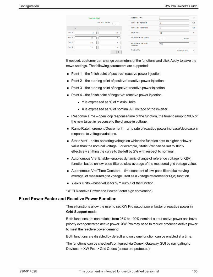
If needed, customer can change parameters of the functions and click Apply to save thenews settings. The following parameters are supported:
n Point 1 – the finish point of positive* reactive power injection.
n Point 2 – the starting point of positive* reactive power injection.
n Point 3 – the starting point of negative* reactive power injection.
n Point 4 – the finish point of negative* reactive power injection.
l Y is expressed as % of Y Axis Units.
l X is expressed as % of nominal AC voltage of the inverter.
n Response Time – open loop response time of the function, the time to ramp to 90% ofthe new target in response to the change in voltage.
n RampRate Increment/Decrement – ramp rate of reactive power increase/decrease inresponse to voltage variations.
n Static Vref – shifts operating voltage on which the function acts to higher or lowervalue than the nominal voltage. For example, Static Vref can be set to 102%effectively shifting the curve to the left by 2% with respect to nominal.
n Autonomous Vref Enable– enables dynamic change of reference voltage for Q(V)function based on low-pass-filtered slow average of themeasured grid voltage value.
n Autonomous Vref TimeConstant – time constant of low-pass filter (akamovingaverage) of measured grid voltage used as a voltage reference for Q(V) function.
n Y-axis Units – base value for% Y output of the function.
* (EEI Reactive Power and Power Factor sign convention)
Fixed Power Factor and Reactive Power FunctionThese functions allow the user to set XW Pro output power factor or reactive power inGrid Supportmode.
Both functions are controllable from 25% to 100% nominal output active power and havepriority over generated active power. XW Promay need to reduce produced active powertomeet the reactive power demand.
Both functions are disabled by default and only one function can be enabled at a time.
The functions can be checked/configured via Conext Gateway GUI by navigating toDevices -> XW Pro -> Grid Codes (password-protected).
Configuration XW Pro Owner's Guide
990-91402B This document is intended for use by qualified personnel 105
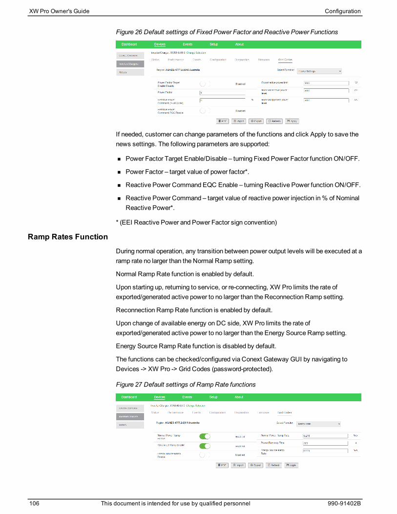
Figure 26 Default settings of Fixed Power Factor and Reactive Power Functions
If needed, customer can change parameters of the functions and click Apply to save thenews settings. The following parameters are supported:
n Power Factor Target Enable/Disable – turning Fixed Power Factor function ON/OFF.
n Power Factor – target value of power factor*.
n Reactive Power Command EQC Enable – turning Reactive Power function ON/OFF.
n Reactive Power Command – target value of reactive power injection in% of NominalReactive Power*.
* (EEI Reactive Power and Power Factor sign convention)
Ramp Rates FunctionDuring normal operation, any transition between power output levels will be executed at aramp rate no larger than the Normal Ramp setting.
Normal RampRate function is enabled by default.
Upon starting up, returning to service, or re-connecting, XW Pro limits the rate ofexported/generated active power to no larger than the Reconnection Ramp setting.
Reconnection RampRate function is enabled by default.
Upon change of available energy on DC side, XW Pro limits the rate ofexported/generated active power to no larger than the Energy Source Ramp setting.
Energy Source RampRate function is disabled by default.
The functions can be checked/configured via Conext Gateway GUI by navigating toDevices -> XW Pro -> Grid Codes (password-protected).
Figure 27 Default settings of RampRate functions
XW Pro Owner's Guide Configuration
106 This document is intended for use by qualified personnel 990-91402B
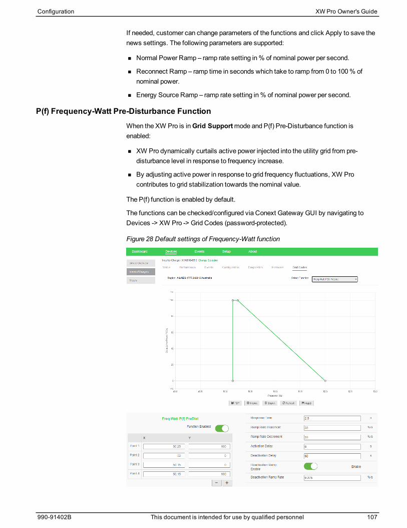
If needed, customer can change parameters of the functions and click Apply to save thenews settings. The following parameters are supported:
n Normal Power Ramp – ramp rate setting in% of nominal power per second.
n Reconnect Ramp – ramp time in seconds which take to ramp from 0 to 100% ofnominal power.
n Energy Source Ramp – ramp rate setting in% of nominal power per second.
P(f) Frequency-Watt Pre-Disturbance FunctionWhen the XW Pro is inGrid Supportmode and P(f) Pre-Disturbance function isenabled:
n XW Pro dynamically curtails active power injected into the utility grid from pre-disturbance level in response to frequency increase.
n By adjusting active power in response to grid frequency fluctuations, XW Procontributes to grid stabilization towards the nominal value.
The P(f) function is enabled by default.
The functions can be checked/configured via Conext Gateway GUI by navigating toDevices -> XW Pro -> Grid Codes (password-protected).
Figure 28 Default settings of Frequency-Watt function
Configuration XW Pro Owner's Guide
990-91402B This document is intended for use by qualified personnel 107
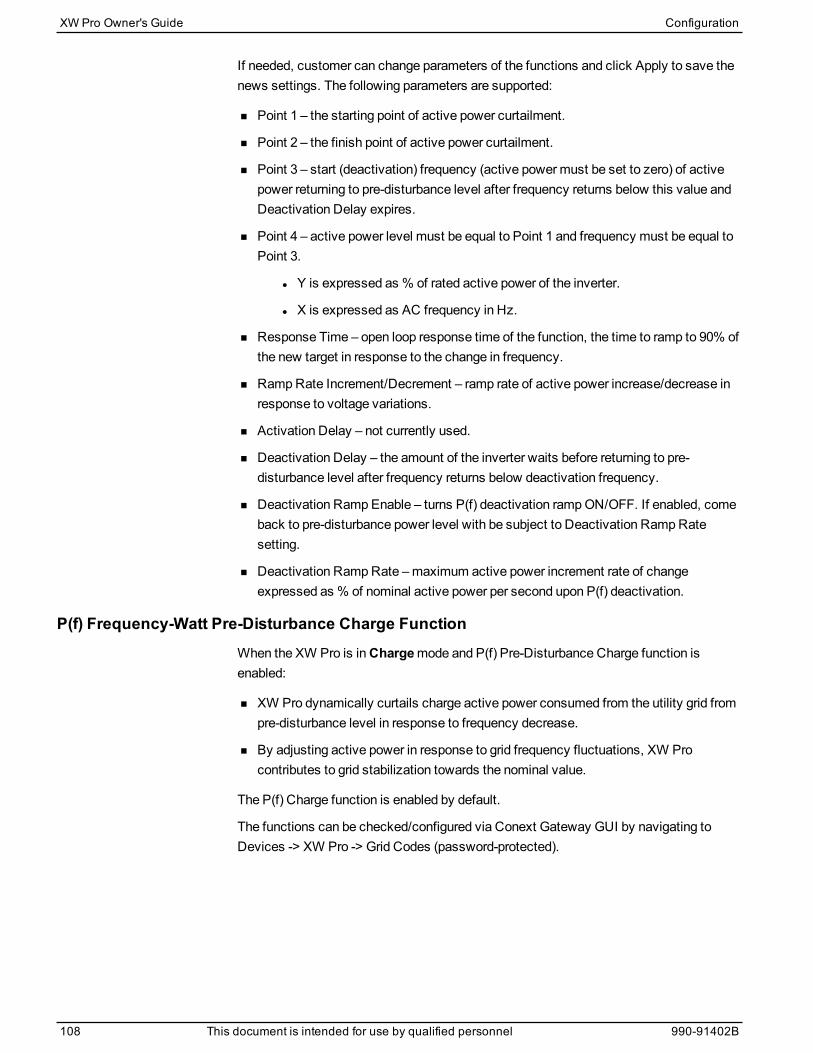
If needed, customer can change parameters of the functions and click Apply to save thenews settings. The following parameters are supported:
n Point 1 – the starting point of active power curtailment.
n Point 2 – the finish point of active power curtailment.
n Point 3 – start (deactivation) frequency (active powermust be set to zero) of activepower returning to pre-disturbance level after frequency returns below this value andDeactivation Delay expires.
n Point 4 – active power level must be equal to Point 1 and frequency must be equal toPoint 3.
l Y is expressed as % of rated active power of the inverter.
l X is expressed as AC frequency in Hz.
n Response Time – open loop response time of the function, the time to ramp to 90% ofthe new target in response to the change in frequency.
n RampRate Increment/Decrement – ramp rate of active power increase/decrease inresponse to voltage variations.
n Activation Delay – not currently used.
n Deactivation Delay – the amount of the inverter waits before returning to pre-disturbance level after frequency returns below deactivation frequency.
n Deactivation Ramp Enable – turns P(f) deactivation rampON/OFF. If enabled, comeback to pre-disturbance power level with be subject to Deactivation RampRatesetting.
n Deactivation RampRate –maximum active power increment rate of changeexpressed as % of nominal active power per second upon P(f) deactivation.
P(f) Frequency-Watt Pre-Disturbance Charge FunctionWhen the XW Pro is inChargemode and P(f) Pre-Disturbance Charge function isenabled:
n XW Pro dynamically curtails charge active power consumed from the utility grid frompre-disturbance level in response to frequency decrease.
n By adjusting active power in response to grid frequency fluctuations, XW Procontributes to grid stabilization towards the nominal value.
The P(f) Charge function is enabled by default.
The functions can be checked/configured via Conext Gateway GUI by navigating toDevices -> XW Pro -> Grid Codes (password-protected).
XW Pro Owner's Guide Configuration
108 This document is intended for use by qualified personnel 990-91402B
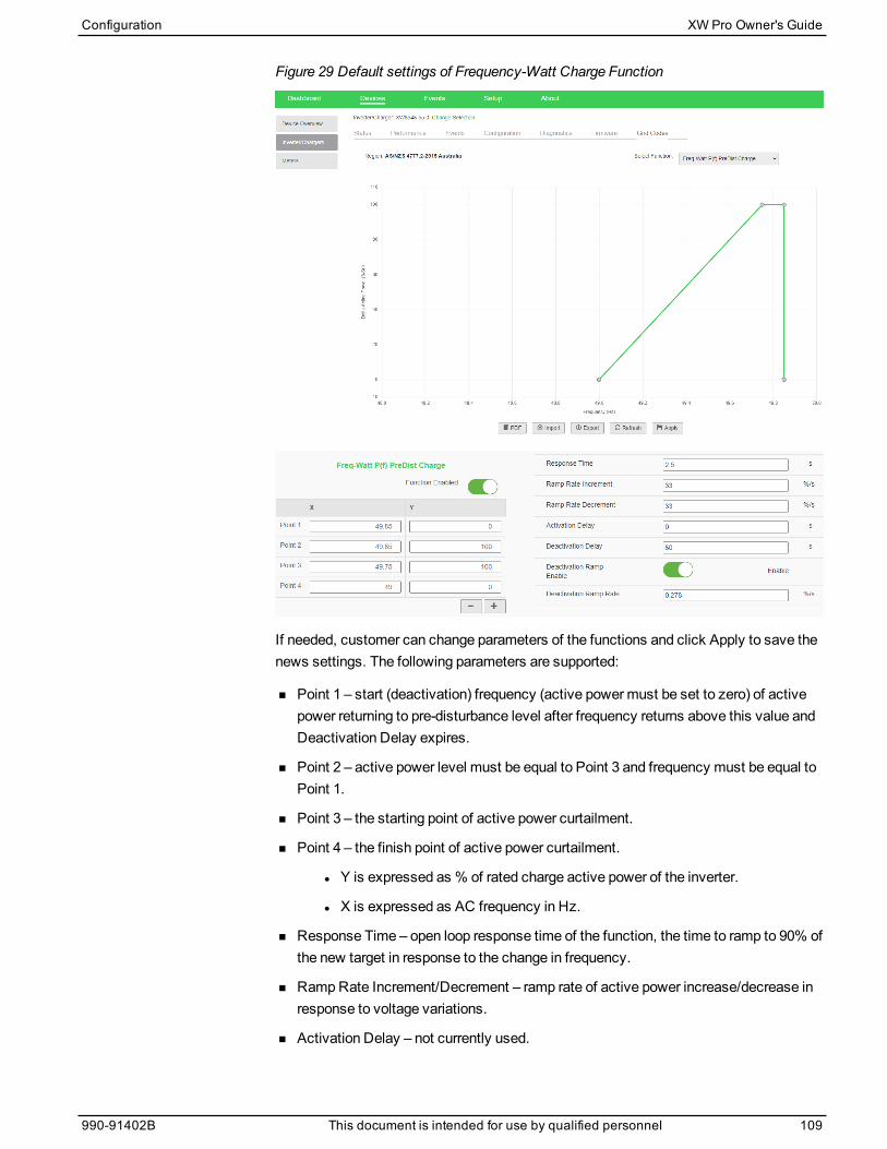
Figure 29 Default settings of Frequency-Watt Charge Function
If needed, customer can change parameters of the functions and click Apply to save thenews settings. The following parameters are supported:
n Point 1 – start (deactivation) frequency (active powermust be set to zero) of activepower returning to pre-disturbance level after frequency returns above this value andDeactivation Delay expires.
n Point 2 – active power level must be equal to Point 3 and frequency must be equal toPoint 1.
n Point 3 – the starting point of active power curtailment.
n Point 4 – the finish point of active power curtailment.
l Y is expressed as % of rated charge active power of the inverter.
l X is expressed as AC frequency in Hz.
n Response Time – open loop response time of the function, the time to ramp to 90% ofthe new target in response to the change in frequency.
n RampRate Increment/Decrement – ramp rate of active power increase/decrease inresponse to voltage variations.
n Activation Delay – not currently used.
Configuration XW Pro Owner's Guide
990-91402B This document is intended for use by qualified personnel 109

n Deactivation Delay – the amount of the inverter waits before returning to pre-disturbance level after frequency returns above deactivation frequency.
n Deactivation Ramp Enable – turns P(f) deactivation rampON/OFF. If enabled, comeback to pre-disturbance power level will be subject to Deactivation RampRatesetting.
n Deactivation RampRate –maximum active power increment rate of changeexpressed as % of nominal charge active power per second upon P(f) deactivation.
XW Pro Owner's Guide Configuration
110 This document is intended for use by qualified personnel 990-91402B
Resetting the XW Pro to Default Settings
WARNINGADVANCED CONFIGURATION HAZARD
n Advanced menu settings should be used by qualified personnel only.
n Three phase operation should be configured by qualified personnel only.
n Consult with the local utility before enabling XW Pro sell mode or grid support functions.
n Do not change these settings unless you are under the supervision and direction ofqualified personnel.
n Connect the Conext Gateway and the network router connected to the Conext Gatewayto an assured power source during configuration.
Failure to follow these instructions can result in death, serious injury, or equipmentdamage.
The Reset to Factory command returns the XW Pro to factory default settings. Afterusing the Reset to Factory command, the XW Pro is no longer configured for the powersystem.
NOTICERESTORING DEFAULTS
Do not restore defaults while the XW Pro is operating. De-energize the power system anddisconnect the XW Pro AC input before restoring defaults. Reconfigure the XW Pro beforereconnecting the AC input and re-energizing the power system.
Failure to follow these instructions can result in equipment damage.
To restore the XW Pro default settings, on the Controls Setupmenu in the Advancedview, select Reset to Factory for the Reset control.
Configuration XW Pro Owner's Guide
990-91402B This document is intended for use by qualified personnel 111

Troubleshooting5
General Troubleshooting Guidelines 114Inverter Applications 115Resistive Loads 115Motor Loads 115Problem Loads 115
Inverter Troubleshooting 117Battery Charger Troubleshooting 120Faults and Warnings 122WarningMessages 122Fault Messages 125
What's in This Chapter?
General Troubleshooting GuidelinesThis section will help you narrow down the source of any problem youmay encounter.Please read the following troubleshooting steps:
1. Check for aWarning or Fault message on the Conext Gateway web application or aFault code on the inverter information panel. If a message is displayed, record itimmediately.
2. As soon as possible, create a detailed record of the conditions at the time the problemoccurred. These details should include, but not be limited to, the following:
n Loads the XW Pro was running or attempting to run.
n Battery condition at the time of failure (for example battery voltage or temperature) ifknown.
n Recent sequence of events (for example, charging had just finished, utility grid hadfailed but the inverter did not start up).
n Any known unusual AC input factors such as low voltage or unstable generatoroutput.
n Extreme conditions whichmay have existed at the time (for example, temperature ormoisture).
3. Attempt the solution corresponding to theWarning or Fault message in Faults andWarnings on page 122.
4. If the Event LED is not lit up on the front of the inverter information panel or theConext Gateway web application shows no event, check the following list to makesure that the present state of the installation allows proper operation of the unit. Seealso "Inverter Troubleshooting" on page 117 or "Battery Charger Troubleshooting" onpage 120.
n Is the XW Pro located in a clean, dry, adequately ventilated area?
n Have the AC input breakers opened? If so, your passthrough loadmay haveexceeded the rating of one or more of the input breakers.
n Are the battery cables adequately sized and short enough? See theXW ProInstallation Guide for more information.
n Is the battery in good condition and are all DC connections tight?
n Are the AC input and output connections and wiring in good condition?
n Are the configuration settings correct for your particular installation?
n Are the display panel and the communications cable properly connected andundamaged?
n Are the battery temperature sensor and its cable properly connected and undamaged?
5. Contact Customer Service for further assistance. Please be prepared to describedetails of your system installation and provide themodel and serial number of theunit. See beginning of document for contact information.
XW Pro Owner's Guide Troubleshooting
114 This document is intended for use by qualified personnel 990-91402B
Inverter ApplicationsThe XW Pro performs differently depending on the AC loads connected to it. If you arehaving problems with any of your loads, read this section.
Resistive LoadsResistive loads are the easiest andmost efficient to drive. Voltage and current are inphase, whichmeans they are in step with one another. Resistive loads generate heat inorder to accomplish their tasks. Toasters, coffee pots, and incandescent lights aretypical resistive loads. It is usually impractical to run larger resistive loads—such aselectric stoves and water heaters—from an inverter due to their high currentrequirements. Even though the inverter may be able to accommodate the load, the size ofbattery bank will limit inverter run time.
Motor LoadsInductionmotors (AC motors without brushes) require up to six times their runningcurrent on startup. Themost demanding are those that start under load (for example,compressors and pumps). Of the capacitor start motors (typical in tools such as drillpresses and band saws), the largest you can expect to run is 1 horsepower. Universalmotors are generally easier to start. Check that the Locked Rotor Amps (LRA) rating ofthemotor load does not exceed themaximum surge current rating of the inverter. Sincemotor characteristics vary, only testing will determine whether a specific load can bestarted and how long it can be run.
If a motor fails to start within a few seconds or loses power after running for a time, itshould be turned off. When the inverter attempts to start a load that is greater than it canhandle, the inverter may shut down from an AC overload fault.
Problem Loads
Very Small LoadsIf the power consumed by a device is less than the threshold of the searchmodecircuitry, and searchmode is enabled, the inverter will not run. Most likely the solutionwill be to disable Searchmode or lower the sense threshold (see "Inverter Settings" onpage 53).
Fluorescent Lights and Power SuppliesSome devices cannot be detected when scanned by searchmode circuitry. Smallfluorescent lights are themost common example. Some computers and sophisticatedelectronics have power supplies that do not present a load until line voltage is available.When this occurs, each unit waits for the other to begin. To drive these loads, either asmall companion load like a light bulb rated for more than the SearchWatts settingmustbe used to bring the inverter out of searchmode, or the inverter may be programmed toremain on by disabling searchmode (see "Inverter Settings" on page 53).
Troubleshooting XW Pro Owner's Guide
990-91402B This document is intended for use by qualified personnel 115
ClocksYoumay notice that your clocks are not accurate. Some of the clocks on your appliancesmay reset when the XW Pro is in search mode. Disabling searchmode will resolve thisissue (see "Inverter Settings" on page 53).
SearchingWhen the inverter is in searchmode, it may fail to start some loads even though the ratedwattage on the load is more than theMaximum SearchWatts setting. Disable search orapply an additional load (companion load) to make the inverter exit searchmode.
XW Pro Owner's Guide Troubleshooting
116 This document is intended for use by qualified personnel 990-91402B
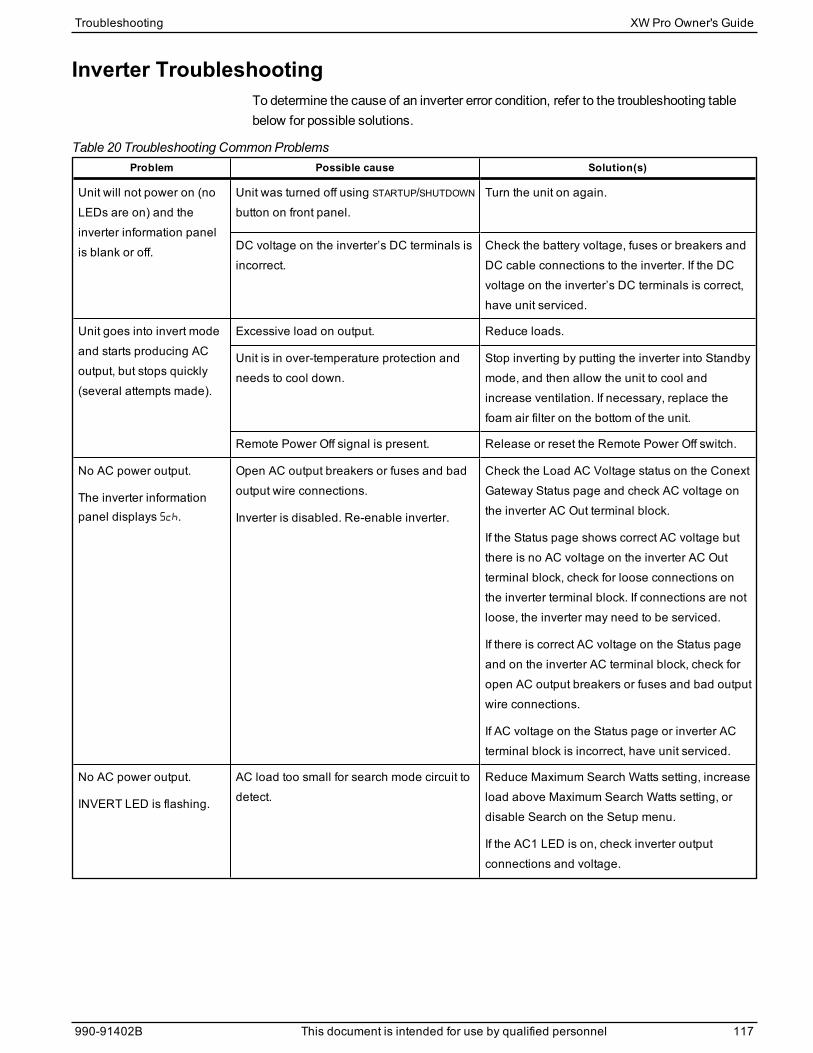
Inverter TroubleshootingTo determine the cause of an inverter error condition, refer to the troubleshooting tablebelow for possible solutions.
Problem Possible cause Solution(s)
Unit will not power on (noLEDs are on) and theinverter information panelis blank or off.
Unit was turned off using STARTUP/SHUTDOWN
button on front panel.Turn the unit on again.
DC voltage on the inverter’s DC terminals isincorrect.
Check the battery voltage, fuses or breakers andDC cable connections to the inverter. If the DCvoltage on the inverter’s DC terminals is correct,have unit serviced.
Unit goes into invert modeand starts producing ACoutput, but stops quickly(several attempts made).
Excessive load on output. Reduce loads.
Unit is in over-temperature protection andneeds to cool down.
Stop inverting by putting the inverter into Standbymode, and then allow the unit to cool andincrease ventilation. If necessary, replace thefoam air filter on the bottom of the unit.
Remote Power Off signal is present. Release or reset the Remote Power Off switch.
No AC power output.
The inverter informationpanel displays Sch.
Open AC output breakers or fuses and badoutput wire connections.
Inverter is disabled. Re-enable inverter.
Check the Load AC Voltage status on the ConextGateway Status page and check AC voltage onthe inverter AC Out terminal block.
If the Status page shows correct AC voltage butthere is no AC voltage on the inverter AC Outterminal block, check for loose connections onthe inverter terminal block. If connections are notloose, the inverter may need to be serviced.
If there is correct AC voltage on the Status pageand on the inverter AC terminal block, check foropen AC output breakers or fuses and bad outputwire connections.
If AC voltage on the Status page or inverter ACterminal block is incorrect, have unit serviced.
No AC power output.
INVERT LED is flashing.
AC load too small for search mode circuit todetect.
Reduce Maximum Search Watts setting, increaseload above Maximum Search Watts setting, ordisable Search on the Setup menu.
If the AC1 LED is on, check inverter outputconnections and voltage.
Table 20 Troubleshooting Common Problems
Troubleshooting XW Pro Owner's Guide
990-91402B This document is intended for use by qualified personnel 117
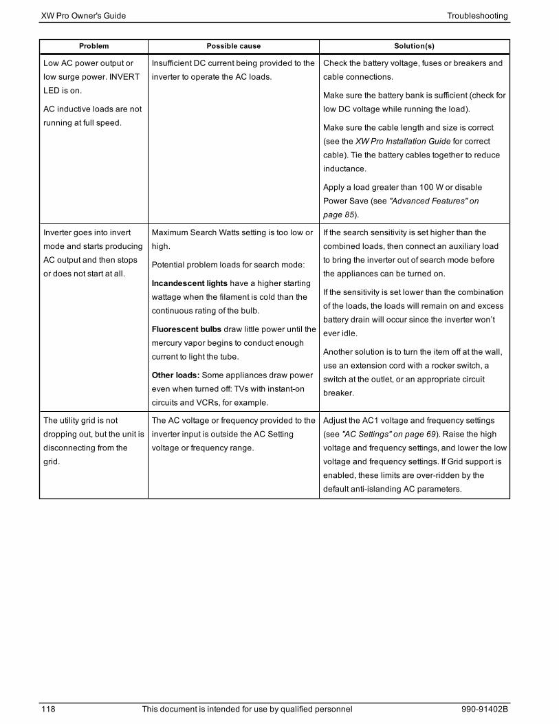
Problem Possible cause Solution(s)
Low AC power output orlow surge power. INVERTLED is on.
AC inductive loads are notrunning at full speed.
Insufficient DC current being provided to theinverter to operate the AC loads.
Check the battery voltage, fuses or breakers andcable connections.
Make sure the battery bank is sufficient (check forlow DC voltage while running the load).
Make sure the cable length and size is correct(see the XW Pro Installation Guide for correctcable). Tie the battery cables together to reduceinductance.
Apply a load greater than 100 W or disablePower Save (see "Advanced Features" onpage 85).
Inverter goes into invertmode and starts producingAC output and then stopsor does not start at all.
Maximum Search Watts setting is too low orhigh.
Potential problem loads for search mode:
Incandescent lights have a higher startingwattage when the filament is cold than thecontinuous rating of the bulb.
Fluorescent bulbs draw little power until themercury vapor begins to conduct enoughcurrent to light the tube.
Other loads: Some appliances draw powereven when turned off: TVs with instant-oncircuits and VCRs, for example.
If the search sensitivity is set higher than thecombined loads, then connect an auxiliary loadto bring the inverter out of search mode beforethe appliances can be turned on.
If the sensitivity is set lower than the combinationof the loads, the loads will remain on and excessbattery drain will occur since the inverter won’tever idle.
Another solution is to turn the item off at the wall,use an extension cord with a rocker switch, aswitch at the outlet, or an appropriate circuitbreaker.
The utility grid is notdropping out, but the unit isdisconnecting from thegrid.
The AC voltage or frequency provided to theinverter input is outside the AC Settingvoltage or frequency range.
Adjust the AC1 voltage and frequency settings(see "AC Settings" on page 69). Raise the highvoltage and frequency settings, and lower the lowvoltage and frequency settings. If Grid support isenabled, these limits are over-ridden by thedefault anti-islanding AC parameters.
XW Pro Owner's Guide Troubleshooting
118 This document is intended for use by qualified personnel 990-91402B
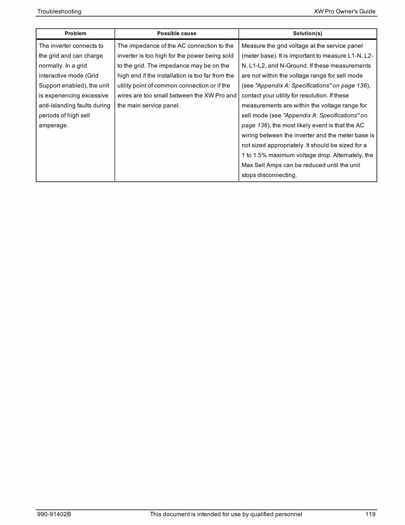
Problem Possible cause Solution(s)
The inverter connects tothe grid and can chargenormally. In a gridinteractive mode (GridSupport enabled), the unitis experiencing excessiveanti-islanding faults duringperiods of high sellamperage.
The impedance of the AC connection to theinverter is too high for the power being soldto the grid. The impedance may be on thehigh end if the installation is too far from theutility point of common connection or if thewires are too small between the XW Pro andthe main service panel.
Measure the grid voltage at the service panel(meter base). It is important to measure L1-N, L2-N, L1-L2, and N-Ground. If these measurementsare not within the voltage range for sell mode(see "Appendix A: Specifications" on page 136),contact your utility for resolution. If thesemeasurements are within the voltage range forsell mode (see "Appendix A: Specifications" onpage 136), the most likely event is that the ACwiring between the inverter and the meter base isnot sized appropriately. It should be sized for a1 to 1.5% maximum voltage drop. Alternately, theMax Sell Amps can be reduced until the unitstops disconnecting.
Troubleshooting XW Pro Owner's Guide
990-91402B This document is intended for use by qualified personnel 119
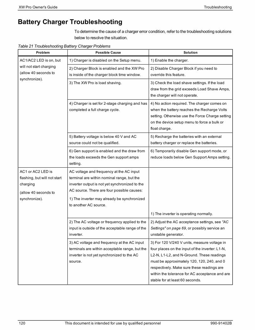
Battery Charger TroubleshootingTo determine the cause of a charger error condition, refer to the troubleshooting solutionsbelow to resolve the situation.
Problem Possible Cause Solution
AC1/AC2 LED is on, butwill not start charging(allow 40 seconds tosynchronize).
1) Charger is disabled on the Setup menu. 1) Enable the charger.
2) Charger Block is enabled and the XW Prois inside of the charger block time window.
2) Disable Charger Block if you need tooverride this feature.
3) The XW Pro is load shaving. 3) Check the load shave settings. If the loaddraw from the grid exceeds Load Shave Amps,the charger will not operate.
4) Charger is set for 2-stage charging and hascompleted a full charge cycle.
4) No action required. The charger comes onwhen the battery reaches the Recharge Voltssetting. Otherwise use the Force Charge settingon the device setup menu to force a bulk orfloat charge.
5) Battery voltage is below 40 V and ACsource could not be qualified.
5) Recharge the batteries with an externalbattery charger or replace the batteries.
6) Gen support is enabled and the draw fromthe loads exceeds the Gen support ampssetting.
6) Temporarily disable Gen support mode, orreduce loads below Gen Support Amps setting.
AC1 or AC2 LED isflashing, but will not startcharging
(allow 40 seconds tosynchronize).
AC voltage and frequency at the AC inputterminal are within nominal range, but theinverter output is not yet synchronized to theAC source. There are four possible causes:
1) The inverter may already be synchronizedto another AC source.
1) The inverter is operating normally.
2) The AC voltage or frequency applied to theinput is outside of the acceptable range of theinverter.
2) Adjust the AC acceptance settings, see "ACSettings" on page 69, or possibly service anunstable generator.
3) AC voltage and frequency at the AC inputterminals are within acceptable range, but theinverter is not yet synchronized to the ACsource.
3) For 120 V/240 V units, measure voltage infour places on the input of the inverter: L1-N,L2-N, L1-L2, and N-Ground. These readingsmust be approximately 120, 120, 240, and 0respectively. Make sure these readings arewithin the tolerance for AC acceptance and arestable for at least 60 seconds.
Table 21 Troubleshooting Battery Charger Problems
XW Pro Owner's Guide Troubleshooting
120 This document is intended for use by qualified personnel 990-91402B

Problem Possible Cause Solution
Charger amperage dropsoff before full charging hasfinished (no Event LED).
AC frequency at the AC input terminal may beout-of-tolerance (too high or low) or the ACvoltage may be outside the Hi AC Volt or LoAC Volt settings. AC input voltageapproaching the low disconnect level.
Check the settings on the AC Settings menu.Check for the correct AC voltage or frequencyat the AC input terminal. If the AC source is agenerator, adjust the AC voltage or frequencyaccordingly.
Increase the difference between the Hi AC Volt(AC1) and Lo AC Volt (AC1) settings to allowsynchronization.
The charge settings are incorrectly configuredfor your battery type.
Select the correct battery type or configure aCustom battery type.
Ambient temperature may be high, causingunit to overheat and ramp down the charging.
Cool the unit down or check for anythingpreventing air flow around the unit.
Battery bank has one or more bad cells orinadequate wiring.
Check tightness of battery connections andinterconnections. Replace battery.
Battery Management System on Lithium Ionbattery has interrupted charging.
Consult with battery manufacturer for batterycompatibility.
Charger stops before fullcharging (or equalization)has finished.
Event LED flashes and ACoutput drops momentarily.
Cold temperature around batteries withbattery temperature sensor (BTS) installedmay be causing unit to reach High Batt CutOut setting.
Disconnect BTS during charging or increaseHigh Batt Cut Out setting.
Charger output is low. Loose or corroded battery connections. Check and clean all connections.
Loose AC input connections. Check and tighten AC wiring connections.
Worn out batteries. Replace batteries.
Battery cables too small or too long. Refer to cable and battery recommendations inthe XW Pro Installation Guide.
Batteries being chargedabove the bulk/floatsettings.
If a BTS (Battery Temperature Sensor) isinstalled, it may be in a cold area or havefallen off the batteries.
Another DC charging source may be on thebatteries.
Inspect the BTS. Reduce Battery TemperatureCoefficient on Custom Battery Settings menu.
Battery bank size too small relative to chargeroutput.
Increase battery bank size or decrease maxcharge rate.
Note: To bring batteries that are cold to thecorrect state of charge may require charging ata higher voltage. This may be normal BTSoperation. Unplug the BTS and determine ifyour voltage returns to the bulk/float voltage.
Troubleshooting XW Pro Owner's Guide
990-91402B This document is intended for use by qualified personnel 121
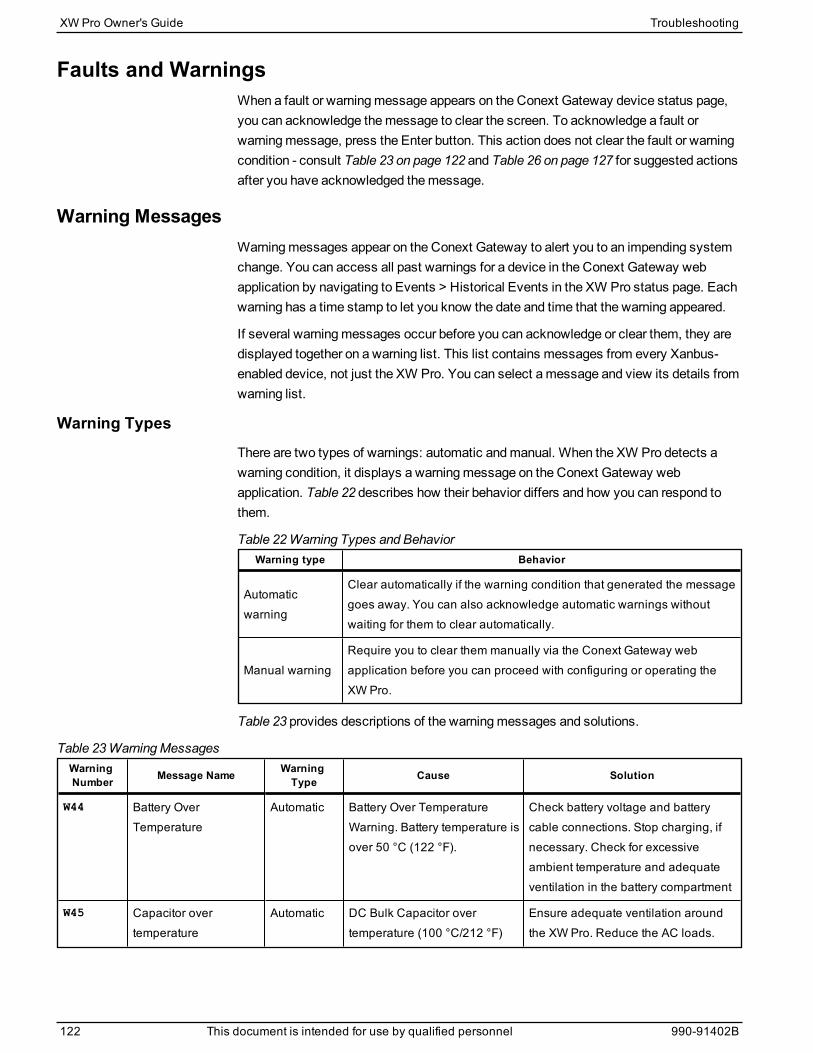
Faults and WarningsWhen a fault or warningmessage appears on the Conext Gateway device status page,you can acknowledge themessage to clear the screen. To acknowledge a fault orwarningmessage, press the Enter button. This action does not clear the fault or warningcondition - consult Table 23 on page 122 and Table 26 on page 127 for suggested actionsafter you have acknowledged themessage.
Warning MessagesWarningmessages appear on the Conext Gateway to alert you to an impending systemchange. You can access all past warnings for a device in the Conext Gateway webapplication by navigating to Events > Historical Events in the XW Pro status page. Eachwarning has a time stamp to let you know the date and time that the warning appeared.
If several warningmessages occur before you can acknowledge or clear them, they aredisplayed together on a warning list. This list contains messages from every Xanbus-enabled device, not just the XW Pro. You can select amessage and view its details fromwarning list.
Warning TypesThere are two types of warnings: automatic andmanual. When the XW Pro detects awarning condition, it displays a warningmessage on the Conext Gateway webapplication. Table 22 describes how their behavior differs and how you can respond tothem.
Warning type Behavior
Automaticwarning
Clear automatically if the warning condition that generated the messagegoes away. You can also acknowledge automatic warnings withoutwaiting for them to clear automatically.
Manual warningRequire you to clear them manually via the Conext Gateway webapplication before you can proceed with configuring or operating theXW Pro.
Table 22 Warning Types and Behavior
Table 23 provides descriptions of the warningmessages and solutions.
WarningNumber Message Name Warning
Type Cause Solution
W44 Battery OverTemperature
Automatic Battery Over TemperatureWarning. Battery temperature isover 50 °C (122 °F).
Check battery voltage and batterycable connections. Stop charging, ifnecessary. Check for excessiveambient temperature and adequateventilation in the battery compartment
W45 Capacitor overtemperature
Automatic DC Bulk Capacitor overtemperature (100 °C/212 °F)
Ensure adequate ventilation aroundthe XW Pro. Reduce the AC loads.
Table 23 WarningMessages
XW Pro Owner's Guide Troubleshooting
122 This document is intended for use by qualified personnel 990-91402B
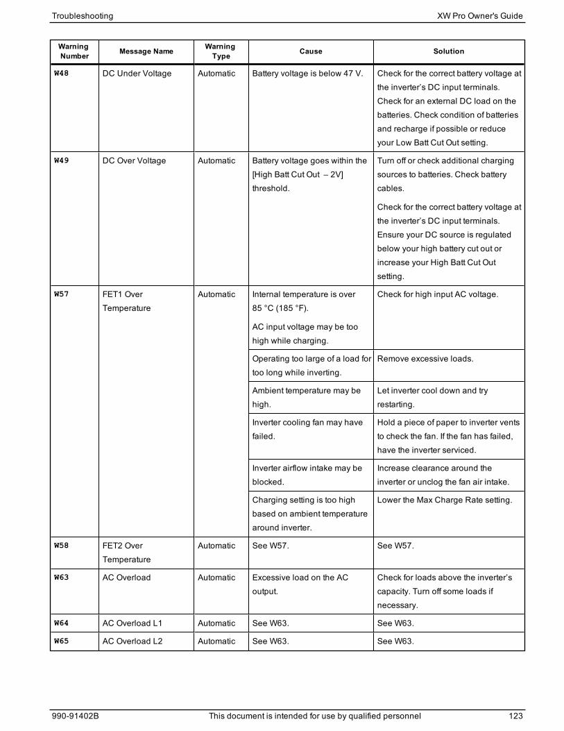
WarningNumber Message Name Warning
Type Cause Solution
W48 DC Under Voltage Automatic Battery voltage is below 47 V. Check for the correct battery voltage atthe inverter’s DC input terminals.Check for an external DC load on thebatteries. Check condition of batteriesand recharge if possible or reduceyour Low Batt Cut Out setting.
W49 DC Over Voltage Automatic Battery voltage goes within the [High Batt Cut Out – 2V]threshold.
Turn off or check additional chargingsources to batteries. Check batterycables.
Check for the correct battery voltage atthe inverter’s DC input terminals.Ensure your DC source is regulatedbelow your high battery cut out orincrease your High Batt Cut Outsetting.
W57 FET1 OverTemperature
Automatic Internal temperature is over85 °C (185 °F).
AC input voltage may be toohigh while charging.
Check for high input AC voltage.
Operating too large of a load fortoo long while inverting.
Remove excessive loads.
Ambient temperature may behigh.
Let inverter cool down and tryrestarting.
Inverter cooling fan may havefailed.
Hold a piece of paper to inverter ventsto check the fan. If the fan has failed,have the inverter serviced.
Inverter airflow intake may beblocked.
Increase clearance around theinverter or unclog the fan air intake.
Charging setting is too highbased on ambient temperaturearound inverter.
Lower the Max Charge Rate setting.
W58 FET2 OverTemperature
Automatic See W57. See W57.
W63 AC Overload Automatic Excessive load on the ACoutput.
Check for loads above the inverter’scapacity. Turn off some loads ifnecessary.
W64 AC Overload L1 Automatic See W63. See W63.
W65 AC Overload L2 Automatic See W63. See W63.
Troubleshooting XW Pro Owner's Guide
990-91402B This document is intended for use by qualified personnel 123
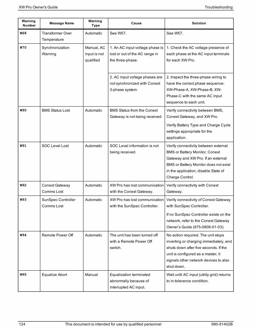
WarningNumber Message Name Warning
Type Cause Solution
W68 Transformer OverTemperature
Automatic See W57. See W57.
W70 SynchronizationWarning
Manual, ACinput is notqualified
1. An AC input voltage phase islost or out of the AC range inthe three-phase.
1. Check the AC voltage presence ofeach phase at the AC input terminalsfor each XW Pro.
2. AC input voltage phases arenot synchronized with Conext3-phase system.
2. Inspect the three-phase wiring tohave the correct phase sequence:XW-Phase-A, XW-Phase-B, XW-Phase-C with the same AC inputsequence to each unit.
W90 BMS Status Lost Automatic BMS Status from the ConextGateway is not being received.
Verify connectivity between BMS,Conext Gateway, and XW Pro.
Verify Battery Type and Charge Cyclesettings appropriate for theapplication.
W91 SOC Level Lost Automatic SOC Level information is notbeing received.
Verify connectivity between externalBMS or Battery Monitor, ConextGateway and XW Pro. If an externalBMS or Battery Monitor does not existin the application, disable State ofCharge Control.
W92 Conext GatewayComms Lost
Automatic XW Pro has lost communicationwith the Conext Gateway.
Verify connectivity with ConextGateway.
W93 SunSpec ControllerComms Lost
Automatic XW Pro has lost communicationwith the SunSpec Controller.
Verify connectivity of Conext Gatewaywith SunSpec Controller.
If no SunSpec Controller exists on thenetwork, refer to the Conext GatewayOwner’s Guide (975-0806-01-03).
W94 Remote Power Off Automatic The unit has been turned offwith a Remote Power Offswitch.
No action required. The unit stopsinverting or charging immediately, andshuts down after five seconds. If theunit is configured as a master, itsignals other network devices to alsoshut down.
W95 Equalize Abort Manual Equalization terminatedabnormally because ofinterrupted AC input.
Wait until AC input (utility grid) returnsto in-tolerance condition.
XW Pro Owner's Guide Troubleshooting
124 This document is intended for use by qualified personnel 990-91402B
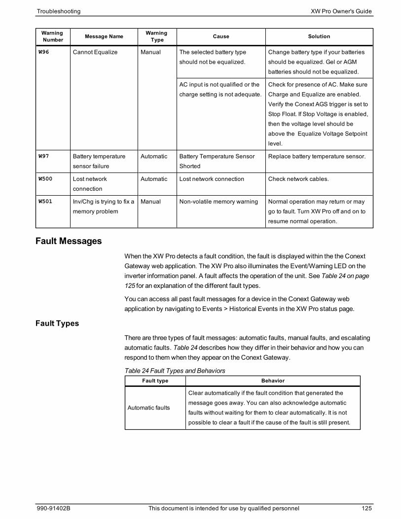
WarningNumber Message Name Warning
Type Cause Solution
W96 Cannot Equalize Manual The selected battery typeshould not be equalized.
Change battery type if your batteriesshould be equalized. Gel or AGMbatteries should not be equalized.
AC input is not qualified or thecharge setting is not adequate.
Check for presence of AC. Make sureCharge and Equalize are enabled.Verify the Conext AGS trigger is set toStop Float. If Stop Voltage is enabled,then the voltage level should beabove the Equalize Voltage Setpointlevel.
W97 Battery temperaturesensor failure
Automatic Battery Temperature SensorShorted
Replace battery temperature sensor.
W500 Lost networkconnection
Automatic Lost network connection Check network cables.
W501 Inv/Chg is trying to fix amemory problem
Manual Non-volatile memory warning Normal operation may return or maygo to fault. Turn XW Pro off and on toresume normal operation.
Fault MessagesWhen the XW Pro detects a fault condition, the fault is displayed within the the ConextGateway web application. The XW Pro also illuminates the Event/Warning LED on theinverter information panel. A fault affects the operation of the unit. See Table 24 on page125 for an explanation of the different fault types.
You can access all past fault messages for a device in the Conext Gateway webapplication by navigating to Events > Historical Events in the XW Pro status page.
Fault TypesThere are three types of fault messages: automatic faults, manual faults, and escalatingautomatic faults. Table 24 describes how they differ in their behavior and how you canrespond to them when they appear on the Conext Gateway.
Fault type Behavior
Automatic faults
Clear automatically if the fault condition that generated themessage goes away. You can also acknowledge automaticfaults without waiting for them to clear automatically. It is notpossible to clear a fault if the cause of the fault is still present.
Table 24 Fault Types and Behaviors
Troubleshooting XW Pro Owner's Guide
990-91402B This document is intended for use by qualified personnel 125
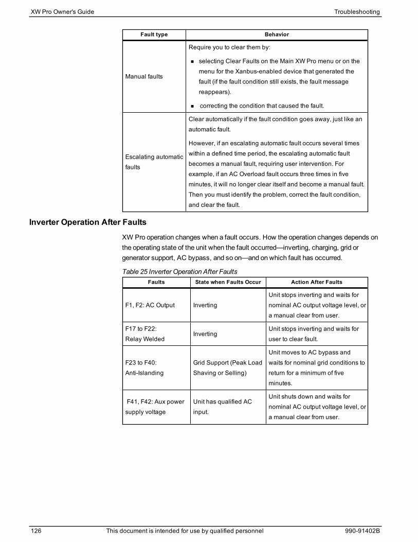
Fault type Behavior
Manual faults
Require you to clear them by:
n selecting Clear Faults on the Main XW Pro menu or on themenu for the Xanbus-enabled device that generated thefault (if the fault condition still exists, the fault messagereappears).
n correcting the condition that caused the fault.
Escalating automaticfaults
Clear automatically if the fault condition goes away, just like anautomatic fault.
However, if an escalating automatic fault occurs several timeswithin a defined time period, the escalating automatic faultbecomes a manual fault, requiring user intervention. Forexample, if an AC Overload fault occurs three times in fiveminutes, it will no longer clear itself and become a manual fault.Then you must identify the problem, correct the fault condition,and clear the fault.
Inverter Operation After FaultsXW Pro operation changes when a fault occurs. How the operation changes depends onthe operating state of the unit when the fault occurred—inverting, charging, grid orgenerator support, AC bypass, and so on—and on which fault has occurred.
Faults State when Faults Occur Action After Faults
F1, F2: AC Output InvertingUnit stops inverting and waits fornominal AC output voltage level, ora manual clear from user.
F17 to F22:Relay Welded
InvertingUnit stops inverting and waits foruser to clear fault.
F23 to F40:Anti-Islanding
Grid Support (Peak LoadShaving or Selling)
Unit moves to AC bypass andwaits for nominal grid conditions toreturn for a minimum of fiveminutes.
F41, F42: Aux powersupply voltage
Unit has qualified ACinput.
Unit shuts down and waits fornominal AC output voltage level, ora manual clear from user.
Table 25 Inverter Operation After Faults
XW Pro Owner's Guide Troubleshooting
126 This document is intended for use by qualified personnel 990-91402B
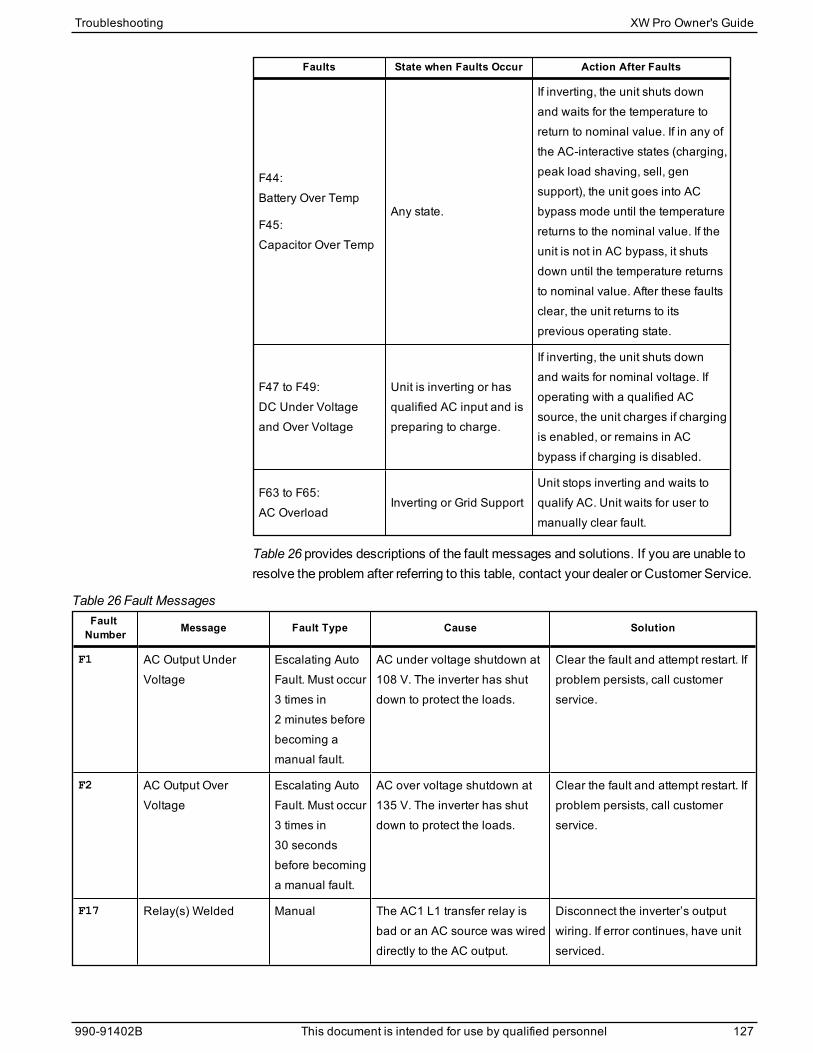
Faults State when Faults Occur Action After Faults
F44:Battery Over Temp
F45:Capacitor Over Temp
Any state.
If inverting, the unit shuts downand waits for the temperature toreturn to nominal value. If in any ofthe AC-interactive states (charging,peak load shaving, sell, gensupport), the unit goes into ACbypass mode until the temperaturereturns to the nominal value. If theunit is not in AC bypass, it shutsdown until the temperature returnsto nominal value. After these faultsclear, the unit returns to itsprevious operating state.
F47 to F49:DC Under Voltageand Over Voltage
Unit is inverting or hasqualified AC input and ispreparing to charge.
If inverting, the unit shuts downand waits for nominal voltage. Ifoperating with a qualified ACsource, the unit charges if chargingis enabled, or remains in ACbypass if charging is disabled.
F63 to F65:AC Overload
Inverting or Grid SupportUnit stops inverting and waits toqualify AC. Unit waits for user tomanually clear fault.
Table 26 provides descriptions of the fault messages and solutions. If you are unable toresolve the problem after referring to this table, contact your dealer or Customer Service.
FaultNumber Message Fault Type Cause Solution
F1 AC Output UnderVoltage
Escalating AutoFault. Must occur3 times in2 minutes beforebecoming amanual fault.
AC under voltage shutdown at108 V. The inverter has shutdown to protect the loads.
Clear the fault and attempt restart. Ifproblem persists, call customerservice.
F2 AC Output OverVoltage
Escalating AutoFault. Must occur3 times in30 secondsbefore becominga manual fault.
AC over voltage shutdown at135 V. The inverter has shutdown to protect the loads.
Clear the fault and attempt restart. Ifproblem persists, call customerservice.
F17 Relay(s) Welded Manual The AC1 L1 transfer relay isbad or an AC source was wireddirectly to the AC output.
Disconnect the inverter’s outputwiring. If error continues, have unitserviced.
Table 26 Fault Messages
Troubleshooting XW Pro Owner's Guide
990-91402B This document is intended for use by qualified personnel 127
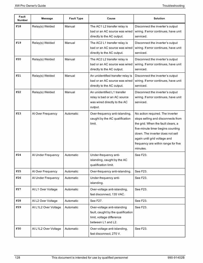
FaultNumber Message Fault Type Cause Solution
F18 Relay(s) Welded Manual The AC1 L2 transfer relay isbad or an AC source was wireddirectly to the AC output.
Disconnect the inverter’s outputwiring. If error continues, have unitserviced.
F19 Relay(s) Welded Manual The AC2 L1 transfer relay isbad or an AC source was wireddirectly to the AC output.
Disconnect the inverter’s outputwiring. If error continues, have unitserviced.
F20 Relay(s) Welded Manual The AC2 L2 transfer relay isbad or an AC source was wireddirectly to the AC output.
Disconnect the inverter’s outputwiring. If error continues, have unitserviced.
F21 Relay(s) Welded Manual An unidentified transfer relay isbad or an AC source was wireddirectly to the AC output.
Disconnect the inverter’s outputwiring. If error continues, have unitserviced.
F22 Relay(s) Welded Manual An unidentified L1 transferrelay is bad or an AC sourcewas wired directly to the ACoutput.
Disconnect the inverter’s outputwiring. If error continues, have unitserviced.
F23 AI Over Frequency Automatic Over-frequency anti-islanding,caught by the AC qualificationlimit.
No action required. The inverterstops selling and disconnects fromthe grid. When the fault clears, afive-minute timer begins countingdown. The inverter does not sellagain until grid voltage andfrequency are within range for fiveminutes.
F24 AI Under Frequency Automatic Under-frequency anti-islanding, caught by the ACqualification limit.
See F23.
F25 AI Over Frequency Automatic Over-frequency anti-islanding. See F23.
F26 AI Under Frequency Automatic Under-frequency anti-islanding.
See F23.
F27 AI L1 Over Voltage Automatic Over-voltage anti-islanding,fast disconnect, 135 VAC.
See F23.
F28 AI L2 Over Voltage Automatic See F27. See F23.
F29 AI L1L2 Over Voltage Automatic Over-voltage anti-islandingfault, caught by the qualificationlimit, voltage differencebetween L1 and L2.
See F23.
F30 AI L1L2 Over Voltage Automatic Over-voltage anti-islanding,fast disconnect, 270 V.
See F23.
XW Pro Owner's Guide Troubleshooting
128 This document is intended for use by qualified personnel 990-91402B
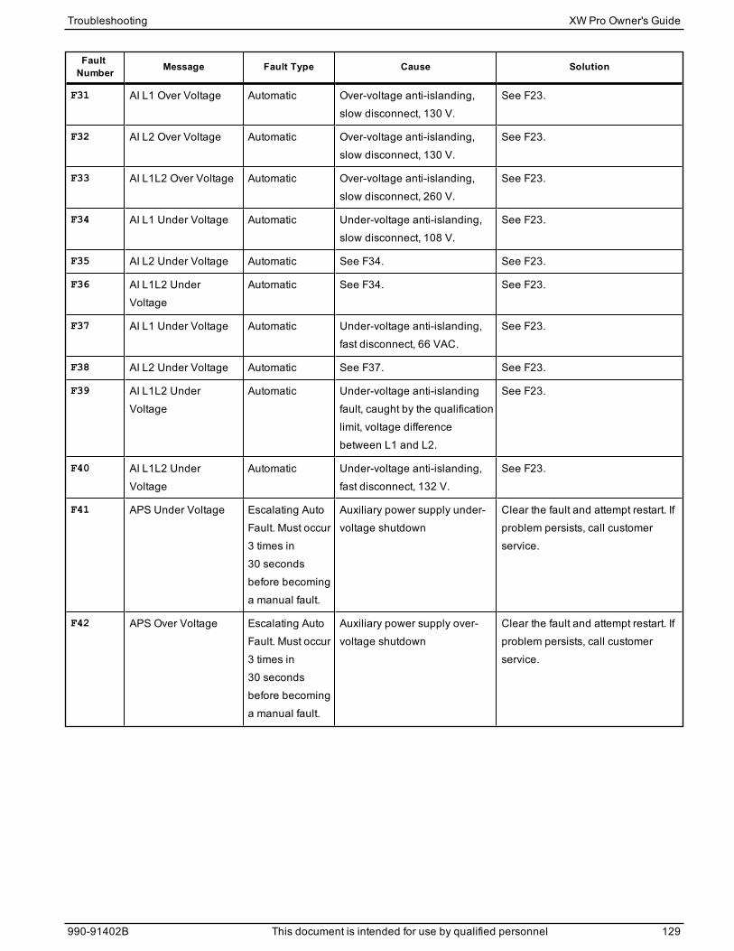
FaultNumber Message Fault Type Cause Solution
F31 AI L1 Over Voltage Automatic Over-voltage anti-islanding,slow disconnect, 130 V.
See F23.
F32 AI L2 Over Voltage Automatic Over-voltage anti-islanding,slow disconnect, 130 V.
See F23.
F33 AI L1L2 Over Voltage Automatic Over-voltage anti-islanding,slow disconnect, 260 V.
See F23.
F34 AI L1 Under Voltage Automatic Under-voltage anti-islanding,slow disconnect, 108 V.
See F23.
F35 AI L2 Under Voltage Automatic See F34. See F23.
F36 AI L1L2 UnderVoltage
Automatic See F34. See F23.
F37 AI L1 Under Voltage Automatic Under-voltage anti-islanding,fast disconnect, 66 VAC.
See F23.
F38 AI L2 Under Voltage Automatic See F37. See F23.
F39 AI L1L2 UnderVoltage
Automatic Under-voltage anti-islandingfault, caught by the qualificationlimit, voltage differencebetween L1 and L2.
See F23.
F40 AI L1L2 UnderVoltage
Automatic Under-voltage anti-islanding,fast disconnect, 132 V.
See F23.
F41 APS Under Voltage Escalating AutoFault. Must occur3 times in30 secondsbefore becominga manual fault.
Auxiliary power supply under-voltage shutdown
Clear the fault and attempt restart. Ifproblem persists, call customerservice.
F42 APS Over Voltage Escalating AutoFault. Must occur3 times in30 secondsbefore becominga manual fault.
Auxiliary power supply over-voltage shutdown
Clear the fault and attempt restart. Ifproblem persists, call customerservice.
Troubleshooting XW Pro Owner's Guide
990-91402B This document is intended for use by qualified personnel 129
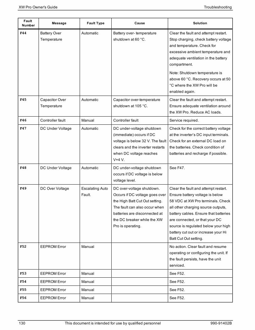
FaultNumber Message Fault Type Cause Solution
F44 Battery OverTemperature
Automatic Battery over- temperatureshutdown at 60 °C.
Clear the fault and attempt restart.Stop charging, check battery voltageand temperature. Check forexcessive ambient temperature andadequate ventilation in the batterycompartment.
Note: Shutdown temperature isabove 60 °C. Recovery occurs at 50°C where the XW Pro will beenabled again.
F45 Capacitor OverTemperature
Automatic Capacitor over-temperatureshutdown at 105 °C.
Clear the fault and attempt restart.Ensure adequate ventilation aroundthe XW Pro. Reduce AC loads.
F46 Controller fault Manual Controller fault Service required.
F47 DC Under Voltage Automatic DC under-voltage shutdown(immediate) occurs if DCvoltage is below 32 V. The faultclears and the inverter restartswhen DC voltage reachesV+4 V.
Check for the correct battery voltageat the inverter’s DC input terminals.Check for an external DC load onthe batteries. Check condition ofbatteries and recharge if possible.
F48 DC Under Voltage Automatic DC under-voltage shutdownoccurs if DC voltage is belowvoltage level.
See F47.
F49 DC Over Voltage Escalating AutoFault.
DC over-voltage shutdown.Occurs if DC voltage goes overthe High Batt Cut Out setting.The fault can also occur whenbatteries are disconnected atthe DC breaker while the XWPro is operating.
Clear the fault and attempt restart.Ensure battery voltage is below58 VDC at XW Pro terminals. Checkall other charging source outputs,battery cables. Ensure that batteriesare connected, or that your DCsource is regulated below your highbattery cut out or increase your HiBatt Cut Out setting.
F52 EEPROM Error Manual No action. Clear fault and resumeoperating or configuring the unit. Ifthe fault persists, have the unitserviced.
F53 EEPROM Error Manual See F52.
F54 EEPROM Error Manual See F52.
F55 EEPROM Error Manual See F52.
F56 EEPROM Error Manual See F52.
XW Pro Owner's Guide Troubleshooting
130 This document is intended for use by qualified personnel 990-91402B
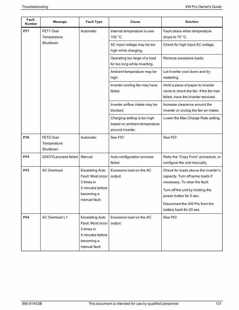
FaultNumber Message Fault Type Cause Solution
F57 FET1 OverTemperatureShutdown
Automatic Internal temperature is over105 °C.
Fault clears when temperaturedrops to 75 °C.
AC input voltage may be toohigh while charging.
Check for high input AC voltage.
Operating too large of a loadfor too long while inverting.
Remove excessive loads.
Ambient temperature may behigh.
Let inverter cool down and tryrestarting.
Inverter cooling fan may havefailed.
Hold a piece of paper to invertervents to check the fan. If the fan hasfailed, have the inverter serviced.
Inverter airflow intake may beblocked.
Increase clearance around theinverter or unclog the fan air intake.
Charging setting is too highbased on ambient temperaturearound inverter.
Lower the Max Charge Rate setting.
F58 FET2 OverTemperatureShutdown
Automatic See F57. See F57.
F59 GOCFG process failed Manual Auto-configuration processfailed.
Retry the “Copy From” procedure, orconfigure the unit manually.
F63 AC Overload Escalating AutoFault. Must occur3 times in5 minutes beforebecoming amanual fault.
Excessive load on the ACoutput.
Check for loads above the inverter’scapacity. Turn off some loads ifnecessary. To clear the fault:
Turn off the unit by holding thepower button for 5 sec.
Disconnect the XW Pro from thebattery bank for 20 sec.
F64 AC Overload L1 Escalating AutoFault. Must occur3 times in5 minutes beforebecoming amanual fault.
Excessive load on the ACoutput.
See F63
Troubleshooting XW Pro Owner's Guide
990-91402B This document is intended for use by qualified personnel 131
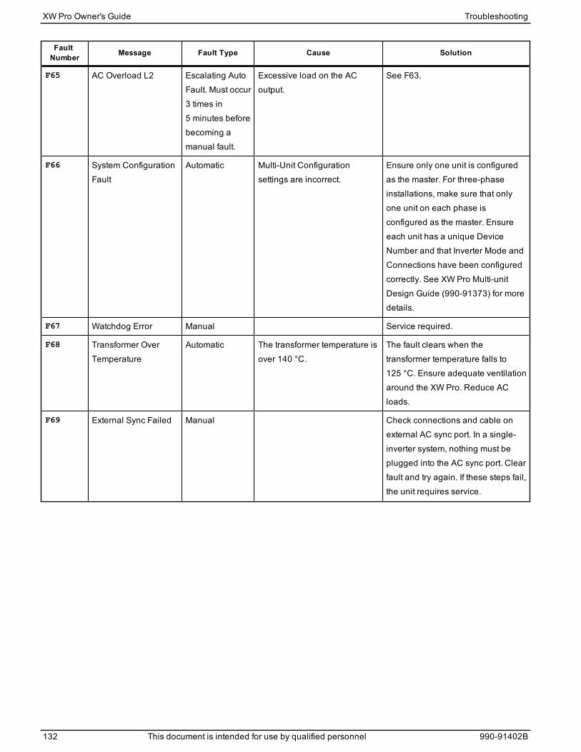
FaultNumber Message Fault Type Cause Solution
F65 AC Overload L2 Escalating AutoFault. Must occur3 times in5 minutes beforebecoming amanual fault.
Excessive load on the ACoutput.
See F63.
F66 System ConfigurationFault
Automatic Multi-Unit Configurationsettings are incorrect.
Ensure only one unit is configuredas the master. For three-phaseinstallations, make sure that onlyone unit on each phase isconfigured as the master. Ensureeach unit has a unique DeviceNumber and that Inverter Mode andConnections have been configuredcorrectly. See XW Pro Multi-unitDesign Guide (990-91373) for moredetails.
F67 Watchdog Error Manual Service required.
F68 Transformer OverTemperature
Automatic The transformer temperature isover 140 °C.
The fault clears when thetransformer temperature falls to125 °C. Ensure adequate ventilationaround the XW Pro. Reduce ACloads.
F69 External Sync Failed Manual Check connections and cable onexternal AC sync port. In a single-inverter system, nothing must beplugged into the AC sync port. Clearfault and try again. If these steps fail,the unit requires service.
XW Pro Owner's Guide Troubleshooting
132 This document is intended for use by qualified personnel 990-91402B
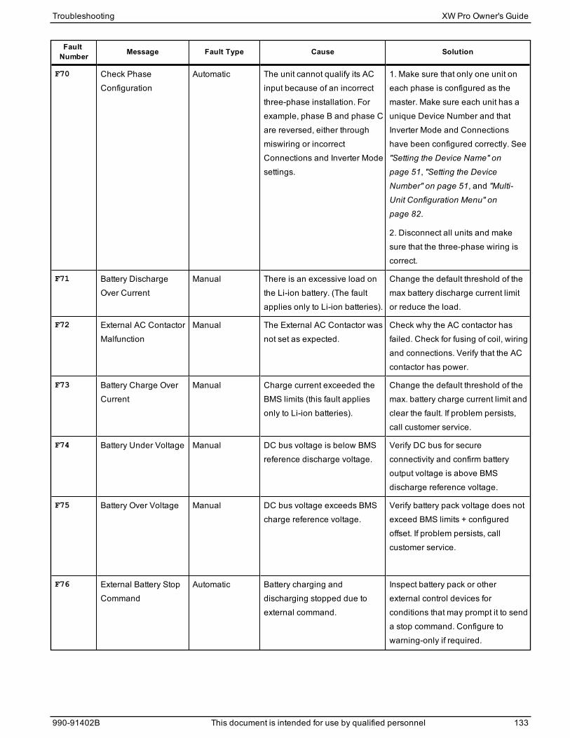
FaultNumber Message Fault Type Cause Solution
F70 Check PhaseConfiguration
Automatic The unit cannot qualify its ACinput because of an incorrectthree-phase installation. Forexample, phase B and phase Care reversed, either throughmiswiring or incorrectConnections and Inverter Modesettings.
1. Make sure that only one unit oneach phase is configured as themaster. Make sure each unit has aunique Device Number and thatInverter Mode and Connectionshave been configured correctly. See"Setting the Device Name" on
page 51, "Setting the DeviceNumber" on page 51, and "Multi-Unit Configuration Menu" on
page 82.
2. Disconnect all units and makesure that the three-phase wiring iscorrect.
F71 Battery DischargeOver Current
Manual There is an excessive load onthe Li-ion battery. (The faultapplies only to Li-ion batteries).
Change the default threshold of themax battery discharge current limitor reduce the load.
F72 External AC ContactorMalfunction
Manual The External AC Contactor wasnot set as expected.
Check why the AC contactor hasfailed. Check for fusing of coil, wiringand connections. Verify that the ACcontactor has power.
F73 Battery Charge OverCurrent
Manual Charge current exceeded theBMS limits (this fault appliesonly to Li-ion batteries).
Change the default threshold of themax. battery charge current limit andclear the fault. If problem persists,call customer service.
F74 Battery Under Voltage Manual DC bus voltage is below BMSreference discharge voltage.
Verify DC bus for secureconnectivity and confirm batteryoutput voltage is above BMSdischarge reference voltage.
F75 Battery Over Voltage Manual DC bus voltage exceeds BMScharge reference voltage.
Verify battery pack voltage does notexceed BMS limits + configuredoffset. If problem persists, callcustomer service.
F76 External Battery StopCommand
Automatic Battery charging anddischarging stopped due toexternal command.
Inspect battery pack or otherexternal control devices forconditions that may prompt it to senda stop command. Configure towarning-only if required.
Troubleshooting XW Pro Owner's Guide
990-91402B This document is intended for use by qualified personnel 133
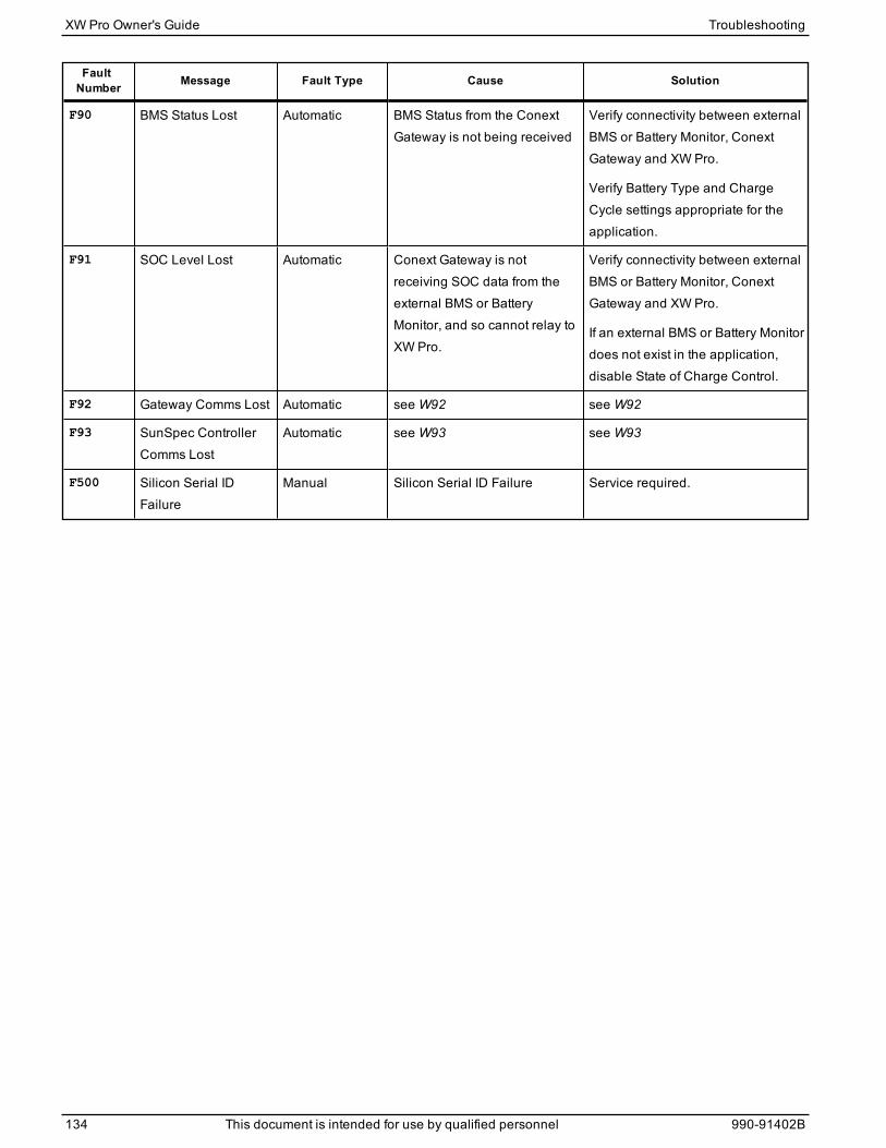
FaultNumber Message Fault Type Cause Solution
F90 BMS Status Lost Automatic BMS Status from the ConextGateway is not being received
Verify connectivity between externalBMS or Battery Monitor, ConextGateway and XW Pro.
Verify Battery Type and ChargeCycle settings appropriate for theapplication.
F91 SOC Level Lost Automatic Conext Gateway is notreceiving SOC data from theexternal BMS or BatteryMonitor, and so cannot relay toXW Pro.
Verify connectivity between externalBMS or Battery Monitor, ConextGateway and XW Pro.
If an external BMS or Battery Monitordoes not exist in the application,disable State of Charge Control.
F92 Gateway Comms Lost Automatic seeW92 seeW92
F93 SunSpec ControllerComms Lost
Automatic seeW93 seeW93
F500 Silicon Serial IDFailure
Manual Silicon Serial ID Failure Service required.
XW Pro Owner's Guide Troubleshooting
134 This document is intended for use by qualified personnel 990-91402B

Specifications6
Appendix A: Specifications 136Electrical Specifications 136
Mechanical and Regulatory Specifications 138XW ProOverload Capability 140Output Power Versus Ambient Temperature 141XW Pro Efficiency 142
What's in This Chapter?
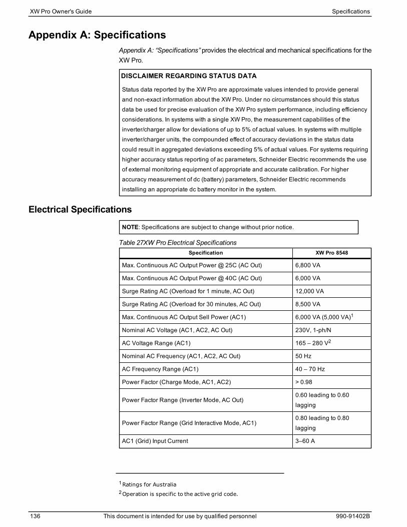
Appendix A: SpecificationsAppendix A: “Specifications” provides the electrical andmechanical specifications for theXW Pro.
DISCLAIMER REGARDING STATUS DATA
Status data reported by the XW Pro are approximate values intended to provide generaland non-exact information about the XW Pro. Under no circumstances should this statusdata be used for precise evaluation of the XW Pro system performance, including efficiencyconsiderations. In systems with a single XW Pro, the measurement capabilities of theinverter/charger allow for deviations of up to 5% of actual values. In systems with multipleinverter/charger units, the compounded effect of accuracy deviations in the status datacould result in aggregated deviations exceeding 5% of actual values. For systems requiringhigher accuracy status reporting of ac parameters, Schneider Electric recommends the useof external monitoring equipment of appropriate and accurate calibration. For higheraccuracy measurement of dc (battery) parameters, Schneider Electric recommendsinstalling an appropriate dc battery monitor in the system.
Electrical SpecificationsNOTE: Specifications are subject to change without prior notice.
Specification XW Pro 8548
Max. Continuous AC Output Power @ 25C (AC Out) 6,800 VA
Max. Continuous AC Output Power @ 40C (AC Out) 6,000 VA
Surge Rating AC (Overload for 1 minute, AC Out) 12,000 VA
Surge Rating AC (Overload for 30 minutes, AC Out) 8,500 VA
Max. Continuous AC Output Sell Power (AC1) 6,000 VA (5,000 VA)1
Nominal AC Voltage (AC1, AC2, AC Out) 230V, 1-ph/N
AC Voltage Range (AC1) 165 – 280 V2
Nominal AC Frequency (AC1, AC2, AC Out) 50 Hz
AC Frequency Range (AC1) 40 – 70 Hz
Power Factor (Charge Mode, AC1, AC2) > 0.98
Power Factor Range (Inverter Mode, AC Out)0.60 leading to 0.60lagging
Power Factor Range (Grid Interactive Mode, AC1)0.80 leading to 0.80lagging
AC1 (Grid) Input Current 3–60 A
Table 27XW Pro Electrical Specifications
1Ratings for Australia2Operation is specific to the active grid code.
XW Pro Owner's Guide Specifications
136 This document is intended for use by qualified personnel 990-91402B
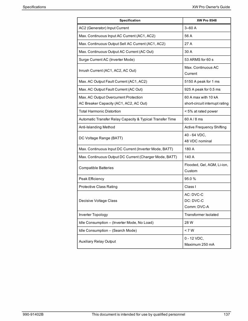
Specification XW Pro 8548
AC2 (Generator) Input Current 3–60 A
Max. Continuous Input AC Current (AC1, AC2) 56 A
Max. Continuous Output Sell AC Current (AC1, AC2) 27 A
Max. Continuous Output AC Current (AC Out) 30 A
Surge Current AC (Inverter Mode) 53 ARMS for 60 s
Inrush Current (AC1, AC2, AC Out)Max. Continuous ACCurrent
Max. AC Output Fault Current (AC1, AC2) 5150 A peak for 1 ms
Max. AC Output Fault Current (AC Out) 925 A peak for 0.5 ms
Max. AC Output Overcurrent ProtectionAC Breaker Capacity (AC1, AC2, AC Out)
60 A max with 10 kAshort-circuit interrupt rating
Total Harmonic Distortion < 5% at rated power
Automatic Transfer Relay Capacity & Typical Transfer Time 60 A / 8 ms
Anti-Islanding Method Active Frequency Shifting
DC Voltage Range (BATT)40 - 64 VDC,48 VDC nominal
Max. Continuous Input DC Current (Inverter Mode, BATT) 180 A
Max. Continuous Output DC Current (Charger Mode, BATT) 140 A
Compatible BatteriesFlooded, Gel, AGM, Li-ion,Custom
Peak Efficiency 95.0 %
Protective Class Rating Class I
Decisive Voltage ClassAC: DVC-CDC: DVC-CComm: DVC-A
Inverter Topology Transformer Isolated
Idle Consumption – (Inverter Mode, No Load) 28 W
Idle Consumption – (Search Mode) < 7 W
Auxiliary Relay Output0 - 12 VDC,Maximum 250 mA
Specifications XW Pro Owner's Guide
990-91402B This document is intended for use by qualified personnel 137
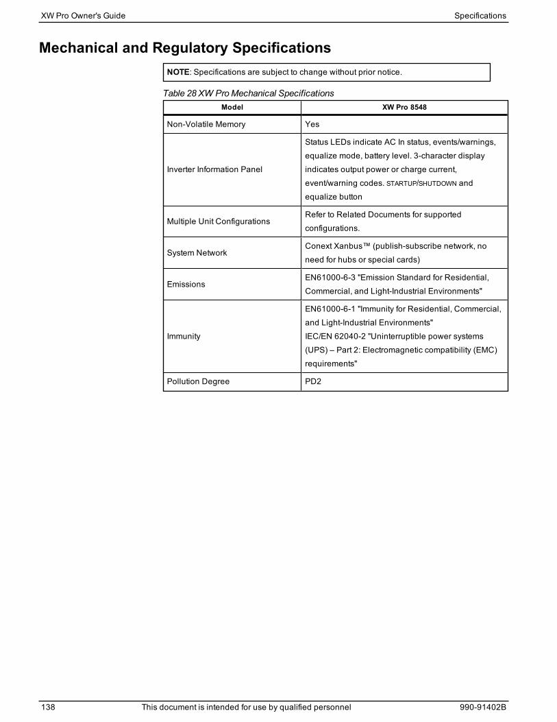
Mechanical and Regulatory SpecificationsNOTE: Specifications are subject to change without prior notice.
Model XW Pro 8548
Non-Volatile Memory Yes
Inverter Information Panel
Status LEDs indicate AC In status, events/warnings,equalize mode, battery level. 3-character displayindicates output power or charge current,event/warning codes. STARTUP/SHUTDOWN andequalize button
Multiple Unit ConfigurationsRefer to Related Documents for supportedconfigurations.
System NetworkConext Xanbus™ (publish-subscribe network, noneed for hubs or special cards)
EmissionsEN61000-6-3 "Emission Standard for Residential,Commercial, and Light-Industrial Environments"
Immunity
EN61000-6-1 "Immunity for Residential, Commercial,and Light-Industrial Environments"IEC/EN 62040-2 "Uninterruptible power systems(UPS) – Part 2: Electromagnetic compatibility (EMC)requirements"
Pollution Degree PD2
Table 28 XW ProMechanical Specifications
XW Pro Owner's Guide Specifications
138 This document is intended for use by qualified personnel 990-91402B

Model XW Pro 8548
Regulatory approvals
CE marked and complies with:
Low Voltage Directive 2014/35/EU, per:
n EN62109-1 Power converters used in photovoltaicsystems
n EN62109-2 Particular requirements for Inverters
n ENG60529 Degrees of protection by enclosures
n AS 62040-1
EMC Directive 2014/30/EU, per:
n EN61000-6-3 "Emission Standard for Residential,Commercial, and Light-Industrial Environments"
n EN61000-6-1 "Immunity for Residential,Commercial, and Light-Industrial Environments"
n IEC/EN 62040-2 "Uninterruptible power systems(UPS) – Part 2: Electromagnetic compatibility(EMC) requirements"
ROHS Directive 2011/65/EU - Restriction ofHazardous Substances
n EN 50581:2012 Technical documentation for theassessment of hazardous substances
RCM marked and complies with:
n AS NZS 4777.2:2015 "Inverter Requirements"
n IEC 62109-1:2010 "General Requirements"
n IEC 62109-2:2011 "Particular Requirements forInverters"
n AS 62040.1: 2019 "Uninterruptible power systems(UPS) – art 1: Safety requirements"
n IEC/EN 62116: 2014 "Utility-interconnectedphotovoltaic inverters – Test procedure ofislanding prevention measures"
n Registered with the Clean Energy Council
Enclosure Type IP20— Indoor use only
Rated Temperature Range(meets specifications)
0–25 °C
Operational Temperature Range -25–65 °C
Storage Temperature Range -40–85 °C
Operational Humidity Range 5 – 95 % Non-Condensing
Altitude Sea level up to 2000 m
Specifications XW Pro Owner's Guide
990-91402B This document is intended for use by qualified personnel 139
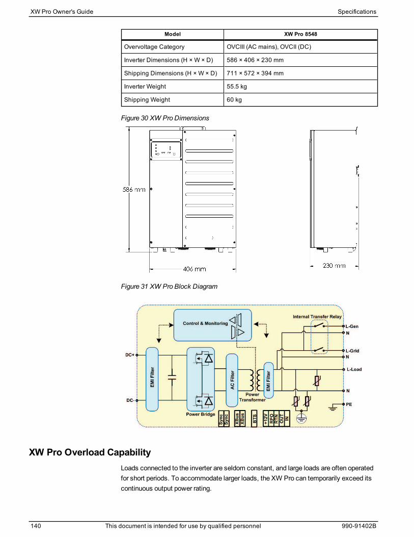
Model XW Pro 8548
Overvoltage Category OVCIII (AC mains), OVCII (DC)
Inverter Dimensions (H × W × D) 586 × 406 × 230 mm
Shipping Dimensions (H × W × D) 711 × 572 × 394 mm
Inverter Weight 55.5 kg
Shipping Weight 60 kg
Figure 30 XW Pro Dimensions
Figure 31 XW Pro Block Diagram
XW Pro Overload CapabilityLoads connected to the inverter are seldom constant, and large loads are often operatedfor short periods. To accommodate larger loads, the XW Pro can temporarily exceed itscontinuous output power rating.
XW Pro Owner's Guide Specifications
140 This document is intended for use by qualified personnel 990-91402B
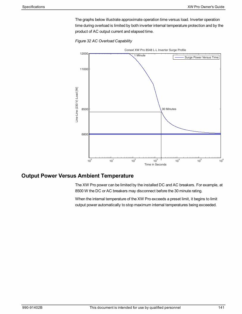
The graphs below illustrate approximate operation time versus load. Inverter operationtime during overload is limited by both inverter internal temperature protection and by theproduct of AC output current and elapsed time.
Figure 32 AC Overload Capability
6800
8500
11000
12000
Lin
e-L
ine
(2
30
V)
Lo
ad
[W
]
Conext XW Pro 8548 L-L Inverter Surge Profile
1 Minute
30 Minutes
Surge Power Versus Time
100
101
102
103
104
105
106
Time in Seconds
Output Power Versus Ambient TemperatureThe XW Pro power can be limited by the installed DC and AC breakers. For example, at8500W the DC or AC breakers may disconnect before the 30minute rating.
When the internal temperature of the XW Pro exceeds a preset limit, it begins to limitoutput power automatically to stopmaximum internal temperatures being exceeded.
Specifications XW Pro Owner's Guide
990-91402B This document is intended for use by qualified personnel 141

Figure 33 Output Power Versus Ambient Temperature
XW Pro EfficiencyInverting Efficiency (Typical)
Figure 34 Inverting Efficiency (typical)
XW Pro Owner's Guide Specifications
142 This document is intended for use by qualified personnel 990-91402B
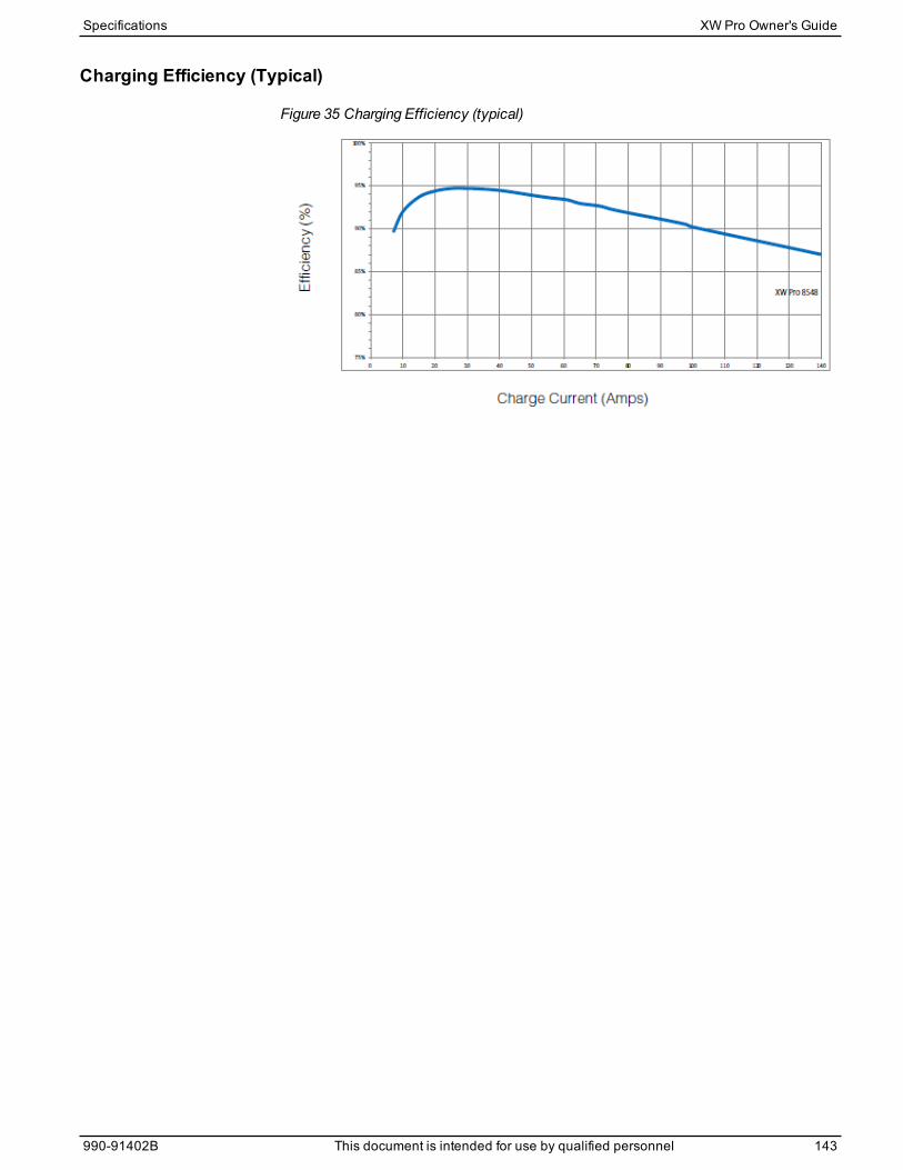
Charging Efficiency (Typical)
Figure 35 Charging Efficiency (typical)
Specifications XW Pro Owner's Guide
990-91402B This document is intended for use by qualified personnel 143

Defaults7
Default Settings 146
What's in This Chapter?

Default SettingsThis section contains the default configuration settings and ranges for the XW Pro.Configuration settings can be viewed and changed using the Conext Gateway webapplication.
Controls Settings Menu
Item Default Setting Range Step Size
Operating Mode Standby Standby/Operating n/a
Inverter
Enable/DisableEnabled Enabled/Disabled n/a
Grid Support Sell
Enable/DisableEnabled Enabled/Disabled n/a
Charger
Enable/DisableEnabled Enabled/Disabled n/a
Inverter Settings Menu
Item Default Setting Range Step Size
Low Battery Cut Out 44 V 36–48 V 0.1
LBCO Hysteresis 2 V 0-10 V 0.1
LBCO Delay 10s 0–600s 1
High Battery Cut
Out65 V 58–70 V 0.1
High SOC Cut Out 99% 0–100% 1
High SOC Cut Out
Delay60s 0–300s 1
Low Battery Cut Out
SOC25% 0–100% 1
Low Battery Cut Out
SOC Delay60s 0–300s 1
Search Mode Disabled Enabled/Disabled n/a
Search Watts 50 W 25–255 W 5
Search Delay 2s 1–25s 1
Action on
Communication LossHeartbeat Disabled
Heartbeat Disabled
Do Nothing
Autonomous Operation
AC Passthrough
n/a
XW Pro Owner's Guide Defaults
146 This document is intended for use by qualified personnel 990-91402B
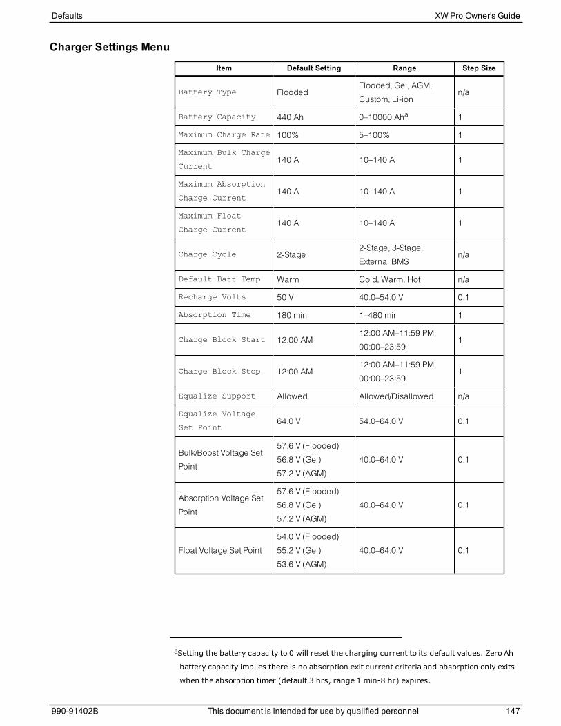
Charger Settings Menu
Item Default Setting Range Step Size
Battery Type FloodedFlooded, Gel, AGM,
Custom, Li-ionn/a
Battery Capacity 440 Ah 0–10000 Aha 1
Maximum Charge Rate 100% 5–100% 1
Maximum Bulk Charge
Current140 A 10–140 A 1
Maximum Absorption
Charge Current140 A 10–140 A 1
Maximum Float
Charge Current140 A 10–140 A 1
Charge Cycle 2-Stage2-Stage, 3-Stage,
External BMSn/a
Default Batt Temp Warm Cold, Warm, Hot n/a
Recharge Volts 50 V 40.0–54.0 V 0.1
Absorption Time 180 min 1–480 min 1
Charge Block Start 12:00 AM12:00 AM–11:59 PM,
00:00–23:591
Charge Block Stop 12:00 AM12:00 AM–11:59 PM,
00:00–23:591
Equalize Support Allowed Allowed/Disallowed n/a
Equalize Voltage
Set Point64.0 V 54.0–64.0 V 0.1
Bulk/Boost Voltage Set
Point
57.6 V (Flooded)
56.8 V (Gel)
57.2 V (AGM)
40.0–64.0 V 0.1
Absorption Voltage Set
Point
57.6 V (Flooded)
56.8 V (Gel)
57.2 V (AGM)
40.0–64.0 V 0.1
Float Voltage Set Point
54.0 V (Flooded)
55.2 V (Gel)
53.6 V (AGM)
40.0–64.0 V 0.1
aSetting the battery capacity to 0 will reset the charging current to its default values. Zero Ah
battery capacity implies there is no absorption exit current criteria and absorption only exits
when the absorption timer (default 3 hrs, range 1 min-8 hr) expires.
Defaults XW Pro Owner's Guide
990-91402B This document is intended for use by qualified personnel 147
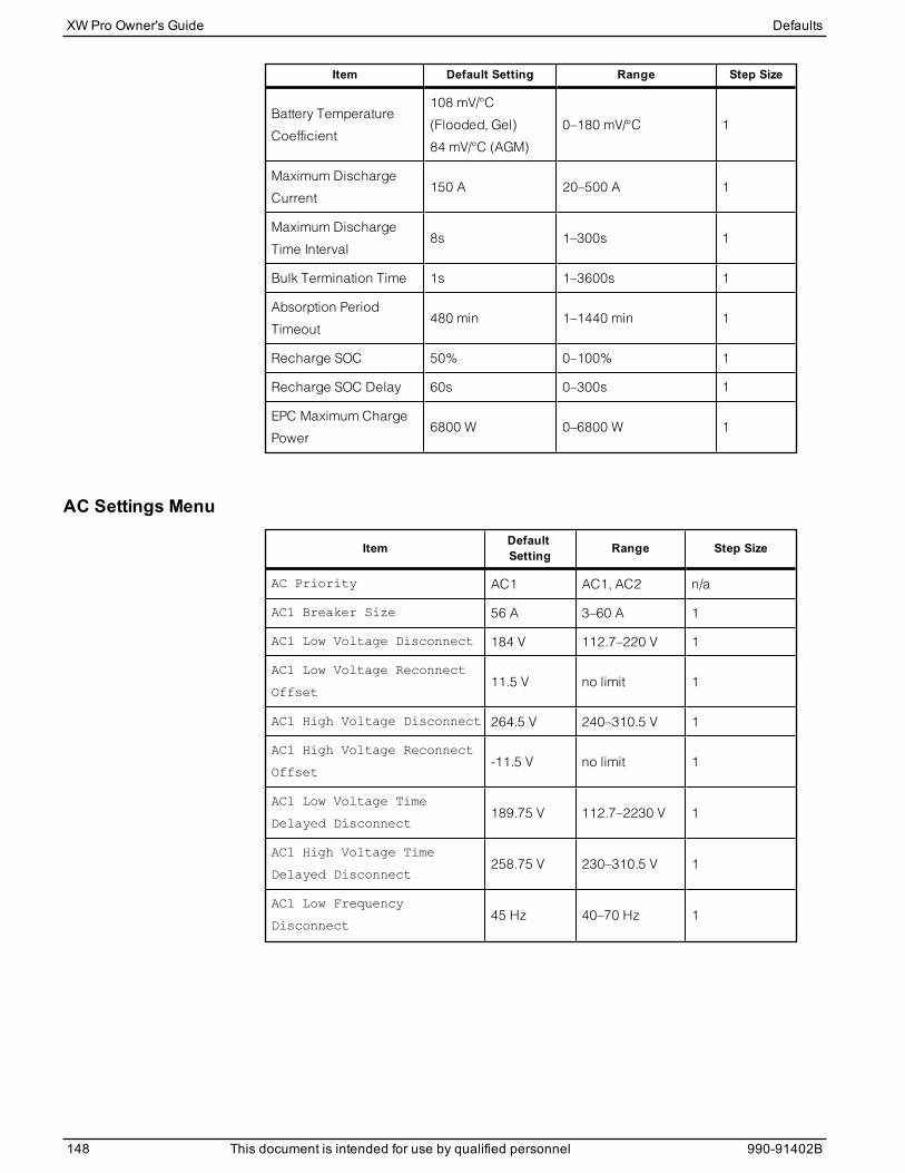
Item Default Setting Range Step Size
Battery Temperature
Coefficient
108 mV/°C
(Flooded, Gel)
84 mV/°C (AGM)
0–180 mV/°C 1
Maximum Discharge
Current150 A 20–500 A 1
Maximum Discharge
Time Interval8s 1–300s 1
Bulk Termination Time 1s 1–3600s 1
Absorption Period
Timeout480 min 1–1440 min 1
Recharge SOC 50% 0–100% 1
Recharge SOC Delay 60s 0–300s 1
EPC Maximum Charge
Power6800 W 0–6800 W 1
AC Settings Menu
Item DefaultSetting Range Step Size
AC Priority AC1 AC1, AC2 n/a
AC1 Breaker Size 56 A 3–60 A 1
AC1 Low Voltage Disconnect 184 V 112.7–220 V 1
AC1 Low Voltage Reconnect
Offset11.5 V no limit 1
AC1 High Voltage Disconnect 264.5 V 240–310.5 V 1
AC1 High Voltage Reconnect
Offset-11.5 V no limit 1
AC1 Low Voltage Time
Delayed Disconnect189.75 V 112.7–2230 V 1
AC1 High Voltage Time
Delayed Disconnect258.75 V 230–310.5 V 1
AC1 Low Frequency
Disconnect45 Hz 40–70 Hz 1
XW Pro Owner's Guide Defaults
148 This document is intended for use by qualified personnel 990-91402B
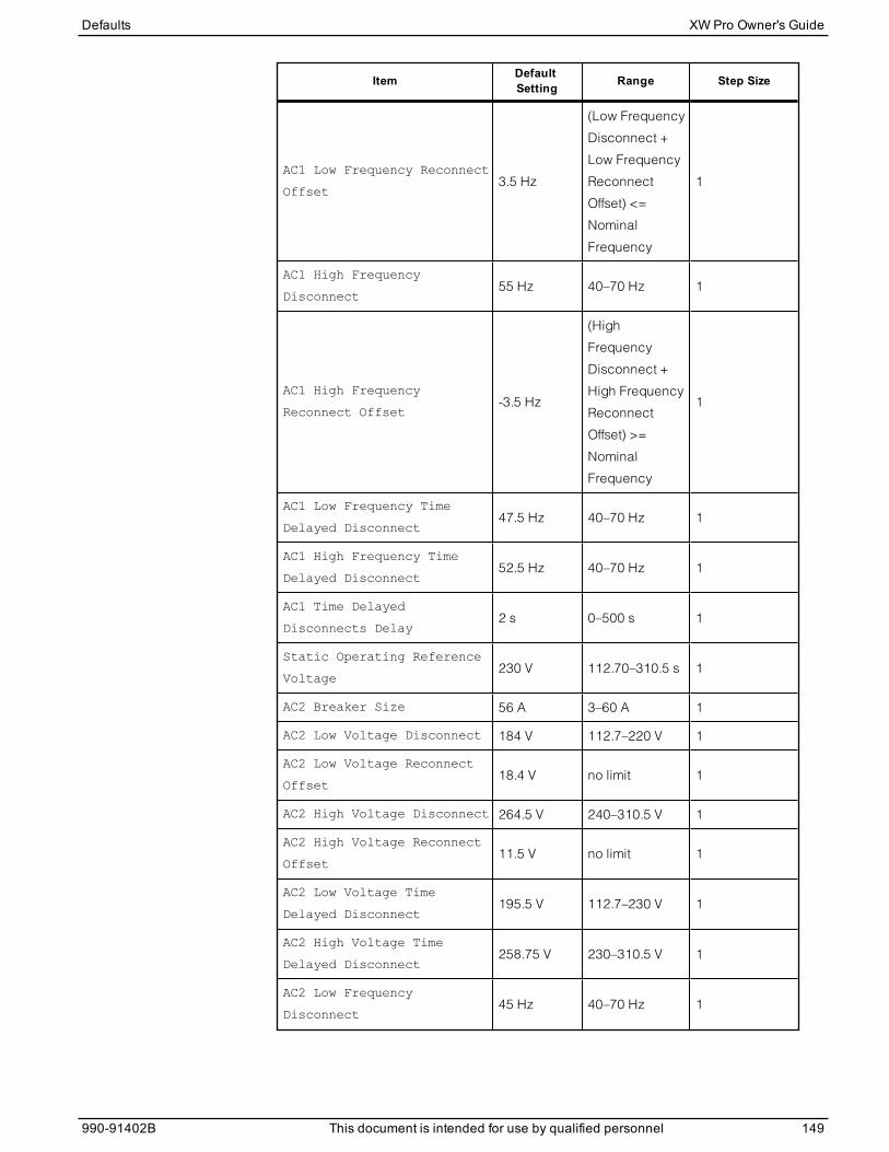
Item DefaultSetting Range Step Size
AC1 Low Frequency Reconnect
Offset3.5 Hz
(Low Frequency
Disconnect +
Low Frequency
Reconnect
Offset) <=
Nominal
Frequency
1
AC1 High Frequency
Disconnect55 Hz 40–70 Hz 1
AC1 High Frequency
Reconnect Offset-3.5 Hz
(High
Frequency
Disconnect +
High Frequency
Reconnect
Offset) >=
Nominal
Frequency
1
AC1 Low Frequency Time
Delayed Disconnect47.5 Hz 40–70 Hz 1
AC1 High Frequency Time
Delayed Disconnect52.5 Hz 40–70 Hz 1
AC1 Time Delayed
Disconnects Delay2 s 0–500 s 1
Static Operating Reference
Voltage230 V 112.70–310.5 s 1
AC2 Breaker Size 56 A 3–60 A 1
AC2 Low Voltage Disconnect 184 V 112.7–220 V 1
AC2 Low Voltage Reconnect
Offset18.4 V no limit 1
AC2 High Voltage Disconnect 264.5 V 240–310.5 V 1
AC2 High Voltage Reconnect
Offset11.5 V no limit 1
AC2 Low Voltage Time
Delayed Disconnect195.5 V 112.7–230 V 1
AC2 High Voltage Time
Delayed Disconnect258.75 V 230–310.5 V 1
AC2 Low Frequency
Disconnect45 Hz 40–70 Hz 1
Defaults XW Pro Owner's Guide
990-91402B This document is intended for use by qualified personnel 149
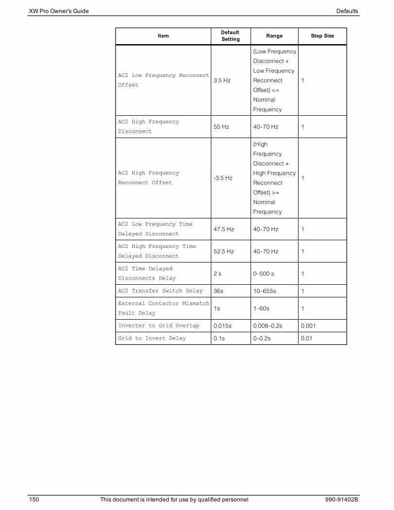
Item DefaultSetting Range Step Size
AC2 Low Frequency Reconnect
Offset3.5 Hz
(Low Frequency
Disconnect +
Low Frequency
Reconnect
Offset) <=
Nominal
Frequency
1
AC2 High Frequency
Disconnect55 Hz 40–70 Hz 1
AC2 High Frequency
Reconnect Offset-3.5 Hz
(High
Frequency
Disconnect +
High Frequency
Reconnect
Offset) >=
Nominal
Frequency
1
AC2 Low Frequency Time
Delayed Disconnect47.5 Hz 40–70 Hz 1
AC2 High Frequency Time
Delayed Disconnect52.5 Hz 40–70 Hz 1
AC2 Time Delayed
Disconnects Delay2 s 0–500 s 1
AC2 Transfer Switch Delay 36s 10–655s 1
External Contactor Mismatch
Fault Delay1s 1–60s 1
Inverter to Grid Overlap 0.015s 0.008–0.2s 0.001
Grid to Invert Delay 0.1s 0–0.2s 0.01
XW Pro Owner's Guide Defaults
150 This document is intended for use by qualified personnel 990-91402B
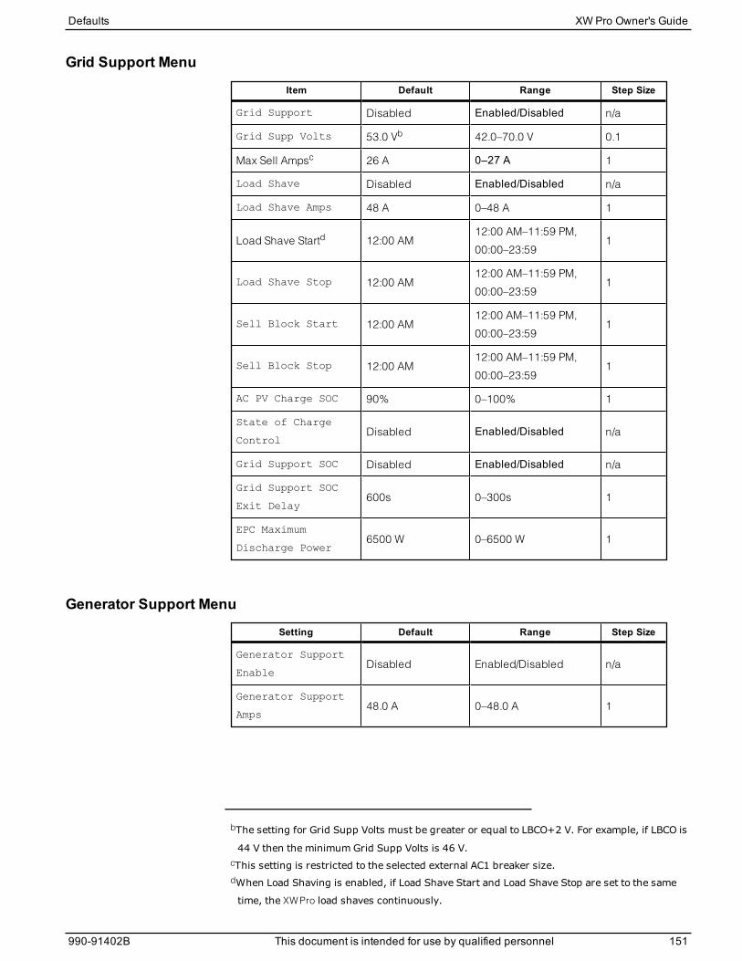
Grid Support Menu
Item Default Range Step Size
Grid Support Disabled Enabled/Disabled n/a
Grid Supp Volts 53.0 Vb 42.0–70.0 V 0.1
Max Sell Ampsc 26 A 0–27 A 1
Load Shave Disabled Enabled/Disabled n/a
Load Shave Amps 48 A 0–48 A 1
Load Shave Startd 12:00 AM12:00 AM–11:59 PM,
00:00–23:591
Load Shave Stop 12:00 AM12:00 AM–11:59 PM,
00:00–23:591
Sell Block Start 12:00 AM12:00 AM–11:59 PM,
00:00–23:591
Sell Block Stop 12:00 AM12:00 AM–11:59 PM,
00:00–23:591
AC PV Charge SOC 90% 0–100% 1
State of Charge
ControlDisabled Enabled/Disabled n/a
Grid Support SOC Disabled Enabled/Disabled n/a
Grid Support SOC
Exit Delay600s 0–300s 1
EPC Maximum
Discharge Power6500 W 0–6500 W 1
Generator Support Menu
Setting Default Range Step Size
Generator Support
EnableDisabled Enabled/Disabled n/a
Generator Support
Amps48.0 A 0–48.0 A 1
bThe setting for Grid Supp Volts must be greater or equal to LBCO+2 V. For example, if LBCO is
44 V then the minimum Grid Supp Volts is 46 V.cThis setting is restricted to the selected external AC1 breaker size.dWhen Load Shaving is enabled, if Load Shave Start and Load Shave Stop are set to the same
time, the XW Pro load shaves continuously.
Defaults XW Pro Owner's Guide
990-91402B This document is intended for use by qualified personnel 151
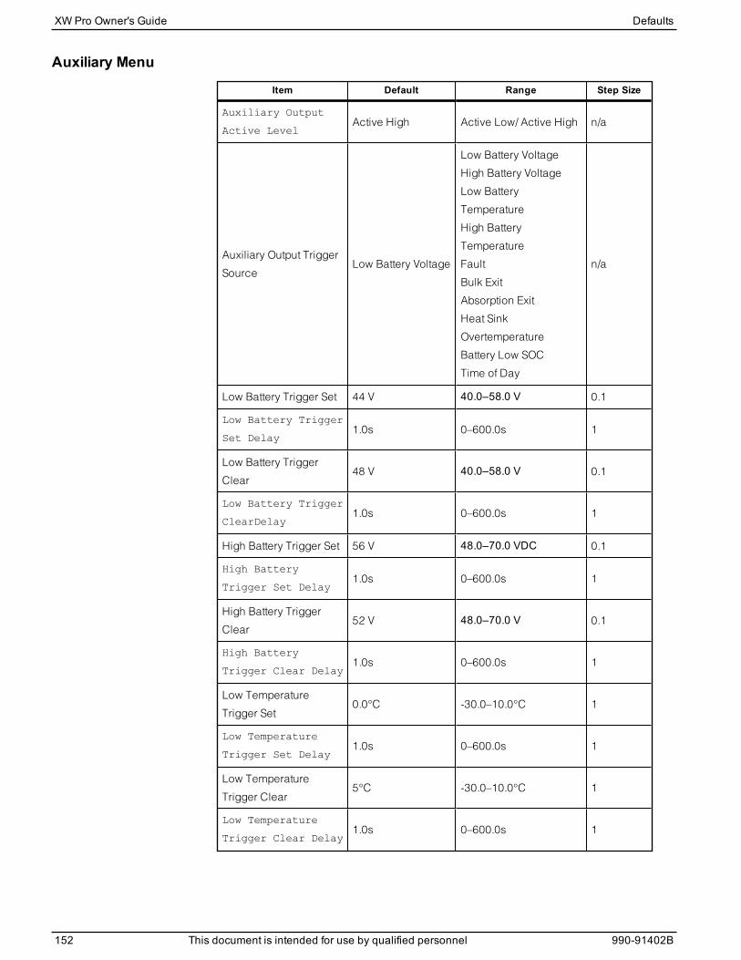
Auxiliary Menu
Item Default Range Step Size
Auxiliary Output
Active LevelActive High Active Low/ Active High n/a
Auxiliary Output Trigger
SourceLow Battery Voltage
Low Battery Voltage
High Battery Voltage
Low Battery
Temperature
High Battery
Temperature
Fault
Bulk Exit
Absorption Exit
Heat Sink
Overtemperature
Battery Low SOC
Time of Day
n/a
Low Battery Trigger Set 44 V 40.0–58.0 V 0.1
Low Battery Trigger
Set Delay1.0s 0–600.0s 1
Low Battery Trigger
Clear48 V 40.0–58.0 V 0.1
Low Battery Trigger
ClearDelay1.0s 0–600.0s 1
High Battery Trigger Set 56 V 48.0–70.0 VDC 0.1
High Battery
Trigger Set Delay1.0s 0–600.0s 1
High Battery Trigger
Clear52 V 48.0–70.0 V 0.1
High Battery
Trigger Clear Delay1.0s 0–600.0s 1
Low Temperature
Trigger Set0.0°C -30.0–10.0°C 1
Low Temperature
Trigger Set Delay1.0s 0–600.0s 1
Low Temperature
Trigger Clear5°C -30.0–10.0°C 1
Low Temperature
Trigger Clear Delay1.0s 0–600.0s 1
XW Pro Owner's Guide Defaults
152 This document is intended for use by qualified personnel 990-91402B
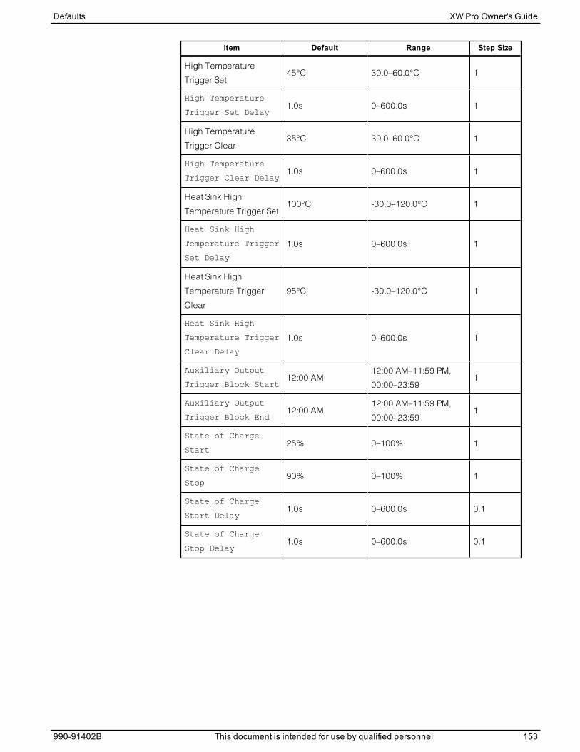
Item Default Range Step Size
High Temperature
Trigger Set45°C 30.0–60.0°C 1
High Temperature
Trigger Set Delay1.0s 0–600.0s 1
High Temperature
Trigger Clear35°C 30.0–60.0°C 1
High Temperature
Trigger Clear Delay1.0s 0–600.0s 1
Heat Sink High
Temperature Trigger Set100°C -30.0–120.0°C 1
Heat Sink High
Temperature Trigger
Set Delay
1.0s 0–600.0s 1
Heat Sink High
Temperature Trigger
Clear
95°C -30.0–120.0°C 1
Heat Sink High
Temperature Trigger
Clear Delay
1.0s 0–600.0s 1
Auxiliary Output
Trigger Block Start12:00 AM
12:00 AM–11:59 PM,
00:00–23:591
Auxiliary Output
Trigger Block End12:00 AM
12:00 AM–11:59 PM,
00:00–23:591
State of Charge
Start25% 0–100% 1
State of Charge
Stop90% 0–100% 1
State of Charge
Start Delay1.0s 0–600.0s 0.1
State of Charge
Stop Delay1.0s 0–600.0s 0.1
Defaults XW Pro Owner's Guide
990-91402B This document is intended for use by qualified personnel 153
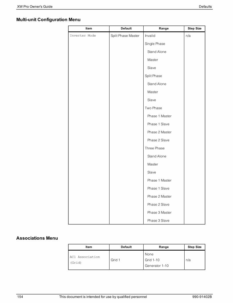
Multi-unit Configuration Menu
Item Default Range Step Size
Inverter Mode Split Phase Master Invalid
Single Phase
Stand Alone
Master
Slave
Split Phase
Stand Alone
Master
Slave
Two Phase
Phase 1 Master
Phase 1 Slave
Phase 2 Master
Phase 2 Slave
Three Phase
Stand Alone
Master
Slave
Phase 1 Master
Phase 1 Slave
Phase 2 Master
Phase 2 Slave
Phase 3 Master
Phase 3 Slave
n/a
Associations Menu
Item Default Range Step Size
AC1 Association
(Grid)Grid 1
None
Grid 1-10
Generator 1-10
n/a
XW Pro Owner's Guide Defaults
154 This document is intended for use by qualified personnel 990-91402B

Item Default Range Step Size
AC2 Association
(Generator)Generator 1
None
Generator 1-10
Grid 1-10
n/a
AC Output
Association (Loads)AC Load 1 AC Load 1-10 n/a
Battery AssociationHouse Battery Bank
1House Battery Bank 1-5 n/a
Advanced Features Menu
Item Default Range Step Size
Remote Power Off Disabled Enabled/Disabled n/a
Power Save Disabled Enabled/Disabled n/a
Sell Delay 40 sec Disabled Enabled/Disabled n/a
Generator Support
PlusDisabled Enabled/Disabled n/a
AC Coupling Enabled Enabled/Disabled n/a
Battery Energy
BalanceDisabled Enabled/Disabled n/a
Peak Load Shaving
DelayDisabled Enabled/Disabled n/a
External Transfer
ContactorDisabled Enabled/Disabled n/a
External Load
SwitchDisabled Enabled/Disabled n/a
For an explanation of these features, see "Advanced Features" on page 85.
Advanced Device Settings Menu
Item Default Range Step Size
Periodic Transmit
EnableEnabled Enabled/Disabled n/a
Identify Enable Disabled Enabled/Disabled n/a
Defaults XW Pro Owner's Guide
990-91402B This document is intended for use by qualified personnel 155
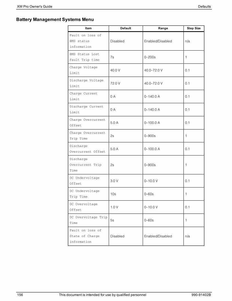
Battery Management Systems Menu
Item Default Range Step Size
Fault on loss of
BMS status
information
Disabled Enabled/Disabled n/a
BMS Status Lost
Fault Trip time7s 0–200s 1
Charge Voltage
Limit40.0 V 40.0–72.0 V 0.1
Discharge Voltage
Limit72.0 V 40.0–72.0 V 0.1
Charge Current
Limit0 A 0–140.0 A 0.1
Discharge Current
Limit0 A 0–140.0 A 0.1
Charge Overcurrent
Offset5.0 A 0–100.0 A 0.1
Charge Overcurrent
Trip Time2s 0–900s 1
Discharge
Overcurrent Offset5.0 A 0–100.0 A 0.1
Discharge
Overcurrent Trip
Time
2s 0–900s 1
DC Undervoltage
Offset3.0 V 0–10.0 V 0.1
DC Undervoltage
Trip Time10s 0–60s 1
DC Overvoltage
Offset1.0 V 0–10.0 V 0.1
DC Overvoltage Trip
Time5s 0–60s 1
Fault on loss of
State of Charge
information
Disabled Enabled/Disabled n/a
XW Pro Owner's Guide Defaults
156 This document is intended for use by qualified personnel 990-91402B
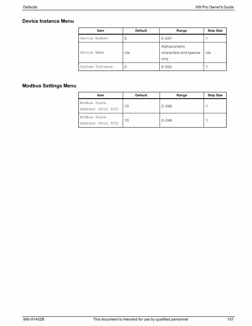
Device Instance Menu
Item Default Range Step Size
Device Number 0 0–247 1
Device Name n/a
Alphanumeric
characters and spaces
only
n/a
System Instance 0 0–255 1
Modbus Settings Menu
Item Default Range Step Size
Modbus Slave
Address (Port 502)10 2–246 1
Modbus Slave
Address (Port 503)10 2–246 1
Defaults XW Pro Owner's Guide
990-91402B This document is intended for use by qualified personnel 157

Schneider Electric
Asstandards, specifications, and designs change from time to time,
please ask for confirmation of the information given in this publication.
For other country details please contact your localSchneider Electric
SalesRepresentative or visit the Schneider ElectricSolar Business
website at: https://solar.schneider-electric.com
© 2021 Schneider Electric. All RightsReserved.
990-91402B Printed in: India
barcode