Embed Size (px)
Citation preview

Conet OPC Server CC026A
User’s Manual
Conet OPC Server 2 -© Omniflex UMCC026AR02.pdf
DATE REVISION COMMENTS 21st July 2004 1 Initial Issue 29th Aug 2006 2 Added support for M126x Queues
SOFTWARE COPY AVAILABLE This manual is available in printed form or in Adobe Acrobat pdf format. The pdf file is named UMCC026AR01.pdf
COPYRIGHT AND PROTECTIVE NOTICES 1. The Copyright of this document and the associated drawings, is the property of Omniflex and
is issued on condition that it is not copied, reprinted or reproduced or transmitted in any form or by any means, electronically, photocopying, mechanical or otherwise, nor its contents disclosed, either wholly or in part, without the consent in writing of, or in accordance with the conditions of a contract with Omniflex.
2. The publication of information in the document does not imply freedom from patent or other protective rights of Omniflex or others.
3. Although every intention is made to ensure that performance figures and data are accurate the company reserves the right to alter without notice any product or specification. Performance figures and data must therefore be specifically confirmed by the company before they become applicable to any tender, order or contract.
4. In the case of electrical components, enough data is included in the drawings to allow maintenance of the equipment. However, if component availability or substitution information is required please consult the factory for assistance, as it is impossible to include data on every component in this document.
5. This product is sold without liability for consequential loss of any description.
Conet OPC Server 3 -© Omniflex UMCC026AR02.pdf
SCOPE
This User Manual provides information on how to install, configure and use the Conet OPC Server. This manual covers the following product Models:
Model Description CC026A Conet OPC Server
Conet OPC Server 4 -© Omniflex UMCC026AR02.pdf
Table of Contents
1. GENERAL DESCRIPTION ....................................................................................................... 7 1.1 Conet OPC Server Configurator.................................................................................... 7 1.2 Conet OPC Server Runtime module ............................................................................. 7 1.3 Sample OPC Client ....................................................................................................... 7
2. OPC FUNDAMENTALS............................................................................................................ 8 2.1 Background ................................................................................................................... 8
2.1.1 The Problem..................................................................................................................... 8 2.1.2 The Solution ..................................................................................................................... 8
2.2 How the OPC Server works .......................................................................................... 9 3. INSTALLING THE Conet OPC Server.................................................................................... 10
3.1 System Requirements ................................................................................................. 10 3.2 Installing the Conet OPC Server ................................................................................. 10
3.2.1 Installing the Conet OPC Server software ..................................................................... 10 4. OPERATING THE CONET OPC SERVER ............................................................................ 11
4.1 Structure of the Conet OPC Server............................................................................. 11 4.1.1 The Configurator ............................................................................................................ 11 4.1.2 The “Active” Database ................................................................................................... 12 4.1.3 The Runtime Module...................................................................................................... 12 4.1.4 OPC Client ..................................................................................................................... 12 4.1.5 OPC Items...................................................................................................................... 12 4.1.6 OPC Groups................................................................................................................... 12 4.1.7 The OPC Test Client ...................................................................................................... 13
4.2 Configuring the Conet OPC Server ............................................................................. 13 4.2.1 File menu ....................................................................................................................... 13
4.2.1.1. New, Open, Save As…, Exit............................................................................. 13 4.2.1.2. Export CSV… ................................................................................................... 14 4.2.1.3. Import CSV… ................................................................................................... 14 4.2.1.4. Make Active… .................................................................................................. 14
4.2.2 Edit Menu ....................................................................................................................... 15 4.2.2.1. New................................................................................................................... 15 4.2.2.2. Rename, Delete, Cut, Copy, and Paste ........................................................... 15 4.2.2.3. Select All........................................................................................................... 15 4.2.2.4. Invert Selection................................................................................................. 15 4.2.2.5. Multiply ............................................................................................................. 15
4.2.3 View Menu ..................................................................................................................... 16 4.2.3.1. Toolbars............................................................................................................ 16
Conet OPC Server 5 -© Omniflex UMCC026AR02.pdf
4.2.3.2. Statusbar .......................................................................................................... 16 4.2.3.3. Large Icons, Small Icons, List, Details ............................................................. 16 4.2.3.4. Dialog View and Monitor View.......................................................................... 16 4.2.3.5. Select Language............................................................................................... 16 4.2.3.6. Show/Hide columns.......................................................................................... 16 4.2.3.7. Sort by .............................................................................................................. 16
4.2.4 Go Menu ........................................................................................................................ 16 4.2.5 Tools Menu .................................................................................................................... 16
4.2.5.1. Options ............................................................................................................. 16 4.2.5.2. Save regional settings in registry ..................................................................... 17 4.2.5.3. Automatically apply changes when selection changed .................................... 17 4.2.5.4. Enable hover selection ..................................................................................... 17 4.2.5.5. Update rate....................................................................................................... 17
4.2.6 Popup menus ................................................................................................................. 17 4.2.7 Creating OPC Items in the OPC Server......................................................................... 17
4.2.7.1. Address Space ................................................................................................. 17 4.2.7.2. Port ................................................................................................................... 18 4.2.7.3. Device............................................................................................................... 18 4.2.7.4. Data Item .......................................................................................................... 21 4.2.7.5. Folder................................................................................................................ 22
4.2.8 Using Simulation ............................................................................................................ 23 4.2.9 Using “Manual” Override................................................................................................ 23 4.2.10 Creating Device Parameters........................................................................................ 24 4.2.11 Creating Conversions................................................................................................... 24
4.2.11.1. Conversion Parameters.................................................................................... 25 4.2.11.2. Type of Conversion .......................................................................................... 25 4.2.11.3. Clamping .......................................................................................................... 25
4.2.12 Creating Simulation Signals......................................................................................... 26 4.2.13 Creating Alarm Definitions ........................................................................................... 27
4.2.13.1. Limit Alarms...................................................................................................... 27 4.2.13.2. Digital Alarms ................................................................................................... 29
4.2.14 Using a Maxilarm ......................................................................................................... 30 4.2.15 Using the SER 260....................................................................................................... 30 4.2.16 Using M126x with Queue support................................................................................ 31 4.2.17 Using the Configurator Monitor View ........................................................................... 32
4.3 Running the Conet OPC Server .................................................................................. 33 4.3.1 Determining if the server is running. .............................................................................. 33 4.3.2 Selecting the correct Database to use in the Runtime module...................................... 33
Conet OPC Server 6 -© Omniflex UMCC026AR02.pdf
5. RUNNING THE SAMPLE OPC CLIENT................................................................................. 34 5.1 Introduction.................................................................................................................. 34 5.2 Installing the Sample OPC Client ................................................................................ 34 5.3 Using the Sample OPC Client ..................................................................................... 34
5.3.1 Starting the Sample OPC............................................................................................... 34 5.3.2 To Connect the Sample Client to the Conet OPC Server.............................................. 34 5.3.3 Viewing the Status of the OPC Server........................................................................... 35 5.3.4 Adding Items to the Sample OPC Client........................................................................ 35 5.3.5 Changing OPC Group Parameters ................................................................................ 37 5.3.6 Running Multiple Sample Clients ................................................................................... 38 5.3.7 How Sample OPC Clients get data from the OPC Server ............................................. 38 5.3.8 Writing Data from the Client to the Server/Device in the field........................................ 38
Table of Figures
Figure 2.1 The OPC Client/Server Interface ................................................................................... 9 Figure 4.1 Structure of the OPC Server ........................................................................................ 11 Figure 4.2 Main Configurator Screen ............................................................................................ 13 Figure 4.3 Make Active Confirmation Dialogue box. ..................................................................... 14 Figure 4.4 Mulitply Item Dialogue Window.................................................................................... 15 Figure 4.5 Tools/Options Dialogue Window.................................................................................. 17 Figure 4.6 Main Window with Port named “NET1” selected ......................................................... 18 Figure 4.7 Main Window with Device “NODE2” selected.............................................................. 19 Figure 4.8 Main Window with Data Item “DIT23” selected............................................................ 21 Figure 4.9 Main Window showing use of Folders to group Data Items......................................... 23 Figure 4.10 Main Window showing the Device Parameters Dialogue box. .................................. 24 Figure 4.11 Main Window showing the Conversions dialogue box............................................... 25 Figure 4.12 Main Window showing the Simulation Signal Dialogue Box. ..................................... 26 Figure 4.13 Main Window showing a Limit Alarm Dialogue Box................................................... 28 Figure 4.14 Main Window showing a Digital Alarm Dialogue Box ................................................ 29 Figure 4.15 Main Window with Monitor View displayed ................................................................ 32 Figure 5.1 Selecting an OPC Server in the Sample OPC Client................................................... 34 Figure 5.2 Sample OPC Client Server Status Window ................................................................. 35 Figure 5.3 Sample Client Add Item Dialogue ................................................................................ 36 Figure 5.4 Sample OPC Client ...................................................................................................... 37
Conet OPC Server 7 -© Omniflex UMCC026AR02.pdf
1. GENERAL DESCRIPTION
The OMNIFLEX Conet OPC Server is an OPC compliant Server, able to communicate with devices on a Conet/c, Conet/e, Modbus RTU/ASCII, Modbus/TCP and Conet/s network, and serve data to OPC clients. The Conet OPC Server supports both the Data Access and Alarm and Event interfaces as defined in the OPC Specification. The Conet OPC Server is compatible with Microsoft Windows 98/NT/2000. The OPC Server is supplied with the following components:
1.1 Conet OPC Server Configurator This independent program is used to configure the Conet OPC Server for use, by specifying the connection to the network, and creating OPC Items for the OPC Clients to subscribe to.
1.2 Conet OPC Server Runtime module The Conet OPC Server Runtime module is the part of the software that runs whenever an OPC client requests a connection to the Conet OPC Server. The Runtime module reads a configuration database created by the Configurator upon start up.
1.3 Sample OPC Client A Sample OPC Client application is installed with the Conet OPC Server. This Sample OPC Client provides a quick and easy method to test the operation and configuration of your Conet OPC Server. The Sample OPC Client is able to display the complete list of installed OPC Servers, and to browse the Tag data configured in any of these servers. The Sample OPC Client is also useful for verifying the operation of other third party clients such as SCADA packages connected to the Server.
Conet OPC Server 8 -© Omniflex UMCC026AR02.pdf
2. OPC FUNDAMENTALS
2.1 Background 2.1.1 The Problem
Computers have become common place in the control of industrial processes in real time, executing MMI’s, SCADA, or SPC functions. The software on these computers needs to access plant data in real time to perform its tasks. This is done using Industrial I/O Systems. Before OPC, each software vendor would require a software “driver” to interface to the brand of I/O system selected for the job. In many cases, more than one brand of I/O is used, and the software must then support multiple drivers simultaneously. This led to the following problems: • Duplicated effort caused by each software vendor writing similar drivers. • Inconsistencies caused by each software vendor only implementing features they
each require from the I/O system. • Compatibility problems caused by upgrades to hardware or software product
specifications. • Access conflicts caused by the fact that only one software driver can access the
hardware at a time. I/O System Vendors would like to help by developing drivers, but face the problem of which drivers to develop.
2.1.2 The Solution OLE for Process Control (OPC®) is a software interface standard designed by industry, based upon Microsoft “OLE” technology. This interface standard draws a line inside the computer between hardware and software providers. The OPC specification defines the software interface that allows hardware developers to provide a single “driver” product that can be used by multiple software applications from different vendors (simultaneously if necessary). It places the burden of data collection and distribution on the shoulders of each hardware supplier. This makes more sense since they know the most accessing data from their own devices in the most efficient manner. Using the OPC standard, the hardware supplier now provides a single “OPC Server” for all applications, and the end user can readily combine hardware and software products together without fear of interoperability concerns. The OPC Server communicates with the I/O System, and makes the data available in the standard OPC format within the OPC Server. The client software accesses the real-time data through the OPC Server.
Conet OPC Server 9 -© Omniflex UMCC026AR02.pdf
...
OPC ServerB
OPC ServerA
OPC ServerC
ApplicationX
OPC Interface
ApplicationY
OPC Interface
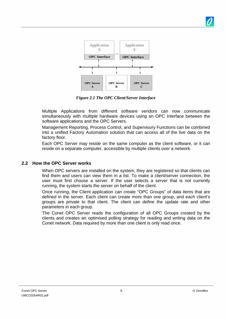
Figure 2.1 The OPC Client/Server Interface
Multiple Applications from different software vendors can now communicate simultaneously with multiple hardware devices using an OPC Interface between the software applications and the OPC Servers. Management Reporting, Process Control, and Supervisory Functions can be combined into a unified Factory Automation solution that can access all of the live data on the factory floor. Each OPC Server may reside on the same computer as the client software, or it can reside on a separate computer, accessible by multiple clients over a network.
2.2 How the OPC Server works When OPC servers are installed on the system, they are registered so that clients can find them and users can view them in a list. To make a client/server connection, the user must first choose a server. If the user selects a server that is not currently running, the system starts the server on behalf of the client. Once running, the Client application can create “OPC Groups” of data items that are defined in the server. Each client can create more than one group, and each client’s groups are private to that client. The client can define the update rate and other parameters in each group. The Conet OPC Server reads the configuration of all OPC Groups created by the clients and creates an optimised polling strategy for reading and writing data on the Conet network. Data required by more than one client is only read once.
Conet OPC Server 10 -© Omniflex UMCC026AR02.pdf
3. INSTALLING THE Conet OPC Server
3.1 System Requirements The following are system requirements for installing The Conet OPC Server and OPC test Client applications: Windows 2000, Windows NT 4.0 or Windows 9x with the latest version of DCOM is required to use the CONET local server. Hardware requirements: • Pentium 166 • 32 MB RAM • 50 MB Hard disk • Internet Explorer 4.0 or greater installed. Note: If you have Internet Explorer 4.0 installed, or wish to install it, you should read the installation notes for IE4.0, since DCOM is part of IE4.0 and an old version of DCOM may be installed.
3.2 Installing the Conet OPC Server 3.2.1 Installing the Conet OPC Server software
Follow this procedure to install the Conet OPC Server: 1. Insert the Conet OPC Server CD in the drive. 2. In Windows NT 4.0, Windows 9x or Windows 2000, click Start, and choose Run. 3. In the Run dialog box, type the following:
D:/Setup (replacing “D” with the actual location of your CD drive)
4. Follow the instructions provided by the Installation software.
Conet OPC Server 11 -© Omniflex UMCC026AR02.pdf
4. OPERATING THE CONET OPC SERVER
4.1 Structure of the Conet OPC Server
DIT
0
65535
SelectedItems
NODE01Node 1
DIT
0
65535
Node 'nn'
DIT
0
65535
Node 2Model C6193Conet/PCI Card
SelectedItems
NODE02
SelectedItems
NODEnn
Virtual Link
Virtual Link
Virtual Link
CONETNETWOR
OPCGroup 1(created
by client A)
OPCGroup 2
(created byclient A)
Conet.mdb
Read atStartup
Conet OPC Server Runtime Module
OPCGroup 1
(created byclient B)
OPCGroup 2
(created byclient B)
OPC CLIENT A
OPC CLIENT B
ConfiguratorConet OPC Server
Configurator
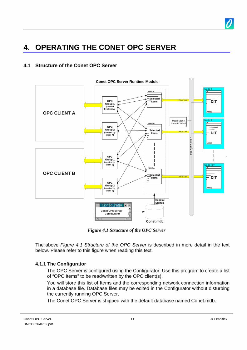
Figure 4.1 Structure of the OPC Server
The above Figure 4.1 Structure of the OPC Server is described in more detail in the text below. Please refer to this figure when reading this text. 4.1.1 The Configurator
The OPC Server is configured using the Configurator. Use this program to create a list of “OPC Items” to be read/written by the OPC client(s). You will store this list of Items and the corresponding network connection information in a database file. Database files may be edited in the Configurator without disturbing the currently running OPC Server. The Conet OPC Server is shipped with the default database named Conet.mdb.
Conet OPC Server 12 -© Omniflex UMCC026AR02.pdf
4.1.2 The “Active” Database You can create more than one database using the Configurator, as long as you store them with different file names. You will set one database file from the Configurator as being the “Active” database. This is the database that the OPC Server Runtime Module will read when it starts up to determine the Data Items to be polled from the nodes on the Conet network. Once started, the Conet OPC Server Runtime module ignores any changes made to this database until the next time it is stopped and started. This allows editing of the database to occur without upsetting the running Conet OPC Server.
4.1.3 The Runtime Module The Runtime module reads the “Active” database upon start up, and builds a list of data Items to be available for polling. These items are only polled if requested by an OPC Client, by placing these Items in an OPC Group created by the Client in the OPC Server.
4.1.4 OPC Client An “OPC Client” is a third party software program that can access data in the OPC Server. More than one OPC Client can access data from an OPC Server at the same time, (and generally OPC Clients can access data from more than one OPC Server at the same time). For information on the specific features and configuration of your selected OPC Client, see the documentation for that product.
4.1.5 OPC Items You will create OPC Items using the Configurator. The OPC Items are created in a structured hierarchy based upon the source/destination node of the Item on the Conet network.
4.1.6 OPC Groups Each OPC Client creates one or more OPC Groups in the OPC Server, and selects OPC Items from the list of Items defined in the RunTime module’s Active Database to be placed in each OPC Group. These Groups are normally defined when the OPC Client is configured. See your OPC Client documentation for more information on this. Each OPC Group has its poll rate (and other parameters) set by the OPC client. Each OPC Group is created by, and can be seen by only one OPC client. The OPC Items contained in each OPC Group, as created by the OPC Client, can be selected from any of the existing Items in the Runtime module’s database. The selection of items in each OPC Group will be related to how the OPC Client wishes to view the data, and is not related to the hierarchical structure of the OPC Items as created using the Configurator. The Conet OPC Server will resolve the seemingly random selection of Items in each OPC Group into an optimised polling schedule, and will poll the data on the network to provide this real time data as required from time to time by all active OPC Clients.
Conet OPC Server 13 -© Omniflex UMCC026AR02.pdf
4.1.7 The OPC Test Client The Conet OPC Server ships with an OPC Test Client that can be used to test/verify the OPC Server prior to deployment using a third party OPC Client such as a SCADA package.
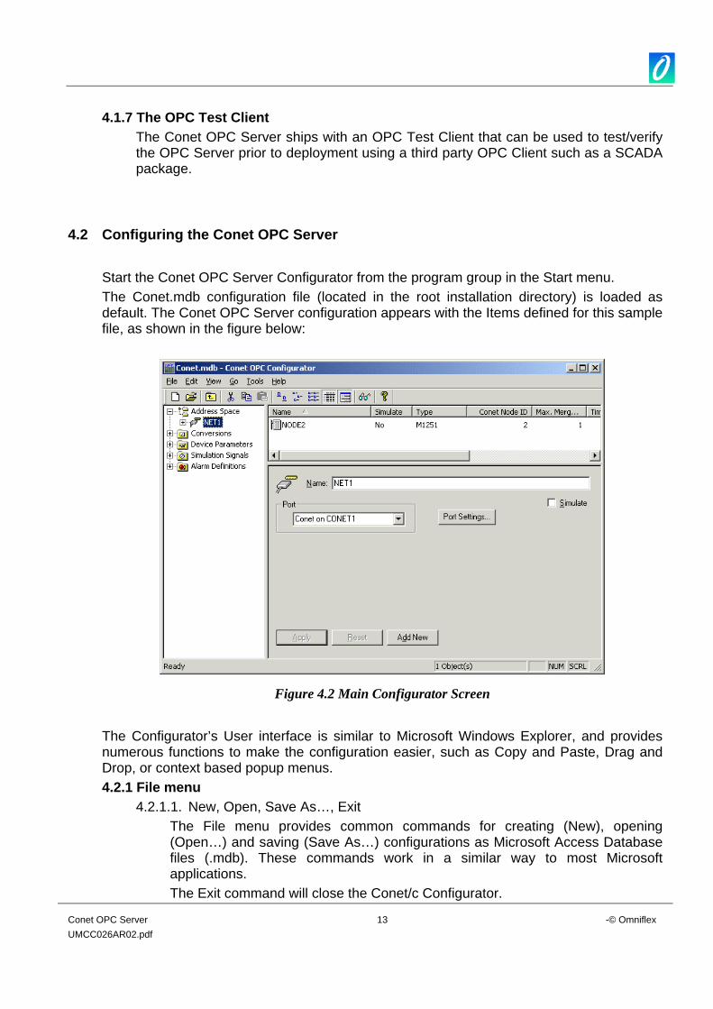
4.2 Configuring the Conet OPC Server Start the Conet OPC Server Configurator from the program group in the Start menu. The Conet.mdb configuration file (located in the root installation directory) is loaded as default. The Conet OPC Server configuration appears with the Items defined for this sample file, as shown in the figure below:
Figure 4.2 Main Configurator Screen
The Configurator’s User interface is similar to Microsoft Windows Explorer, and provides numerous functions to make the configuration easier, such as Copy and Paste, Drag and Drop, or context based popup menus. 4.2.1 File menu
4.2.1.1. New, Open, Save As…, Exit The File menu provides common commands for creating (New), opening (Open…) and saving (Save As…) configurations as Microsoft Access Database files (.mdb). These commands work in a similar way to most Microsoft applications. The Exit command will close the Conet/c Configurator.
Conet OPC Server 14 -© Omniflex UMCC026AR02.pdf
4.2.1.2. Export CSV…
Commands in this submenu allow exporting different parts of the configuration into a standard CSV (comma separated variables) file.
4.2.1.3. Import CSV… Commands in this submenu allow importing different parts of the configuration from a standard CSV (comma separated variable) file. These Export and Import CSV commands can be used to transfer sections of configuration between databases.
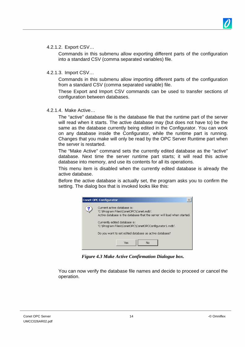
4.2.1.4. Make Active… The “active” database file is the database file that the runtime part of the server will read when it starts. The active database may (but does not have to) be the same as the database currently being edited in the Configurator. You can work on any database inside the Configurator, while the runtime part is running. Changes that you make will only be read by the OPC Server Runtime part when the server is restarted. The “Make Active” command sets the currently edited database as the “active” database. Next time the server runtime part starts; it will read this active database into memory, and use its contents for all its operations. This menu item is disabled when the currently edited database is already the active database. Before the active database is actually set, the program asks you to confirm the setting. The dialog box that is invoked looks like this:
Figure 4.3 Make Active Confirmation Dialogue box.
You can now verify the database file names and decide to proceed or cancel the operation.
Conet OPC Server 15 -© Omniflex UMCC026AR02.pdf
4.2.2 Edit Menu 4.2.2.1. New
This submenu contains commands to add new objects into an active branch in the tree. The actual contents of this submenu changes based on the type of the branch you have selected in the left hand tree view pane.
4.2.2.2. Rename, Delete, Cut, Copy, and Paste This menu contains the common Rename, Delete, Cut, Copy, and Paste commands. The Configurator also supports standard “drag and drop” behaviour in most List and Tree views.
4.2.2.3. Select All Select All is used to select all items in a List View. In many cases, more than one item may be selected using the “Ctrl” key to add individual items to the selection, or using the “Shift” key to select a range of items.
4.2.2.4. Invert Selection The “Invert Selection” command is used to deselect those items currently selected, and select those items not currently selected.
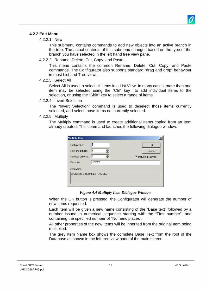
4.2.2.5. Multiply The Multiply command is used to create additional Items copied from an Item already created. This command launches the following dialogue window:
Figure 4.4 Mulitply Item Dialogue Window
When the OK button is pressed, the Configurator will generate the number of new items requested. Each item will be given a new name consisting of the “Base text” followed by a number issued in numerical sequence starting with the “First number”, and containing the specified number of “Numeric places”. All other properties of the new Items will be inherited from the original Item being mulitplied. The grey Item Name box shows the complete Base Text from the root of the Database as shown in the left tree view pane of the main screen.

Conet OPC Server 16 -© Omniflex UMCC026AR02.pdf
4.2.3 View Menu 4.2.3.1. Toolbars
Show/hide the “Standard Buttons” and “Data Manipulation Buttons” toolbars from this submenu.
4.2.3.2. Statusbar Show/hide the Status bar, along the bottom of the main window, using this submenu.
4.2.3.3. Large Icons, Small Icons, List, Details Use this selection to display the items in the right pane in the selected mode.
4.2.3.4. Dialog View and Monitor View Show/hide the relevant views using the appropriate menu item. Alternatively press F11 to toggle the Dialog View on/off or F12 to toggle the Monitor View pane on/off. Both Dialog and Monitor View are described further below.
4.2.3.5. Select Language Use this menu item to adjust the international environment setting for the software.
4.2.3.6. Show/Hide columns The right hand list pane, when in Details view, has a wide variety of display options. Use “Show/Hide columns” menu item to select which parameters to view.
4.2.3.7. Sort by Use this menu item to sort the Right Hand pane by the selected parameter. Alternatively, in the Details view, click on the Column heading to sort by that column. Clicking the column heading a second time will sort the column in the opposite order.
4.2.4 Go Menu
To view available records in whatever window is selected, use a command from the list that appears in the Go menu, or use the Arrow, Page Up/Down, Home, End keys for moving in the tree view in combination with Alt key. The “Up One Level” command moves the cursor one level closer to the root of the tree. “Next Pane” or “Previous Pane” allows you to switch through panes, if more than one is displayed.
4.2.5 Tools Menu 4.2.5.1. Options
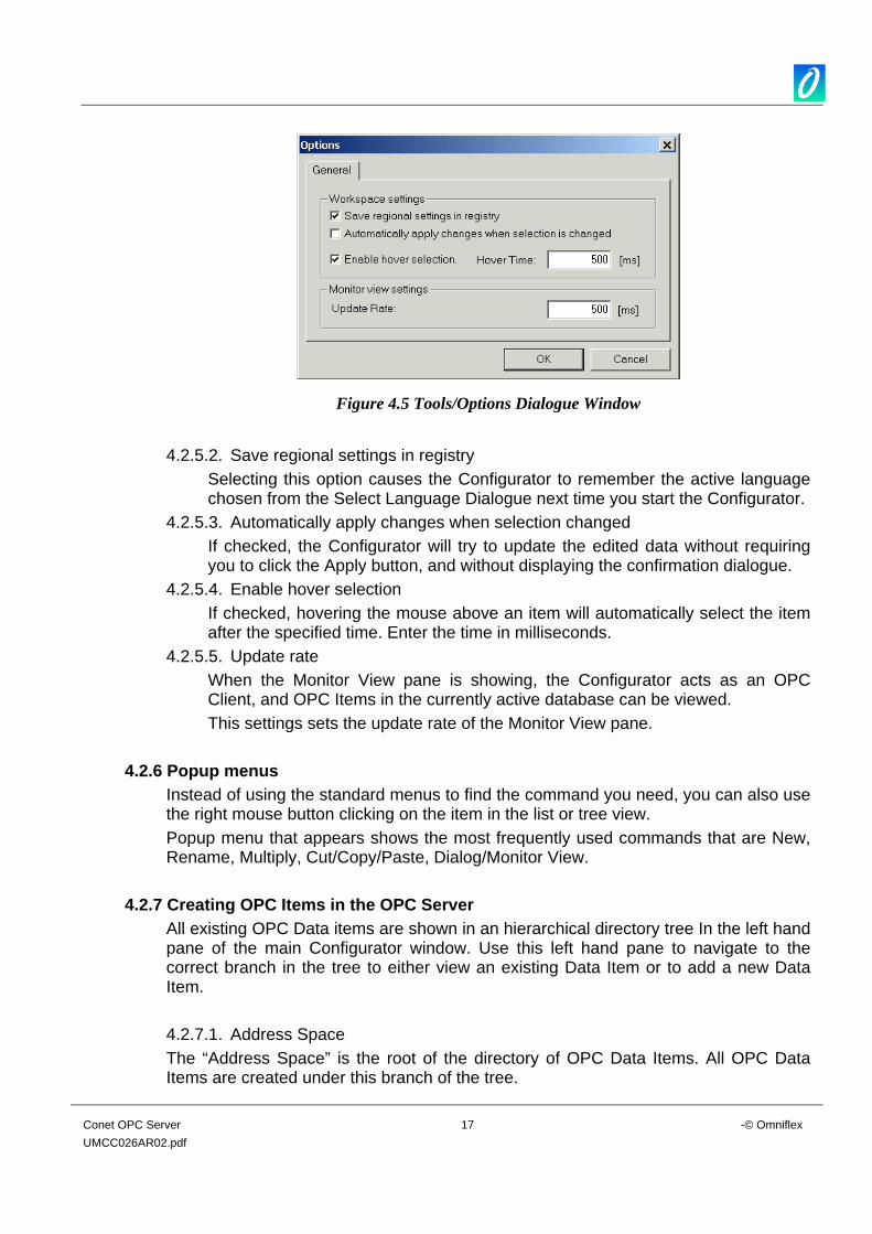
The Options dialog selected from the Tools menu contains Workspace parameters.
Conet OPC Server 17 -© Omniflex UMCC026AR02.pdf
Figure 4.5 Tools/Options Dialogue Window
4.2.5.2. Save regional settings in registry
Selecting this option causes the Configurator to remember the active language chosen from the Select Language Dialogue next time you start the Configurator.
4.2.5.3. Automatically apply changes when selection changed If checked, the Configurator will try to update the edited data without requiring you to click the Apply button, and without displaying the confirmation dialogue.
4.2.5.4. Enable hover selection If checked, hovering the mouse above an item will automatically select the item after the specified time. Enter the time in milliseconds.
4.2.5.5. Update rate When the Monitor View pane is showing, the Configurator acts as an OPC Client, and OPC Items in the currently active database can be viewed. This settings sets the update rate of the Monitor View pane.
4.2.6 Popup menus
Instead of using the standard menus to find the command you need, you can also use the right mouse button clicking on the item in the list or tree view. Popup menu that appears shows the most frequently used commands that are New, Rename, Multiply, Cut/Copy/Paste, Dialog/Monitor View.
4.2.7 Creating OPC Items in the OPC Server All existing OPC Data items are shown in an hierarchical directory tree In the left hand pane of the main Configurator window. Use this left hand pane to navigate to the correct branch in the tree to either view an existing Data Item or to add a new Data Item. 4.2.7.1. Address Space The “Address Space” is the root of the directory of OPC Data Items. All OPC Data Items are created under this branch of the tree.
Conet OPC Server 18 -© Omniflex UMCC026AR02.pdf
There is no configuration required at this level. 4.2.7.2. Port
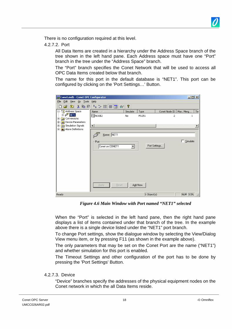
All Data Items are created in a hierarchy under the Address Space branch of the tree shown in the left hand pane. Each Address space must have one “Port” branch in the tree under the “Address Space” branch. The “Port” branch specifies the Conet Network that will be used to access all OPC Data Items created below that branch. The name for this port in the default database is “NET1”. This port can be configured by clicking on the 'Port Settings…' Button.
Figure 4.6 Main Window with Port named “NET1” selected
When the “Port” is selected in the left hand pane, then the right hand pane displays a list of items contained under that branch of the tree. In the example above there is a single device listed under the “NET1” port branch. To change Port settings, show the dialogue window by selecting the View/Dialog View menu item, or by pressing F11 (as shown in the example above). The only parameters that may be set on the Conet Port are the name (“NET1”) and whether simulation for this port is enabled. The Timeout Settings and other configuration of the port has to be done by pressing the 'Port Settings' Button.
4.2.7.3. Device “Device” branches specify the addresses of the physical equipment nodes on the Conet network in which the all Data Items reside.
Conet OPC Server 19 -© Omniflex UMCC026AR02.pdf
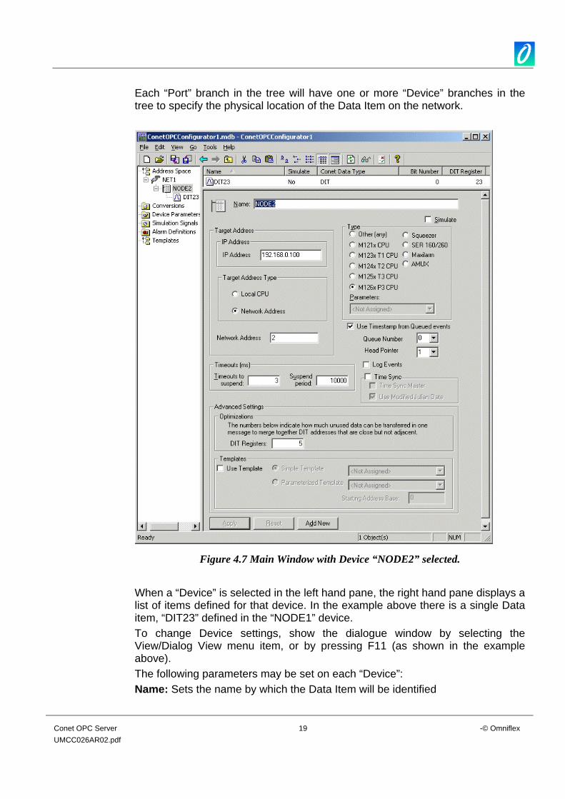
Each “Port” branch in the tree will have one or more “Device” branches in the tree to specify the physical location of the Data Item on the network.
Figure 4.7 Main Window with Device “NODE2” selected.
When a “Device” is selected in the left hand pane, the right hand pane displays a list of items defined for that device. In the example above there is a single Data item, “DIT23” defined in the “NODE1” device. To change Device settings, show the dialogue window by selecting the View/Dialog View menu item, or by pressing F11 (as shown in the example above). The following parameters may be set on each “Device”: Name: Sets the name by which the Data Item will be identified
Conet OPC Server 20 -© Omniflex UMCC026AR02.pdf
IP Address: Specifies the IP Address of the Node. This field will only be used if a Ethernet protocol is selected. Target Address Type: Specifies whether the device address is of type 'Local CPU' or whether the device has a network address. Network Address: Specifies the Conet Network Address as set on the Conet Address switch of the OMNIFLEX Hardware device. Simulate: enables/disables simulation for the device and all of its Data Items. Node Type: Specifies the type of node being connected to Selecting the node type automatically presets a number of other parameters required when polling the device. There a number of predefined node types shown on this dialogue. If your device is not specified amongst this list, then select “Other” and then select one of the Device Parameter groups listed in the pull-down box. If none of these fits your requirement, then additional Device Parameter Groups may be built in the Device Parameter tree selection in the left hand pane. Use timestamp from queued events: Certain M126x Cpu’s support queued timestamp events. Contact your Omniflex Agent to verify whether the device you have supports queued events. If you are not sure then disable this option. Use modified julian date: Certain M126x Cpu’s support the modified julian time format. Contact your Omniflex Agent to verify whether the device you uses modified julian date. This option is used for time syncing. If you are unsure then disable this option. Queue Number: This option is only used if the ‘Use timestamp from queued events’ is enabled. The default value is 0. Head Number: This option is only used if the ‘Use timestamp from queued events’ is enabled. The default value is 0. Log Events: If enabled it will log events to a text file called OPCLog.txt. This file can be found in the windows system32 directory. Time Sync: Enable the time sync check box if you wish to synchronise the time of the devices on your network. If ‘Time Sync Master’ is not checked then the pc uses it’s time to set the device’s time. If ‘Time Sync Master’ is checked then the pc sets it’s time according to the device’s time. Disabling time sync master is the preferred option. Timeouts to Suspend: specifies how many retry attempts the OPC Server should endure before suspending polling of this device. Suspend Period: specified how long the device should remain suspended before the OPC Server attempts to poll the device again. Optimisations: The server tries to optimise communication with the devices by requesting as much data as possible in one message. Consecutive registers are merged together into one request for efficiency. The server can also read registers that are not really required, if this allows it to join two blocks of requested registers into a single block for efficiency. The Word value entered under here specifies the number of unwanted registers that will be included in the poll to optimise the transaction.
Conet OPC Server 21 -© Omniflex UMCC026AR02.pdf
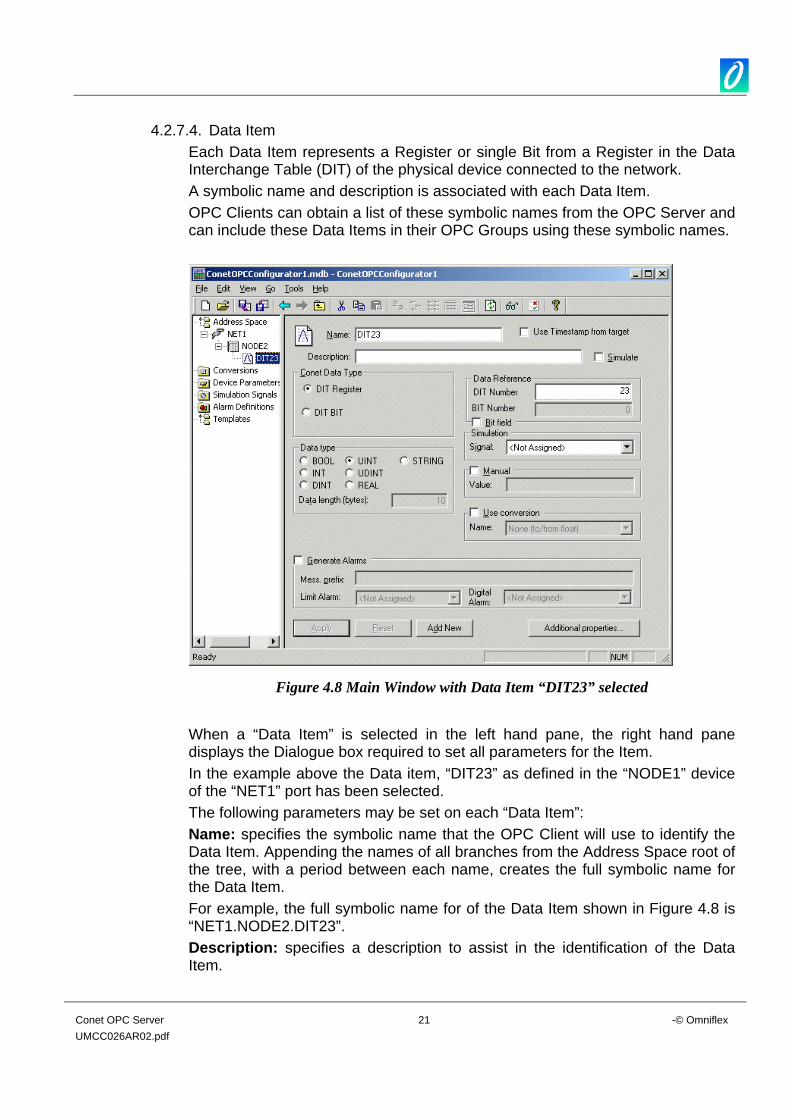
4.2.7.4. Data Item Each Data Item represents a Register or single Bit from a Register in the Data Interchange Table (DIT) of the physical device connected to the network. A symbolic name and description is associated with each Data Item. OPC Clients can obtain a list of these symbolic names from the OPC Server and can include these Data Items in their OPC Groups using these symbolic names.
Figure 4.8 Main Window with Data Item “DIT23” selected
When a “Data Item” is selected in the left hand pane, the right hand pane displays the Dialogue box required to set all parameters for the Item. In the example above the Data item, “DIT23” as defined in the “NODE1” device of the “NET1” port has been selected. The following parameters may be set on each “Data Item”: Name: specifies the symbolic name that the OPC Client will use to identify the Data Item. Appending the names of all branches from the Address Space root of the tree, with a period between each name, creates the full symbolic name for the Data Item. For example, the full symbolic name for of the Data Item shown in Figure 4.8 is “NET1.NODE2.DIT23”. Description: specifies a description to assist in the identification of the Data Item.
Conet OPC Server 22 -© Omniflex UMCC026AR02.pdf
Simulate: enables/disables simulation for the Data Item. Conet Data Type: specifies whether the Data Item refers to an entire 16 Register in the Data Interchange Table, or only a Bit from the register. DIT Number: specifies the address of the DIT Register in the Data Interchange Table being accessed. Theoretical Addresses can theoretically range from 0 to 65535, but no physical device contains this full range. Bit Number: specified the Bit in the register referred to by this Data Item if the Conet Data Type is specified as a Bit. Bit numbers range from 0 to 15, with bit 0 being the least significant (right most) bit. Simulation Signal: specifies the type of simulation signal to be used when simulation for this Data Item is enabled. This simulation signal is selected from the pull-down list of Simulation Signals. Manual: when checked, forces the Data Item value to that specified in the Value text box. Value: specifies the fixed value that the Data Item will be set to, when the Manual checkbox is checked. Generate Alarms: specifies whether this Data Item will generate alarms within the server. These alarms are available through the Alarm and Event interface of the OPC Server. Only OPC Clients equipped with this OPC “Alarm and Event” interface can take advantage of these server generated alarms. Message Prefix: specifies the text that will prefix the alarm when it occurs. The prefix will be followed by the text configured for a particular alarm type. The second part of the alarm message will contain the Message Body text string (see Alarm Definitions below). Limit Alarm: selects the Alarm Definition to be used for this alarm as defined in the Alarm Definitions. The Limit Alarm is only applicable to analogue values as specified by the selection of the DIT Register Conet Data Type. Digital Alarm: selects the Alarm Definition to be used for this alarm as defined in the Alarm Definitions. The Digital Alarm is only applicable to binary values as specified by the selection of the bit field checkbox. Use Conversion: is selected to get the data value converted according to a prescribed formula. Choose one of the predefined or user-defined conversion formulae from the pull-down list. See section on Conversions for more details.
4.2.7.5. Folder A Folder is an object added to the tree that can be used to group data items that logically belong together. It does not have any direct representation in the Conet protocol. You can use folders any way that is suitable to your application. Three levels of folders are supported in the Conet OPC Server.
Conet OPC Server 23 -© Omniflex UMCC026AR02.pdf
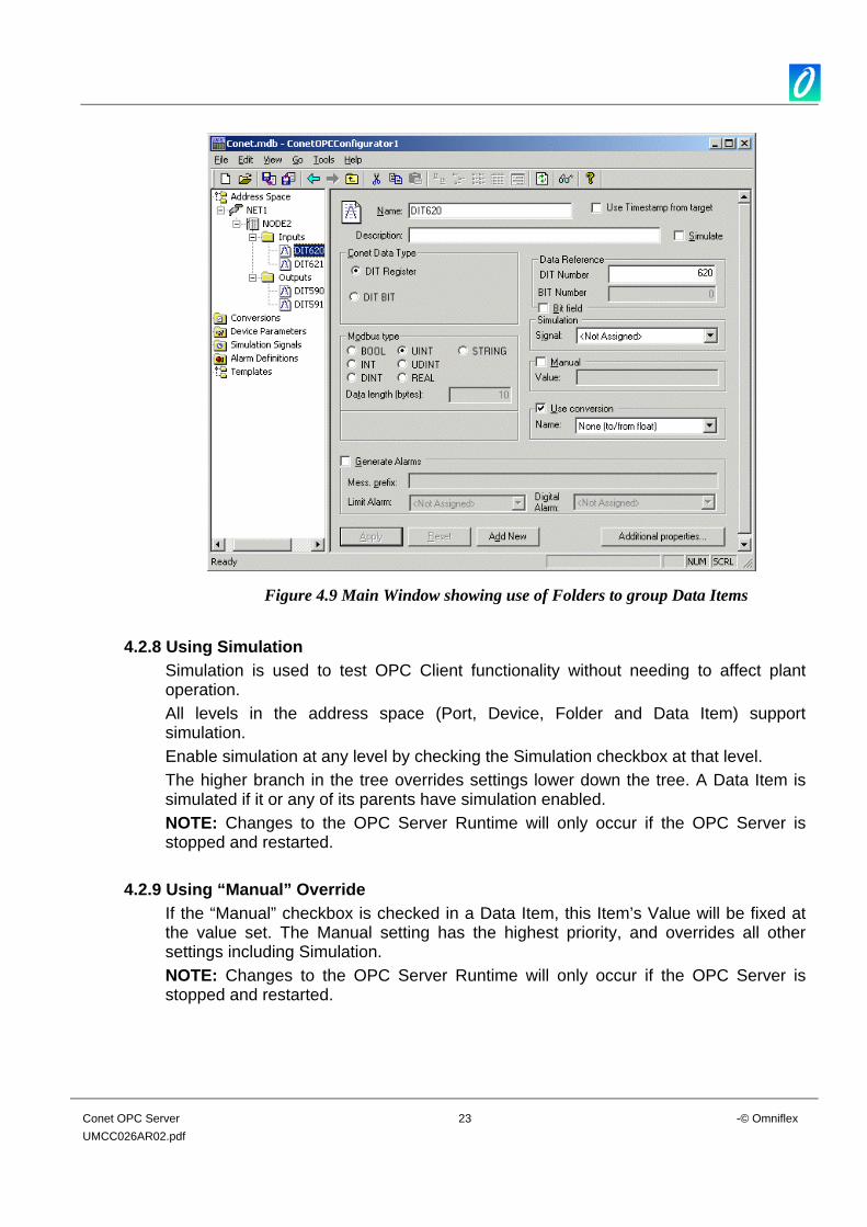
Figure 4.9 Main Window showing use of Folders to group Data Items
4.2.8 Using Simulation
Simulation is used to test OPC Client functionality without needing to affect plant operation. All levels in the address space (Port, Device, Folder and Data Item) support simulation. Enable simulation at any level by checking the Simulation checkbox at that level. The higher branch in the tree overrides settings lower down the tree. A Data Item is simulated if it or any of its parents have simulation enabled. NOTE: Changes to the OPC Server Runtime will only occur if the OPC Server is stopped and restarted.
4.2.9 Using “Manual” Override If the “Manual” checkbox is checked in a Data Item, this Item’s Value will be fixed at the value set. The Manual setting has the highest priority, and overrides all other settings including Simulation. NOTE: Changes to the OPC Server Runtime will only occur if the OPC Server is stopped and restarted.

Conet OPC Server 24 -© Omniflex UMCC026AR02.pdf
4.2.10 Creating Device Parameters The Device Parameters directory in the left hand pane contains the list of custom device types. Device parameters influence the behaviour and performance of the server for the device. The settings in the device parameters dialog specify the maximum amount of data that can be transferred in one message. Setting the value equal to zero means force the server to use single read/write messages only. Each Data Item created must have a Device Parameter selected. See Section 4.2.7.4 To create a new Device Parameter, select the Device Parameters directory in the tree in the left hand pane. Then right click and select New/Device Parameter from the submenu, or simply press Ctrl-P. The Device Parameters dialogue box for the new Device Parameter will display in the right hand pane.
Figure 4.10 Main Window showing the Device Parameters Dialogue box.
Set the maximum number of registers to be read or written from the device in the Read and Write boxes respectively.
4.2.11 Creating Conversions The Conversions feature allows you to tell the server to convert Item data into a form more suitable to the OPC Client. The Conversions directory in the left hand pane contains the list of custom Conversions configured in the Conet OPC Server. Each Data Item created can implement one of the Conversions in the Conversions directory.
Conet OPC Server 25 -© Omniflex UMCC026AR02.pdf
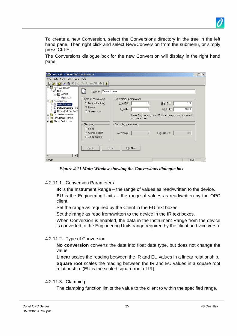
To create a new Conversion, select the Conversions directory in the tree in the left hand pane. Then right click and select New/Conversion from the submenu, or simply press Ctrl-E. The Conversions dialogue box for the new Conversion will display in the right hand pane.
Figure 4.11 Main Window showing the Conversions dialogue box
4.2.11.1. Conversion Parameters
IR is the Instrument Range – the range of values as read/written to the device. EU is the Engineering Units – the range of values as read/written by the OPC client. Set the range as required by the Client in the EU text boxes. Set the range as read from/written to the device in the IR text boxes. When Conversion is enabled, the data in the Instrument Range from the device is converted to the Engineering Units range required by the client and vice versa.
4.2.11.2. Type of Conversion No conversion converts the data into float data type, but does not change the value. Linear scales the reading between the IR and EU values in a linear relationship. Square root scales the reading between the IR and EU values in a square root relationship. (EU is the scaled square root of IR)
4.2.11.3. Clamping The clamping function limits the value to the client to within the specified range.
Conet OPC Server 26 -© Omniflex UMCC026AR02.pdf
Clamping can be disabled (None), set to clamp on the values as specified for the EU Range in the “Conversion Parameters” box (Clamp on EU) or set to clamp on other specified values (As specified) The definition of range limits using this clamping feature helps some client applications when the data goes out of range. If clamping is enabled, the data value will be limited to its High clamp/EU value, when it exceeds the upper limit, and similarly with Low clamp parameter.
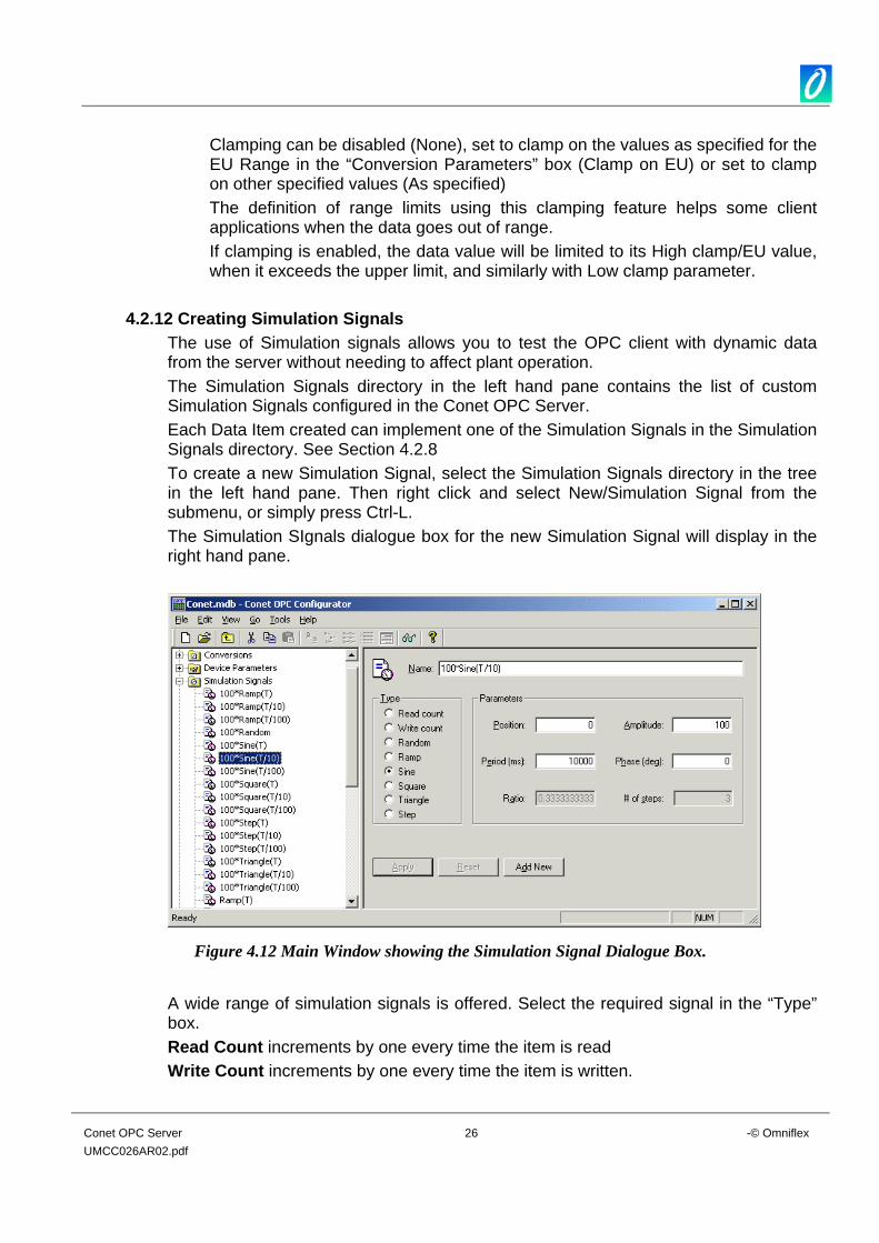
4.2.12 Creating Simulation Signals The use of Simulation signals allows you to test the OPC client with dynamic data from the server without needing to affect plant operation. The Simulation Signals directory in the left hand pane contains the list of custom Simulation Signals configured in the Conet OPC Server. Each Data Item created can implement one of the Simulation Signals in the Simulation Signals directory. See Section 4.2.8To create a new Simulation Signal, select the Simulation Signals directory in the tree in the left hand pane. Then right click and select New/Simulation Signal from the submenu, or simply press Ctrl-L. The Simulation SIgnals dialogue box for the new Simulation Signal will display in the right hand pane.
Figure 4.12 Main Window showing the Simulation Signal Dialogue Box.
A wide range of simulation signals is offered. Select the required signal in the “Type” box. Read Count increments by one every time the item is read Write Count increments by one every time the item is written.
Conet OPC Server 27 -© Omniflex UMCC026AR02.pdf
Random generates random values within the “Amplitude” range starting from “Position”. Ramp, Sine, Square, Triangle and Step are periodic signals. Their time behaviour is influenced by the “Period” and “Phase” parameters. “Period” specifies the signal frequency, while “Phase” moves the signal origin on the time axis. For the “Square” and “Triangle” signal “Ratio” defines the symmetry of the signal. A value of 0.5 defines a symmetrically shaped signal. Values lower than 0.5 reduce the rise/high time of the signal. “# of Steps” parameter of the “Step” signal defines the number of steps the signal amplitude will be divided into.
4.2.13 Creating Alarm Definitions Alarm Definitions are used to create specific types of alarms to be generated by the server. The Alarm Definitions directory in the left hand pane contains the list of custom Alarm Definitions configured in the Conet OPC Server. Each Data Item created can implement one of the Alarm Definitions in the Alarm Definitions directory according to its type. There are two types of Alarm Definitions: 4.2.13.1. Limit Alarms
Limit Alarms are generated by the server when an analogue value passes a preset setpoint or limit value. Limit Alarms can be applied to DIT Register Data Items only. To create a new Limit Alarm Definition, select the Alarm Definitions directory in the tree in the left hand pane. Then right click and select New/Limit Alarm Definition from the submenu or simply press Ctrl-H. The Alarm Definitions dialogue box for the new Limit Alarm Definition will display in the right hand pane.
Conet OPC Server 28 -© Omniflex UMCC026AR02.pdf
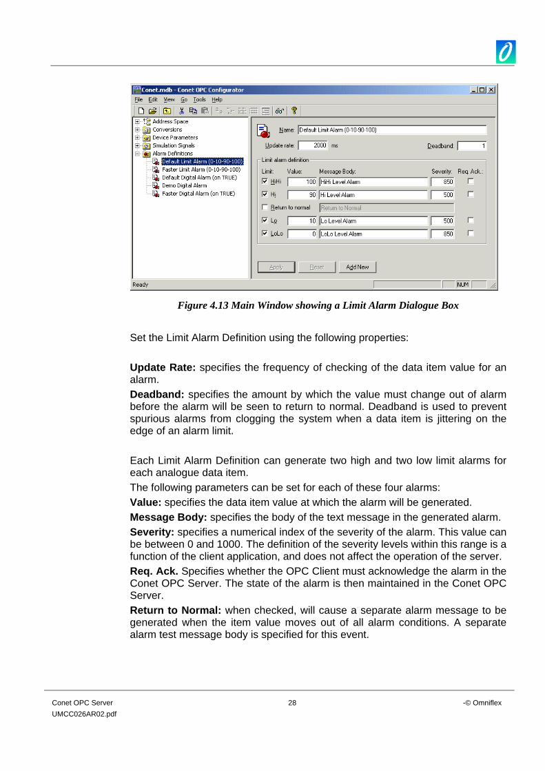
Figure 4.13 Main Window showing a Limit Alarm Dialogue Box
Set the Limit Alarm Definition using the following properties: Update Rate: specifies the frequency of checking of the data item value for an alarm. Deadband: specifies the amount by which the value must change out of alarm before the alarm will be seen to return to normal. Deadband is used to prevent spurious alarms from clogging the system when a data item is jittering on the edge of an alarm limit. Each Limit Alarm Definition can generate two high and two low limit alarms for each analogue data item. The following parameters can be set for each of these four alarms: Value: specifies the data item value at which the alarm will be generated. Message Body: specifies the body of the text message in the generated alarm. Severity: specifies a numerical index of the severity of the alarm. This value can be between 0 and 1000. The definition of the severity levels within this range is a function of the client application, and does not affect the operation of the server. Req. Ack. Specifies whether the OPC Client must acknowledge the alarm in the Conet OPC Server. The state of the alarm is then maintained in the Conet OPC Server. Return to Normal: when checked, will cause a separate alarm message to be generated when the item value moves out of all alarm conditions. A separate alarm test message body is specified for this event.
Conet OPC Server 29 -© Omniflex UMCC026AR02.pdf
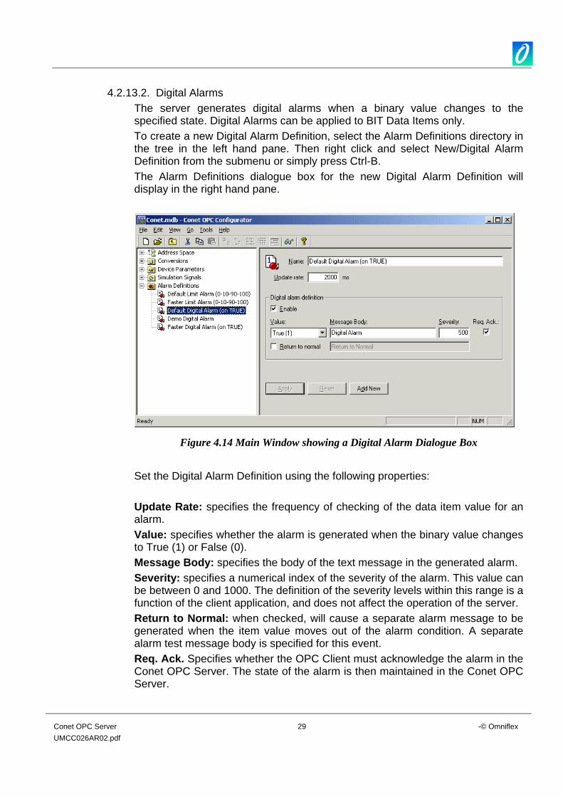
4.2.13.2. Digital Alarms The server generates digital alarms when a binary value changes to the specified state. Digital Alarms can be applied to BIT Data Items only. To create a new Digital Alarm Definition, select the Alarm Definitions directory in the tree in the left hand pane. Then right click and select New/Digital Alarm Definition from the submenu or simply press Ctrl-B. The Alarm Definitions dialogue box for the new Digital Alarm Definition will display in the right hand pane.
Figure 4.14 Main Window showing a Digital Alarm Dialogue Box
Set the Digital Alarm Definition using the following properties: Update Rate: specifies the frequency of checking of the data item value for an alarm. Value: specifies whether the alarm is generated when the binary value changes to True (1) or False (0). Message Body: specifies the body of the text message in the generated alarm. Severity: specifies a numerical index of the severity of the alarm. This value can be between 0 and 1000. The definition of the severity levels within this range is a function of the client application, and does not affect the operation of the server. Return to Normal: when checked, will cause a separate alarm message to be generated when the item value moves out of the alarm condition. A separate alarm test message body is specified for this event. Req. Ack. Specifies whether the OPC Client must acknowledge the alarm in the Conet OPC Server. The state of the alarm is then maintained in the Conet OPC Server.
Conet OPC Server 30 -© Omniflex UMCC026AR02.pdf
4.2.14 Using a Maxilarm The Maxilarm node must be set up correctly to transmit required timestamp events to the server. The Maxilarm node must send the event to a destination address which is the address of the first Conet PCI Card on the machine. NB. When timestamping for a certain input, from the maxilarm node is required, the following needs to be done: • Create a DIT BIT dataitem . • Set the appropriate DIT Number and DIT BIT Number. • Check the 'Timestamp Event from target' checkbox. (1) Time Sync Master - This allows the user to specify whether the current Maxilarm is
a time sync master or not. There can only be one time sync master on a given Conet Network. If no Maxilarm is chosen as a time sync master, the PC time is then used to synchronise all the Maxilarms on the network. If a Maxilarm is chosen as a time sync master, the PC time as well as all the other Maxilarms on the network will be updated with this time.
(2) Log Events - This logs events to a text file. The text filename will be 'OPCLog.txt'
and it is located in the windows system directory. Events for the inputs are logged in the following format:
Event Counter Date/Time Input Number Input Status Diagnostics: • Logging of Errors is implemented. If an event was possibly missed, it is logged
in the file. • Communications Errors are also logged.
4.2.15 Using the SER 260
The SER is a 4064 point distributed digital data acquisition system with 1ms resolution on all inputs. One SER system may consist of up to 32 subracks, each with a maximum of 512 inputs but not exceeding a total of 4064 points. The SER is designed to interface to supervisory computers for the purposes of data acquisition, event analysis and reporting. The technique used in this communication is one of computer command and SER reply. Select the 'Node type' to be 'SER 160/260'. By using the following fields communication with the SER can be configured: (3) SER Head Pointer - This allows you to select which History queue you wish data
to be read from on the SER260; 1, 2, 3 or 4. This means that up to 4 PC's with the Conet/c OPC Server (or any other package that reads from the SER260) can get data from the same SER260 simultaneously, by using different queue heads. Each
Conet OPC Server 31 -© Omniflex UMCC026AR02.pdf
PC must then use a different queue head. The Master of the history queue is used to determine whether or not the History Queue must cease being updated then the pointer lags by the maximum number of records in the History Queue, which is 825 records.
(4) Time Sync Master - This allows the user to specify whether the current SER is a
time sync master or not. There can only be one time sync master on a given Conet Network. If no SER is chosen as a time sync master, the PC time is then used to synchronise all the SERs on the network. If an SER is chosen as a time sync master, the PC time as well as all the other SERs on the network will be updated with this time.
(5) Log Events - This logs events to a text file. The text filename will be 'OPCLog.txt'
and it is located in the windows system directory. Events for the inputs are logged in the following format:
Event Counter
Date/Time Node Address
Head Pointer
Input Number
Input Status
Diagnostics: • Special Events (such as Power Failed, Power Returned) are also logged. • Logging of Errors is implemented. If an event was possibly missed, it is logged
in the file. • Communications Errors are also logged.
4.2.16 Using M126x with Queue support
Certain M126x CPUs support queues where timestamped events can be read and displayed using the OPC server. To enable timestamping from the queue do the following: (1) Enable ‘Use timestamp from Queued events’ at the device level. (2) The default Queue Number is 0 and the default head number is 0. (3) Enabling Logging Events if you wish to log the incoming queue events to a text file.
The OPCLog.txt file can be found in the windows system32 folder. (4) Enable the time sync check box if you wish to have time sync events either sent to
the device or have the pc time change to the device’s time. If ‘Time Sync Master’ is not checked then the pc uses it’s time to set the device’s time. If ‘Time Sync Master’ is checked then the pc sets it’s time according to the device’s time. Disabling time sync master is the preferred option.
(5) To create a data item that retrieves it’s timestamp from the queue, the data item needs to be created as follows:
a. The ’DIT BIT’ data type must be selected b. ‘Use timestamp from target’ must be selected.
Conet OPC Server 32 -© Omniflex UMCC026AR02.pdf
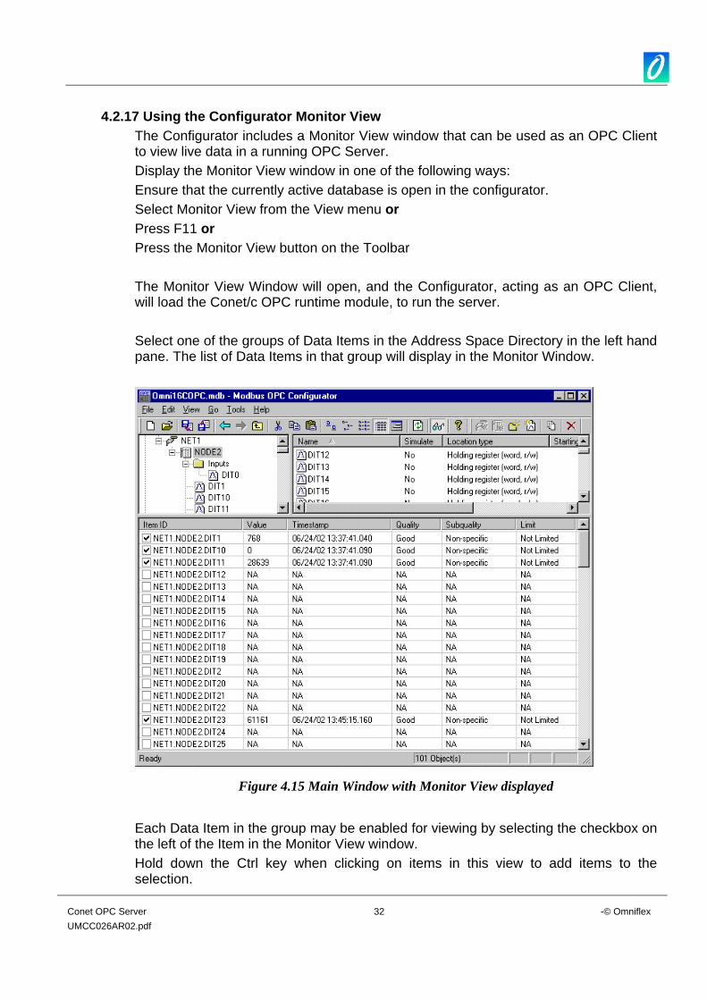
4.2.17 Using the Configurator Monitor View The Configurator includes a Monitor View window that can be used as an OPC Client to view live data in a running OPC Server. Display the Monitor View window in one of the following ways: Ensure that the currently active database is open in the configurator. Select Monitor View from the View menu or Press F11 or Press the Monitor View button on the Toolbar The Monitor View Window will open, and the Configurator, acting as an OPC Client, will load the Conet/c OPC runtime module, to run the server. Select one of the groups of Data Items in the Address Space Directory in the left hand pane. The list of Data Items in that group will display in the Monitor Window.
Figure 4.15 Main Window with Monitor View displayed
Each Data Item in the group may be enabled for viewing by selecting the checkbox on the left of the Item in the Monitor View window. Hold down the Ctrl key when clicking on items in this view to add items to the selection.
Conet OPC Server 33 -© Omniflex UMCC026AR02.pdf
Hold down the Shift key to select ranges of items in this view. To enable/disable a selection of items, right click on the items and select Enable Monitoring or Disable Monitoring. NOTE: The Conet OPC Server runtime will NOT unload of the Monitor View is turned off. The Configurator must be closed and restarted to reload the runtime module of the server with a modified database after the Monitor View has been displayed.
4.3 Running the Conet OPC Server The OPC Server Runtime module is a Microsoft Active X object and has no user interface. Once installed and registered on the computer, the Conet OPC Server runtime module will automatically start when any OPC client tries to access the server, and will shut down when the last OPC Client closes all links with the Conet OPC Server. 4.3.1 Determining if the server is running.
Because the runtime module has no user interface, the only way to determine that the Conet OPC Server is running, other than checking through a loaded OPC Client is via the operating system’s task manager. In Windows98 press Ctrl-Alt and then Delete. When the task list box pops up, check for the presence of the Conet OPC Server in the list of running processes. In Windows 2000 press the Ctrl-Alt and then Delete keys. Select the Task Manager from the dialogue box that appears. When the task list box pops up, check for the presence of the Conet OPC Server in the list of running processes.
4.3.2 Selecting the correct Database to use in the Runtime module. The Conet OPC Server Runtime module will load the database specified in the Configurator as “Active” when it starts. This “Active” database is loaded into memory and is not read again until next time the runtime module starts. This provides you with the ability edit the existing database without affecting the currently running server. To invoke the changes made, you must stop the server by closing all running OPC clients, and then restart the server by restarting one of the OPC clients. NOTE: The Monitor window in the OPC Configurator is itself an OPC Client. If the Monitor window has been opened in the Configurator, then the Configurator will be seen by the OPC Server Runtime module as an active client and will not shutdown, even if all other clients are closed. If the Configurator Monitor window has been opened, then the Configurator must be shutdown and restarted to reload any changes made to the database into the Conet OPC Server Runtime module.
Conet OPC Server 34 -© Omniflex UMCC026AR02.pdf
5. RUNNING THE SAMPLE OPC CLIENT
5.1 Introduction The Sample OPC Test Client supplied with the Conet OPC Server can be used to test/debug your configuration of the OPC Server. This application is a simple OPC Client that creates a single OPC Group in the OPC Server containing the list of OPC Items that you add to the list in the Sample Client.
5.2 Installing the Sample OPC Client The Sample OPC Client is installed together with the Conet OPC Server. No further action is required.
5.3 Using the Sample OPC Client 5.3.1 Starting the Sample OPC
To Start the Sample OPC Client, Choose “Sample OPC Client” from the Conet OPC Server Program Group in the Start menu (normally found under the Omniflex Program Group).
5.3.2 To Connect the Sample Client to the Conet OPC Server
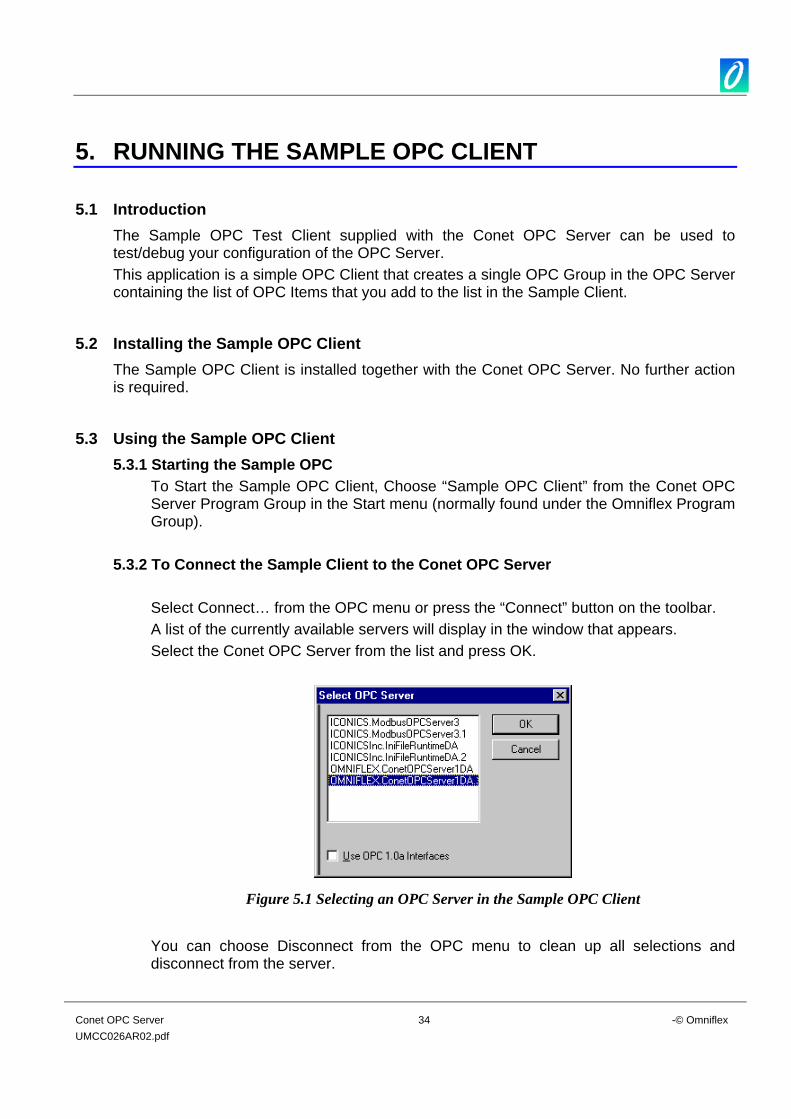
Select Connect… from the OPC menu or press the “Connect” button on the toolbar. A list of the currently available servers will display in the window that appears. Select the Conet OPC Server from the list and press OK.
Figure 5.1 Selecting an OPC Server in the Sample OPC Client
You can choose Disconnect from the OPC menu to clean up all selections and disconnect from the server.
Conet OPC Server 35 -© Omniflex UMCC026AR02.pdf
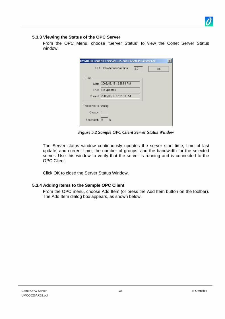
5.3.3 Viewing the Status of the OPC Server From the OPC Menu, choose “Server Status” to view the Conet Server Status window.
Figure 5.2 Sample OPC Client Server Status Window
The Server status window continuously updates the server start time, time of last update, and current time, the number of groups, and the bandwidth for the selected server. Use this window to verify that the server is running and is connected to the OPC Client. Click OK to close the Server Status Window.
5.3.4 Adding Items to the Sample OPC Client From the OPC menu, choose Add Item (or press the Add Item button on the toolbar). The Add Item dialog box appears, as shown below.
Conet OPC Server 36 -© Omniflex UMCC026AR02.pdf
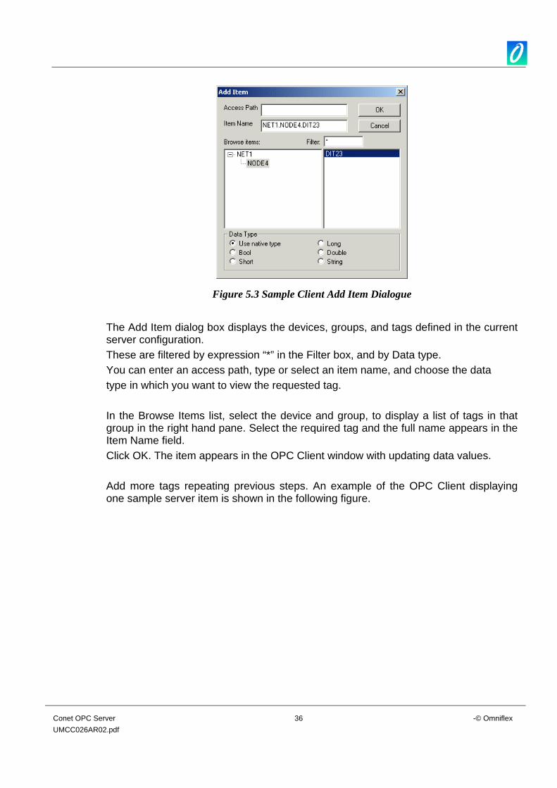
Figure 5.3 Sample Client Add Item Dialogue
The Add Item dialog box displays the devices, groups, and tags defined in the current server configuration. These are filtered by expression “*” in the Filter box, and by Data type. You can enter an access path, type or select an item name, and choose the data type in which you want to view the requested tag. In the Browse Items list, select the device and group, to display a list of tags in that group in the right hand pane. Select the required tag and the full name appears in the Item Name field. Click OK. The item appears in the OPC Client window with updating data values. Add more tags repeating previous steps. An example of the OPC Client displaying one sample server item is shown in the following figure.
Conet OPC Server 37 -© Omniflex UMCC026AR02.pdf
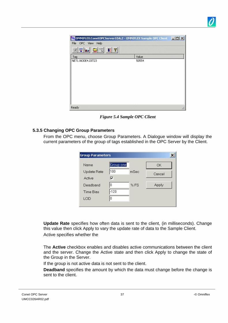
Figure 5.4 Sample OPC Client
5.3.5 Changing OPC Group Parameters
From the OPC menu, choose Group Parameters. A Dialogue window will display the current parameters of the group of tags established in the OPC Server by the Client.
Update Rate specifies how often data is sent to the client, (in milliseconds). Change this value then click Apply to vary the update rate of data to the Sample Client. Active specifies whether the The Active checkbox enables and disables active communications between the client and the server. Change the Active state and then click Apply to change the state of the Group in the Server. If the group is not active data is not sent to the client. Deadband specifies the amount by which the data must change before the change is sent to the client.
Conet OPC Server 38 -© Omniflex UMCC026AR02.pdf
5.3.6 Running Multiple Sample Clients Start another instance of the OPC Client and make the same server connection as those defined in the first Client instance. You can add items, change the group update rate and active states, and view the server status in each instance of the OPC Client independently of the other instance. The number of groups is "1" in each client because each one only has one group, even though there will be two groups created in the OPC Server. Even the Group names are the same in each of the clients. The only way that one client affects the other is through data and data changes.
5.3.7 How Sample OPC Clients get data from the OPC Server To add a data item to the Sample Client, the “Add Item” window displays either a hierarchy of OPC Item name from the Conet OPC Server. The names are queried from the Server using the filter string and requested data type. When the user either types or selects a name, an item by that name is added to the Group in the Server on behalf of the Sample Client. This item is also read immediately to get an initial value. The server scans items in a group. When any Item values change, the “Advise” interface in the client is notified. A data structure containing the data for each item whose value or quality has changed (and only those items) is passed to the client’s advise interface. The client unpacks and uses the data. When a group is inactive, it does not send data notifications to the client and, typically there is no reason to scan the items when the group is inactive. The Update Rate in the Group Parameters dialog box specifies the maximum rate at which data notifications should be sent. This is also the rate at which items are scanned on behalf of this client. The Server status dialog periodically queries the Server and displays the results. The user can disconnect from the selected server by choosing Disconnect from the OPC menu, The Disconnect command unregisters the client interface, releases the Group in the server, and then releases the Server. The system can then delete the group, and if no other clients are connected to the server, can shut the server down.
5.3.8 Writing Data from the Client to the Server/Device in the field. To write a value to an item, select the item in the OPC Client windows and choose “Write Value to Item” from the OPC menu. The client writes the value typed in the Write Item Value dialog box to the correct item in the Group. The method of writing data is determined by the “Asynchronous” checkbox. When data is written “synchronously” (checkbox unchecked), the client waits until the operation has completed before resuming its normal operation. When data is written “asynchronously”, the “Write” command to the server returns control immediately to the client. The “Write” operation is carried out by the OPC Server in the background. When the “Write” has finished, the client’s advise interface is notified with the results.