Embed Size (px)
Citation preview
1
Cone Beam Reconstruction
Jiang Hsieh, Ph.D.
Applied Science Laboratory, GE Healthcare Technologies
2
Image GenerationReconstruction of images from projections.Reconstruction of images from projections.
“textbook” reconstruction“textbook” reconstructionadvanced acquisition (helical, multiadvanced acquisition (helical, multi--slice)slice)advanced application (cardiac, perfusion)advanced application (cardiac, perfusion)
Formulation of 2D images to 3D volume.Formulation of 2D images to 3D volume.
Presentationreconstruction
3
“Textbook” Reconstruction
The mathematical foundation of CT can be traced The mathematical foundation of CT can be traced back to 1917 to Radon.back to 1917 to Radon.The algorithms can be classified into two classes: The algorithms can be classified into two classes: analytical and iterative.analytical and iterative.Some of the commonly used reconstruction Some of the commonly used reconstruction formula was developed in the late 70s and early formula was developed in the late 70s and early 80s.80s.With the introduction of multiWith the introduction of multi--slice helical CT, slice helical CT, new cone beam reconstruction algorithms are new cone beam reconstruction algorithms are developed.developed.
4
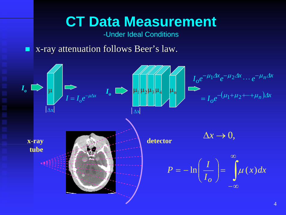
CT Data Measurement-Under Ideal Conditions
xx--ray attenuation follows Beer’s law.ray attenuation follows Beer’s law.
Io
I I eox= −µ∆
∆x
µ Io
xxxo neeeI ∆µ∆µ∆µ −−− ⋅⋅⋅21
∆x
µ1µ2µ3 µ4 µn ( ) xo neI ∆µµµ ⋅+⋅⋅++−= 21
x-ray tube
,0→∆xdetector
∫∞
∞−
=⎟⎟⎠
⎞⎜⎜⎝
⎛−= dxx
IIPo
)(ln µ

5
Ideal Projections
The measured data are not line integrals of The measured data are not line integrals of attenuation coefficients of the object.attenuation coefficients of the object.
beam hardeningbeam hardeningscattered radiationscattered radiationdetector and data acquisition nondetector and data acquisition non--linearitylinearitypatient motionpatient motionothersothers
The data need to be calibrated prior to the The data need to be calibrated prior to the tomographic reconstruction to obtain artifacttomographic reconstruction to obtain artifact--free free images.images.
6
Sampling Geometries
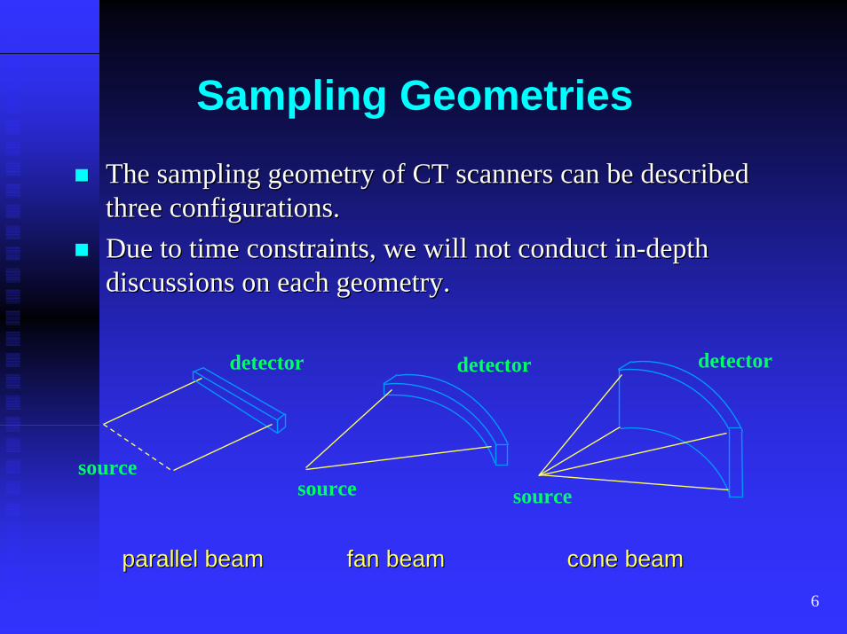
The sampling geometry of CT scanners can be described The sampling geometry of CT scanners can be described three configurations.three configurations.Due to time constraints, we will not conduct inDue to time constraints, we will not conduct in--depth depth discussions on each geometry.discussions on each geometry.
detector
source
detector
source
detector
source
parallel beamparallel beam fan beamfan beam cone beamcone beam
7
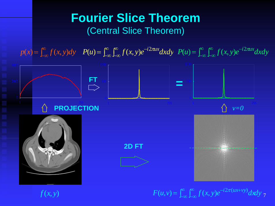
Fourier Slice Theorem(Central Slice Theorem)
2D FT
),( yxf dydxeyxfvuF vyuxi∫ ∫∞∞−
∞∞−
+−= )(2),(),( π
∫∞∞−= dyyxfxp ),()( ∫ ∫
∞∞−
∞∞−
−= dxdyeyxfuP uxi π2),()( ∫ ∫∞∞−
∞∞−
−= dxdyeyxfuP uxi π2),()(
0
2000
4000
1 2550
500
1000
1 255
FT =
v=0PROJECTION0
500
1000
1 255
8
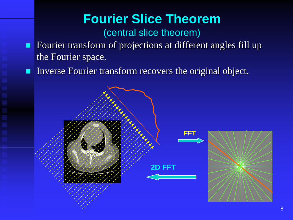
Fourier Slice Theorem(central slice theorem)
Fourier transform of projections at different angles fill up Fourier transform of projections at different angles fill up the Fourier space.the Fourier space.Inverse Fourier transform recovers the original object.Inverse Fourier transform recovers the original object.
2D FFT
FFT
9
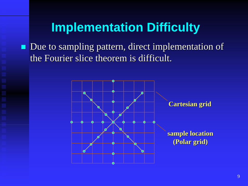
Implementation DifficultyDue to sampling pattern, direct implementation of Due to sampling pattern, direct implementation of the Fourier slice theorem is difficult.the Fourier slice theorem is difficult.
Cartesian gridCartesian grid
sample locationsample location(Polar grid)(Polar grid)
10
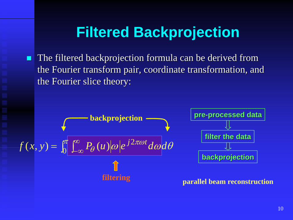
Filtered BackprojectionThe filtered backprojection formula can be derived from The filtered backprojection formula can be derived from the Fourier transform pair, coordinate transformation, and the Fourier transform pair, coordinate transformation, and the Fourier slice theory:the Fourier slice theory:
prepre--processed dataprocessed databackprojection
filter the datafilter the data
backprojectionbackprojection∫ ∫= π ∞
∞−πω
θ ωω 2)( ddeuP tj θ0),( yxf
filtering parallel beam reconstruction
11
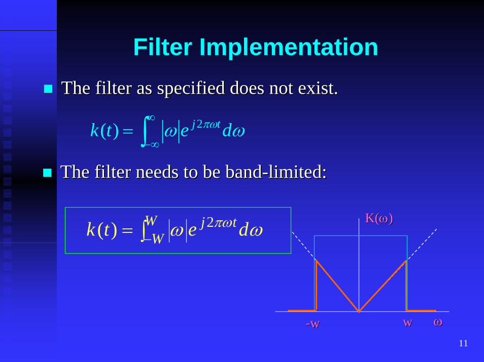
Filter ImplementationThe filter as specified does not exist.The filter as specified does not exist.
∫∞
∞−= ωω πω detk tj2)(
The filter needs to be bandThe filter needs to be band--limited:limited:
∫−= WW
tj detk ωω πω2)( K(K(ωω))
ωω--ww ww
12
Filtered Backprojection-an intuitive explanation
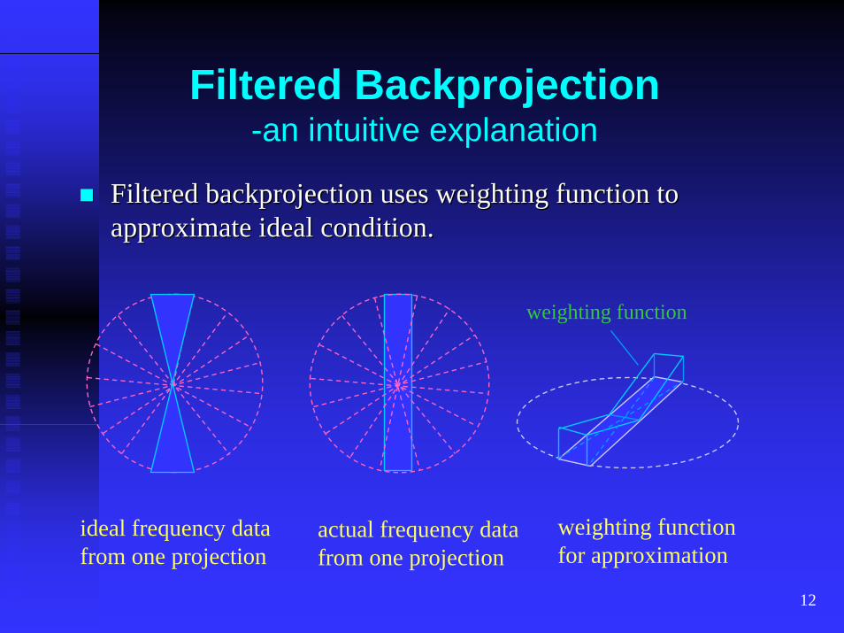
Filtered backprojection uses weighting function to Filtered backprojection uses weighting function to approximate ideal condition.approximate ideal condition.
weighting function
weighting functionfor approximation
ideal frequency datafrom one projection
actual frequency datafrom one projection
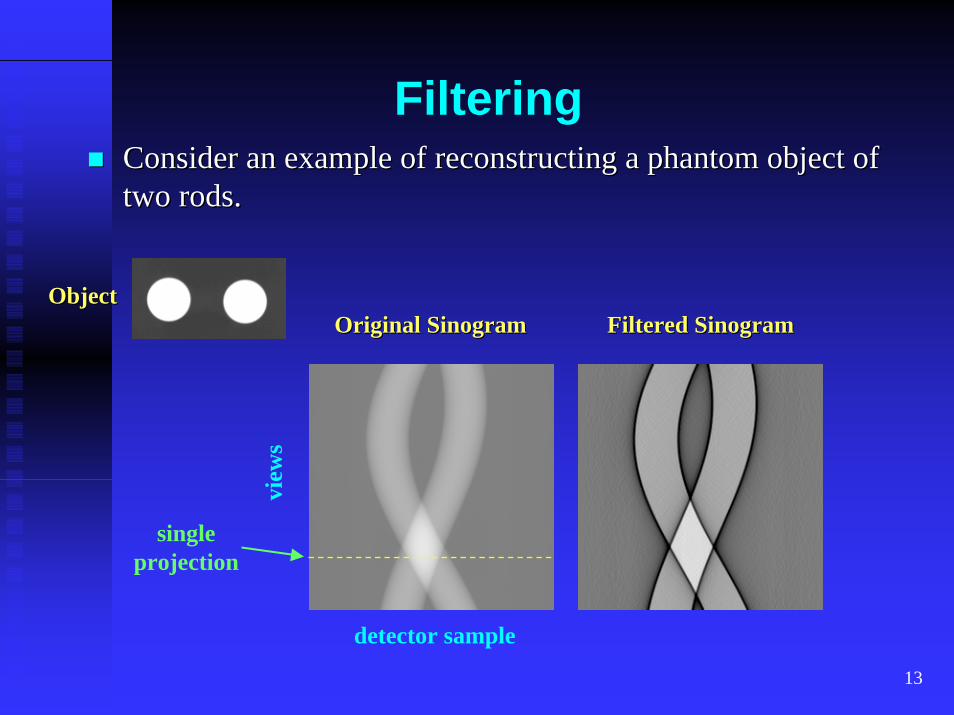
13
FilteringConsider an example of reconstructing a phantom object of Consider an example of reconstructing a phantom object of two rods.two rods.
ObjectObjectOriginal SinogramOriginal Sinogram Filtered SinogramFiltered Sinogram
view
s
singleprojection
detector sample
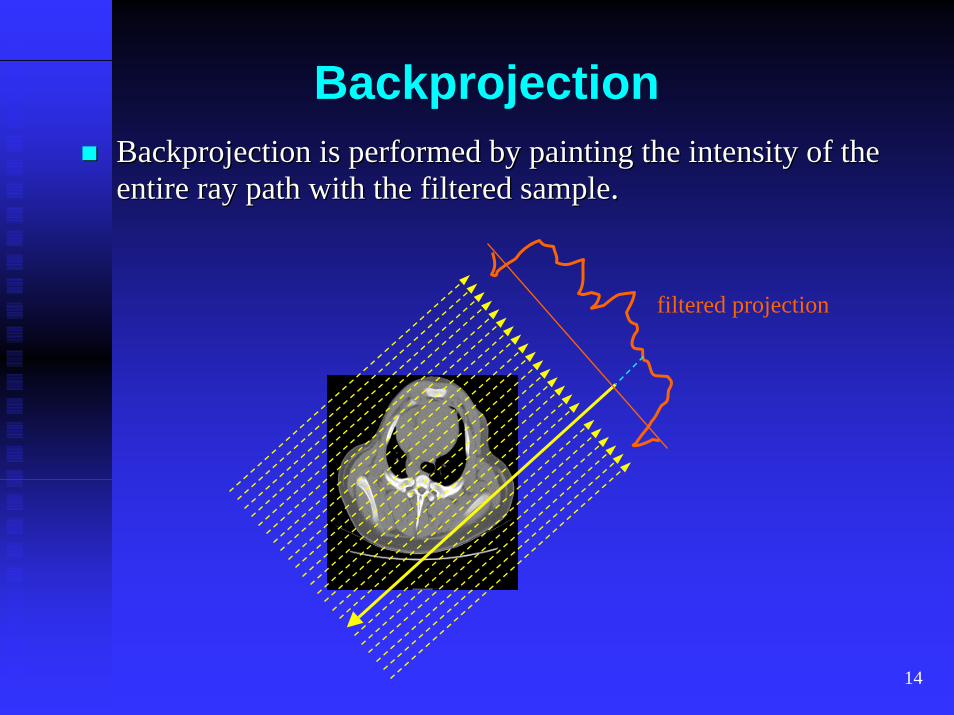
14
BackprojectionBackprojection is performed by painting the intensity of the Backprojection is performed by painting the intensity of the entire ray path with the filtered sampleentire ray path with the filtered sample..
filtered projection
15
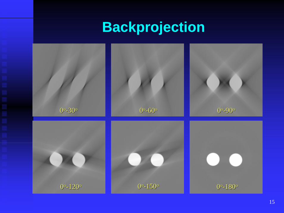
Backprojection
00oo--3030oo 00oo--6060oo 00oo--9090oo
00oo--150150oo00oo--120120oo 00oo--180180oo
16
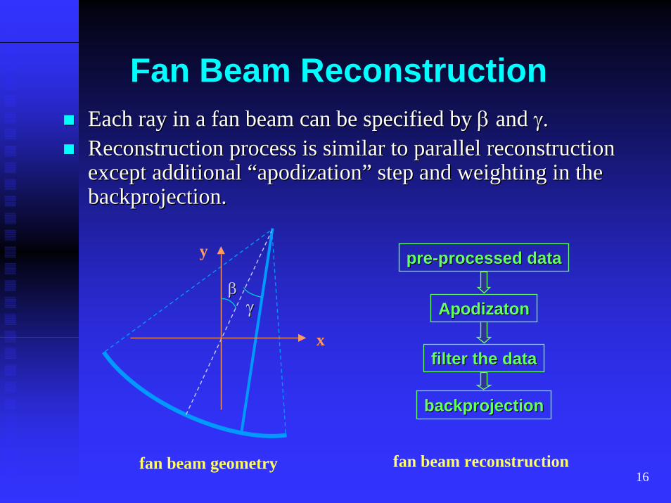
Fan Beam Reconstruction
prepre--processed dataprocessed data
filter the datafilter the data
backprojectionbackprojection
Each ray in a fan beam can be specified by Each ray in a fan beam can be specified by ββ and and γγ..Reconstruction process is similar to parallel reconstruction Reconstruction process is similar to parallel reconstruction except additional “apodization” step and weighting in the except additional “apodization” step and weighting in the backprojection.backprojection.
fan beam geometry
x
y
ββγγ ApodizatonApodizaton
fan beam reconstruction
17
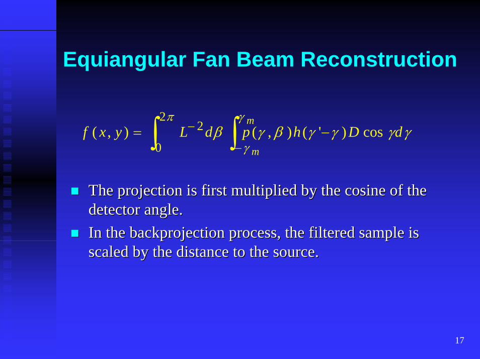
Equiangular Fan Beam Reconstruction
∫ ∫−
− −=π γ
γγγγγβγβ
2
0
2 cos)'(),(),(m
m
dDhpdLyxf
The projection is first multiplied by the cosine of the The projection is first multiplied by the cosine of the detector angle.detector angle.In the backprojection process, the filtered sample is In the backprojection process, the filtered sample is scaled by the distance to the source.scaled by the distance to the source.
18
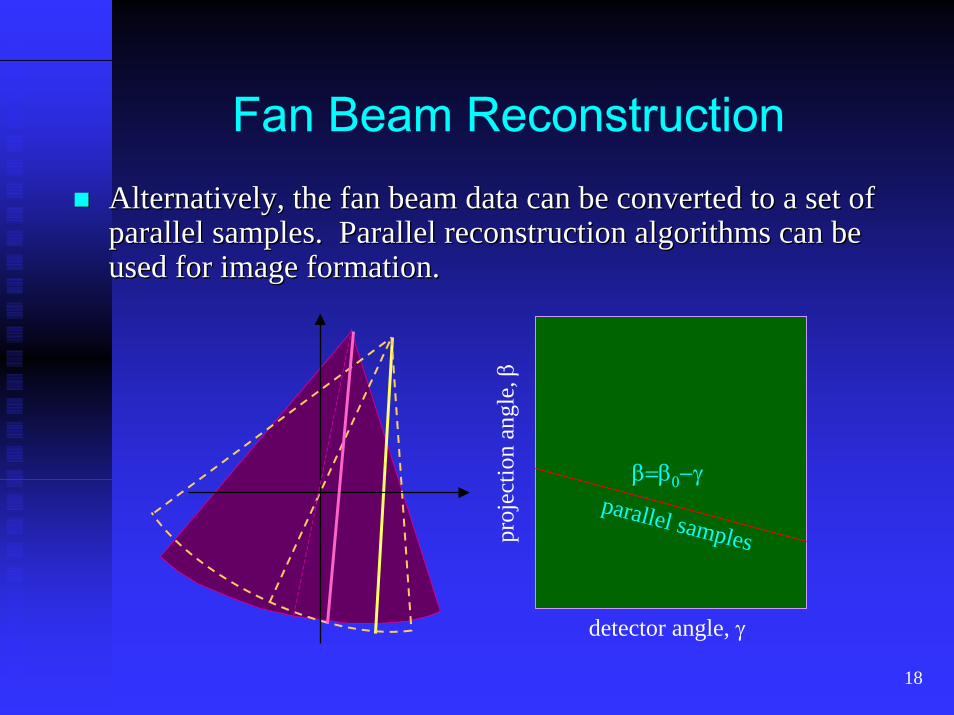
Fan Beam ReconstructionAlternatively, the fan beam data can be converted to a set of Alternatively, the fan beam data can be converted to a set of parallel samples. Parallel reconstruction algorithms can be parallel samples. Parallel reconstruction algorithms can be used for image formation.used for image formation.
detector angle, γ
proj
ectio
n an
gle,
ββ=β0−γ
parallel samples
19
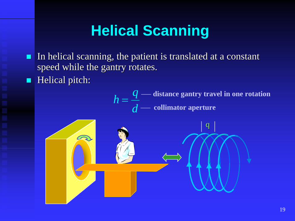
Helical ScanningIn helical scanning, the patient is translated at a constant In helical scanning, the patient is translated at a constant speed while the gantry rotates.speed while the gantry rotates.Helical pitch: Helical pitch:
dqh = distance gantry travel in one rotation
collimator aperture
20
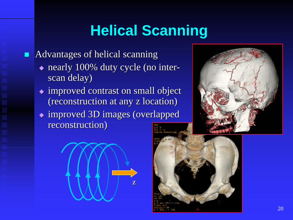
Helical ScanningAdvantages of helical scanningAdvantages of helical scanning
nearly 100% duty cycle (no internearly 100% duty cycle (no inter--scan delay)scan delay)improved contrast on small object improved contrast on small object (reconstruction at any z location)(reconstruction at any z location)improved 3D images (overlapped improved 3D images (overlapped reconstruction)reconstruction)
zz
21
Helical Scanning
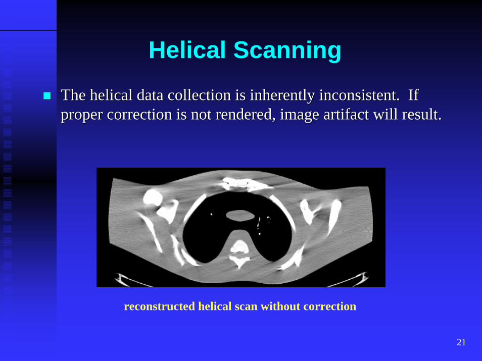
The helical data collection is inherently inconsistent. If The helical data collection is inherently inconsistent. If proper correction is not rendered, image artifact will result.proper correction is not rendered, image artifact will result.
reconstructed helical scan without correction
22
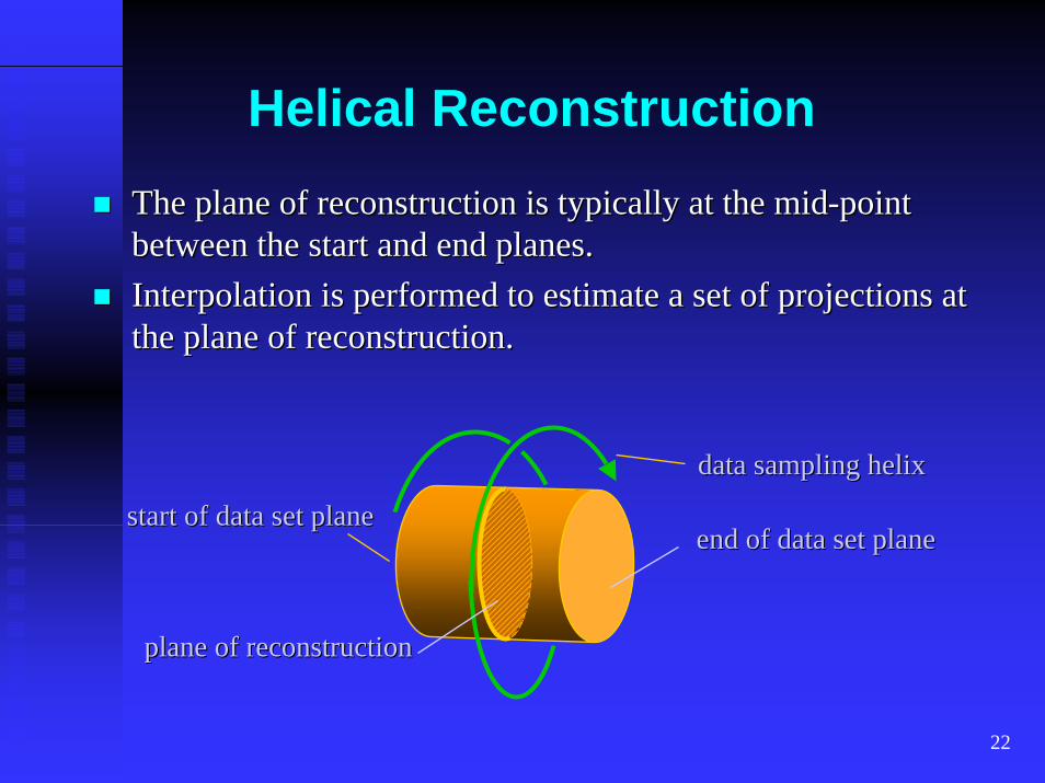
Helical ReconstructionThe plane of reconstruction is typically at the midThe plane of reconstruction is typically at the mid--point point between the start and end planes.between the start and end planes.Interpolation is performed to estimate a set of projections at Interpolation is performed to estimate a set of projections at the plane of reconstruction.the plane of reconstruction.
data sampling helixdata sampling helix
plane of reconstructionplane of reconstruction
start of data set planestart of data set planeend of data set planeend of data set plane
23
Helical Reconstruction-360o interpolation
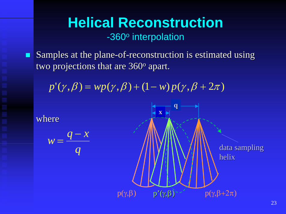
Samples at the planeSamples at the plane--ofof--reconstruction is estimated using reconstruction is estimated using two projections that are 360two projections that are 360oo apart.apart.
)2,()1(),(),(' πβγβγβγ +−+= pwwpp
data sampling data sampling helixhelix
p(γ,β) p(γ,β+2π)p’(p’(γ,βγ,β))
xxqq
wherewhere
qxqw −
=
24
Helical Reconstruction-180o interpolation
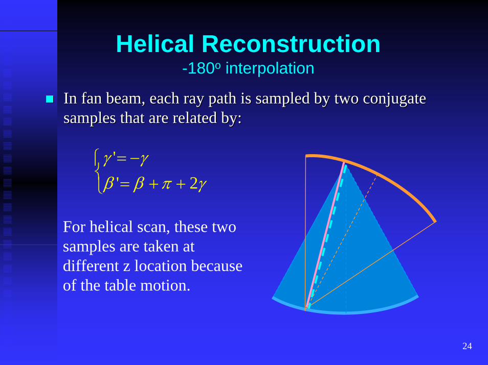
In fan beam, each ray path is sampled by two conjugate In fan beam, each ray path is sampled by two conjugate samples that are related by:samples that are related by:
⎩⎨⎧
++=−=
γπββγγ
2''
For helical scan, these two samples are taken at different z location because of the table motion.
25
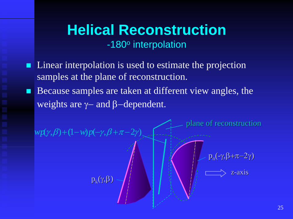
Helical Reconstruction-180o interpolation
Linear interpolation is used to estimate the projection samples at the plane of reconstruction.Because samples are taken at different view angles, the weights are γ− and β−dependent.
plane of reconstructionplane of reconstruction
ppkk((γ,βγ,β))
ppnn((--γ,β+πγ,β+π−−2γ2γ))
)2,()1(),( γπβγβγ −+−−+ pwwp
zz--axisaxis
26
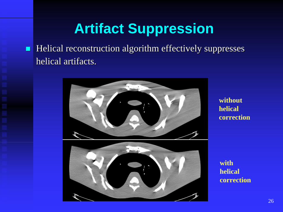
Artifact SuppressionHelical reconstruction algorithm effectively suppresses Helical reconstruction algorithm effectively suppresses helical artifacts.helical artifacts.
withouthelicalcorrection
with helicalcorrection
27
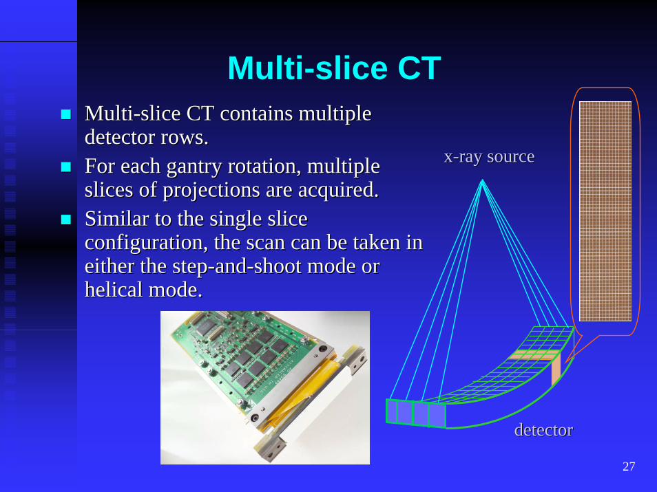
Multi-slice CTMultiMulti--slice CT contains multiple slice CT contains multiple detector rows.detector rows.For each gantry rotation, multiple For each gantry rotation, multiple slices of projections are acquired.slices of projections are acquired.Similar to the single slice Similar to the single slice configuration, the scan can be taken in configuration, the scan can be taken in either the stepeither the step--andand--shoot mode or shoot mode or helical mode. helical mode.
xx--ray sourceray source
detectordetector
28
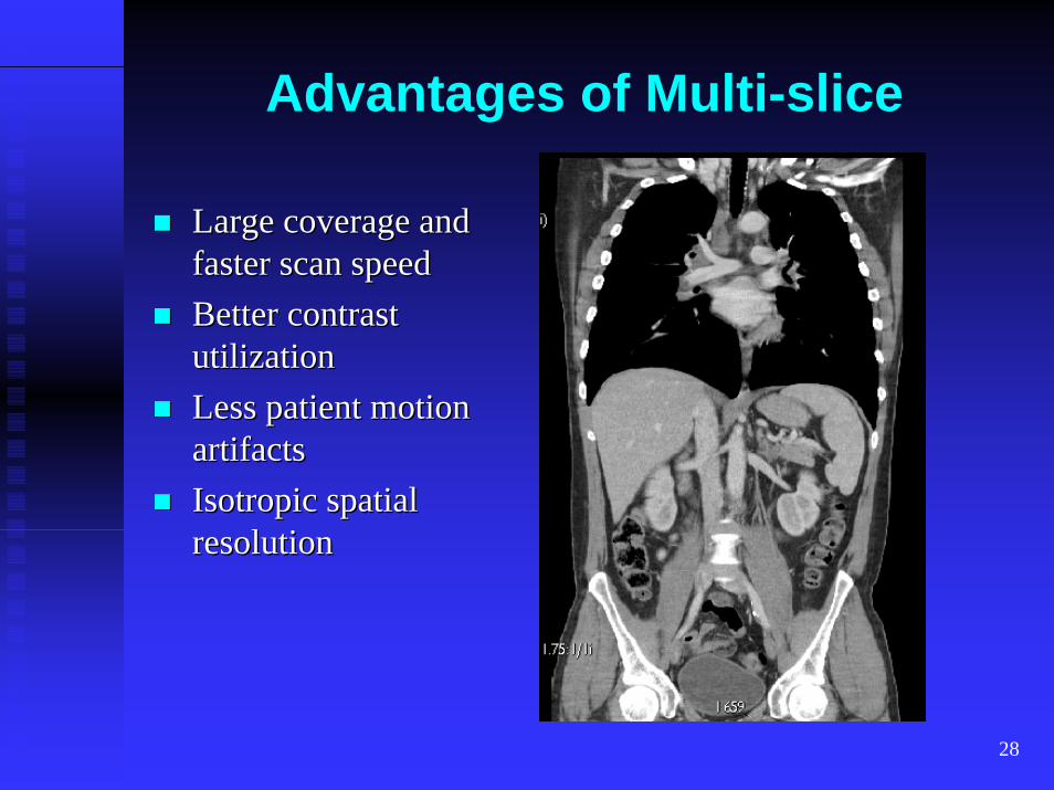
Advantages of Multi-slice
Large coverage and Large coverage and faster scan speedfaster scan speedBetter contrast Better contrast utilizationutilizationLess patient motion Less patient motion artifactsartifactsIsotropic spatial Isotropic spatial resolutionresolution
29
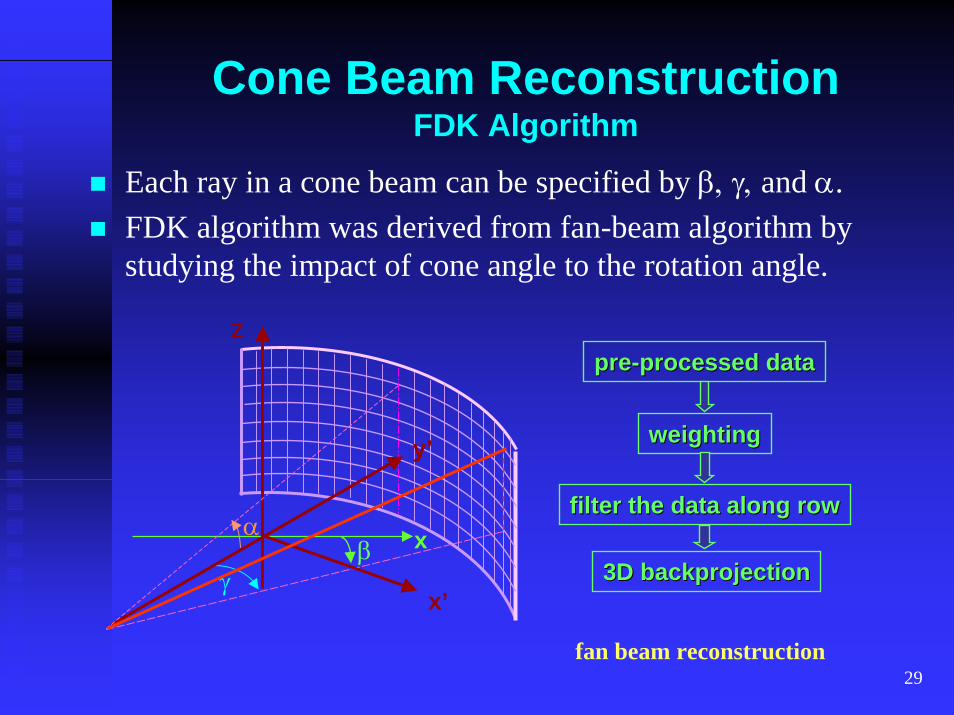
Cone Beam ReconstructionFDK Algorithm
Each ray in a cone beam can be specified by β, γ, and α.FDK algorithm was derived from fan-beam algorithm by studying the impact of cone angle to the rotation angle.
zprepre--processed dataprocessed data
filter the data along rowfilter the data along row
3D backprojection3D backprojectionγβ
α
x’
y’
x
weightingweighting
fan beam reconstruction
30
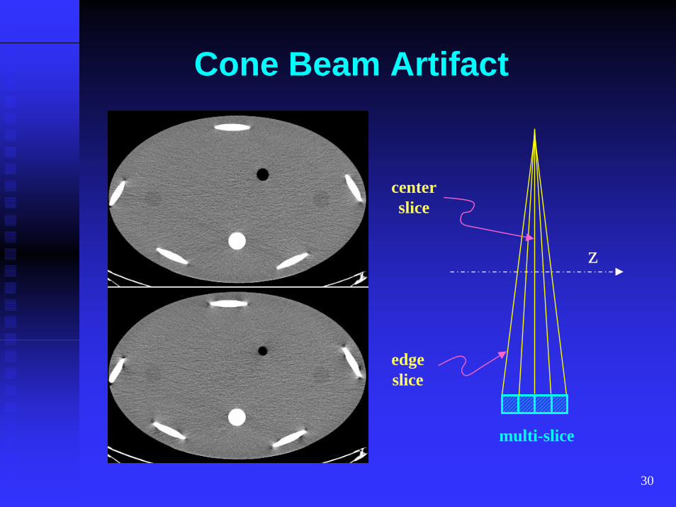
Cone Beam Artifact
centerslice
z
edgeslice
multi-slice
31
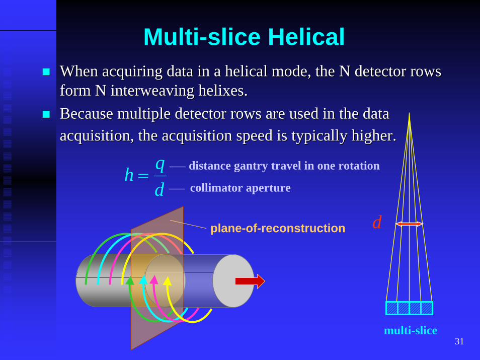
Multi-slice HelicalWhen acquiring data in a helical mode, the N detector rows When acquiring data in a helical mode, the N detector rows form N interweaving helixes.form N interweaving helixes.Because multiple detector rows are used in the data Because multiple detector rows are used in the data acquisition, the acquisition speed is typically higher.acquisition, the acquisition speed is typically higher.
dqh = distance gantry travel in one rotation
collimator aperture
multi-slice
dplane-of-reconstruction
32
Cone Beam Helical Reconstruction
Exact algorithms produce mathematically exact solutions when input projections are perfect.
KatsevichGrangeatRebin PHIFBP PHI
Approximate algorithms, although non-exact, generate clinically accurate images.
FDK-typeN-PICB-virtual circleTilted PlaneZB
33
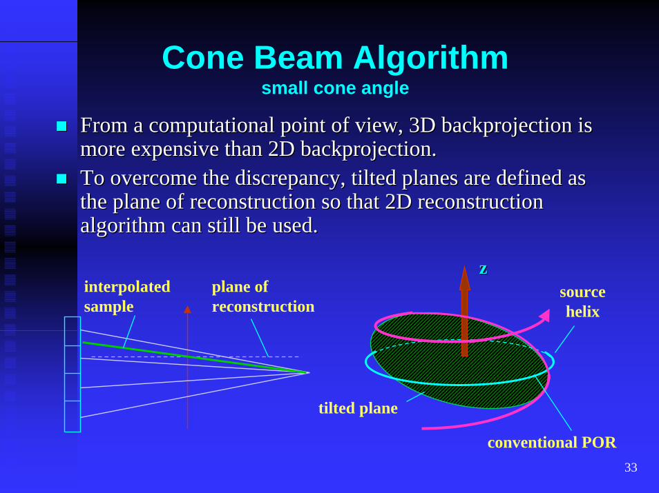
Cone Beam Algorithmsmall cone angle
From a computational point of view, 3D backprojection is From a computational point of view, 3D backprojection is more expensive than 2D backprojection.more expensive than 2D backprojection.To overcome the discrepancy, tilted planes are defined as To overcome the discrepancy, tilted planes are defined as the plane of reconstruction so that 2D reconstruction the plane of reconstruction so that 2D reconstruction algorithm can still be used.algorithm can still be used.
source helix
zz
tilted plane
conventional POR
interpolatedsample
plane of reconstruction
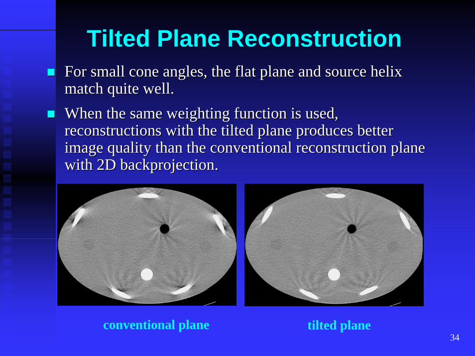
34
Tilted Plane ReconstructionFor small cone angles, the flat plane and source helix For small cone angles, the flat plane and source helix match quite well.match quite well.When the same weighting function is used, When the same weighting function is used, reconstructions with the tilted plane produces better reconstructions with the tilted plane produces better image quality than the conventional reconstruction plane image quality than the conventional reconstruction plane with 2D backprojection.with 2D backprojection.
tilted planeconventional plane
35
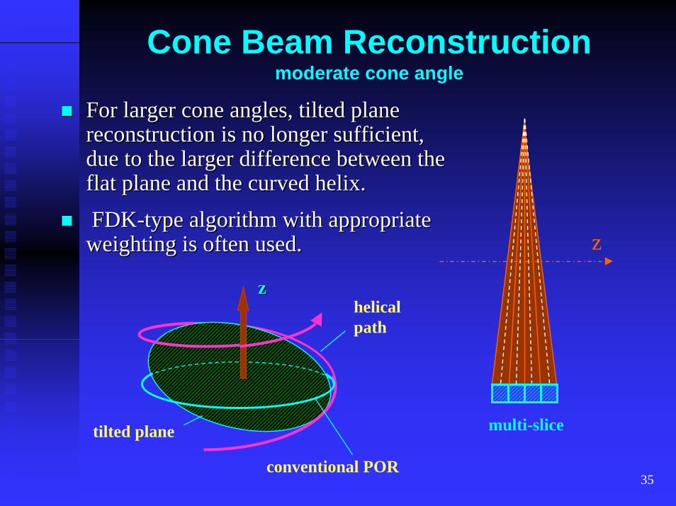
Cone Beam Reconstructionmoderate cone angle
For larger cone angles, tilted plane For larger cone angles, tilted plane reconstruction is no longer sufficient, reconstruction is no longer sufficient, due to the larger difference between the due to the larger difference between the flat plane and the curved helix.flat plane and the curved helix.
FDKFDK--type algorithm with appropriate type algorithm with appropriate weighting is often used. zweighting is often used.
helical path
zz
tilted plane
conventional POR
multi-slice
36
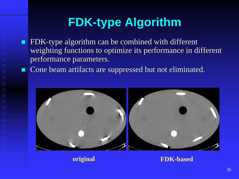
FDK-type AlgorithmFDKFDK--type algorithm can be combined with different type algorithm can be combined with different weighting functions to optimize its performance in different weighting functions to optimize its performance in different performance parameters.performance parameters.Cone beam artifacts are suppressed but not eliminated. Cone beam artifacts are suppressed but not eliminated.
original FDK-based
37
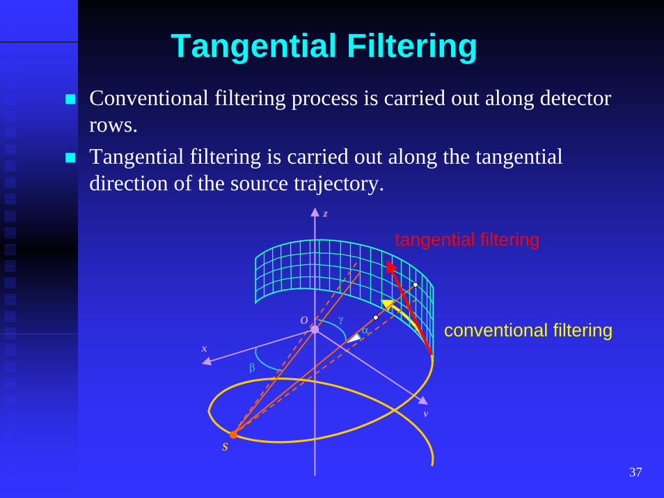
Tangential Filtering
x
y
z
S
β
α γ O
tangential filtering
conventional filtering
Conventional filtering process is carried out along detector rows.Tangential filtering is carried out along the tangential direction of the source trajectory.
38
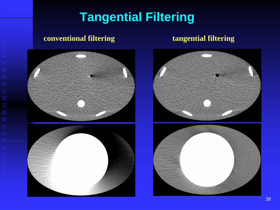
Tangential Filteringconventional filtering tangential filtering
39
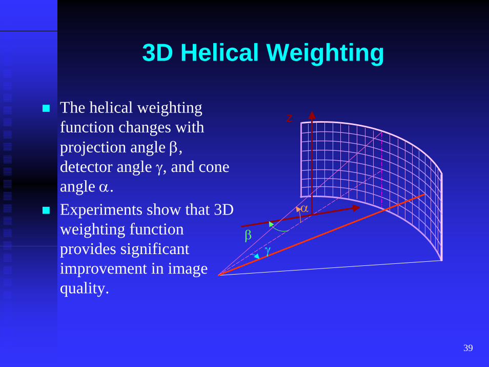
3D Helical Weighting
z
γβ
α
The helical weighting function changes with projection angle β, detector angle γ, and cone angle α.Experiments show that 3D weighting function provides significant improvement in image quality.
40
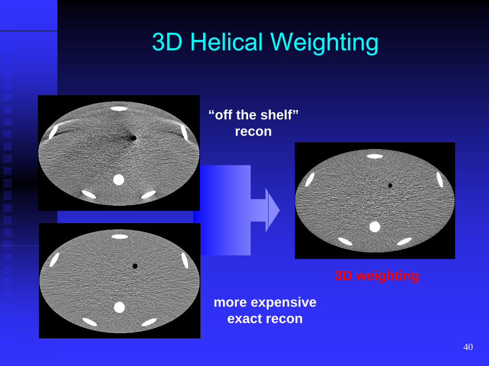
3D Helical Weighting
“off the shelf”recon
3D weighting
more expensiveexact recon
41
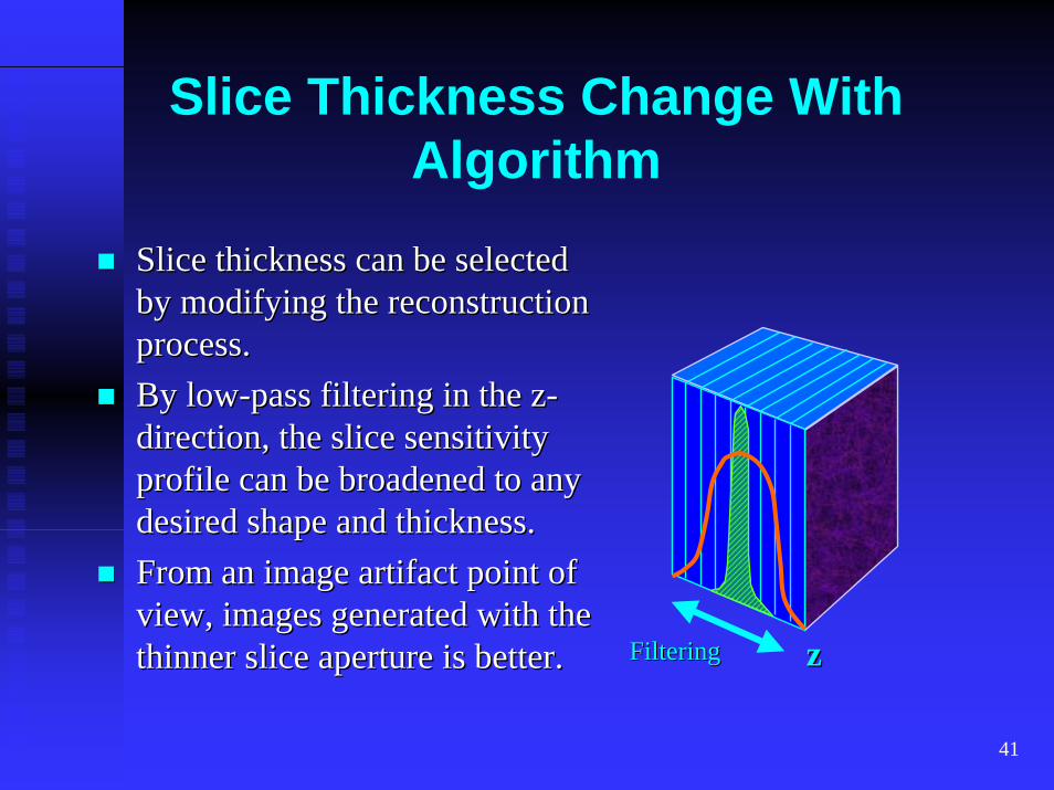
Slice Thickness Change With Algorithm
Slice thickness can be selected Slice thickness can be selected by modifying the reconstruction by modifying the reconstruction process.process.By lowBy low--pass filtering in the zpass filtering in the z--direction, the slice sensitivity direction, the slice sensitivity profile can be broadened to any profile can be broadened to any desired shape and thickness.desired shape and thickness.From an image artifact point of From an image artifact point of view, images generated with the view, images generated with the thinner slice aperture is better. FilteringFiltering zzthinner slice aperture is better.
42
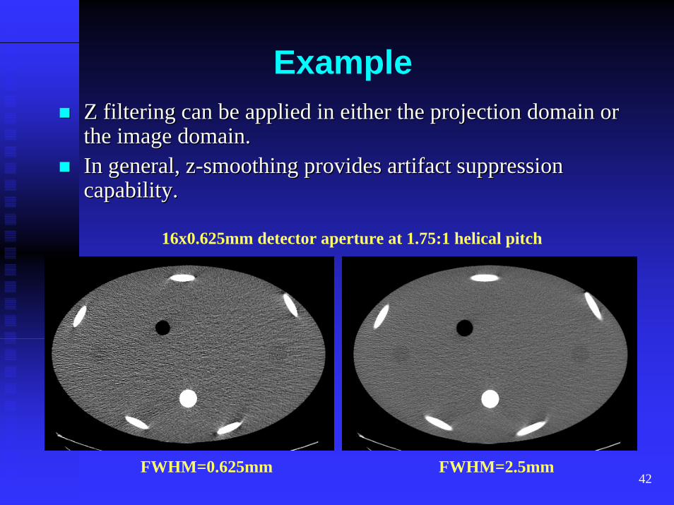
ExampleZ filtering can be applied in either the projection domain or Z filtering can be applied in either the projection domain or the image domain.the image domain.In general, zIn general, z--smoothing provides artifact suppression smoothing provides artifact suppression capability.capability.
16x0.625mm detector aperture at 1.75:1 helical pitch
FWHM=0.625mm FWHM=2.5mm
43
Cardiac Scans
The most challenging problem in cardiac scanning is The most challenging problem in cardiac scanning is motion.motion.Unlike respiratory motion, cardiac motion cannot be Unlike respiratory motion, cardiac motion cannot be voluntarily controlled.voluntarily controlled.For motion suppression, we could either reduce the For motion suppression, we could either reduce the acquisition time and/or acquire the data during the acquisition time and/or acquire the data during the minimum cardiac motion.minimum cardiac motion.In cardiac motion, there are relative quiescent period: In cardiac motion, there are relative quiescent period: diastolic phase of the heart motion.diastolic phase of the heart motion.
44
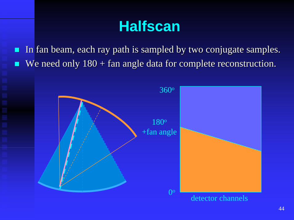
HalfscanIn fan beam, each ray path is sampled by two conjugate samples.In fan beam, each ray path is sampled by two conjugate samples.We need only 180 + fan angle data for complete reconstruction.We need only 180 + fan angle data for complete reconstruction.
360o
180o
+fan angle
0odetector channels
45
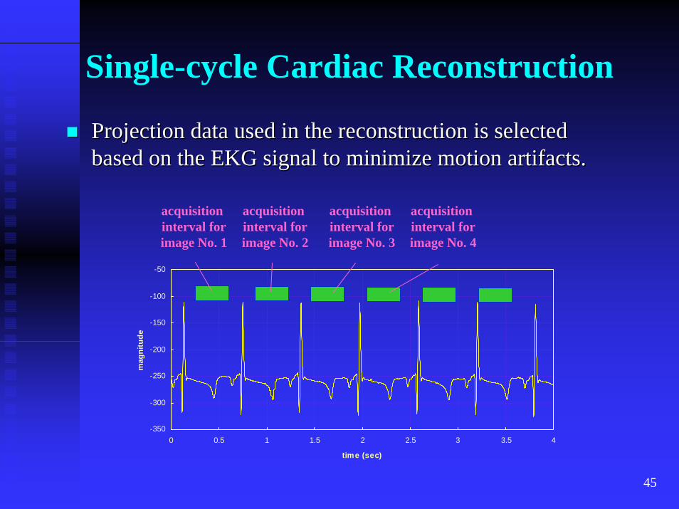
Single-cycle Cardiac Reconstruction
Projection data used in the reconstruction is selected Projection data used in the reconstruction is selected based on the EKG signal to minimize motion artifacts.based on the EKG signal to minimize motion artifacts.
-350
-300
-250
-200
-150
-100
-50
0 0.5 1 1.5 2 2.5 3 3.5 4
time (sec)
mag
nitu
de
acquisition interval forimage No. 1
acquisition interval forimage No. 2
acquisition interval forimage No. 3
acquisition interval forimage No. 4
46
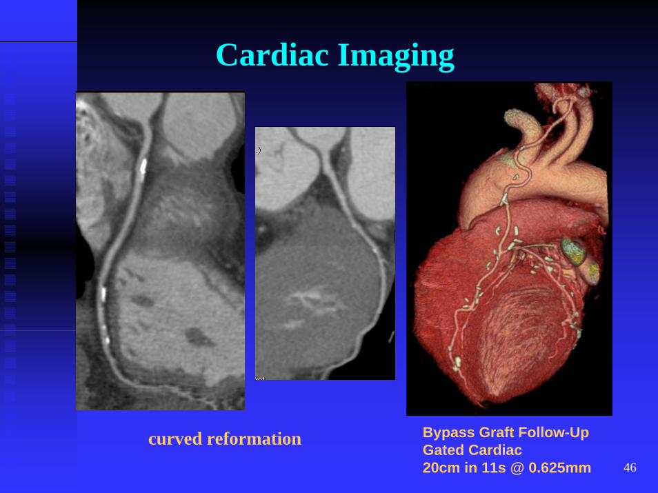
Cardiac Imaging
Bypass Graft Follow-UpGated Cardiac20cm in 11s @ 0.625mm
curved reformation
47
Summary
CT Image reconstruction techniques have been CT Image reconstruction techniques have been continuously developed over the years to match the continuously developed over the years to match the advancement in new acquisition hardware and new advancement in new acquisition hardware and new acquisition techniques.acquisition techniques.
With image explosion from the new CT scanners, With image explosion from the new CT scanners, advanced visualization tools are needed to improve the advanced visualization tools are needed to improve the productivity of radiologists. Faster and better tools are productivity of radiologists. Faster and better tools are constantly developed.constantly developed.
48
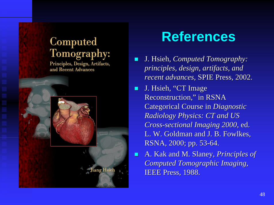
ReferencesJ. Hsieh, J. Hsieh, Computed Tomography: Computed Tomography: principles, design, artifacts, and principles, design, artifacts, and recent advancesrecent advances, SPIE Press, 2002., SPIE Press, 2002.J. Hsieh, “CT Image J. Hsieh, “CT Image Reconstruction,” in RSNA Reconstruction,” in RSNA Categorical Course in Categorical Course in Diagnostic Diagnostic Radiology Physics: CT and US Radiology Physics: CT and US CrossCross--sectional Imaging 2000sectional Imaging 2000, ed. , ed. L. W. Goldman and J. B. L. W. Goldman and J. B. FowlkesFowlkes, , RSNA, 2000; pp. 53RSNA, 2000; pp. 53--64.64.A. A. Kak Kak and M.and M. SlaneySlaney, , Principles of Principles of Computed Computed Tomographic Tomographic ImagingImaging, , IEEE Press, 1988.IEEE Press, 1988.