Embed Size (px)
Citation preview

Cone Beam ComputedTomography Updated
Technology for EndodonticDiagnosisRandolph Todd, DMD
KEYWORDS
� Cone beam computed tomography � Radiographic diagnosis� 3-dimensional radiology � Radiographic outcome assessment� Root canal morphology � Endodontic diagnosis � Apical periodontitis
KEY POINTS
� Narrow field CBCT has many applications in Endodontics and reduces the negative effectsof anatomic noise, geometric distortion and technique sensitivity observed on 2D images.
� Narrow fieldCBCTprovidesearlier detectionof apical periodontitis thanconventional 2D radio-graphs providing improved diagnostic value, treatment efficiency and outcome assessment.
� Narrow field CBCT provides excellent image resolution at reduced radiation exposure ascompared to mid or large field of view CBCT.
� CBCT assists the practitioner to identify canal morphology, numbers of canals and relativepositioning even in the presence of calcific metamorphosis and dystrophic calcifications.
� Identification and treatment of lateral canals is supported by viewing their specific locationwith the use of narrow field of view CBCT before or during endodontic therapy.
INTRODUCTION
According to the Merriam-Webster dictionary, the term “diagnosis” is defined as:“the art or act of identifying a disease from its signs and symptoms.” In the field ofendodontics, dentists review a multitude of signs and symptoms to formulate theirdiagnosis. These include, but are not limited to: sensitivity to heat, sensitivity tocold, percussion, palpation, bite, swelling, caries, periodontal disease, presence of si-nus tracts, and unstimulated pain. In addition to these symptoms, tests are used toidentify variations from normal such as electric pulp tests,1 laser Doppler,2 and radio-graphs3 (first used in 1896 by Otto Walkhoff). In the early 1960s Seltzer and Bender4,5
identified several discrepancies using 2-dimensional (2D) radiographs for observing
Department of Endodontics, Stony Brook University School of Dentistry, Sullivan Hall, StonyBrook, NY 11794, USAE-mail address: [email protected]
Dent Clin N Am 58 (2014) 523–543http://dx.doi.org/10.1016/j.cden.2014.03.003 dental.theclinics.com0011-8532/14/$ – see front matter � 2014 Elsevier Inc. All rights reserved.

Todd524
apical periodontitis (AP). These included: (a) a delayed appearance of radiographic ev-idence of AP until 40% cortical plate demineralization developed and (b) a lack of cor-relation between the size of the histologic defect and AP image.In addition, according to Durack and Patel, 2D radiographs are of limited value due
to the compression of 3-dimensional (3D) structures, geometric distortion, anatomicnoise, and temporal perspectives.4–6
Radiographs are used to identify the changes inside visually opaque objects.Although interpretations of these images are only part of the diagnostic process, thedental community places great emphasis on this information. In the early 1970s, Bry-nolf studied the benefit of using radiographs from multiple angles to increase theirdiagnostic value. She found that using 3 images improved diagnosis significantly.7
Later that decade, grave concerns developed. Many articles published supportedthe idea that reading dental radiographs was too subjective.8–10 To this concern,Orstavik and colleagues12 developed a guide to standardize apical observationscalled the Periapical Index. Despite these efforts, 2D radiographs were still limitedin diagnostic value due to the factors previously listed.4–6
Computer-assisted tomographic imaging or cone beam computed tomography(CBCT), a technology borrowed from medicine, previously focused on the need forbetter surgical guidance during implant placement.14 The principle of ALARA21 (AsLow As Reasonably Achievable) as related to radiation exposure and the lack of res-olution initially limited CBCT use in endodontics.15 A new area of research emerged,and old paradigms were shifting.17 These advances solved many of the listed 2D lim-itations.6,13 Specific applications of this technology developed and the Endodonticcommunity embraced them.18–20
The current narrow field of viewCBCTprovidesa 3D, low-radiation/high-resolution so-lution to many endodontic diagnostic and treatment problems.11 This article will displayspecific case scenarios and supporting literature for the application ofCBCT technology.
ROOTS: ANATOMIC NOISE HIDES ANATOMYCase #1: Maxillary Left First Bicuspid—Diagnosis: Pulpal Necrosis/Symptomatic ApicalPeriodontitis
Identification of root structure, curvature, and location are hampered in 2D radio-graphs by anatomic noise (Fig. 1).6 In this case, CBCT (Figs. 2 and 3) assisted with
Fig. 1. Preoperative 2D periapical x-ray, arrow pointing to hidden radicular anatomy“Anatomic Noise”.

Fig. 2. 3D CBCT sagittal view shows 2 buccal roots (arrow).
Fig. 3. 3D CBCT coronal view shows buccal and palatal roots (arrow).
CBCT Updated Technology for Endodontic Diagnosis 525
the preoperative identification of the presence, location, shape, and lengths of 3separate distinct roots. Note the accurate orientation, size, and location of apicalperiodontitis clearly observed on sagittal (see Fig. 2) and coronal views (seeFig. 3).16 Treatment is clearly supported by preoperative knowledge of rootanatomy.
CANALS: HIDDEN CANAL MORPHOLOGYCase #2: Mandibular Left First Molar, Diagnosis: Irreversible Pulpitis/SymptomaticPeriodontitis
Preoperative identification of the number, location, and length of canals is facilitatedwith a CBCT scan (Figs. 4–7). Successful endodontic treatment depends on treatingall canals (see Fig. 7).22 In tooth #19, a midmesial canal is observed on the preoper-ative axial scan (see Fig. 5) and verified clinically (see Fig. 6).
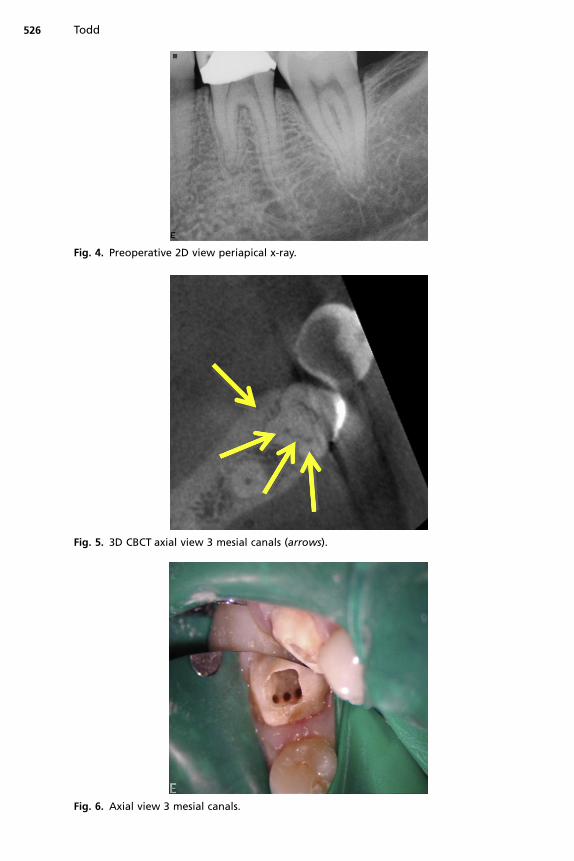
Fig. 5. 3D CBCT axial view 3 mesial canals (arrows).
Fig. 6. Axial view 3 mesial canals.
Fig. 4. Preoperative 2D view periapical x-ray.
Todd526

Fig. 7. Postoperative 2D periapical x-ray 3 mesial canals.
CBCT Updated Technology for Endodontic Diagnosis 527
CALCIFICATIONSCase #3: Maxillary Left Central Incisor Diagnosis—Pulpal Necrosis/Symptomatic ApicalPeriodontitis
Canal obliteration may represent dystrophic calcifications (DC, calcification of degen-erating or necrotic tissue pulp stones23) or calcific metamorphosis (CM, A process ofmineralization after trauma24) (Figs. 8–11). The mechanism for dentin deposition in CMhas been debated by the profession and is still unclear.25,26 It has been suggested thatthe severity of the injury may be related to the rate of deposition.27 The predominance
Fig. 8. Preoperative 2D periapical x-ray, arrow points to calcified root canal.

Fig. 9. 3D CBCT sagittal view, arrow pointing to visible canal.
Todd528
of literature suggests that despite the appearance of CM on a 2D radiograph, a narrowpulp canal space persists (see Figs. 9 and 10).26,28–30 With the development of CBCT,pretreatment identification and location of this narrow pulp space can facilitateminimally invasive treatment.
Fig. 10. Preoperative 3D CBCT axial view, arrow pointing to visible canal.

Fig. 11. Postoperative 2D periapical x-ray minimally invasive treatment.
529
LATERAL CANALSCase #4: Maxillary Left Central Incisor Diagnosis—Pulpal Necrosis/Symptomatic ApicalPeriodontitis
Treatment of lateral canals requires pretreatment knowledge of their presence andlocation (Figs. 12–15).31 2D radiology does not provide adequate information to
Fig. 12. Preoperative 2D periapical x-ray.

Fig. 13. Preoperative 3D CBCT coronal view, arrow pointing to lateral canal exiting intolateral radicular defect.
Fig. 14. 3D CBCT sagittal view provides accurate measurement from apex to lateral canal(distance between arrows).
Todd530

Fig. 15. Postoperative 2D periapical x-ray, guttapercha cone in lateral canal.
CBCT Updated Technology for Endodontic Diagnosis 531
predictably locate and treat this entity.32,33 Successful endodontic treatment dependson the adequate debridement of bacteria from all spaces.31 CBCT technology assiststhe practitioner with identifying the specific location of lateral canals (see Figs. 13 and14). Overcoming the obstacle of identifying and locating lateral canals enhances theability to treat these difficult cases (see Fig. 15).34
BONE MORPHOLOGY IDENTIFIABLE ON CBCTFenestration Case #5
Identification of a fenestration can assist in planning apical surgery (Figs. 16–18).35
CBCT offers the opportunity to accurately evaluate an area of apical periodontitis
Fig. 16. 3D CBCT preoperative sagittal view—isolating buccal plate demonstrating fenestra-tion (arrow pointing to fenestration of Buccal Bone).

Fig. 17. 3D CBCT preoperative reconstructed view buccal plate demonstrating fenestration(arrow pointing to fenestration of buccal bone).
Fig. 18. Apical operative view, demonstrating fenestration observed after flap reflection(arrow pointing to fenestration of buccal bone).
Todd532
for size, volume, and location before surgery.36 Some studies find no value in apicalgrafting, while others advocate that the need for grafting is based on the volume ofthe space to be grafted.37 These studies suggest that larger lesions may not heal suc-cessfully from apical surgery without grafting, due to a lack of clot stability.38 CBCTcan be used to determine the volume of the apical periodontitis lesion. Future researchmay be able to identify the specific volumetric limits for clot stability and graft usage asopposed to the linear measurement currently used.
Dehiscence Case #6
Maxillary left second bicuspid—diagnosis: previously treated root canal/symptomaticapical periodontitis. In case #6 (Figs. 19–22), despite a careful and comprehensive ex-amination and periodontal probing, a vertical root fracture was clinically undetectable.The etiology for endodontic failure was ultimately identified with the use of a CBCT.Isolating the buccal plate defect on a coronal plane view assisted to identify the boneydehiscence (see Fig. 21). In this case, the vertical fracture was verified during the sur-gical exposure (see Fig. 22). Vertical fractures and cracks may not be visible on 3D

Fig. 19. Preoperative 2D periapical x-ray #13.
Fig. 20. 3D CBCT axial view (arrow pointing to buccal bone defect over vertical fracture).
Fig. 21. 3D CBCT sagittal view (arrows pointing to buccal bone dehiscence). The fracturemay not be visible on CBCT; look for the adjacent bone loss (arrows).
CBCT Updated Technology for Endodontic Diagnosis 533

Fig. 22. Surgical exposure of fracture and dehiscence (arrows). The fracture may not bevisible on CBCT; look for the adjacent bone loss (arrows).
Todd534
images. The Nyquest Theorem identifies the limitation of an image’s ability to identify acrack or fracture defect to equal twice the voxel size used to scan the object.39
IDENTIFYING CYSTS
A radicular cyst is a common odontogenic lesion of inflammatory origin. The ability todistinguish a cyst from a granuloma has been studied over the years.40–45 Variousstudies have suggested that the presence of an opaque lamina provides evidenceof a cyst. A study by Ricucci and colleagues46 refutes this theory. In support, oneonly needs to return to the findings of Seltzer, Bender, Bhaskar47 and more recentlyby Lalonde,40 to see that cysts, granulomas, and abscess all have a similar appear-ance on 2D radiographs. Conflicting studies have been published debating CBCT’seffectiveness to distinguish cysts from granulomas.48 In the following examples, oneobserves the lumen of the cyst42 as detected on CBCT (Figs. 23 and 24) but not visible
Fig. 23. 3D CBCT coronal view of apical periodontitis #5 with cystic lumen (arrow pointing toblack cystic lumen within gray apical defect).

Fig. 24. 3D CBCT sagittal view of apical periodontitis #5 with cystic lumen (arrow pointing toblack cystic lumen within gray apical defect).
Fig. 25. Threeviewsofan incisive canal cyst. (Data from Faitaroni LA,BuenoMR,CarvalhosaAA,et al. Differential diagnosis of apical periodontitis and nasopalatine duct cyst. J Endod2011;37(3):403–10.)
CBCT Updated Technology for Endodontic Diagnosis 535
on preoperative 2D image (Fig. 26). The question remains, however; if the lumen is notvisible, is it a granuloma? Further research is needed to clarify this issue.Case #7 Diagnosis: incisive canal cyst (Fig. 25).Case #8 Maxillary right first bicuspid—diagnosis: pulpal necrosis/asymptomatic
apical periodontitis radicular cyst (see Figs. 23, 24 and 26).
Fig. 26. Preoperative 2D image of apical periodontitis #5.

Todd536
Endodontic Recall
Endodontic healing has traditionally been verified clinically and radiographically. TheAAE 2005 definitions are described in Box 1.
Box 1
Definitions of endodontic outcomes
Healed—functional, asymptomatic teeth with no or minimal radiographicperiradicularpathosis
Nonhealed—nonfunctional, symptomatic teeth with or without radiographicperiradicularpathosis
Healing—teeth with radiographic periradicularpathosis, which are asymptomatic andfunctional, or teeth with or without radiographic periradicularpathosis, which aresymptomatic but whose intended function is not altered
Functional—a treated tooth or root that is serving its intended purpose in the dentition
Modified from Ingles’s Endodontics 6, chapter 32. Friedman S, editor. Treatment outcome: Thepotential for healing and retained function. p. 1162–232.
The outcome of endodontically treated teeth is heavily weighted on the observationof radiographic healing. The low predictive value49 of 2D radiography limits its useful-ness for evaluation of repair. 3D imaging expands the function of the recall examina-tion to include all periradicular tissues (cortical and medullary bone). The subsequentexamples apply current CBCT technology to discover the true status of all periradic-ular tissues.50 2D radiographs may indicate buccal or lingual plate healing but canmask the periradicular status. As noted by Orstavik, healing may take 1 to 4 years.45
Case #9: Healing—Diagnosis: Previously Treated Root Canal/Asymptomatic ApicalPeriodontitis
Nonsurgical retreatment was completed in 2 visits with Ca(OH)2 used as intravisitmedicament (Figs. 27 and 28). Patient returned for a 1-year routine recall (Fig. 29),asymptomatic. 2D radiographic examination revealed healed apex, while the 3Dradiograph (Fig. 30) exhibited possible reduction is size of asymptomatic apical peri-odontitis when compared with 3D preoperative images (see Fig. 28).
Fig. 27. Pre-operative 2D periapical x-ray.

Fig. 28. Pre-operative 3D.
Fig. 29. 1 year recall 2D periapical x-ray.
Fig. 30. 1 year recall 3D.
CBCT Updated Technology for Endodontic Diagnosis 537
Case #10: Healed—Diagnosis: Previous Root Canal Treatment (Missed Mesiobuccal)/Symptomatic Apical Periodontitis
Nonsurgical retreatment was completed in 2 visits (Figs. 31 and 32), with Ca(OH)2used as intravisit medicament. The patient returned 3 years after retreatment with

Fig. 31. Preoperative 2D periapical x-ray, 7/27/09.
Fig. 32. Postoperative 2D periapical x-ray, 8/27/09.
538 Todd
continuous evidence of apical periodontitis on 2D radiograph. Surgical intervention(apicoectomy) was performed. One year and 18 months later, 2D (Figs. 33 and 34)and 3D screen shots exhibited healing of periradicular tissues.
Fig. 33. 1 year recall 2D periapical x-ray apicoectomy.
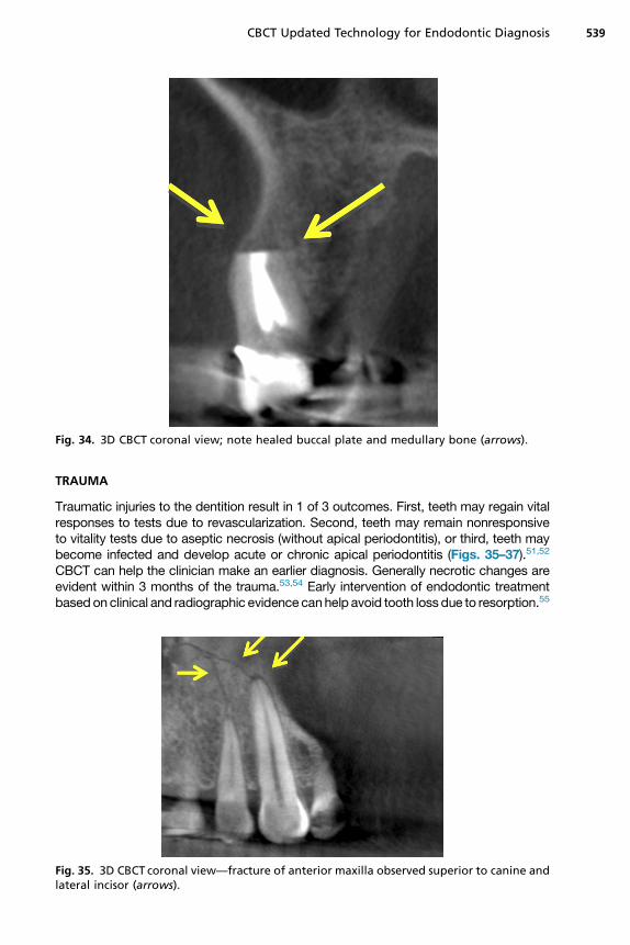
Fig. 34. 3D CBCT coronal view; note healed buccal plate and medullary bone (arrows).
CBCT Updated Technology for Endodontic Diagnosis 539
TRAUMA
Traumatic injuries to the dentition result in 1 of 3 outcomes. First, teeth may regain vitalresponses to tests due to revascularization. Second, teeth may remain nonresponsiveto vitality tests due to aseptic necrosis (without apical periodontitis), or third, teeth maybecome infected and develop acute or chronic apical periodontitis (Figs. 35–37).51,52
CBCT can help the clinician make an earlier diagnosis. Generally necrotic changes areevident within 3 months of the trauma.53,54 Early intervention of endodontic treatmentbased on clinical and radiographic evidence canhelp avoid tooth loss due to resorption.55
Fig. 35. 3D CBCT coronal view—fracture of anterior maxilla observed superior to canine andlateral incisor (arrows).

Fig. 36. 3D CBCT sagittal view of horizontal root fracture (arrows).
Fig. 37. 3D CBCT rendering of horizontal root fracture (arrow).
Todd540
Osseous Trauma: Case #11
A 45-year-old woman was hit in the face by a bus mirror and sustained a maxillaryfracture, avulsions and luxations of multiple teeth (see Figs. 35–37). The CBCT wasused to identify components of the maxillary fracture’s location andmorphology, ridgedefect height and width, and imaging of the temporomandibular joints.56,57
CONCLUSIONS
The previous examples identify the value of CBCT for Endodontics. Narrow fieldof view CBCT facilitates diagnosis, treatment and outcome assessment whileadhering to ALARA principles. Additional applications for this technology can be

CBCT Updated Technology for Endodontic Diagnosis 541
expected within the Endodontic field as a result of the explosion of research in theimaging field.
REFERENCES
1. Burrill DY. Pulp testing by determination of fusion frequency. J Dent Res 1962;41:437–45.
2. Gazelius B, Olgart L, Edwall B, et al. Non-invasive recording of blood flow inhuman dental pulp. Endod Dent Traumatol 1986;2(5):219–21.
3. Ruprecht A. When was the first dental radiograph taken on human? In: Sci-ence, Inventions The first dental radiograph was taken in January 1896 byOtto Walkhoff, D.D.S., M.D., in Brunswick, Germany, a few days after WilhelmRoentgen published about his discovery of x-rays. Walkhoff placed a smallphotographic plate wrapped in rubberdam in his mouth and subjected himselfto 25 minutes of x-ray exposure. Exposure times today are in the range of 0.01–0.03 seconds. The Journal of the American Dental Association 2008;139:55–65.
4. Bender IB, Seltzer S. Roentgenographic and direct observation of experimentallesions in bone: I. 1961. J Endod 2003;29(11):702–6 [discussion: 701].
5. Bender IB, Seltzer S. Roentgenographic and direct observation of experimentallesions in bone: II. 1961. J Endod 2003;29(11):707–12 [discussion: 701].
6. Durack C, Patel S. Cone beam computed tomography in endodontics. BrazDent J 2012;23(3):179–91.
7. Brynolf I. Radiography of the periapical region as a diagnostic aid. I. Diagnosisof marginal changes. Dent Radiogr Photogr 1978;51(2):21–39.
8. Goldman M, Pearson AH, Darzenta N. Reliability of radiographic interpretations.Oral Surg Oral Med Oral Pathol 1974;38(2):287–93.
9. Goldman M, Pearson AH, Darzenta N. Endodontic success–who’s reading theradiograph? Oral Surg Oral Med Oral Pathol 1972;33(3):432–7.
10. Valachovic RW, Douglass CW, Berkey CS, et al. Examiner reliability in dentalradiography. J Dent Res 1986;65(3):432–6.
11. Estrela C, Bueno MR, Leles CR, et al. Accuracy of cone beam computed tomog-raphy and panoramic and periapical radiography for detection of apical peri-odontitis. J Endod 2008;34(3):273–9.
12. Orstavik D, Kerekes K, Eriksen HM. The periapical index: a scoring system forradiographic assessment of apical periodontitis. Endod Dent Traumatol 1986;2(1):20–34.
13. Scarfe WC, Farman AG. What is cone-beam CTand how does it work? Dent ClinNorth Am 2008;52(4):707–30.
14. Mozzo P, Procacci C, Tacconi A, et al. A new volumetric CT machine for dentalimaging based on the cone-beam technique: preliminary results. Eur Radiol1998;8(9):1558–64.
15. Farman AG, Scarfe WC. Development of imaging selection criteria and proce-dures should precede cephalometric assessment with cone-beam computedtomography. Am J Orthod Dentofacial Orthop 2006;130(2):257–65.
16. Ha, Dan-Linh. Accuracy of limited field cone beam computed tomography in thedetection of buccal cortical plate perforations due to periapical lesions. 2013.Available at: http://hdl.handle.net/10156/4225. Accessed May 9, 2013.
17. Hashimoto K, Arai Y, Iwai K, et al. A comparison of a new limited cone beamcomputed tomography machine for dental use with a multidetector row helicalCT machine. Oral Surg Oral Med Oral Pathol Oral Radiol Endod 2003;95(3):371–7.

Todd542
18. American Association of Endodontists. Endodontics colleagues for excellences:cone beam-computed tomography. Chicago: American Association of Endodon-tists; 2011.
19. Patel S, Dawood A, Pitt Ford T, et al. The potential applications of cone beamcomputed tomography in the management of endodontic problems. Int EndodJ 2007;40:818–30.
20. Cotton TP, Geisler TM, Holden DT, et al. Endodontic applications of cone beamvolumetric tomography. J Endod 2007;33:1121–32.
21. Farman AG. ALARA still applies. Oral Surg Oral Med Oral Pathol Oral RadiolEndod 2005;100:395–7.
22. Siqueira JF Jr. Aetiology of root canal treatment failure: why well-treated teethcan fail. Int Endod J 2001;34:1–10.
23. Wakabayashi H, Horikawa M, Funato A, et al. Bio-microscopical observation ofdystrophic calcification induced by calcium hydroxide. Endod Dent Traumatol1993;9(4):165–70.
24. Amir FA, Gutmann JL, Witherspoon DE. Calcific metamorphosis: a challenge inendodontic diagnosis and treatment. Quintessence Int 2001;32(6):447–55.
25. Andreasen J. Luxation of permanent teeth due to trauma. Scand J Dent Res1970;78:273–86.
26. Torneck C. The clinical significance and management of calcific pulp oblitera-tion. Alpha Omegan 1990;83:50–4.
27. Ten Cate AR. Oral histology: development, structure, and function. 5th edition.St Louis (MO): Mosby; 1998.
28. Holcomb J, Gregory W. Calcific metamorphosis of the pulp: its incidence andtreatment. Oral Surg Oral Med Oral Pathol 1967;24:825–30.
29. Schindler WG, Gullickson DC. Rationale for the management of calcific meta-morphosis secondary to traumatic injuries. J Endod 1988;14:408–12.
30. Smith J. Calcific metamorphosis: a treatment dilemma. Oral Surg Oral Med OralPathol 1982;54:441–4.
31. Ricucci D, Siqueira JF Jr. Fate of the tissue in lateral canals and apical ramifica-tions in response to pathologic conditions and treatment procedures. J Endod2010;36(1):1–15.
32. De Deus QD. Frequency, location, and direction of the lateral, secondary, andaccessory canals. J Endod 1975;1:361–6.
33. Vertucci FJ. Root canal anatomy of the human permanent teeth. Oral Surg OralMed Oral Pathol 1984;58:589–99.
34. Weine FS. The enigma of the lateral canal. Dent Clin North Am 1984;28:833–52.35. Scarfe WC, Levin MD, Gane D, et al. The use of cone beam computed tomog-
raphy in endodontics. Int J Dent 2009;2009:634567.36. Suebnukarn S, Rhienmora P, Haddawy P. The use of cone-beam computed
tomography and virtual reality simulation for pre-surgical practice in endodonticmicrosurgery. Int Endod J 2012;45(7):627–32.
37. Sreedevi PV, Varghese NO, Varugheese JM. Prognosis of periapical surgeryusing bonegrafts: a clinical study. J Conserv Dent 2011;14(1):68–72.
38. Dudek D, So1tykiewicz K, Helewski K, et al. Treatment of a mandibular cyst withsynthetic bone graft substitute. Implants 1 2013;34–36.
39. Wang P, Yan XB, Lui DG, et al. Detection of dental root fractures by using cone-beam computed tomography. Dentomaxillofac Radiol 2011;40:290–8.
40. Lalonde ER, Luebke RG. The frequency and distribution of periapical cysts andgranulomas: an evaluation of 800 specimens. Oral Surg Oral Med Oral Pathol1968;25(6):861–8.

CBCT Updated Technology for Endodontic Diagnosis 543
41. Kuc I, Peters E, Pan J. Comparison of clinical and histologic diagnoses in periap-ical lesions. Oral SurgOral MedOral Pathol Oral Radiol Endod 2000;89(3):333–7.
42. Rosenberg PA, Frisbie J, Lee J, et al. Evaluation of pathologists (histopathology)and radiologists (cone beam computed tomography) differentiating radicularcysts from granulomas. J Endod 2010;36(3):423–8.
43. Shrout MK, Hall JM, Hildebolt CE. Differentiation of periapical granulomas andradicular cysts by digital radiometric analysis. Oral Surg Oral Med Oral Pathol1993;76(3):356–61.
44. White SC, Sapp JP, Seto BG, et al. Absence of radiometric differentiationbetween periapical cysts and granulomas. Oral Surg Oral Med Oral Pathol1994;78(5):650–4.
45. Orstavik D. Time-course and risk analyses of the development and healing ofchronic apical periodontitis in man. Int Endod J 1996;29(3):150–5.
46. Ricucci D, Mannocci F, Ford TR. A study of periapical lesions correlating thepresence of a radiopaque lamina with histological findings. Oral Surg OralMed Oral Pathol Oral Radiol Endod 2006;101(3):389–94.
47. Bhaskar SN. Periapical lesions—types, incidence, and clinical features. OralSurg Oral Med Oral Pathol 1966;21(5):657–71.
48. Trope M, Pettigrew J, Petras J, et al. Differentiation of radicular cyst and granu-lomas using computerized tomography. Endod Dent Traumatol 1989;5(2):69–72.
49. Peters CI, Peters OA. Cone beam computed tomography and other imagingtechniques in the determination of periapical healing. Endod Top 2012;26(1):57–75.
50. Khetarpal A, Chaudhary S, Sahai S, et al. Radiological assessment of periapicalhealing using the cone beam computed tomography periapical index: casereport. IOSR Journal of Dental and Medical Sciences 2013;9(5):46–51.
51. Jacobsen I. Criteria for diagnosis of pulp necrosis in traumatized permanent in-cisors. Scand J Dent Res 1980;88(4):306–12.
52. Sundqvist G. Bacteriological studies of necrotic dental pulps. Department ofOral Microbiology, University of Umea; 1976. p. 94.
53. Andreasen FM, Pedersen BV. Prognosis of luxated permanent teeth — thedevelopment of pulp necrosis. Endod Dent Traumatol 1985;1:207–20.
54. Jacobsen I, Kerekes K. Diagnosis and treatment of pulp necrosis in permanentanterior teeth with root fracture. Scand J Dent Res 1980;88(5):370–6.
55. Andreasen JO, Andreasen FM. Root resorption following traumatic dentalinjuries. Proc Finn Dent Soc 1992;88(Suppl 1):95–114.
56. Palomo L, Palomo JM. Cone beam CT for diagnosis and treatment planning intrauma cases. Dent Clin North Am 2009;53:717–27.
57. _Ilguy D, _Ilguy M, Fisekcioglu E, et al. Detection of jaw and root fractures usingcone beam computed tomography: a case report. Dentomaxillofac Radiol2009;38:169–73.