Embed Size (px)
Citation preview
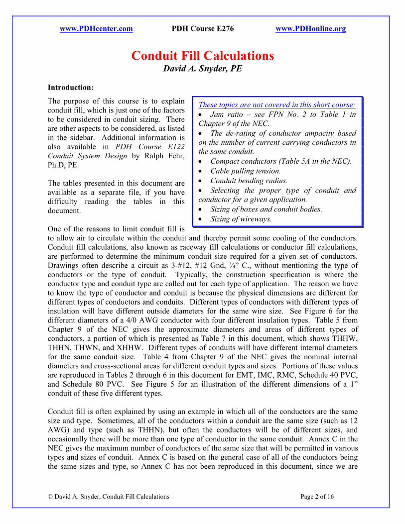
PDHonline Course E276 (2 PDH)
Conduit Fill Calculations
2012
Instructor: David A. Snyder, PE
PDH Online | PDH Center5272 Meadow Estates Drive
Fairfax, VA 22030-6658Phone & Fax: 703-988-0088
www.PDHonline.orgwww.PDHcenter.com
An Approved Continuing Education Provider
www.PDHcenter.com PDH Course E276 www.PDHonline.org
Conduit Fill Calculations David A. Snyder, PE
Introduction:
The purpose of this course is to explain conduit fill, which is just one of the factors to be considered in conduit sizing. There are other aspects to be considered, as listed in the sidebar. Additional information is also available in PDH Course E122 Conduit System Design by Ralph Fehr, Ph.D, PE. The tables presented in this document are available as a separate file, if you have difficulty reading the tables in this document. One of the reasons to limit conduit fill is to allow air to circulate within the conduit and thereby permit some cooling of the conductors. Conduit fill calculations, also known as raceway fill calculations or conductor fill calculations, are performed to determine the minimum conduit size required for a given set of conductors. Drawings often describe a circuit as 3-#12, #12 Gnd, ¾” C., without mentioning the type of conductors or the type of conduit. Typically, the construction specification is where the conductor type and conduit type are called out for each type of application. The reason we have to know the type of conductor and conduit is because the physical dimensions are different for different types of conductors and conduits. Different types of conductors with different types of insulation will have different outside diameters for the same wire size. See Figure 6 for the different diameters of a 4/0 AWG conductor with four different insulation types. Table 5 from Chapter 9 of the NEC gives the approximate diameters and areas of different types of conductors, a portion of which is presented as Table 7 in this document, which shows THHW, THHN, THWN, and XHHW. Different types of conduits will have different internal diameters for the same conduit size. Table 4 from Chapter 9 of the NEC gives the nominal internal diameters and cross-sectional areas for different conduit types and sizes. Portions of these values are reproduced in Tables 2 through 6 in this document for EMT, IMC, RMC, Schedule 40 PVC, and Schedule 80 PVC. See Figure 5 for an illustration of the different dimensions of a 1” conduit of these five different types. Conduit fill is often explained by using an example in which all of the conductors are the same size and type. Sometimes, all of the conductors within a conduit are the same size (such as 12 AWG) and type (such as THHN), but often the conductors will be of different sizes, and occasionally there will be more than one type of conductor in the same conduit. Annex C in the NEC gives the maximum number of conductors of the same size that will be permitted in various types and sizes of conduit. Annex C is based on the general case of all of the conductors being the same sizes and type, so Annex C has not been reproduced in this document, since we are
© David A. Snyder, Conduit Fill Calculations Page 2 of 16
These topics are not covered in this short course: • Jam ratio – see FPN No. 2 to Table 1 in Chapter 9 of the NEC. • The de-rating of conductor ampacity based on the number of current-carrying conductors in the same conduit. • Compact conductors (Table 5A in the NEC). • Cable pulling tension. • Conduit bending radius. • Selecting the proper type of conduit and conductor for a given application. • Sizing of boxes and conduit bodies. • Sizing of wireways.
www.PDHcenter.com PDH Course E276 www.PDHonline.org
considering specific cases in which the conductors might be different sizes and types. You can use the techniques from this course to verify the values shown in Annex C, but be sure to consider Note 7 to the tables in Chapter 9 of the NEC, as explained later. Occasionally, a circuit will run through more than one type of conduit. A common example of this is a circuit that runs in galvanized rigid steel (GRS, sometimes called RGS) above grade, then transitions to Schedule 40 PVC below grade, then back into GRS when it comes above grade again. The conduit fill calculations would be slightly different for the two types of conduit. Conduit fill calculations are relatively simple and straightforward, but certain details must be known about the conduit and the conductors. There can be only one unknown from the following five pieces of information in order to perform the calculations to match the conduit size with the conductors:
Size of conduit, such as 3”
Type of conduit, such as Schedule 40 PVC
Conductor quantities, such as 3-#12 THWN
Conductor sizes, such as 3-#12 THWN
Conductor types, such as 3-#12 THWN. For multiconductor cables, the last two topics listed above are replaced by using the overall or outside diameter of the cable (it doesn’t matter what the sizes and types of the internal conductors are). This document will use different formats interchangeably to describe conductor sizes, such as #12 and 12 AWG. With regard to formulas and calculations in this document, we will be using the asterisk (*) for multiplication and the forward slash (/) for division. Since we will be discussing diameter (d), rather than radius (r), in this document, the familiar expression for the area of a circle will be shown as A = π * d2 / 4, rather than A = π * r2. Conduit Fill Tables from the NEC:
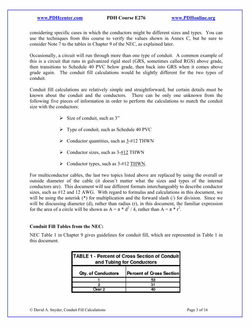
NEC Table 1 in Chapter 9 gives guidelines for conduit fill, which are represented in Table 1 in this document.
© David A. Snyder, Conduit Fill Calculations Page 3 of 16
www.PDHcenter.com PDH Course E276 www.PDHonline.org
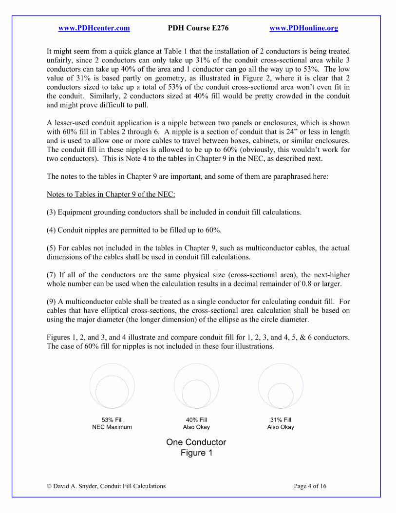
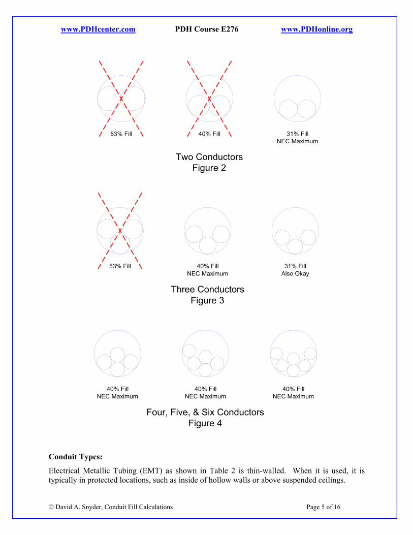
It might seem from a quick glance at Table 1 that the installation of 2 conductors is being treated unfairly, since 2 conductors can only take up 31% of the conduit cross-sectional area while 3 conductors can take up 40% of the area and 1 conductor can go all the way up to 53%. The low value of 31% is based partly on geometry, as illustrated in Figure 2, where it is clear that 2 conductors sized to take up a total of 53% of the conduit cross-sectional area won’t even fit in the conduit. Similarly, 2 conductors sized at 40% fill would be pretty crowded in the conduit and might prove difficult to pull. A lesser-used conduit application is a nipple between two panels or enclosures, which is shown with 60% fill in Tables 2 through 6. A nipple is a section of conduit that is 24” or less in length and is used to allow one or more cables to travel between boxes, cabinets, or similar enclosures. The conduit fill in these nipples is allowed to be up to 60% (obviously, this wouldn’t work for two conductors). This is Note 4 to the tables in Chapter 9 in the NEC, as described next. The notes to the tables in Chapter 9 are important, and some of them are paraphrased here: Notes to Tables in Chapter 9 of the NEC: (3) Equipment grounding conductors shall be included in conduit fill calculations. (4) Conduit nipples are permitted to be filled up to 60%. (5) For cables not included in the tables in Chapter 9, such as multiconductor cables, the actual dimensions of the cables shall be used in conduit fill calculations. (7) If all of the conductors are the same physical size (cross-sectional area), the next-higher whole number can be used when the calculation results in a decimal remainder of 0.8 or larger. (9) A multiconductor cable shall be treated as a single conductor for calculating conduit fill. For cables that have elliptical cross-sections, the cross-sectional area calculation shall be based on using the major diameter (the longer dimension) of the ellipse as the circle diameter. Figures 1, 2, and 3, and 4 illustrate and compare conduit fill for 1, 2, 3, and 4, 5, & 6 conductors. The case of 60% fill for nipples is not included in these four illustrations.
© David A. Snyder, Conduit Fill Calculations Page 4 of 16
One ConductorFigure 1
40% FillAlso Okay
53% FillNEC Maximum
31% FillAlso Okay
www.PDHcenter.com PDH Course E276 www.PDHonline.org
Two ConductorsFigure 2
40% Fill53% Fill 31% FillNEC Maximum
40% FillNEC Maximum
53% Fill 31% FillAlso Okay
Three ConductorsFigure 3
40% FillNEC Maximum
Four, Five, & Six ConductorsFigure 4
40% FillNEC Maximum
40% FillNEC Maximum
Conduit Types:
© David A. Snyder, Conduit Fill Calculations Page 5 of 16
Electrical Metallic Tubing (EMT) as shown in Table 2 is thin-walled. When it is used, it is typically in protected locations, such as inside of hollow walls or above suspended ceilings.
www.PDHcenter.com PDH Course E276 www.PDHonline.org
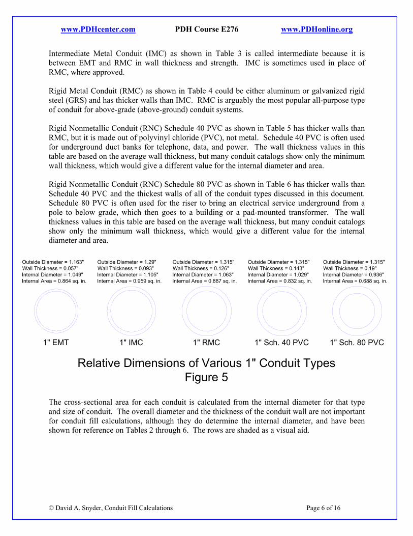
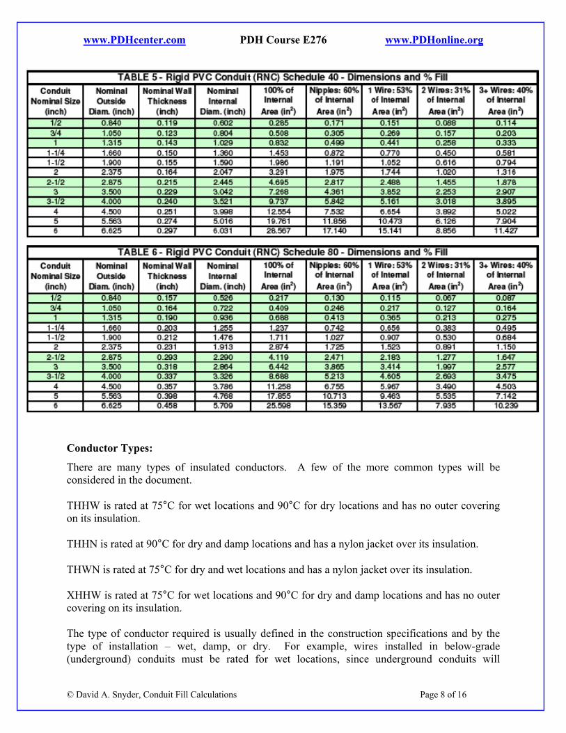
Intermediate Metal Conduit (IMC) as shown in Table 3 is called intermediate because it is between EMT and RMC in wall thickness and strength. IMC is sometimes used in place of RMC, where approved. Rigid Metal Conduit (RMC) as shown in Table 4 could be either aluminum or galvanized rigid steel (GRS) and has thicker walls than IMC. RMC is arguably the most popular all-purpose type of conduit for above-grade (above-ground) conduit systems. Rigid Nonmetallic Conduit (RNC) Schedule 40 PVC as shown in Table 5 has thicker walls than RMC, but it is made out of polyvinyl chloride (PVC), not metal. Schedule 40 PVC is often used for underground duct banks for telephone, data, and power. The wall thickness values in this table are based on the average wall thickness, but many conduit catalogs show only the minimum wall thickness, which would give a different value for the internal diameter and area. Rigid Nonmetallic Conduit (RNC) Schedule 80 PVC as shown in Table 6 has thicker walls than Schedule 40 PVC and the thickest walls of all of the conduit types discussed in this document. Schedule 80 PVC is often used for the riser to bring an electrical service underground from a pole to below grade, which then goes to a building or a pad-mounted transformer. The wall thickness values in this table are based on the average wall thickness, but many conduit catalogs show only the minimum wall thickness, which would give a different value for the internal diameter and area.
1" IMC
Relative Dimensions of Various 1" Conduit TypesFigure 5
Outside Diameter = 1.29"Wall Thickness = 0.093"Internal Diameter = 1.105"Internal Area = 0.959 sq. in.
1" EMT
Outside Diameter = 1.163"Wall Thickness = 0.057"Internal Diameter = 1.049"Internal Area = 0.864 sq. in.
1" RMC
Outside Diameter = 1.315"Wall Thickness = 0.126"Internal Diameter = 1.063"Internal Area = 0.887 sq. in.
1" Sch. 40 PVC
Outside Diameter = 1.315"Wall Thickness = 0.143"Internal Diameter = 1.029"Internal Area = 0.832 sq. in.
1" Sch. 80 PVC
Outside Diameter = 1.315"Wall Thickness = 0.19"Internal Diameter = 0.936"Internal Area = 0.688 sq. in.
© David A. Snyder, Conduit Fill Calculations Page 6 of 16
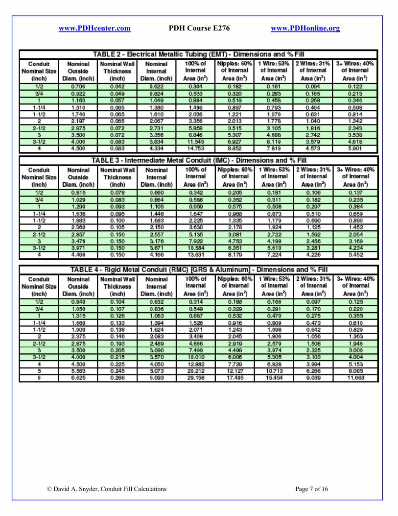
The cross-sectional area for each conduit is calculated from the internal diameter for that type and size of conduit. The overall diameter and the thickness of the conduit wall are not important for conduit fill calculations, although they do determine the internal diameter, and have been shown for reference on Tables 2 through 6. The rows are shaded as a visual aid.
www.PDHcenter.com PDH Course E276 www.PDHonline.org
© David A. Snyder, Conduit Fill Calculations Page 7 of 16
www.PDHcenter.com PDH Course E276 www.PDHonline.org
Conductor Types:
There are many types of insulated conductors. A few of the more common types will be considered in the document. THHW is rated at 75°C for wet locations and 90°C for dry locations and has no outer covering on its insulation. THHN is rated at 90°C for dry and damp locations and has a nylon jacket over its insulation. THWN is rated at 75°C for dry and wet locations and has a nylon jacket over its insulation. XHHW is rated at 75°C for wet locations and 90°C for dry and damp locations and has no outer covering on its insulation.
© David A. Snyder, Conduit Fill Calculations Page 8 of 16
The type of conductor required is usually defined in the construction specifications and by the type of installation – wet, damp, or dry. For example, wires installed in below-grade (underground) conduits must be rated for wet locations, since underground conduits will
www.PDHcenter.com PDH Course E276 www.PDHonline.org
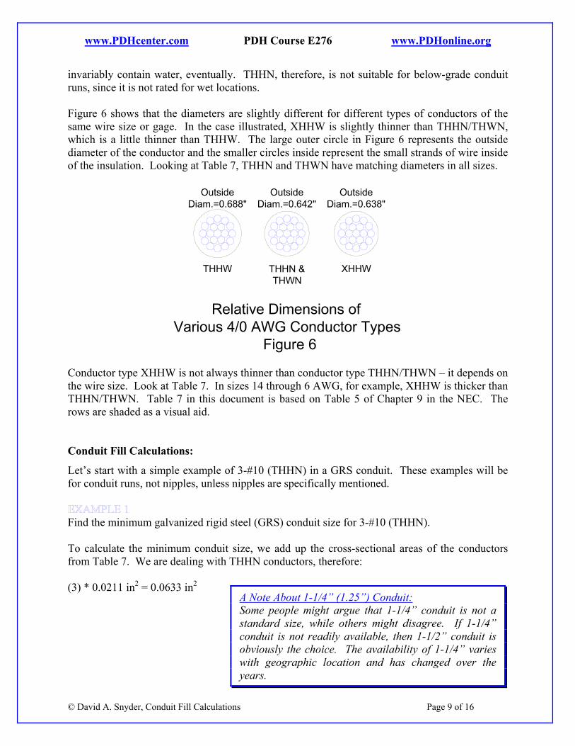
invariably contain water, eventually. THHN, therefore, is not suitable for below-grade conduit runs, since it is not rated for wet locations. Figure 6 shows that the diameters are slightly different for different types of conductors of the same wire size or gage. In the case illustrated, XHHW is slightly thinner than THHN/THWN, which is a little thinner than THHW. The large outer circle in Figure 6 represents the outside diameter of the conductor and the smaller circles inside represent the small strands of wire inside of the insulation. Looking at Table 7, THHN and THWN have matching diameters in all sizes.
Relative Dimensions ofVarious 4/0 AWG Conductor Types
Figure 6
XHHWTHHN &THWN
THHW
OutsideDiam.=0.638"
OutsideDiam.=0.642"
OutsideDiam.=0.688"
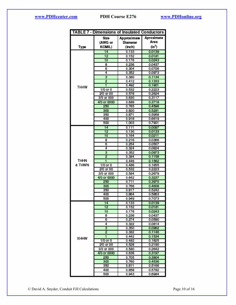
Conductor type XHHW is not always thinner than conductor type THHN/THWN – it depends on the wire size. Look at Table 7. In sizes 14 through 6 AWG, for example, XHHW is thicker than THHN/THWN. Table 7 in this document is based on Table 5 of Chapter 9 in the NEC. The rows are shaded as a visual aid. Conduit Fill Calculations:
Let’s start with a simple example of 3-#10 (THHN) in a GRS conduit. These examples will be for conduit runs, not nipples, unless nipples are specifically mentioned.
Find the minimum galvanized rigid steel (GRS) conduit size for 3-#10 (THHN). To calculate the minimum conduit size, we add up the cross-sectional areas of the conductors from Table 7. We are dealing with THHN conductors, therefore: (3) * 0.0211 in2 = 0.0633 in2
© David A. Snyder, Conduit Fill Calculations Page 9 of 16
A Note About 1-1/4” (1.25”) Conduit: Some people might argue that 1-1/4” conduit is not a standard size, while others might disagree. If 1-1/4” conduit is not readily available, then 1-1/2” conduit is obviously the choice. The availability of 1-1/4” varies with geographic location and has changed over the years.
www.PDHcenter.com PDH Course E276 www.PDHonline.org
© David A. Snyder, Conduit Fill Calculations Page 10 of 16
www.PDHcenter.com PDH Course E276 www.PDHonline.org
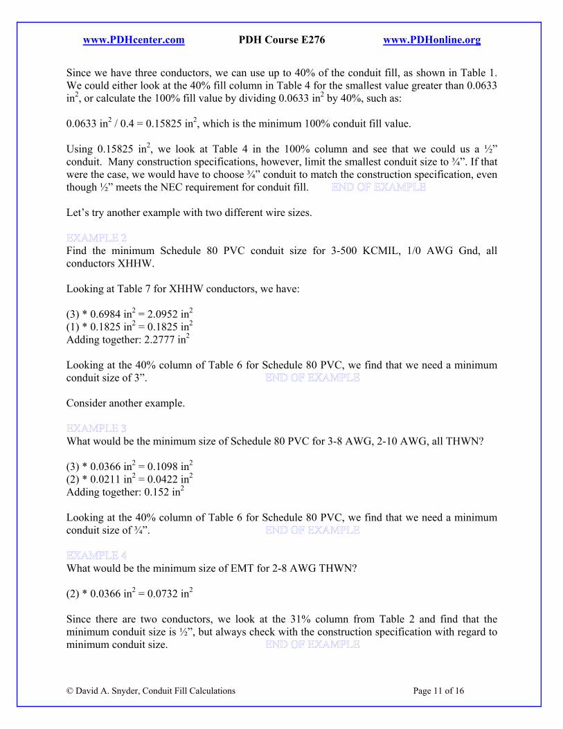
Since we have three conductors, we can use up to 40% of the conduit fill, as shown in Table 1. We could either look at the 40% fill column in Table 4 for the smallest value greater than 0.0633 in2, or calculate the 100% fill value by dividing 0.0633 in2 by 40%, such as: 0.0633 in2 / 0.4 = 0.15825 in2, which is the minimum 100% conduit fill value. Using 0.15825 in2, we look at Table 4 in the 100% column and see that we could us a ½” conduit. Many construction specifications, however, limit the smallest conduit size to ¾”. If that were the case, we would have to choose ¾” conduit to match the construction specification, even though ½” meets the NEC requirement for conduit fill. Let’s try another example with two different wire sizes.
Find the minimum Schedule 80 PVC conduit size for 3-500 KCMIL, 1/0 AWG Gnd, all conductors XHHW. Looking at Table 7 for XHHW conductors, we have: (3) * 0.6984 in2 = 2.0952 in2
(1) * 0.1825 in2 = 0.1825 in2
Adding together: 2.2777 in2
Looking at the 40% column of Table 6 for Schedule 80 PVC, we find that we need a minimum conduit size of 3”. Consider another example.
What would be the minimum size of Schedule 80 PVC for 3-8 AWG, 2-10 AWG, all THWN? (3) * 0.0366 in2 = 0.1098 in2
(2) * 0.0211 in2 = 0.0422 in2
Adding together: 0.152 in2
Looking at the 40% column of Table 6 for Schedule 80 PVC, we find that we need a minimum conduit size of ¾”.
What would be the minimum size of EMT for 2-8 AWG THWN? (2) * 0.0366 in2 = 0.0732 in2
© David A. Snyder, Conduit Fill Calculations Page 11 of 16
Since there are two conductors, we look at the 31% column from Table 2 and find that the minimum conduit size is ½”, but always check with the construction specification with regard to minimum conduit size.
www.PDHcenter.com PDH Course E276 www.PDHonline.org
What would be the minimum size of Schedule 40 PVC for one 3/0 AWG ground XHHW? The overall area for an XHHW 3/0 AWG conductor is 0.2642 in2. Looking at the 53% column in Table 5 for Schedule 40 PVC, we find that we need a minimum conduit size of ¾”.
What would be the minimum size of Schedule 40 PVC for 5-3/0 AWG XHHW? (5) * 0.2642 in2 = 1.321 in2
Look at the 40% column of Table 5. Does this mean that we have to go up to 2-1/2” Sch. 40 conduit, since 2” Sch. 40 conduit only provides 1.316 in2? Since all of the conductors are the same physical size, we might be able to use Note 7 to the tables in Chapter 9 of the NEC, which says we can round up the number of conductors permitted if we come up with a decimal remainder of 0.8 or more. Therefore, looking at 2”: 1.316 in2 / 0.2642 in2 = 4.98 conductors Note 7 says we can round this value up to 5 conductors, so 2” Schedule 40 PVC conduit would meet the NEC requirements for conduit fill. Would the outcome of the above example be the same for Schedule 80 PVC?
The 40% column of Table 6 for 2” Schedule 80 PVC tells us that the allowable conduit fill would be 1.15 in2, which is less than the value of 1.321 in2 that we calculated for the same conductors in Example 6. Can we use Note 7 to the tables in Chapter 9? Let’s see: 1.15 in2 / 0.2642 in2 = 4.35 conductors Since the decimal remainder of 4.35 is 0.35, we can’t use Note 7, which specifies a minimum decimal remainder of 0.8. What size Schedule 80 conduit would we need? To accommodate the 1.321 in2 of conductors, Table 6 says we need a 2-1/2” conduit. Let’s say that there is an existing 1-1/2” Schedule 40 PVC conduit running below grade (underground) between two buildings. How many 12 AWG XHHW conductors can be placed in this existing conduit while meeting the NEC maximum conduit fill limitation?
© David A. Snyder, Conduit Fill Calculations Page 12 of 16
Assuming three or more conductors will fit, we look at the 40% column of Table 5 to see that 1-1/2” Schedule 40 PVC can be filled up to 0.794 in2 for three or more conductors. The outside diameter of one 12 AWG XHHW conductor is 0.0181 in2. Dividing the available area by the area of one conductor gives us:
www.PDHcenter.com PDH Course E276 www.PDHonline.org
0.794 in2 / 0.0181 in2 = 43.867 conductors. Since all of the conductors are the same size, Note 7 allows us to round this number up to 44 conductors. Let’s look at an example with a nipple used to run wires between two panels.
What size GRS nipple would be required for 6-4/0 AWG XHHW, 2-6 AWG THHN Gnd? (6) * 0.3197 in2 = 1.9182 in2 [XHHW] (2) * 0.0507 in2 = 0.1014 in2 [THHN] Adding together: 2.0196 in2
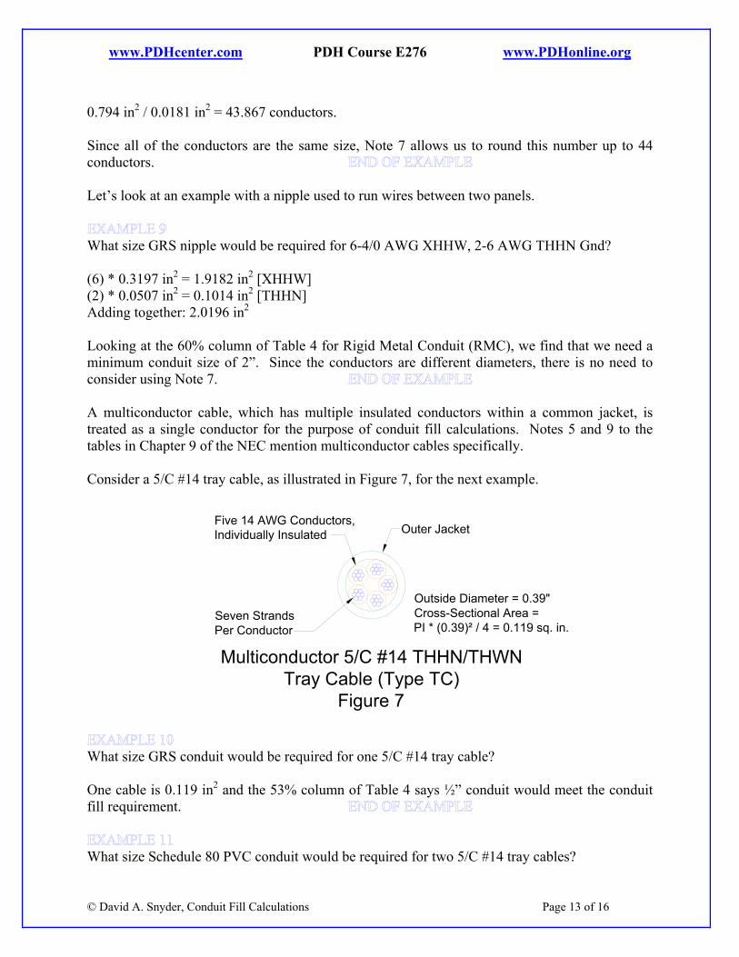
Looking at the 60% column of Table 4 for Rigid Metal Conduit (RMC), we find that we need a minimum conduit size of 2”. Since the conductors are different diameters, there is no need to consider using Note 7. A multiconductor cable, which has multiple insulated conductors within a common jacket, is treated as a single conductor for the purpose of conduit fill calculations. Notes 5 and 9 to the tables in Chapter 9 of the NEC mention multiconductor cables specifically. Consider a 5/C #14 tray cable, as illustrated in Figure 7, for the next example.
Multiconductor 5/C #14 THHN/THWNTray Cable (Type TC)
Figure 7
Outside Diameter = 0.39"Cross-Sectional Area =PI * (0.39)² / 4 = 0.119 sq. in.
Outer JacketFive 14 AWG Conductors,Individually Insulated
Seven StrandsPer Conductor
What size GRS conduit would be required for one 5/C #14 tray cable? One cable is 0.119 in2 and the 53% column of Table 4 says ½” conduit would meet the conduit fill requirement.
What size Schedule 80 PVC conduit would be required for two 5/C #14 tray cables?
© David A. Snyder, Conduit Fill Calculations Page 13 of 16
www.PDHcenter.com PDH Course E276 www.PDHonline.org
Two cables would be 2 * 0.119 in2 = 0.238 in2. It might seem that the 31% column of Table 6 tells us that 1-1/4” conduit would be required, but let’s see if we can use Note 7, since both of the cables are the same physical size. The 31% column of Table 6 at 1” says we have 0.213 in2 to work with, and if we divide that by the area of one cable we get 0.213 in2 / 0.119 in2 = 1.79 which can be rounded up to 1.8, since that is all the accuracy that we need. Therefore, 1” conduit would meet the maximum conduit fill.
How many 5/C #14 tray cables would fit in a 2” galvanized rigid steel (GRS) conduit? Assuming more than two cables will fit, a 2” GRS (RMC) conduit has a 40% area of 1.363 in2 (from Table 4), and the cross-sectional area of one cable is 0.119 in2, therefore: 1.363 / 0.119 = 11.5, so the answer is 11.
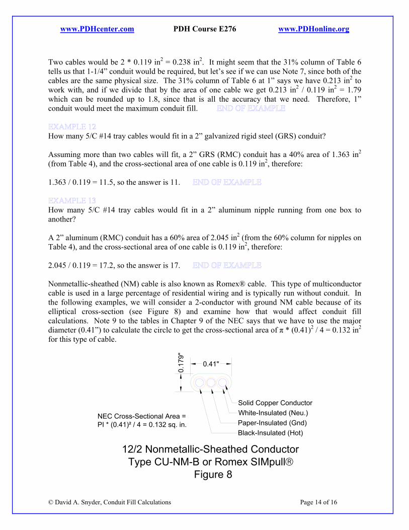
How many 5/C #14 tray cables would fit in a 2” aluminum nipple running from one box to another? A 2” aluminum (RMC) conduit has a 60% area of 2.045 in2 (from the 60% column for nipples on Table 4), and the cross-sectional area of one cable is 0.119 in2, therefore: 2.045 / 0.119 = 17.2, so the answer is 17. Nonmetallic-sheathed (NM) cable is also known as Romex® cable. This type of multiconductor cable is used in a large percentage of residential wiring and is typically run without conduit. In the following examples, we will consider a 2-conductor with ground NM cable because of its elliptical cross-section (see Figure 8) and examine how that would affect conduit fill calculations. Note 9 to the tables in Chapter 9 of the NEC says that we have to use the major diameter (0.41”) to calculate the circle to get the cross-sectional area of π * (0.41)2 / 4 = 0.132 in2 for this type of cable.
© David A. Snyder, Conduit Fill Calculations Page 14 of 16
12/2 Nonmetallic-Sheathed ConductorType CU-NM-B or Romex SIMpull®
Figure 8
0.41"
0.17
9"
White-Insulated (Neu.)Paper-Insulated (Gnd)Black-Insulated (Hot)
Solid Copper Conductor
NEC Cross-Sectional Area =PI * (0.41)² / 4 = 0.132 sq. in.
www.PDHcenter.com PDH Course E276 www.PDHonline.org
In one way, it makes sense to use the longer diameter of the ellipse to calculate the cross-sectional area, since we won’t be able to control which way the long and short diameters will be oriented as the cable twists through the conduit.
What size Schedule 40 PVC conduit would be required for one 12/2 NM cable? One NM cable has an NEC cross-sectional area of 0.132 in2. Looking at the 53% column of Table 5 indicates that a ½” conduit at 0.151 in2 would meet the NEC requirement for conduit fill. Even though ½” conduit would meet this requirement, it would actually be difficult to pull this jacketed solid-conductor cable through any ½” conduit fittings. To re-state this, ½” conduit would meet the NEC requirements, but it would make everyone’s life easier to use ¾” or larger conduit, since this is solid wire, not stranded.
What size Schedule 40 PVC conduit would be required for two 12/2 NM cables? The cross-sectional area for two cables would be 2 * 0.132 in2 = 0.264 in2. Looking at the 31% column of Table 5 might tell us that 1-1/4” conduit would be required, but let’s check to see if Note 7 will allow us to use 1” conduit. The 1” 31% column of Table 5 says we have 0.258 in2 to work with, and if we divide that by the area of one cable, we get 0.258 in2 / 0.132 in2 = 1.95. Therefore, 1” conduit would meet the conduit fill requirement.
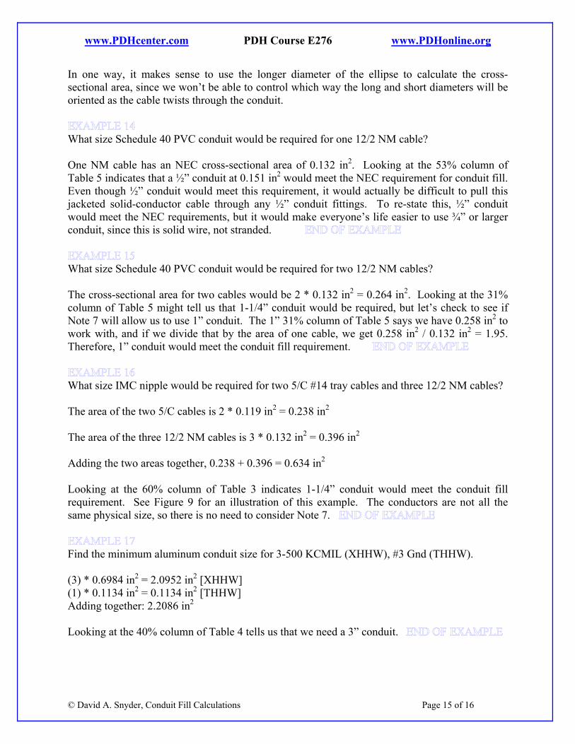
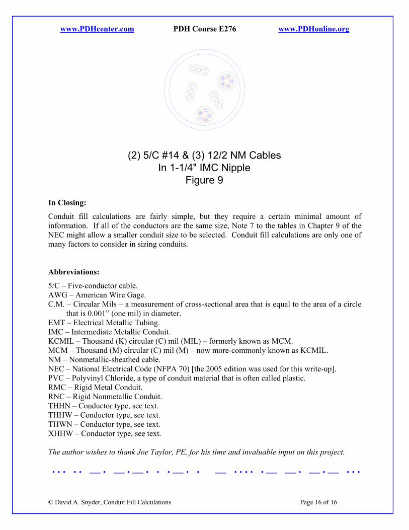
What size IMC nipple would be required for two 5/C #14 tray cables and three 12/2 NM cables? The area of the two 5/C cables is 2 * 0.119 in2 = 0.238 in2
The area of the three 12/2 NM cables is 3 * 0.132 in2 = 0.396 in2
Adding the two areas together, 0.238 + 0.396 = 0.634 in2
Looking at the 60% column of Table 3 indicates 1-1/4” conduit would meet the conduit fill requirement. See Figure 9 for an illustration of this example. The conductors are not all the same physical size, so there is no need to consider Note 7.
Find the minimum aluminum conduit size for 3-500 KCMIL (XHHW), #3 Gnd (THHW). (3) * 0.6984 in2 = 2.0952 in2 [XHHW] (1) * 0.1134 in2 = 0.1134 in2 [THHW] Adding together: 2.2086 in2
Looking at the 40% column of Table 4 tells us that we need a 3” conduit.
© David A. Snyder, Conduit Fill Calculations Page 15 of 16
www.PDHcenter.com PDH Course E276 www.PDHonline.org
(2) 5/C #14 & (3) 12/2 NM CablesIn 1-1/4" IMC Nipple
Figure 9 In Closing:
Conduit fill calculations are fairly simple, but they require a certain minimal amount of information. If all of the conductors are the same size, Note 7 to the tables in Chapter 9 of the NEC might allow a smaller conduit size to be selected. Conduit fill calculations are only one of many factors to consider in sizing conduits. Abbreviations:
5/C – Five-conductor cable. AWG – American Wire Gage. C.M. – Circular Mils – a measurement of cross-sectional area that is equal to the area of a circle
that is 0.001” (one mil) in diameter. EMT – Electrical Metallic Tubing. IMC – Intermediate Metallic Conduit. KCMIL – Thousand (K) circular (C) mil (MIL) – formerly known as MCM. MCM – Thousand (M) circular (C) mil (M) – now more-commonly known as KCMIL. NM – Nonmetallic-sheathed cable. NEC – National Electrical Code (NFPA 70) [the 2005 edition was used for this write-up]. PVC – Polyvinyl Chloride, a type of conduit material that is often called plastic. RMC – Rigid Metal Conduit. RNC – Rigid Nonmetallic Conduit. THHN – Conductor type, see text. THHW – Conductor type, see text. THWN – Conductor type, see text. XHHW – Conductor type, see text. The author wishes to thank Joe Taylor, PE, for his time and invaluable input on this project.
© David A. Snyder, Conduit Fill Calculations Page 16 of 16
· · · · · — · — · — · · · — · · — · · · · · — — · — · — · · ·