Embed Size (px)
DESCRIPTION
Electrical wiring design
Citation preview

CONDUCTOR INSULATION
The NEC® requires that all conductors be insulated,310.2 (A). There are a few
exceptions, such as the permission to use a bare neutral conductor for services, and
bare equipment grounding conductors.
The classification of insulation, either thermoplastic or thermoset, generally
determines its suitability for use under various ambient conditions. Thermoplastic
materials, typically plastic resins, soften and flow when they are heated and
subjected to pressure, but they become rigid when cooled. Thermoset materials, by
contrast, are initially set or cured when heated, but after curing they will not soften,
flow, or distort.
Some kinds of insulation are approved for wire only if it is to remain in a dry
environment, preferably within a building, but other insulating materials have been
formulated to stand up to environments that are dry and damp, dry and wet, or wet,
and still other materials can withstand extreme temperatures. For example, some
insulated wire can perform effectively only up to 60°C (140°F), while others can
perform effectively at temperatures as high as 90°C (194°F).
All modern electrical wire insulation is rated as flame-retardant, but only a few of
these insulation materials are capable of remaining effective insulators following
long-term exposure to sunlight (ultraviolet radiation), ozone, or nuclear radiation.
PURPOSE
Conductors need to be electrically isolated from other conductors and from the
environment to prevent short circuits. Insulation is applied around a conductor to
provide this isolation. Most wire and cable insulations consist of polymers
(plastics), which have a high resistance, to the flow of electric current. A jacket is
the outermost layer of a cable whose primary function is to protect the insulation
and conductor core from external physical forces and chemical deterioration.
TYPES AND APPLICATIONS
Thermoplastic Insulation: Thermo means heat and plastic means formable,
thermoplastic is soften and melt if heated above its rated temperature. It can be
heated, melted, and reshaped. Thermoplastic insulation will stiffen at temperatures
colder than 14°F (minus 10°C). Thermoplastic is lower in cost and lighter in
weight and most commonly used. Thermoplastic compounds are materials that go
soft when heated and harden when cooled.
PVC (Polyvinyl Chloride): – is the most commonly used thermoplastic insulator
for cables. It is cheap, durable and widely available. However, the chlorine in PVC
(a halogen) causes the production of thick, toxic, black smoke when burnt and can
be a health hazard in areas where low smoke and toxicity are required (e.g.
confined areas such as tunnels). Sometimes referred to simply as ―vinyl,‖ PVC
does not usually exhibit extremely high- and low-temperature properties in one
formulation. Certain formulations may have a –55°C to 105°C rating, while other
common vinyls may have a –20°C to 60°C rating. The many varieties of PVC also
differ in pliability and electrical properties. The price range can vary accordingly.
Typical dielectric constant values range from 3.5 to 6.5.
When properly formulated, thermoplastic jackets of PVC provide cables with the
ability to resist oils, acids, alkalis, sunlight, heat, weathering and abrasion. This
range of properties makes PVC a suitable outer covering for such cable types as
underground feeders (Type UF), control, aerial, street lighting and cables for direct
burial.
PE (Polyethylene) – is part of a class of polymers called polyolefins.
Polyethylene has lower dielectric losses than PVC and is sensitive to moisture
under voltage stress (i.e. for high voltages only).
Polyethylene has excellent electrical properties. It has a low dielectric constant, a
stable dielectric constant over a wide frequency range, and very high insulation
resistance. However, polyethylene is stiff and very hard, depending on molecular
weight and density. Low density PE (LDPE) is the most flexible, with high-
density, high-molecular weight formulations being least flexible. Moisture
resistance is excellent. Properly formulated PE has excellent weather resistance.
The dielectric constant is 2.3 for solid and 1.6 for cellular (foamed) insulation.

Flame retardant formulations are available, but they tend to have poorer electrical
properties.
Fluoropolymers
Fluoropolymers, with the exception of PTFE Teflon(sometimes called TFE), are
extrudable thermoplastics used in a variety of low-voltage insulating situations.
Fluoropolymers contain fluorine in their molecular composition, which contributes
to their excellent thermal, chemical, mechanical and electrical characteristics. The
most commonly used fluoropolymers are Teflon(PTFE, FEP and PFA), Tefzel
(ETFE), Halar (ECTFE) and Kynar or Solef (PVDF).Teflon has excellent electrical
properties, temperature range and chemical resistance. It is not suitable where
subjected to nuclear radiation and does nothave good high-voltage characteristics.
FEP Teflon is extrudable in a manner similar to PVC and polyethylene. This
means that long wire and cable lengths are available. PTFE Teflon is extrudable in
a hydraulic ram type process. Lengths are limited due to the amount of material in
the ram, thickness of the insulation and preform size. PTFE must be extruded over
a silver- or nickel-coated wire. The nickel- and silver-coated designs are rated
260°C and 200°C maximum, respectively. The cost of Teflon is approximately 8 to
10 times more per pound than PVC compounds.

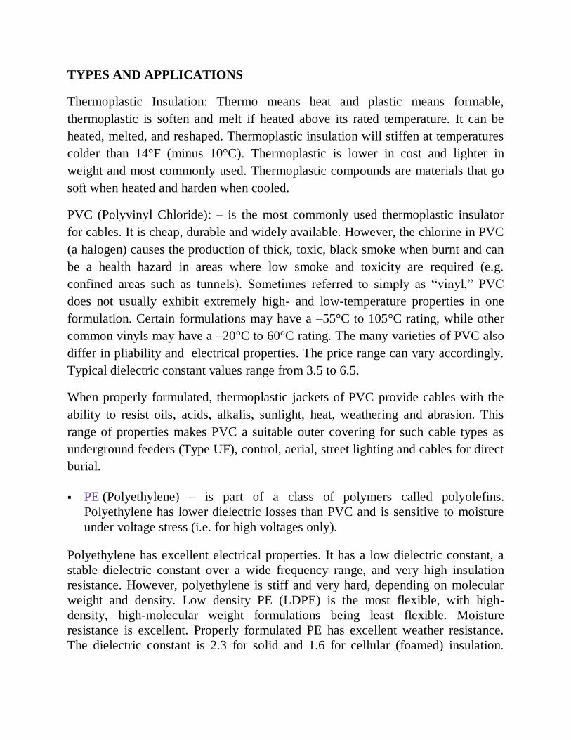
Figure 1. Typical low voltage PVC cable

Figure 1. Typical low voltage PVC cable
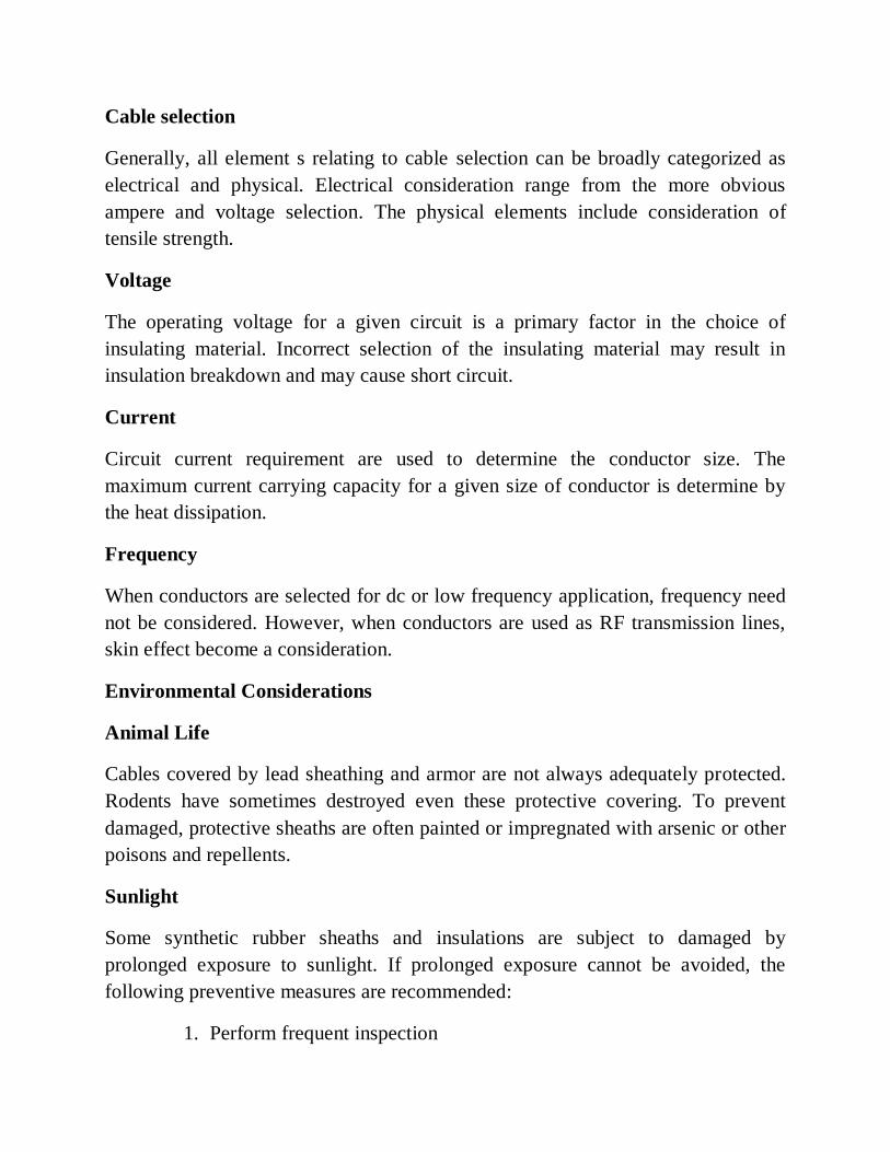
Figure 2. LV/MV cable for outdoor usage with PE sheath

Thermoset: Thermo =heat and set = fixed, thermoset materials do not melt when
heated. Onced cured cannot be recycled like thermoplastic. Once the ingredients
have been mixed, heated, and formed, it can never be reheated and reshaped. If
heated above its rated temperature, it will char and crack. Thermoset is more
flexible at lower temperatures.
XLPE (Cross-Linked Polyethylene) – has different polyethylene chains linked
together (―cross-linking‖) which helps prevent the polymer from melting or
separating at elevated temperatures. Therefore XLPE is useful for higher
temperature applications. XLPE has higher dielectric losses than PE, but has
better ageing characteristics and resistance to water treeing. Normal operating
temperatures are typically between 90C and 110C. Temperature limit is 250C.
EPR (Ethylene Propylene Rubber) – is a copolymer of ethylene and
propylene, and commonly called an ―elastomer‖. EPR is more flexible than
PE and XLPE, but has higher dielectric losses than both. Normal operating
temperatures are typically between 90C and 110C. Temperature limit is
250C.
Figure 3. 3-phase EPR insulated cable for MV

Figure 4. MV cable with XLPE insulation, 33 kV

Comparison of Materials
A comparison of common insulating materials is as follows:
Material Advantages Disadvantages
PVC
Cheap
Durable
Widely available
Highest dielectric losses
Melts at high temperatures
Contains halogens
Not suitable for MV / HV cables
PE
Lowest dielectric
losses
High initial dielectric
strength
Highly sensitive to water treeing
Material breaks down at high
temperatures
XLPE
Low dielectric losses
Improved material
properties at high
temperatures
Does not melt but
thermal expansion
occurs
Medium sensitivity to water treeing
(although some XLPE polymers are
water-tree resistant)
EPR
Increased flexibility
Reduced thermal
expansion (relative to
XLPE)
Low sensitivity to
water treeing
Medium-High dielectric losses
Requires inorganic filler / additive
Paper /
Oil
Low-Medium dielectric
losses
Not harmed by DC
testing
Known history of
reliability
High weight
High cost
Requires hydraulic pressure / pumps for
insulating fluid
Difficult to repair
Degrades with moisture

A letter code has been established to simplify the selection of the optimum
insulated wire for specific tasks while considering operating temperatures and
application environments. A knowledge of this code will permit the user suffucient
background information to make the best selection. Examples of these code
designations are RHH, THHN, TW, and XHHW.
Copper and aluminum wire are identifiable on sight by their color—reddish brown
for copper and silver for aluminum. However, it is difficult to identify copper-clad
aluminum wire on sight without making a clean cut through the wire to examine
the core.
On the other hand, even experts have trouble identifying wire insulation. For this
reason, manufacturers print an identification code directly on the wire insulation,
giving:
■The trade name of the insulation
■Maximum operating temperature (H for 75°C, HH for 90°C, none for 60°C)
■Environments for safe application (dry, damp, wet, or combinations of these)
■Year of manufacture
■Maximum voltage rating


Cable selection
Generally, all element s relating to cable selection can be broadly categorized as
electrical and physical. Electrical consideration range from the more obvious
ampere and voltage selection. The physical elements include consideration of
tensile strength.
Voltage
The operating voltage for a given circuit is a primary factor in the choice of
insulating material. Incorrect selection of the insulating material may result in
insulation breakdown and may cause short circuit.
Current
Circuit current requirement are used to determine the conductor size. The
maximum current carrying capacity for a given size of conductor is determine by
the heat dissipation.
Frequency
When conductors are selected for dc or low frequency application, frequency need
not be considered. However, when conductors are used as RF transmission lines,
skin effect become a consideration.
Environmental Considerations
Animal Life
Cables covered by lead sheathing and armor are not always adequately protected.
Rodents have sometimes destroyed even these protective covering. To prevent
damaged, protective sheaths are often painted or impregnated with arsenic or other
poisons and repellents.
Sunlight
Some synthetic rubber sheaths and insulations are subject to damaged by
prolonged exposure to sunlight. If prolonged exposure cannot be avoided, the
following preventive measures are recommended:
1. Perform frequent inspection

2. Treat cable surface with silicone compound
3. Paint cables with a rubber base preservative paint.
Ozone
Ozone(O3) is a form of oxygen which, unlike oxygen in its normal state (o2), is
harmful to rubber and rubber compounds. The preventive measure should be taken
such case.
Extreme climatic conditions
Extreme cold, salt air, hot humid air, and other climatic conditions must be
considered when the type of cable to be used is determined.
Insulation Resistance Testing
Insulation starts to age as soon as it's made. As it ages, its insulating performance
deteriorates. Any harsh installation environments, especially those with
temperature extremes and/or chemical contamination, accelerates this process. This
deterioration can result in dangerous conditions in power reliability and personnel
safety. As such, it's important to identify this deterioration quickly so that
corrective steps can be taken. The most important reason for testing insulation is to
insure public and personal safety. By performing a high dc voltage test between
de-energized current-carrying (hot), grounded, and grounding conductors, you can
eliminate the possibility of having a life-threatening short circuit or short to
ground. One of the simplest tests and its required test instrument are not
universally understood.
Insulation testing components
The insulation resistance (IR) test (also commonly known as a Megger) is a spot
insulation test which uses an applied DC voltage (typically either 250Vdc, 500Vdc
or 1,000Vdc for low voltage equipment <600V and 2,500Vdc and 5,000Vdc for
high voltage equipment) to measure insulation resistance in either kΩ, MΩ or GΩ.
The measured resistance is intended to indicate the condition of the insulation or
dieletric between two conductive parts, where the higher the resistance, the better
the condition of the insulation. Ideally, the insulation resistance would be infinite,

but as no insulators are perfect, leakage currents through the dielectric will ensure
that a finite (though high) resistance value is measured.
The megohmmeter( megger)
Megohmmeter (sometimes referred to as a megger) is a special type
of ohmmeter used to measure the electrical resistance of insulators. Insulating
components, for example cable jackets, must be tested for their insulation strength
at the time of commissioning and as part of maintenance of high voltage electrical
equipment and installations. For this purpose megohmmeters, which can provide
high DC voltages (typically in ranges from 500V to 2kV) at specified current
capacity, are used. Acceptable insulator resistance values are typically 1 to 10
megohms, depending on the standards referenced.
A basic megohmmeter hook-up schematic is shown in Fig. 1 (above). The
megohmmeter is similar to a multimeter, when the latter is in its ohmmeter
function. There are differences, however.
First, the megohmmeter's output is much higher than that of a multimeter. Voltages
of 100, 250, 500, 1,000, 2500, 5,000, and even 10,000V are. The most common
voltages are 500V and 1,000V. Higher voltages are used to stress an insulation to a
greater degree and thus obtain more accurate results.
econd, the range of a megohmmeter is in megohms, as its name implies, instead of
ohms as in a multimeter.
Third, a megohmmeter has a relatively high internal resistance, making the
instrument less hazardous to use in spite of the higher voltages.

Ground Resistance Measuring
Why grounding?
Lack of good grounding is dangerous and increases the risk of equipment failure.
Without an effective grounding system, we could be exposed to the risk of electric
shock, not to mention instrumentation errors, harmonic distortion issues, power
factor problems and a host of possible intermittent dilemmas. If fault currents have
no path to the ground through a properly designed and maintained grounding
system, they will find unintended paths that could include people.
However, good grounding isn’t only for safety; it is also used to prevent damage to
industrial plants and equipment. A good grounding system will improve the
reliability of equipment and reduce the likelihood of damage due to lightning or
fault currents. Billions are lost each year in the workplace due to electrical fires.
This does not account for related litigation costs and loss of personal and corporate
productivity.
Why test grounding resistance or why determine the soil resistivity?
Soil Resistivity is most necessary when determining the design of the grounding
system for new installations (green field applications) to meet your ground
resistance requirements. Ideally, you would find a location with the lowest possible
resistance. But as we discussed before, poor soil conditions can be overcome with
more elaborate grounding systems. The soil composition, moisture content, and
temperature all impact the soil resistivity. Soil is rarely homogenous and the
resistivity of the soil will vary geographically and at different soil depths. Moisture
content changes seasonally, varies according to the nature of the sub layers of
earth, and the depth of the permanent water table. Since soil and water are
generally more stable at deeper strata, it is recommended that the ground rods be
placed as deep as possible into the earth, at the water table if possible. Also,
ground rods should be installed where there is a stable temperature, i.e. below the
frost line. For a grounding system to be effective, it should be designed to
withstand the worst possible conditions.

Over time, corrosive soils with high moisture content, high salt content, and high
temperatures can degrade ground rods and their connections. So although the
ground system when initially installed, had low earth ground resistance values, the
resistance of the grounding system can increase if the ground rods are eaten away.
That is why it is highly recommended that all grounds and ground connections are
checked at least annually as a part of your normal Predictive Maintenance plan.
During these periodic checks, if an increase in resistance of more than 20 % is
measured, the technician should investigate the source of the problem, and make
the correction to lower the resistance, by replacing or adding ground rods to the
ground system.
Earth resistance is measured in two ways for two important fields of use:
1. Determining effectiveness of ―ground‖ grids and connections that are used with
electrical systems to protect personnel and equipment.
2. Prospecting for good (low resistance) ―ground‖ locations, or obtaining measured
resistance values that can give specific information about what lies some distance
below the earth’s surface (such as depth to bed rock).
What is a good ground resistance value?
There is a good deal of confusion as to what constitutes a good ground and what
the ground resistance value needs to be. Ideally a ground should be of zero ohms
resistance. There is not one standard ground resistance threshold that is recognized
by all agencies.
However, the NFPA and IEEE have recommended a ground resistance value of 5.0
ohms or less.
The NEC has stated to ―Make sure that system impedance to ground is less than 25
ohms specified in NEC 250.56. In facilities with sensitive equipment it should be
5.0 ohms or less.‖
The Telecommunications industry has often used 5.0 ohms or less as their value
for grounding and bonding.

The goal in ground resistance is to achieve the lowest ground resistance value
possible that makes sense economically and physically.