Embed Size (px)
Citation preview
New Product
1
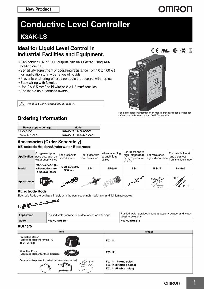
Conductive Level ControllerK8AK-LS
Ideal for Liquid Level Control in Industrial Facilities and Equipment.• Self-holding ON or OFF outputs can be selected using self-
holding circuit.• Sensitivity adjustment of operating resistance from 10 to 100 kΩ
for application to a wide range of liquids.• Prevents chattering of relay contacts that occurs with ripples.• Easy wiring with ferrules.• Use 2 × 2.5 mm2 solid wire or 2 × 1.5 mm2 ferrules.• Applicable as a floatless switch.
Ordering Information
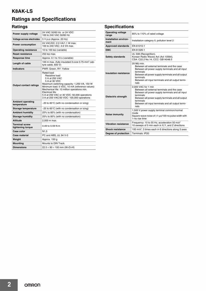
Accessories (Order Separately)Electrode Holders/Underwater Electrodes
Electrode RodsElectrode Rods are available in sets with the connection nuts, lock nuts, and tightening screws.
Others
Refer to Safety Precautions on page 7.
For the most recent information on models that have been certified for safety standards, refer to your OMRON website.
Power supply voltage Model24 VAC/DC K8AK-LS1 24 VAC/DC100 to 240 VAC K8AK-LS1 100−240 VAC
ApplicationFor general-pur-pose use, such as water supply lines
For areas with limited space
For liquids with low resistance
When mounting strength is re-quired
For resistance to high-temperature or high-pressure liquids
For resistance against corrosion
For installation at long distances from the liquid level
ModelPS-3S/-4S/-5S (2-wire models are also available)
PS-31 SUS304, 300 mm
BF-1 BF-3/-5 BS-1 BS-1T PH-1/-2
AppearanceSUS
Hastelloytitanium PH-1
PH-2
Application Purified water service, industrial water, and sewage Purified water service, industrial water, sewage, and weak alkaline solutions
Model F03-60 SUS304 F03-60 SUS316
Item Model
F03-11
F03-12
F03-14 1P (one pole)F03-14 3P (three poles)F03-14 5P (five poles)
Protective Cover (Electrode Holders for the PS or BF Series)
Mounting Piece (Electrode Holder for the PS Series)
Separator (to prevent contact between electrodes)
K8AK-LS
2
Ratings and SpecificationsRatings Specifications
Power supply voltage 24 VAC 50/60 Hz or 24 VDC100 to 240 VAC 50/60 Hz
Voltage across electrodes 5 V p-p (Approx. 20 Hz)
Power consumption 24 VAC/DC: 2.0 VA/1.1 W max.100 to 240 VAC: 4.6 VA max.
Operating resistance 10 to 100 kΩ (variable)
Reset resistance 250 kΩ max.
Response time Approx. 0.1 to 10 s (variable)
Length of cable 100 m max. (fully insulated 3-core 0.75-mm2 cab-tyre cable, 600 V)
Indicators PWR: Green, RY: Yellow
Output contact ratings
Rated loadResistive load5 A at 250 VAC5 A at 30 VDC
Maximum switching capacity: 1,250 VA, 150 WMinimum load: 5 VDC, 10 mA (reference values)Mechanical life: 10 million operations min.Electrical life: 5 A at 250 VAC or 30 VDC: 50,000 operations3 A at 250 VAC/30 VDC: 100,000 operations
Ambient operating temperature −20 to 60°C (with no condensation or icing)
Storage temperature −25 to 65°C (with no condensation or icing)
Ambient humidity 25% to 85% (with no condensation)
Storage humidity 25% to 85% (with no condensation)
Altitude 2,000 m max.
Terminal screw tightening torque 0.49 to 0.59 N·m
Case color N1.5
Case material PC and ABS, UL 94 V-0
Weight Approx. 150 g
Mounting Mounts to DIN Track.
Dimensions 22.5 × 90 × 100 mm (W×D×H)
Operating voltage range 85% to 110% of rated voltage
Installation environ-ment Installation category II, pollution level 2
Approved standards EN 61010-1
EMC EN 61326-1
Safety standardsUL 508 (Recognition), Korean Radio Waves Act (Act 10564), CSA: C22.2 No.14, CCC: GB14048.5
Insulation resistance
20 MΩ min.Between all external terminals and the caseBetween all power supply terminals and all input terminalsBetween all power supply terminals and all output terminalsBetween all input terminals and all output termi-nals
Dielectric strength
2,000 VAC for 1 minBetween all external terminals and the caseBetween all power supply terminals and all input terminalsBetween all power supply terminals and all output terminalsBetween all input terminals and all output termi-nals
Noise immunity
1,500 V power supply terminal common/normal modeSquare-wave noise of ±1-µs/100-ns pulse width with 1-ns rise time
Vibration resistance Frequency: 10 to 55 Hz, acceleration 50 m/s2
10 sweeps of 5 min each in X,Y, and Z directions
Shock resistance 100 m/s2, 3 times each in 6 directions along 3 axes
Degree of protection Terminals: IP20
K8AK-LS
3
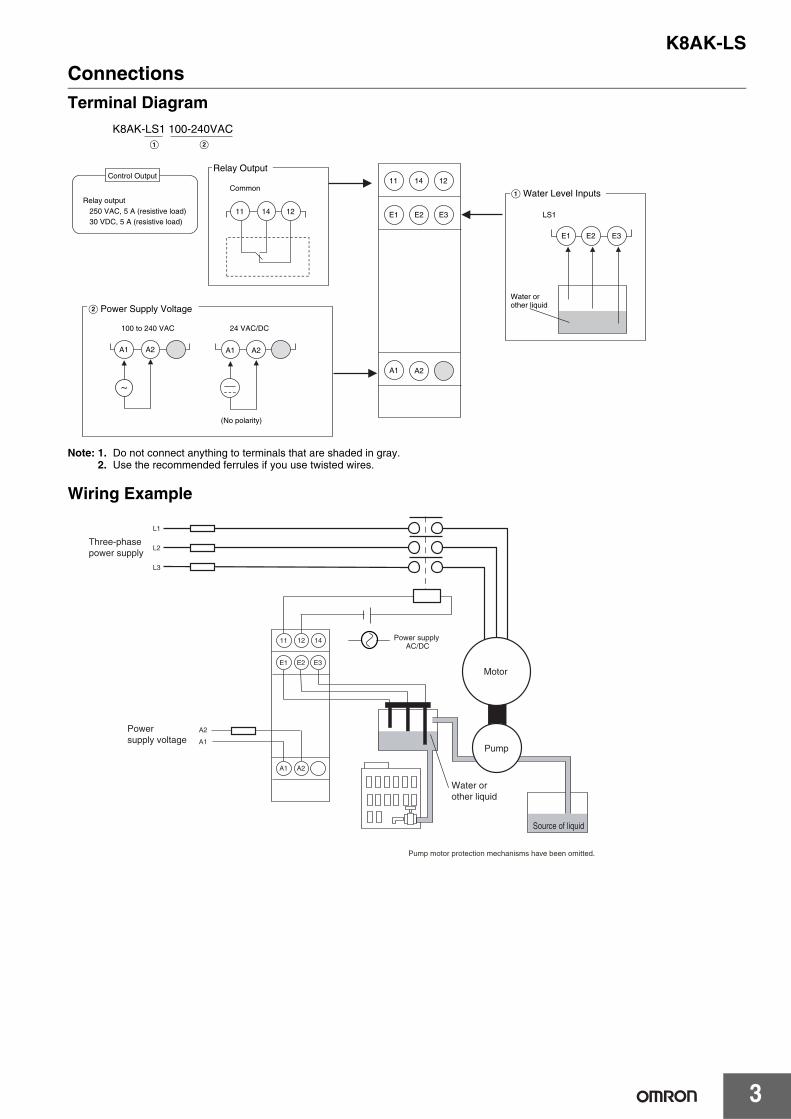
ConnectionsTerminal Diagram
Note: 1. Do not connect anything to terminals that are shaded in gray.2. Use the recommended ferrules if you use twisted wires.
Wiring Example
K8AK-LS1 100-240VACA B
E1 E2 E3
A1 A2
11 14
Relay output250 VAC, 5 A (resistive load)30 VDC, 5 A (resistive load)
A Water Level Inputs
LS1
B Power Supply Voltage
100 to 240 VAC 24 VAC/DC
(No polarity)
12
Relay Output
Common
Water or other liquid
Control Output
A2A1 A2A1
E1 E2 E3
11 14 12
Power supply voltage
Water or other liquid
E1 E2 E3
A1 A2
A1
A2
12 1411
L1
L2
L3
Pump motor protection mechanisms have been omitted.
Source of liquid
Motor
Pump
Three-phase power supply
Power supply AC/DC
K8AK-LS
4
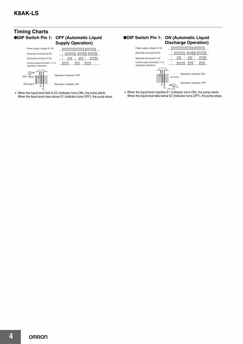
Timing ChartsDIP Switch Pin 1: OFF (Automatic Liquid
Supply Operation)
• When the liquid level falls to E2 (indicator turns ON), the pump starts. When the liquid level rises above E1 (indicator turns OFF), the pump stops.
DIP Switch Pin 1: ON (Automatic Liquid Discharge Operation)
• When the liquid level reaches E1 (indicator turns ON), the pump starts. When the liquid level falls below E2 (indicator turns OFF), the pump stops.
Power supply voltage A1-A2
Electrode terminals E2-E3
Electrode terminals E1-E3
Control output terminals 11-14 (operation indication)
P
OFF (stop)
ON (start)
Operation indicator OFF
Operation indicator ON
E1
E2
E3
Power supply voltage A1-A2
Electrode terminals E2-E3
Electrode terminals E1-E3
Control output terminals 11-14 (operation indication)
P
OFF (stop)
ON (start)
Operation indicator ON
Operation indicator OFF
E1
E2
E3
K8AK-LS
5
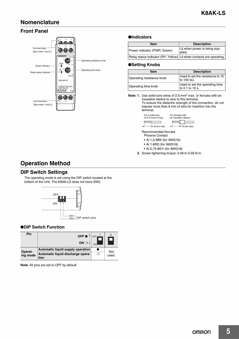
NomenclatureFront Panel
Indicators
Setting Knobs
Note: 1. Use solid-core wires of 2.5-mm2 max. or ferrules with an insulation sleeve to wire to this terminal.To ensure the dielectric strength of the connection, do not expose more than 8 mm of wire for insertion into the terminal.
Recommended ferrulesPhoenix Contact• Al 1,5-8BK (for AWG16)• Al 1-8RD (for AWG18)• Al 0,75-8GY (for AWG18)
2. Screw tightening torque: 0.49 to 0.59 N·m
Operation MethodDIP Switch Settings
The operating mode is set using the DIP switch located at the bottom of the Unit. The K8AK-LS does not have SW2.
DIP Switch Function
Note: All pins are set to OFF by default.
Operating time knob
Power indicator
Relay status indicator
Operating resistance knob
Terminal block
(See notes 1 and 2.)
Terminal block
(See notes 1 and 2.)
Item Description
Power indicator (PWR: Green) Lit when power is being sup-plied.
Relay status indicator (RY: Yellow) Lit when contacts are operating.
Item Description
Operating resistance knob Used to set the resistance to 10 to 100 kΩ.
Operating time knob Used to set the operating time to 0.1 to 10 s.
8 mm max. 8 mm max.
For a solid wire of 2.5-mm2 of max.
For ferrules with an insulation sleeve.
PinOFF ↑
ON ↓
Operat-ing mode
Automatic liquid supply operation Not
used.Automatic liquid discharge opera-tion
SW2 DIP switch pins
ON
OFF
SW1
1OFF
ON
2
K8AK-LS
6
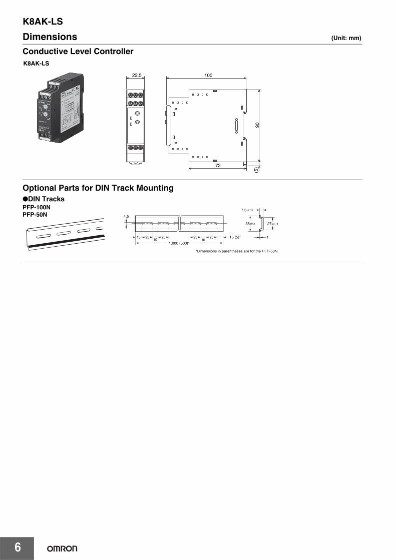
Dimensions (Unit: mm)
Conductive Level Controller
Optional Parts for DIN Track Mounting
22.5
90
100
72
(5)
K8AK-LS
DIN TracksPFP-100NPFP-50N
*Dimensions in parentheses are for the PFP-50N.
4.5
15 25 2510 10
1,000 (500)*
25 25 15 (5)*
35±0.3
7.3±0.15
27±0.15
1
K8AK-LS
7
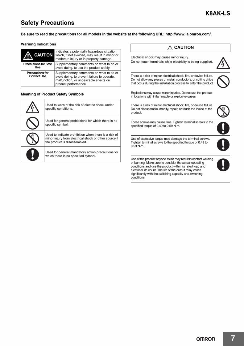
Safety Precautions
Be sure to read the precautions for all models in the website at the following URL: http://www.ia.omron.com/.
Warning Indications
Meaning of Product Safety Symbols
Electrical shock may cause minor injury.Do not touch terminals while electricity is being supplied.
There is a risk of minor electrical shock, fire, or device failure. Do not allow any pieces of metal, conductors, or cutting chips that occur during the installation process to enter the product.
Explosions may cause minor injuries. Do not use the product in locations with inflammable or explosive gases.
There is a risk of minor electrical shock, fire, or device failure. Do not disassemble, modify, repair, or touch the inside of the product.
Loose screws may cause fires. Tighten terminal screws to the specified torque of 0.49 to 0.59 N·m.
Use of excessive torque may damage the terminal screws. Tighten terminal screws to the specified torque of 0.49 to 0.59 N·m.
Use of the product beyond its life may result in contact welding or burning. Make sure to consider the actual operating conditions and use the product within its rated load and electrical life count. The life of the output relay varies significantly with the switching capacity and switching conditions.
CAUTIONIndicates a potentially hazardous situation which, if not avoided, may result in minor or moderate injury or in property damage.
Precautions for Safe Use
Supplementary comments on what to do or avoid doing, to use the product safely.
Precautions for Correct Use
Supplementary comments on what to do or avoid doing, to prevent failure to operate, malfunction, or undesirable effects on product performance.
Used to warn of the risk of electric shock under specific conditions.
Used for general prohibitions for which there is no specific symbol.
Used to indicate prohibition when there is a risk of minor injury from electrical shock or other source if the product is disassembled.
Used for general mandatory action precautions for which there is no specified symbol.
CAUTION
K8AK-LS
8
1. Do not use or store the product in the following locations.• Locations subject to water or oil
• Outdoor locations or under direct sunlight
• Locations subject to dust or corrosive gases (particularly sulfurizing gases, ammonia, etc.)
• Locations subject to rapid temperature changes
• Locations prone to icing and dew condensation
• Locations subject to excessive vibration or shock
• Locations subject to wind and rain
• Locations subject to static electricity and noise
• Habitats of insects or small animals
2. Use and store the product in a location where the ambient temperature and humidity are within the specified ranges. If applicable, provide forced cooling.
3. Mount the product in the correct direction.4. Check terminal polarity when wiring and wire all connections
correctly. The power supply terminals do not have polarity.5. Do not wire the input and output terminals incorrectly.6. Make sure the power supply voltage and loads are within the
specifications and ratings for the product.7. Make sure the crimp terminals for wiring are of the specified size.8. Do not connect anything to terminals that are not being used.9. Use a power supply that will reach the rated voltage within 1
second after the power is turned ON.10.Keep wiring separate from high voltages and power lines that
draw large currents. Do not place product wiring in parallel with or in the same path as high-voltage or high-current lines.
11.Do not install the product near equipment that generates high frequencies or surges.
12.The product may cause incoming radio wave interference. Do not use the product near radio wave receivers.
13.Install an external switch or circuit breaker and label it clearly so that the operator can quickly turn OFF the power supply.
14.Make sure the indicators operate correctly. Depending on the application environment, the indicators may deteriorate prematurely and become difficult to see.
15.The terminal blocks may heat up to 65°C. Use care when handling them.
16.Do not use the product if it is accidentally dropped. The internal components may be damaged.
17.Be sure you understand the contents of this catalog and handle the product according to the instructions provided.
18.Do not install the product in any way that would place a load on it.19.When discarding the product, properly dispose of it as industrial
waste.20.When using the product, remember that the power supply
terminals carry a high voltage.21.The product must be handled only by trained electrician.22.Prior to operation, check the wiring before you supply power to
the product.23.Do not install the product immediately next to heat sources.24.Perform periodic maintenance.
Observe the following operating methods to prevent failure and malfunction.1. Use the power supply voltage, input power, and other power
supplies and converters with suitable capacities and rated outputs.
2. Use a precision screwdriver or similar tool to adjust the setting knobs.
3. When cleaning the product, do not use thinners or solvents. Use commercial alcohol.
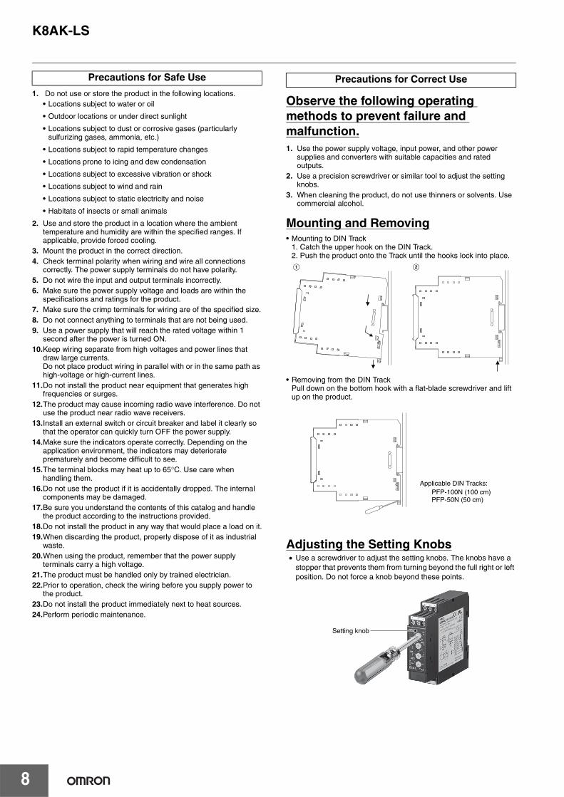
Mounting and Removing• Mounting to DIN Track
1. Catch the upper hook on the DIN Track.2. Push the product onto the Track until the hooks lock into place.
• Removing from the DIN TrackPull down on the bottom hook with a flat-blade screwdriver and lift up on the product.
Adjusting the Setting Knobs• Use a screwdriver to adjust the setting knobs. The knobs have a
stopper that prevents them from turning beyond the full right or left position. Do not force a knob beyond these points.
Precautions for Safe Use Precautions for Correct Use
A B
PFP-100N (100 cm)PFP-50N (50 cm)
Applicable DIN Tracks:
Setting knob

MEMO
9

MEMO
10
Terms and Conditions AgreementRead and understand this catalog.
Please read and understand this catalog before purchasing the products. Please consult your OMRON representative if you have any questions or comments.
Warranties.(a) Exclusive Warranty. Omron’s exclusive warranty is that the Products will be free from defects in materials and workmanship
for a period of twelve months from the date of sale by Omron (or such other period expressed in writing by Omron). Omron disclaims all other warranties, express or implied.
(b) Limitations. OMRON MAKES NO WARRANTY OR REPRESENTATION, EXPRESS OR IMPLIED, ABOUT NON-INFRINGEMENT, MERCHANTABILITY OR FITNESS FOR A PARTICULAR PURPOSE OF THE PRODUCTS. BUYER ACKNOWLEDGES THAT IT ALONE HAS DETERMINED THAT THE PRODUCTS WILL SUITABLY MEET THE REQUIREMENTS OF THEIR INTENDED USE.
Omron further disclaims all warranties and responsibility of any type for claims or expenses based on infringement by the Products or otherwise of any intellectual property right. (c) Buyer Remedy. Omron’s sole obligation hereunder shall be, at Omron’s election, to (i) replace (in the form originally shipped with Buyer responsible for labor charges for removal or replacement thereof) the non-complying Product, (ii) repair the non-complying Product, or (iii) repay or credit Buyer an amount equal to the purchase price of the non-complying Product; provided that in no event shall Omron be responsible for warranty, repair, indemnity or any other claims or expenses regarding the Products unless Omron’s analysis confirms that the Products were properly handled, stored, installed and maintained and not subject to contamination, abuse, misuse or inappropriate modification. Return of any Products by Buyer must be approved in writing by Omron before shipment. Omron Companies shall not be liable for the suitability or unsuitability or the results from the use of Products in combination with any electrical or electronic components, circuits, system assemblies or any other materials or substances or environments. Any advice, recommendations or information given orally or in writing, are not to be construed as an amendment or addition to the above warranty.
See http://www.omron.com/global/ or contact your Omron representative for published information.
Limitation on Liability; Etc.OMRON COMPANIES SHALL NOT BE LIABLE FOR SPECIAL, INDIRECT, INCIDENTAL, OR CONSEQUENTIAL DAMAGES, LOSS OF PROFITS OR PRODUCTION OR COMMERCIAL LOSS IN ANY WAY CONNECTED WITH THE PRODUCTS, WHETHER SUCH CLAIM IS BASED IN CONTRACT, WARRANTY, NEGLIGENCE OR STRICT LIABILITY.
Further, in no event shall liability of Omron Companies exceed the individual price of the Product on which liability is asserted.
Suitability of Use.Omron Companies shall not be responsible for conformity with any standards, codes or regulations which apply to the combination of the Product in the Buyer’s application or use of the Product. At Buyer’s request, Omron will provide applicable third party certification documents identifying ratings and limitations of use which apply to the Product. This information by itself is not sufficient for a complete determination of the suitability of the Product in combination with the end product, machine, system, or other application or use. Buyer shall be solely responsible for determining appropriateness of the particular Product with respect to Buyer’s application, product or system. Buyer shall take application responsibility in all cases.
NEVER USE THE PRODUCT FOR AN APPLICATION INVOLVING SERIOUS RISK TO LIFE OR PROPERTY OR IN LARGE QUANTITIES WITHOUT ENSURING THAT THE SYSTEM AS A WHOLE HAS BEEN DESIGNED TO ADDRESS THE RISKS, AND THAT THE OMRON PRODUCT(S) IS PROPERLY RATED AND INSTALLED FOR THE INTENDED USE WITHIN THE OVERALL EQUIPMENT OR SYSTEM.
Programmable Products.Omron Companies shall not be responsible for the user’s programming of a programmable Product, or any consequence thereof.
Performance Data.Data presented in Omron Company websites, catalogs and other materials is provided as a guide for the user in determining suitability and does not constitute a warranty. It may represent the result of Omron’s test conditions, and the user must correlate it to actual application requirements. Actual performance is subject to the Omron’s Warranty and Limitations of Liability.
Change in Specifications.Product specifications and accessories may be changed at any time based on improvements and other reasons. It is our practice to change part numbers when published ratings or features are changed, or when significant construction changes are made. However, some specifications of the Product may be changed without any notice. When in doubt, special part numbers may be assigned to fix or establish key specifications for your application. Please consult with your Omron’s representative at any time to confirm actual specifications of purchased Product.
Errors and Omissions.Information presented by Omron Companies has been checked and is believed to be accurate; however, no responsibility is assumed for clerical, typographical or proofreading errors or omissions.

0513
Authorized Distributor:
In the interest of product improvement, specifications are subject to change without notice.
Cat. No. N188-E1-01 0114 (0114)
© OMRON Corporation 2014 All Rights Reserved.
OMRON Corporation Industrial Automation Company
OMRON ELECTRONICS LLCOne Commerce Drive Schaumburg,IL 60173-5302 U.S.A.Tel: (1) 847-843-7900/Fax: (1) 847-843-7787
Regional HeadquartersOMRON EUROPE B.V.Wegalaan 67-69-2132 JD HoofddorpThe NetherlandsTel: (31)2356-81-300/Fax: (31)2356-81-388
Contact: www.ia.omron.comTokyo, JAPAN
OMRON ASIA PACIFIC PTE. LTD.No. 438A Alexandra Road # 05-05/08 (Lobby 2), Alexandra Technopark, Singapore 119967Tel: (65) 6835-3011/Fax: (65) 6835-2711
OMRON (CHINA) CO., LTD.Room 2211, Bank of China Tower, 200 Yin Cheng Zhong Road, PuDong New Area, Shanghai, 200120, ChinaTel: (86) 21-5037-2222/Fax: (86) 21-5037-2200