Embed Size (px)
Citation preview

AUGUST 1954 49
CONDITIONS FOR SQUARE HYSTERESIS' LOOPS IN FERRITESby H. P. J.WIJN, E. W. GORTER, C. J. ESVELDT and P. GELDERMANS.
538.23: 621.318.134
Since ferrites were introtluced commercially by Philips nearly ten years ago, the applicationsof these soft magnetic materials have enormously increased. The further development of thesematerials has been influenced by the fact that it has been found possible to manufacture themwith properties . specially adapted to particular purposes. The present article deals with thefundamental conditions for obtaining ferrites with rectangular hysteresis loops.
Introduction
Magnetic cores with approximately rectangularhysteresis loops have a wide range of application.They are used for example in the so-called "magnet-ic memory" I) of computing machines and automaticpilots, and for magnetic switching elements.
For a memory element, the requirements are thatwhen a square pulse of a certain height is passedthrough the magnetizing coil, the core shall revert toits original condition after passage of the pulse butwhen a pulse of double this height is passed throughthe coil, the magnetization of the core shall bereversed after passage of the pulse. When the mater-ial is used for switching elements, the magnetizationmust not he affected by a positive pulse, hut musthe reversed hy a negative pulse of the same height.
The pulses employed in these techniques areusually of very short duration, so that, during thepulse, the variation in the current, di/dt, assumesvery high values, as a result of which rapid varia-tions dB/dt occur in the induction, and eddy currentsare produced.It is important that the magnitude of these eddy
currents should be minimized. In ferromagneticmetals (nickel-iron. alloys such as "Hypernik" and"Deltamax" 2)) this is to a limited extent achievedby building up the core from very thin insulatedlaminations of the material; in practice, however,it is difficult to construct such laminated cores togive nearly rectangular hysteresis loops.Magnetically soft materials such as ferrites 3),
1) J. A. Rajchman, ReA rev., 13, 183-201, 1953. A. Wang,J. appl. Phys. 21, 49-54, 1950. Some specific instances arereviewed in F. van TongerIoo, T. Nederlands Radiogenoot-schap 18, 265-285, 1953, No. 11.
2) See for example R. M. Bozorth, Ferromagnetism, VanNostrand, New York, 1952.
3) J. L. Snoek, Philips tech. Rev.8, 353,1946; J. J. Went andE. W. Gorter, The magnetic and electrical properties ofFerroxcube materials, Philips tech. Rev. 13, 181-193,1951/1952, referred to hereafter as I. As in I, the presentarticle uses the rationalized Giorgi (M.K.S.) system, inwhieh B is measured in Wb/m2 and H in A/m (!loH inWb/m2). B = 10--4 Wb/m2 corresponds to B = 1 gauss,and !loH = 10--4Wb/m2 (H = 79.5 A/m) to H = 1 oersted.!lo= 4n X 10-7 volt seconds/ampere metres. The formulaB = !loH + J takes the place of B = H + 4n1 in theelectromagnetic c.g.s. system. If J = 1Wb/m2, 4n1 =10,000 gauss and I RI 800 gauss.
which are at the same time poor conductors, offerconsiderable advantages over the use of laminatedferromagnetic metals in pulse applications (giventhat these materials can be made with rectangularhysteresis loops 4)).
Definitions of certain quantities
One or two concepts will now be introducedwhich are essential to a consideration of the pro-blem 5).The loop depicted infig. 1 (fullline) is the hysteresisloop of a ferrite. It represents the magnetization Jplotted against the magnetic field H for values
J
t
Hel-H
80671,
. Fig. 1. Hysteresis loop of a ferrite.
of H which decrease from large .positive to largenegative values, and then revert to the positivevalue. The value of the field at which the magnet-ization is zero is known as the coercive force Hcof the material 6). On decreasing the field from alarge value, the point at whi~h the magnetization
4) E. Albers-Schoenberg and D. R. Brown, Electronics 26,April 1953, p. 146. .
5) For a more detailed discussion of these concepts and theirphysical basis see J. J. Went, Philips tech. Rev. 10, 246-254.,194.8/1949.
6) In magnetic materials a distinction is made between acoercive force for the induction, BHe, i.e, the field strengthat which the induction B is zero, and a coercive force forthe magnetization, JIle, the field strength at which the mag-netization J is zero. In general, BHe and .tIle differ becauseB = !loH + J, and Band J do not become zero at thesame time. In the materials discussed here the values of Hare so small that the difference may be disregarded-and the
. single symbol (He) employed.

50 PHILIPS TECHNICAL REVIEW VOL. 16, No. Z
begins to diverge from its previous values is de-noted. Hcl; the corresponding magnetization isdenoted Je. For fields H> Hel the variations inthe magnetization are reversible. Smaller hysteresisloops are also obtainable, as shown for example bythe dotted line in fig. 1, with extreme field valuesof +Hi:n and ---:-Hm(Hm < Hel). As a measure ofthe effectiveness of ferrites for the cores of memorydevices the concept of "squareness" is introduced,defined as:
Rs= B-tHmBHm
or, what' is practically equivalent,
The demoninator and numerator of the latterrepresent respectively the magnetization for a field+Hm and that for a field -!Hm. It will be clearthat Rs is also a function of the maximum field Hmdetermining the size of the loop. When Rs is measu-red as a function of Hm it is found that a maximumoccurs for a certain value of Hm; let this maximumbe denoted by (Rs)max. With ferrites for which(Rs)max> 0.7, this value of Hm is roughly equalto He. '
When ferrites are employed as switching elementsthe ratio Jo/JHm is important; JHm represents theabove mentioned magnetization for a field Hm, andJo the remanent magnetization after removal of thefield (see fig. I). Jo/JHm is a function of Hm, andthe maximum, (Jo/JHm)max, of this ratio is alsoof interest.
General considerations
Magnitude of the remanent magnetization
Consider as th~ starting point the demagnetizedcondition, that is, point 0 in fig. 1. It may be takenas generally known that in this, condition thematerial is divided up into "Weiss domains" withinwhich the material is 'uniformly magnetized (see 5)).The magnetization vector in each of these Weissdomains lies in a certain direction (the preferentialdirection) and the magnetization averaged over allthe domains is zero. The preferential direction ofmagnetization in each, domain is determined bythree factors, namely the crystal anisotropy, thestress anisotropy and the shape anisotropy. Thesefactors will be discussed presently .. Very smallexternal magnetic fields turn the magnetizationvectors away from their preferenrial orientation,towards the direction of the applied field. The extent'
(I)
to which this is possible in the case of sinteredferrites is represented approximately by the quantityps, the initial permeability 7) (see fig. I).
When the material is magnetized by a very strongfield; all the magnetization vectors are parallel toeach other and there is no longer any division intoWeiss domains. This corresponds to the saturatedstate with magnetization Js (see fig. I). If the fieldbe now gradually reduced to zero, the magnetizationvectors turn from the direction of the field towardsthe nearest preferential directions as determinedby the anisotropies mentioned above.
When the field H is zero a magnetization J,remains (the remanence). For an ideal rectangularloop Jr/Js = 1. If H be varied slightly, startingfrom the remanent state, a permeability ftrem willbe found which is again determined by the rotationof the magnetization vectors. The magnitude of theratios Jr/Js and #rem/ #i, corresponding to the threekinds of anisotropy, will now be evaluated. Thesignificance of the second of these ratios will appearlater.
a) Crystal anisotropy. In 'nearly all cubic ferritesit has so far been found that the body diagonalis the preferential direction of the magnetization;there are accordingly eight such preferentialdirections. The magnetization energy per unitvolume of a material whose magnetization vectoris defined by the direction-cosines (with repeetto the cubic axes) al' a2 and aa' is given to a firstapproximation by:
(2)
In this expression, K may be both positive andnegative. In materials with positive K, the value ofE is at a minimum when one a is equal to unity andthe others are zero, that is, when the magnetizationvector is parallel to one of the sid~s of the cube.
In most ferrites, however, and also in some metalssuch as nickel, K is negative. E is then at a minimumwhen the factor between brackets in (2) is at a max-imum, viz. when al = a2 = aa' The magnetizationvector is then parallel to one of the body diagonalsof the cube. If the crystal anisotropy is the onlyanisotropy present, when the field is reduced to zeroafter saturation in a strong field, the magnetizationvectors of the Weiss domains in polycrystallinematerials turn back from the direction of the fieldto the nearest cube diagonal (a (l11)-direction).
7) In contrast with article I, /li is taken as the relative per-meability. The corresponding absolute permeability is/lo/li. forwhichthe symbol rawas used in 1.The sameappliesto the quantity /lrcm introduced later.

AUGUST 1954 SQUARE HYSTERESIS LOOP FERRITES 51
Since there are eight preferential directions, thevectors revert to directions which are all containedwithin the solid angle' n/2 (fig. 2). According tocalculations by Gans 8), this leads to Jr/Js = 0.87 .and Ilrem/ Ili = 0.36.
~_----_H
Fig. 2. a) Distribution of the magnetization vectors in theWeiss domains in demagnetized polycrystalline materials.b) As above for-the remanent state when (negative) crystalanisotropy predominates.
b) Stress anistropy. It is well-known that thelength o_fa rod of magnetic material changes withits magnetization; this property is 'known asmagnetostriction. A distinction is made betweenpositive and negative magnetostriction accordingto whether the magnetization is accompanied byan .expansion or a contraction in the directionof magnetization.If strains are present in the material as a result
of elastic deformation, the magnetization tends tobe so oriented that the accompanying variationsin length oppose these strains. If the stress aniso-tropy predominates there will be only two preferen-tial directions for the magnetization at every pointin the material. In the case of negative magneto-striction (as usually found in ferrites), these direc-tions correspond at each point to the two orienta-tions at which the magnetization vectors are paral-lel ~o the greatest compressive strain or the smallesttensile strain. Here, too, the magnetization vectorsturn back to the nearest preferential directionwhen the field is reduced to zero from the satu-ration value. For a random distribution of thestrains in the material the vectors revert topreferential directions distributed over a solid angleof 2n (seefig. 3b). Under these conditions it hasbeen calculated that JriJs = 0.5.
gFig.,3. a) As fig. 2a.
. b) Distribution of the magnetization vectors for the remanentstate when stress anisotropy prodominates. .
• 8) R. Gans, Ann. Physik 15, 28, 1932.
80676
For ferrites with small crystal anisotropy butwith a large magnetostriction coefficient, it ispossible, when sufficiently large external forcesare applied, that the .latter determine the pre-ferential direction of the magnetization. This has·been demonstrated in the Eindhoven Laboratoryby G. W. Rathenau and G. W. van Oosterhout inthe following manner. A ring of glass was meltedonto the outer cylindrical surface of a ring of Fer-roxcube 9). The coefficient of expansion of the glass
, was slightly higher than that of the Ferroxcuhe, so·that after cooling to room temperature the Ferrox-cube was subjected to tangential compression. Themagnetization caused by the negative magneto-striction was therefore parallel to the predominantstrain. Consequently the strains in the ferrite wereno longer distributed in a random manner, butmainly in one direction only, so that at every.·point in the material only two orientations of themagnetization were possible, viz. parallel and anti-parallel to the strain. The remanence after removalçf a field parallel to the compression (i.e. a tangen-tial field) can thus theoretically assume a valueequal to the saturation magnetization Jr/Js = 1.Fig. 4 shows a family of hysteresis loops plotted
-----1------ ---- ----
60662
Fig. 4. Family of hysteresis loops for a ring of Ferroxcube IVAenclosed by a band of special glass. Dashed curve: hysteresisoop for Ferroxcube IVA without glass (see text).
80679
from measurements on a ring of Ferroxcube IVAenclosed in glass. The loop drawn in broken linesis th,at of the ring without the glass. A great advan-tage of this type of material, with its rectangularhysteresis loop, is the low coercive force .
D) Netherlands Patent application No. 175120, dated Jan.1953.

52 PHILIPS TECHNICAL REVIEW VOL. 16, No. 2
Similar results have been obtained by enclosinga ferrite ring in synthetic resin 10).If a poly~rystallin~ material, prepared in the
demagnetized state (O, fig. 1) by cooling from atempérature above the Curie point, 'contains nostrain the direction of the magnetization vector in·each Weiss domain is determined by the crystalanisotropy (disregarding shape anisotropy, see c). Themagnetization vectors of the Weiss domains arethen oriented in the above-mentioned preferentialdirections. When the material is magnetized and 'then brought into the remanent state, a largenumber of the individual magnetization vectors areturned from their original preferential direction intoanother. In general, this will be accompanied by achange of shape of individual crystals. For example,if the body diagonals are the preferential direc-tions in cubic ferrites, the length of the body diagonalwill depend on whether the magnetization vector is Iparallel to this diagonal or not. The correspondingdifference in length is called the "magnetostrictionin the preferential direction", Alll' Even if there isno strain present in a 'polycrystalline mate~ial ~nthe demagnetized state, there may nevertheless bestrains present in the remanent state, unless Alll =O.In this particular case, the magnitude of theremanence is determined by the crystal anisotropyonly: this is a requirement for high remanence 11).The results of measurements on a series of mixed
crystals of nickel ferrite and ferrous ferrite showsthe importance of magnetostriction in the pre-
/0
8
750 oor 1250 10-'Wb/rrf(Oe)-PoH(H)
-/0
-12
-14
-16. 2+- 3t
5: Nlo,es Feo,ls ~2 O.?-5=-17.5./O 60063
Fig. 5. Magnetostriction as à function of the magnetic field inpolycrystalline samples of mixed crystals of nickel ferrite-ferrous ferrite. All samples were fired at 1350°C, but in gascurrents of different composition, viz. 600 ml/min CO2 + xml/min of a mixture of 90% N2 and 10% H2• The value of xand the chemical composition of the ferrites are shown inrespect of each curve.
10) H. J. Williams, R. C. Sherwood, Matilda Goertz andF. J. Schnetler, Commun. Electr. 9, 531, 1953.
,11) For these considerations we are indebted to J. Smit of theEindhoven Laboratory.
ferential direction. Fig. 5 shows the magneto-striction A plotted' against the magnetic field Hfor polycrystalline preparations of mixed crystalsof FeaÛ4 and NiFe2Û4. The saturation magneto-striction (the value of A for effective saturation)of these materials is + 41.6 X lO-6 and - 22X lO-6respectively, so that it may be expected to
J(*1Tl)
Î
-to (Oe)
60060
Fig. 6. Upper branch of the hysteresis loop for decreasing fields, .for some of the ferrites in fig. 5.
be zero for a mixed crystal with a certain ratioof these constituents. It is, in fact, seen fromfig. 5 that the saturation magnetostriction As ofNio.56Fea4Fei+Û4 is very small (As= - 0.8X 10⁻⁶).It was shown earlier, however, that it is themagnetostriction in the preferred direction thatmust be small in order to obtain a rectangularhysteresis loop. It can be shown quite simply that thesign of the magnetostriction of a specimen in afield of the same order of magnitude as the coerciveforce (i.e. "'oHc ~ 10-4Whfm2, H; ~ 1 oersted, formixed nickel-ferrous-ferrites) is the same -as thesign' of the magnetostriction in the 'preferred'crystallographic direction. Fig: S shows that thesign of the preferential magnetostriction is reversedin compositions occurring between those of samples4a and 4b (Nio.7Fe~tFei+Û4 fired at 1350 oe in acurrent of gas consisting of 600 mI carbon dioxide andx ml nitrogen with 10% hydrogen, per minute 12)).
Part of the hysterises loops of a number of theferrites referred to in fig. 5 ;re shown in jig. 6. It
12) The difference in the reducing power of these gases results, in a slight displacement in-the ratio of Ni2+ to Fe2+ in the
ferrite. The quantity of NiO or FeO that may occur assecond phase can be disregarded, in comparison with .thevolume of the pores.

AUGUST 1954 SQUARE HYSTERESIS LOOP FERRITES 53
can he seen that samples 4a and 4b do actually yieldthe anticipated greater squareness compared withthe other materials.
c. Shape anisotropy. It is well known that when anopen magnetic circuit is magnetized an opposing fieldis produced, i.e. partial demagnetization occurs, dueto the. "free poles" at the extremities. This opposingfield, which may be regarded as due to shape anisotro-py, is proportional to the magnetization. Althoughthis article is concerned only with magnetic circuitswhich can he considered macroscopically as closed,we are nevertheless to a large extent concerned withdemagnetization due to shape anisotropy in viewof the more or less porous structure of the ferrite(see fig. 10). The porosity of the sintered materialvaries between 1% and about 25%, and the effectof the air inclusions is such that the field Hint inthe material is weaker than' the applied field Hext'In general it can be said that this difference isproportional to the magnetization of the material:
where N is a ~onstant depending on the porosity.In consequence of this, the measured hysteresis
loop differs from that which would be obtained if thematerial were free from cavities or pores (seefig.7).This effect can be regarded as a "shearing" of the
J
t
--H 80672
Fig. 7. Effeet of "shearing" in the apparent shape of the hys-teresis loop.
hysteresis loop. It will he- seen from the figure that,owing to the shearing, the ratio Jr/Js is considerablyreduced, since Jr decreases whilst Jsof course remainsconstant. It may he noted that in the absenceof shearing, the state corresponding to the point Bis typified by a distribution of the magnetizationvectors as in fig. 2b ur 3b, according to which kindof anisotropy predominates. When shearing occurs,the point A is only apparently the remanent state;in fact the material is in a demagnetizing fieldPoH = - NJ, so that the actual state of the materialis as shown at C. The distrihution of the vectorsis now very different from that in figs. 2b and 3b,and more resembles that of the demagnetized
(3)
condition (figs. 2a and 3a). It is also to he expectedthat preml Pi will now be more nearly equal to unity,even in the case 'of 'predominant crystal anisotropy.In ferrites with equal saturation magnetization Jsand with similar porosity (i.e. equal N), the smallerthe coercive force of the ferrite, the greater theinfluence of the demagnetizing field on thehysteresis loop.
Of possibly greater importance than the "shear-ing" is the effect of the porosity on the preferen-tial direction of the magnetization at every pointin the material. It is to be expected that in porousmaterials the direction of magnetization at eachpoint will be largely determined by the direction ,of the demagnetizing field at the point. Thesedemagnetizing fields result in orily one preferreddirection at each point, so that a low value ofJr/ J, may he anticipated,. To obtain "rectangular" hysteresis loops, the ratioJr/Js should be as nearly as possible equal to unityWith polycrystalline materials this can best beapproximated when the crystal anisotropy pre-dominates over the other anisotropies. Itis especiallyimportant to ensure that shape anisotropy is absent:this means that porosity must be as low as possible.It is then found that Jr/js = 0.87. Higher valuescould be obtained if it were possible to ensure thatthe crystals are so oriented that all their body diago-n~ls are parallel; this could even yield Jr/Js = 1.This possibility cannot be pursued further here.
The coercive force
From the point of view of the application offerrites with rectangular hysteresis loops it is im-portant that the coercive force He shall be as smallas possible. Thisis because He determines the numberof ampere-turns necessary to reverse the directionof the remanent magnetization in the' core. Thecoercive force.is related to the field strength needed todisplace the boundaries between the Weiss domainsi.e. the Bloch walls. These "walls" are fixed at
. certain locations in the material as a result ofinternal strains and non-magnetic inclusions. It isto be expected that such walls in ferrites will hefixed to air pores which usually occur in a fargreater number than in metals. We may there-fore, for a moment, consider Néel's theory 13),which gives an insight into the effect of porosityon the magnitude of He. Néel points outthe .fact that the internal stray magnetié fieldscaused by inclusions in ferromagnetic materials
13) L. Néel, Ann. Univ. Grenoble, 22, 299-343, 1946, andPhysicä 15, 225-234, 1949.

54 PHILIPS TECHNICAL REVIEW VOL. 16. No, 2
Table I. Relation between porosity and coercive force of nickel-zinc ferrites.
:Chemical composition Saturation Coercive forceFerrox- Firing inmole % (remainder
magnetizationInitial f.loHe: 10-4 Wb/m2
cube IV temp. FeO + Fe203)Porosity permeability He: oersted
°CI
p% J. .I I. f.li per Eq ..INiO ZnO measuredType r 10-4Wb/m2 gauss (4)
A 1250 17.5 33.2 8.9 3650 292 650 OA 0.4B 1250 24.9 24.9 15.4 4150 332 230 2.0 IAC 1250 31.7 16.5 22.5 4012 321 90 6.2 4.0D 1250 39.0 9.4 24.3 3537 283 45 lOA 6.8E 1250 48.2 0.7 24,.8 2450 196 17 16.1 13.7
A 1450 17.5 33.2 9.5 3620 290 470 0.6 0.3B 1450 24.9 24.9 3.2 4750 380 312 OA 0.4C 1450 31.7 16.5 8.0 4760 381 86 2.7 1.1D . 1450 39.0 . 9.4 8.9 4260 341 63 3.5 1.7E 1450 48.2 0.7 9.9 1688 135 42 3.7 3.2
are limited to smaller domains when the Bloch wallspass through the inclusions. This is illustrated infigs. Ba and b, The magnetic "charges" of oppositesign are closer to each other in b than in a, which
++ - ..-+o-=--+ .-...+. --.,+++---mzv;zwa;aW2vmma2ma
-------80073
. Fig. 8. Effect of inclusions or pores on the energy in a Blochwall (Nëel 13» .a) wall not intersecting the cavity.b) wall intersecting the cavity.
means that the total magnetic energy is consider-ably less in b than. in a. The location of the Blochwalls at which minimum free' energy occurs is
therefore that at which the wall intersects as manyair pores as possible: The coercive force is then the'field strength necessary to dissociate a wall fromits air p,ores, and this coercive force will be related to .the concentration, as well as to the size, of the airpores. It has been found that inclusions or pores ofdiameters comparable to the Bloch wall thicknessexercise the greatest influence on He. According toNéel'stheory, the coercive force' He in the case ofnegative crystal energy (K negative), when theabsolute value of K is high compared with Js2/ /ho(which applies to the ferrites considered here), isgiven ~y the formula:
, 41Klp [ 3Js2 ],Hc= -- O.39+iln-I-I,
3nJs . 4/ho K
where p represents the porosity of the material U].The relationship between p and He in the range
of Ni-Zn ferrites of differing properties has beeninvestigated experimentally (see Table IJ, and thevalueof He, as computed from formula (4), is shownin the last but one column, IKI being calculatedfrom /hi on, the assumption that /hi is determinedonly by rotation (i.e. /hi - 1= iJs2/ /hoIKI)., It isseen that in the range of porosities considered,He does depend on the porosity. .If a low value of He is to be attained, the ferritemust be well sintered during preparation to obtain asIowa porosity as possible. This can be achieved byfiring at a high temperature, by employing a ferritehaving a relatively low melting point, or by adopt-ing a suitable ceramic technique. In the last twoinstances a high temperature is avoided, thusminimizing chemical reduction of the ferrite withits adverse consequences on the magnetic and elec-trical properties.
(4)
High remanence and small coercive forceLet us now briefly summarise the conditions to
be fulfilled in order to obtain materials with squarehysteresis loops (i.e. with a high remanence, whichimplies a high value of Jr/Js), and suitable forpractical purposes (i.e. having a small coerciveforce). 0,
1) We have seen that if Jr/ Js is to be high, the crystalanisotropy must be predominant. A high value ofIKI implies a low value of /hi, if /hi originates onlyfrom rotational processes. The aim, then, is toproduce a ferrite of fairly low initial permeability.
14) Thus (l-p) is the ratio of the macroscopie (or apparent)density of the material to the microscopie (or true) density.The latter can be determined by X-ray diffraction methods,the former by the ordinary methods of density measurement,

AUGUST1954, SQUAREHYSTERESIS LOOP FERRITES 55
At the same time its follows from formula (4)that the coecive force He increases with IKI, so thatthe crystal energy must not be so great that Heassumes undesirably high values.2) The porosity should he as small as P?ssible;demagnetizing fields are then small and He willbe smallest. .3) A small value of the magnetostriction in the pre-ferred direction is favourable for squareness.Square-loop ferrites suitable for practical purposes,however, can he obtained only if the' two firstconditions are fulfilled. In the mixed-crystal sys-tems referred to in figs. '5 and 6 this is not the case.
The frequency characteristics of the ferriteare also important. It is clear from the articleI that a low value of f..liwill he accompanied by ahigh ferromagnetic resonance frequency: this is aprimary requirement if the hysteresis loop is tohe rectangular with pulses of about 1 f..l sec. It' isalso seen from I that it is just with those ferriteswhich have' the smallest initial permeability that the .irreversihle Bloch-wall displacements are able tofollow the current variations up to the highestfrequencies. If difficulties due to eddy surrents areto be avoided, moreover, the resistivity of the mat-erial must be sufficiently high. It appears to be notdifficult to attain values higher than 102 or even 104
ohm metres (lVI.K.S.system), which means a factorof 109 to 1011 higher than that of metallic softmagnetic materials.
Examples of ferrites with rectangular hysteresis loops
Measurements of the hysteresis loop have beencarried out with a ballistic galvanometer. Thedependence of the results on the frequency will notbe discussed here. Before considering the squareloop materials, a brief review of some well-knownmaterials will be given.
The porosity of Ferroxcube lUB is about 10%.The coercive force and the crystal anisotropy are bothlow, and it can therefore be expected that the poro-sity will result in a considerably reduced value ofJr/J* 15); in fact, an average value ofO.27 is obtained.Accordingly f..lrem/f..li= 0.96. The squareness ratiois of course very small: (Rs)max Rj O.
Ferroxcube IVE has a higher coercive force(f..loHe = 14 X 10--4Wb/m2) and a larger crystalanisotropy (f..li.is only 17), both factors beingfavourable for a rectangular hysteresis loop, If this
15) By J", is meant the magnetizationof a ring measuredat/toH = 0.01 Wb/m2 (H = oersted),SineeHe is verymuehsmaller, an adequate approximation to .Ï« is obtainedbyreplacing it by the slightly smallervalue J",.
material is fired at the normal temperature, however,it is very porous (p = 25%), and the demagnetizingfields again become significant. It is found thatJr/J*<0.6; f..lrem/f..li= 0.63, and (Rs)max = -0.15.These values show an improvement when the mat-erial is fired at a higher temperature; the porosityis then only 10%. In this case, notwithstanding adecrease in coercive force (down to f..loHe = 3 XX 10--4Wb/m2), the loop is more rectangular, viz.Jr/J", = 0.6, f..lrem/f..li== 0.55, and (Rs)max = 0.70.
The chemical compositions and properties of anumber of ferrites giving rectangular hysteresisloops, together with those of some other ferrites,are given in Table 11. The relationship in sinteredferrites between f..lrem/f..liand Jr/ J* can be seen fromthe table and fromfig.9. For low values of Jr/J*,f..lrem/f..liapproximates to 1. For the maximum valuethat can be. anticipated, viz. Jr/J* = 0.87, the ratiof..lrem/f..lishould approach a value of 0.36, and this is .roughly the case as shown in fig. 9. Striking resultswere obtained from the following ferrites.1) COo.o2Mno.48Fe2Û4'The hysteresis loop of thisferrite is not particularly square, but the materialhas that advantage of a small coercive force: f..loHe == 0.43 X 10--4Wb/m2. .
0,6
x<,\X\
x~x
------------------~0,4
0,2
80674
o~--~--~--~~~~--~-o 0,2 0,4 0,6 0,8 1,0_..:!.L
J*
Fig. 9, Relationship between the quantities /trcmll1i andJr/J.,
2) CuÛO•1(Mnû1+öh.l Fe2û3 is remarkable for itslow coercive force: f..loHe= 0.67 X 10--4Wb/m2•
3) Mgûo.s (Mnû1+ö)O,87SFe2û3 is a very close-grainedferrite. Some idea of the porosity can he obtainedfrom the photomicrograph of the polished surfaceshown in fig. lOa. For comparison fig. lOb shows asimilar photograph of the porous Ferroxcube IUA(p=9%). From the table it is seen that (Rs)max=0.81, whilst (JofJHm)max = 0.96.4) MnO,lNio.sMgo.4Fe2û4'Porosity 5%. This ferritehas remarkably good characteristics, VIZ.

56 PHILlPS TECHNICALREVIEW VOL. 16, No. 2
Table IT. Properties of ferrites with rectangular hysteresis loops.
I PorosityftoFfe: ftoHm for
No. Chemicalcomposition fti ftrem/ fti Jr/J* (Jo/JHm)max (R.)max 10-4 Wb/m2 (Rs)maxp% He : oersted 10-4Wb/m2
Ferroxcube lIlB 10 1230 0.96 0.27 0.32 ~O 0.8Ferroxcube lVE,fired at 1250 °C 25 17 0.63 <0.6 0.70 -0.15 14
" " 1450 °C 10 42 0.55 0.6 0.70 31 Coo.02Mno.48Fe204 6 83 0.86 0.41 0.83 0.59 0.43 0.482 (CuO)0.1.(MnOl+cl)1.l.Fe20s 3 86 0.56 0.60 0.93 0.76 0.67 0.853 (MgO)0.5.(MnOl+cl )0.87S.Fe20S 55 0.49 0.73 0.96 0.81 1.354 MnO.lNio.5Mgo.4Fe204 5 138 0.48 0.76 0.95 0.83 1.75 Mgo.4Nio.6Fe204 28 0.53 0.62 0.94 0.84 2.66 Lio.46Nio.o8Fe2.4004 5 40 0.36 0.8 0.78 4.37 Lio.25Cuo.5Fe2.2504 4 0.75
(Jo/JHm}max = 0.95 and (Rs}max = 0.83 with afield /-loHm = 1.7 X 1O--4Wb/m2•
5) Mgo.4Nio.6Fe204.The oustanding feature of thisferrite is that the squareness ratio is only veryslightly dependent on the temperature. We shallreturn to this point later. I t is found among the mixedcrystals of Mg ferrite with Ni ferrite, that firing at1450 °Cdoes not always ensure low porosity; now andthen a rectangular loop is obtained with p = 20 %.Microscopie examination of the polished surfacegives the explanation: the high porosity is inthis case due to much larger pores than in otherferrites. The initial permeability is low (/-li = 28).6} Li0.46Nio.08Fe2.4004.It appears that "lithiumferrite" (Lio.sFe2.s04) fired at 1000 °C in oxygenexhibits slightly negative magnetostriction. Ifit is chemically reduced by firing at a somewhathigher temperature (1l50°C) so that a mixedcrystal of lithium ferrite and ferrous ferrite isproduced, a positive magnetostrictiun in the pre-
,,,a
ferred direction is obtained. Intermediate firingtemperatures, give the greatest squareness but itis still insufficient for practical purposes becausethe relatively low temperature results in too muchporosity. Firing at higher temperatures gives alower porosity, but an increased ferrous ferritecontent, and hence not a low magnetostriction.An improvement was obtained by starting witha mixed crystal of lithium and nickel ferrite. Theapparent density of this material is 4.60, and theactual density of the material itself is 4.85. This,combined with a high value of IKI (since Pi = 40)promotes squareness of the loop (see Table II).7} Lio.2sCuo.sFe2.2sÜ4.Porosity 4%, (Rs}max = 0.75.
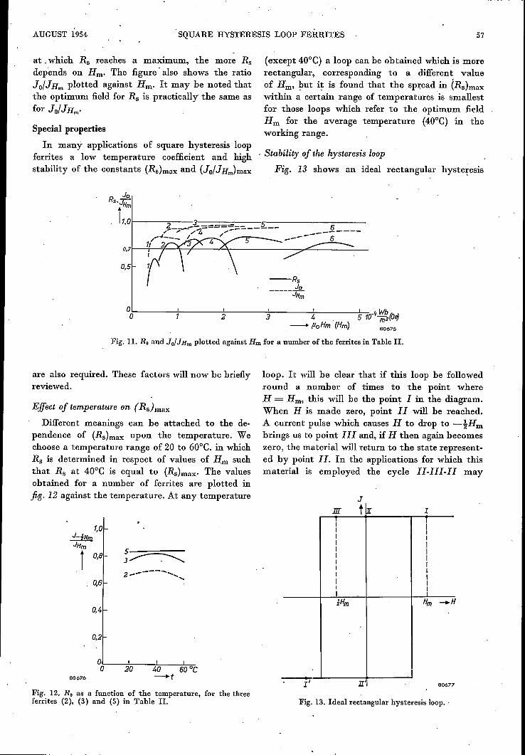
As explained above, the squareness ratio RB of ahysteresis loop is a function of the maximum fieldstrength Hm at which the loop is measured. Fig. 11shows Rs as a function of Hm for the ferrites listedin Table 11. It is seen that the lower the field strength
b
Fig. 10. Photo-micrographsofpolishedsurfaces(magn.400 x). a) FerriteNo. 3 (Table11).b) FerroxcubelVA. P = 0.09.
AUGUST 1954. SQUARE HYSTERESIS LOOP FERRITES 57
JoRS'JHm
. 11.01---....,.---?------- --------:~--
°0):;----t----2±----3~---4-!-----~5""7.10-lf ~~(O~---+ PoHm ' (Hm) 80675
Fig. 11. RB and JolJHm plotted against Hm for a number of the ferrites in Table II.
at .which Rs reaches a maximum, the more Rsdepends on Hm. The figure' also shows the ratioJO/JHm plotted against Hill' It may be noted thatthe optimum field for Rs is practically the same asfor JO/JHm'
Special properties
In many applications of square hysteresis loopferrites a low temperature coefficient and highstability of the constants (Rs)max and (Jo!J Hm)max
0.5
are also required. These factors will now be brieflyreviewed.
Effect of temperature on (Rs}max
Different meanings can be attached to the de-pendence of (Rs)max upon the temperature. Wechoose a temperature range of 20 to 60°C. in whichRs is determined in respect of values of Hm suchthat R; at 40°C is equal to (Rs)max. The valuesobtained for a number of ferrites are plotted infig. 12 against the temperature. At any temperature
5---=---3~2------ ...................
0,4
0,2
80676
Fig. 12. RB as a function of the temperature, for the threeferrites (2), (3) and (5) in Table II.
(except 40°C) a loop can be obtained which is morerectangular, corresponding to a different valueof Hm, but it is found that the spread in (Rs)maxwithin a certain range of temperatures is smallestfor those loops which refer to the optimum fieldHm for the average temperature (40°C) in theworking range.
. Stability .of the hysteresis loop
Fig. 13 shows an ideal rectangular hysteresis
--RsJo
----- JHm
loop. It will be clear that if this loop be followedround a number of times to the point whereH = Hm, this will he the point I in the diagram.When H is made zero, point II will be reached.A current pulse which causes H to drop to -tHmbrings us to point In and, if H then again becomeszero, the material will return to the state reprosent-ed by point II. In the applications for which thismaterial is employed the cycle IJ-In-IJ may
J
III tl!, 1
I II II II II II II II II II I
1 ilHm Hm _H
l' 11' 80677
Fig. 13. Ideal rectangular hysteresis loop..

58 PHILIPS TECHNICAL REVIEW VOL. 16, No. 2
occur many times before a pulse of magnitude- Hm arrives to bring the material into conditionI' and then II', i.e. to reverse the sign of themagnetization.
How far the non-ideal available materials approx-imate to this behaviour may be gathered fromfig. 14. This shows one half of the hysteresis loopcorresponding to the optimum squareness ratiofor one quality of ferrite. The point I was measuredafter the fie~d HiD. had gone through a number of
~_rO~5t-----~0------~O~.5~--~~~0~~-~W~m2~~-tfloHm -!loH(ff) f'oHm
I '
-fWb2000 to ~(gauss)J(4lfI)
Î1500
1000
500
Fig. 14. Hysteresis loop of ferrite No.2 (see Table II) when thefield is varied a number of times from H = Hm to H = -~Hm.
cycles. When Hm is removed the point 11 is reached.An opposing field -tH~ gives point III and,when this in turn is removed, a point IVis reachedwhich is lower than 11. The variation of pointsI - IV when the cycle I-Il-III-IV is completed anumber of times has also been investigated. FerriteNo. 2 in Table II was used for this purpose. Itwas,found that after a large number of cycles of thesubsidiary loop I-II-III-IV, the induction at pointI had dropped by less than 1%. Point Il remainedconstant within experimental error; point III rose:the corresponding induction value may increase bymore than 5%. Point IV also rose considerably.The final situation is that the subsidiary loop. hasmoved to the position shown by the broken linein fig. 14. Clearly, the squareness ratio Rs doesnot diminish but even increases, in this case from0.76 to 0.81.
60684
Summary. For certain purposes (computing machines, switchingelements) cores of magnetically soft material (i.e. with smallcoercive force) are required, having alinost rectangularhysteresis loops. Ferrites fulfil these requirements and alsohave the advantage ,that eddy currents and other losses areonly small when the field is varied rapidly. The shape of thehysteresis loop of ferrites is determined by the nature of theanisotropy governing the direction of the magnetizationvector (crystal, stress or shape anisotropy). Pronounced crystalanisotropy is an advantage (and with it the accompanyinglow initial permeability /-ti), but it should not be so high thatthe coercive force becomes too great. In order to minimize theother kinds of anisotropy, internal strain and porosity shouldbe avoided. A number of suitable ferrites especially developedfor the purposes mentioned above are described and theirproperties enumerated.
MIRROR CAMERAS FOR GENERAL X-RAY DIAGNOSTICS
by W. HOND lUS BOLDINGH. 778.33: 771.31: 616·073.75
The use of fluorography is becoming more and more common and is now al§.o employedin general X-ray diagnostics. Attempts to minimize the dosage to which the patient is exposedduring this type of examination have developed along two quite separate lines, namely, theimprovement of optical efficiency in photographic systems, and the use of electronic aids(e.g. the X-ray image iniensifier} to increase the image luminance. It is difficult at the presentstage to predict the ultimate relationship between the two methods; the former, however, has nowattained a considerable measure of perfection. The present article describes some of the latestdesigns of the fluorographic cameras used.
Fluorography, that is, the photographing offluorescent X-ray images with the aid of a camerainstead of by direct contact with a film, wasoriginally developed for mass chest survey. Themerits of the method as applièd to this particularbranch of diagnostics have been discussed fully inearlier issues of this Review 1) 2). All that we need
recall here is that documentation is thus achievedwithout undue expense of film and filing space, and
1) A. Bouwers and G. C. E. Burger, X-ray photographywith the camera, Philips tech. Rev. 5, 258-263, 1940.
2) H. J. di Giovanni, W. Kes and K. Lowitzsch, A transport-able X-ray apparatus for mass chest survey, Philips tech.Rev. 10, 105-113, 1948/1949.