Embed Size (px)
Citation preview
REHABILITATON OF KALATUWAWA & LABUGAMA WATER TREATMENT PLANT
PROJECTS
Contract No. P&P/WS/HUN/LABUGAMA/2010/01
CONDITIONAL SURVEY LAB-CO-IMP-DOC-CIW-002_Rev.01
WATERWORKS OF BUDAPEST PLC
DATE: 20TH OF DECEMBER 2013 Revision 01
REHABILITATON OF LABUGAMA AND KALATUWAWA WATER TREATMENT PLANTS
CONDITIONAL SURVEY LAB-CO-IMP-DOC-CIW-002_Rev01 1
Contents 1. Introduction .......................................................................................................................................... 5
2. Location ................................................................................................................................................. 7
3. Raw Water Source ................................................................................................................................. 9
4. Labugama Gravity Dam ....................................................................................................................... 10
5. Spillway ............................................................................................................................................... 12
6. Intake Structure .................................................................................................................................. 15
7. Aeration, Sedimentation and Clarifier ................................................................................................ 21
8. Security hut near the clarifier tank ..................................................................................................... 29
9. Filters ................................................................................................................................................... 31
10. Clear water Reservoir ...................................................................................................................... 38
11. Backwash water pump room .......................................................................................................... 41
12. Chemical Building ............................................................................................................................ 44
13. Backwash water tank ...................................................................................................................... 51
14. Ari blower room .............................................................................................................................. 54
15. Generator Room ............................................................................................................................. 54
16. Administration Building .................................................................................................................. 57
17. Laboratory Room ............................................................................................................................ 59
18. Tools Room ..................................................................................................................................... 61
19. Workshops and Garage ................................................................................................................... 64
20. Security Officer’s Rest Room ........................................................................................................... 67
21. Officer’s Rest Room 01 .................................................................................................................... 70
22. Store Building .................................................................................................................................. 72
23. Officer’s Rest Room 02 .................................................................................................................... 72
24. Access Bridge .................................................................................................................................. 74
25. General Premises ............................................................................................................................ 76
26. Main Entrance ................................................................................................................................. 79
REHABILITATON OF LABUGAMA AND KALATUWAWA WATER TREATMENT PLANTS
CONDITIONAL SURVEY LAB-CO-IMP-DOC-CIW-002_Rev01 2
Table of Figures
Figure 1-1 - Treatment Plant Overview ......................................................................................................... 6Figure 2-1 - Location of Labugama Treatment Plant .................................................................................... 7Figure 2-2 - Topography of Western Province .............................................................................................. 8Figure 3-1 - Labugama Reservoir ................................................................................................................ 10Figure 4-1 - Labugama Dam & Reservoir .................................................................................................... 11Figure 4-2 - Walkway along dam ................................................................................................................. 12Figure 5-1 - Spillway .................................................................................................................................... 13Figure 5-2 - Water leaks from the beads .................................................................................................... 14Figure 5-3 - Wire gate with rust .................................................................................................................. 14Figure 5-4 - Damaged Handrails .................................................................................................................. 15Figure 6-1 - Intake Well ............................................................................................................................... 16Figure 6-2 - Steel grating in walkway with worn off protective paint ........................................................ 16Figure 6-3 - Lifting equipment not functioning in its duty .......................................................................... 17Figure 6-4 - Intake drywell with damage tiles and unsafe ladder ............................................................... 17Figure 6-5 - Intake drywell with damaged tiles ........................................................................................... 18Figure 6-6 - Valve controlling unit with decayed surface paint .................................................................. 18Figure 6-7 - Intake wet well with damage tile ............................................................................................ 19Figure 6-8 - Intake wet well with damage tile surfacing ............................................................................. 19Figure 6-9 - Handrail with decayed surface paint ....................................................................................... 20Figure 6-10 - Bridge connecting the Intake structure ................................................................................. 20Figure 7-1- Aeration Unit ............................................................................................................................ 22Figure 7-2 - Raw water inlet pipes .............................................................................................................. 23Figure 7-3 - Unsafe Stairway ....................................................................................................................... 23Figure 7-4 - Sedimentation and Clarifier ..................................................................................................... 24Figure 7-5 - Cable trays ............................................................................................................................... 24Figure 7-6 - Handrail with rusted base plate .............................................................................................. 25Figure 7-7 - Overflow channel with decayed dislocated metal covers ....................................................... 25Figure 7-8 - Working platform with decayed surface paint ........................................................................ 26Figure 7-9 - Settled water tank ................................................................................................................... 26Figure 7-10 - Vegetation in fissured ............................................................................................................ 27Figure 7-11 - Sludge removing pipes and peel off pain on external wall .................................................... 27Figure 7-12 - Access ladder with decayed steps ......................................................................................... 28Figure 7-13 - Access stairway ...................................................................................................................... 28Figure 7-14 - Steel step decayed ................................................................................................................. 29Figure 8-1 - Security hut .............................................................................................................................. 30Figure 8-2 - Damaged electrical fittings ...................................................................................................... 30Figure 9-1 - Filter building ........................................................................................................................... 31

REHABILITATON OF LABUGAMA AND KALATUWAWA WATER TREATMENT PLANTS
CONDITIONAL SURVEY LAB-CO-IMP-DOC-CIW-002_Rev01 3
Figure 9-2 - Crack on the filter building external wall ................................................................................. 32Figure 9-3 - Filter operating system ............................................................................................................ 32Figure 9-4 - Water leaks from the pump .................................................................................................... 33Figure 9-5 – Roof structure ......................................................................................................................... 33Figure 9-6 - Cracks appears on the construction joints in floor .................................................................. 34Figure 9-7 - Electrical fittings need replacement ........................................................................................ 34Figure 9-8 - Handrail in filter building need thorough cleaning .................................................................. 35Figure 9-9 - Filter not in use ........................................................................................................................ 35Figure 9-10 - Access Concrete Stairway need cleaning and painting ......................................................... 36Figure 9-11 - Access concrete stairway need repair work .......................................................................... 36Figure 9-12 - Structural steel beams supporting the mezzanine floor ....................................................... 37Figure 9-13 - Filter gallery ........................................................................................................................... 37Figure 9-14 - Access concrete stairway appeared to have crack ................................................................ 38Figure 10-1 - Clear water tank top slab ....................................................................................................... 39Figure 10-2 - Post lime solution unit ........................................................................................................... 39Figure 10-3 - Overflow channel cracks ........................................................................................................ 40Figure 10-4 - Ventilation units in the top slab ............................................................................................ 40Figure 10-5 - Unsafe electrical supply ......................................................................................................... 41Figure 11-1 - Backwash pumping room ...................................................................................................... 42Figure 11-2 - Structural steel beam supporting roof slab is not up to serviceable level ............................ 42Figure 11-3 - Damaged lintel ....................................................................................................................... 43Figure 11-4 - Cracks on the interior wall ..................................................................................................... 43Figure 11-5 - Back wash inlet pipes ............................................................................................................. 44Figure 12-1 - Chemical building .................................................................................................................. 45Figure 12-2 - Deteriorated structural steel ................................................................................................. 45Figure 12-3 - Pipe line network ................................................................................................................... 46Figure 12-4 - Water tank with cracked wall ................................................................................................ 46Figure 12-5 - Pipe trench need cleaning and it top cover ........................................................................... 47Figure 12-6 - Chemical storing area ............................................................................................................ 47Figure 12-7 - Steel stairway with damaged steps ....................................................................................... 48Figure 12-8 - Lime storing tank with lime deposit ...................................................................................... 48Figure 12-9 - Mechanical equipment with rusted casing ........................................................................... 49Figure 12-10 - Poly aluminium chloride tank .............................................................................................. 49Figure 12-11 - Leaks in the pipe network ................................................................................................... 50Figure 12-12 - Pipe network not in proper order ....................................................................................... 50Figure 12-13 - Door paint fade due to sun burn ......................................................................................... 51Figure 13-1 – backwash water tank ............................................................................................................ 52Figure 13-2 - Steel roof trusses have peel of it painting ............................................................................. 52Figure 13-3 - Unsafe access ladder ............................................................................................................. 53Figure 13-4 - Backwash water tank interior ................................................................................................ 53Figure 14-1 - Air blower room ..................................................................................................................... 54

REHABILITATON OF LABUGAMA AND KALATUWAWA WATER TREATMENT PLANTS
CONDITIONAL SURVEY LAB-CO-IMP-DOC-CIW-002_Rev01 4
Figure 15-1 - Generator room ..................................................................................................................... 55Figure 15-2 – Generator .............................................................................................................................. 55Figure 15-3 - Damaged painting and cracks on the interior wall ................................................................ 56Figure 15-4 – Water leaks from the existing roof slab ................................................................................ 56Figure 16-1 - Admin building front view ..................................................................................................... 57Figure 16-2 - Front drain with vegetation ................................................................................................... 58Figure 16-3 - Admin building inside improper electrical system ................................................................ 58Figure 16-4 - Admin building inside floor has been crack ........................................................................... 59Figure 17-1 - Laboratory room .................................................................................................................... 60Figure 17-2 - Loose painting due to moisture effect .................................................................................. 60Figure 18-1 - Tools room ............................................................................................................................. 61Figure 18-2 - Damaged roof covering and rusted structural roof steel ...................................................... 62Figure 18-3 - Inside the tool room .............................................................................................................. 63Figure 18-4 - Tools storing rack ................................................................................................................... 63Figure 19-1 - Workshop and Garage ........................................................................................................... 64Figure 19-2 – Workshop building with rusted roof trusses and unserviceable ventilation elements ........ 65Figure 19-3 - Garage showing the damaged plaster with rusted unserviceable roof trusses .................... 66Figure 20-1 - Security officer’s rest room ................................................................................................... 67Figure 20-2 - Roof structure ........................................................................................................................ 68Figure 20-3 - Unsafe electrical fitting .......................................................................................................... 68Figure 20-4 - Decayed timber frame ........................................................................................................... 69Figure 20-5 - Damaged plaster in the wall .................................................................................................. 70Figure 21-1 - Officer building inside ............................................................................................................ 71Figure 21-2 - Officer's rest room toilet ....................................................................................................... 71Figure 22-1 - Store building ......................................................................................................................... 72Figure 23-1 - Officer's rest room02 ............................................................................................................. 73Figure 23-2 - Officers rest room 02 ............................................................................................................. 74Figure 24-1 -Bailey bridge ........................................................................................................................... 75Figure 24-2 - Structural truss beam ............................................................................................................ 75Figure 24-3 - Deteriorated steel trusses ..................................................................................................... 76Figure 25-1 - Pipe stored store building ...................................................................................................... 77Figure 25-2 - Places where the handrail is utmost impotence ................................................................... 78Figure 25-3 - Defects in the road network .................................................................................................. 78Figure 25-4 - Hazarders slope ..................................................................................................................... 79Figure 26-1 - Main access bridge ................................................................................................................ 80Figure 26-2 - Security hut ............................................................................................................................ 80

REHABILITATON OF LABUGAMA AND KALATUWAWA WATER TREATMENT PLANTS
CONDITIONAL SURVEY LAB-CO-IMP-DOC-CIW-002_Rev01 5
1. Introduction
With the colonization of Sri Lanka by foreign nations, the dynamic of the local economy was rapidly transformed. Sri Lanka had a village based agricultural economy, where local produce was just enough to satisfy the needs of the local community. But with the colonization large scale export became the main priority of the economy. In order to fulfil this objective large scale infrastructure projects were implemented and the local communities of Sri Lanka slowly became acquainted with urbanisation.
What used to be a city mainly engaged with fisheries, cinnamon farming and small scale trade quickly transformed into a commercial metropolis. Because of the strategic location of Colombo commercial trade blossomed and the infrastructure was developed in order to sustain the growing population. The Colombo district currently boasts of a population of over 2.3 million residents and a population growth rate of 2.42%. The demand for potable water is steadily increasing with the rising population.
People of Colombo used water wells in the past to satisfy their water needs. But with the rapid urbanisation and industrialisation of the area, sufficient land space and uncontaminated groundwater has been hard to come by for the general population. Therefore it is essential that their demands are met through water bearing pipes.
As the Government of Sri Lanka it is their responsibility to maintain an adequate supply to meet the demands population of the people. In order to increase the supply of drinkable water and to maintain Sri Lankan Standards for water quality new upgrades and new water sources need to be harnessed. Under this development plan, the Labugama and Kalatuwawa Water Treatment Plants were chosen to be upgraded.
The Labugama Water Treatment Plant being the oldest treatment plant in Sri Lanka was built in 1886 in British colonial era with the objective of providing the people of Colombo clean drinking water. Together with its adjacent water treatment plant at Kalatuwawa, they account for considerable portion of the region’s water demand. The Labugama Water Treatment Plant is a pristine work of engineering. It has served the people of Sri Lanka for nearly 130 years and is still capable of putting out a noteworthy output.
The Labugama Water Treatment Plant was designed to have a nominal production of 60,000 m3 per day, but with its extensive years of service its capacity has diminished to a nominal output of 40,000 m3 per day. It is not just the capacity that has been affected over time. Working conditions and general cleanliness have also been deteriorated without sufficient funds for maintenance despite the fact that the recently carried out renovation work by the Japanese Construction organization. The technology utilised at the treatment plant is also outdated since it was built in ancient time. The network of valves and gates that divert the water flow has to be controlled manually. The treatment plant also uses a laboratory testing as its mean of monitoring the water quality. These factors make the daily operation of the facility tedious and costly.
REHABILITATON OF LABUGAMA AND KALATUWAWA WATER TREATMENT PLANTS
CONDITIONAL SURVEY LAB-CO-IMP-DOC-CIW-002_Rev01 6
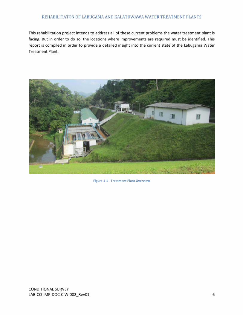
This rehabilitation project intends to address all of these current problems the water treatment plant is facing. But in order to do so, the locations where improvements are required must be identified. This report is compiled in order to provide a detailed insight into the current state of the Labugama Water Treatment Plant.
Figure 1-1 - Treatment Plant Overview
REHABILITATON OF LABUGAMA AND KALATUWAWA WATER TREATMENT PLANTS
CONDITIONAL SURVEY LAB-CO-IMP-DOC-CIW-002_Rev01 7
2.
Location
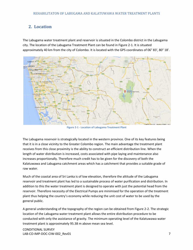
The Labugama water treatment plant and reservoir is situated in the Colombo district in the Labugama city. The location of the Labugama Treatment Plant can be found in Figure 2-1. It is situated approximately 40 km from the city of Colombo. It is located with the GPS coordinates of 0
6° 83', 80° 18'.
Figure 2-1 - Location of Labugama Treatment Plant
The Labugama reservoir is strategically located in the western province. One of its key features being that it is in a close vicinity to the Greater Colombo region. The main advantage the treatment plant receives from this close proximity is the ability to construct an efficient distribution line. When the length of water distribution is increased, costs associated with pipe laying and maintenance also increases proportionally. Therefore much credit has to be given for the discovery of both the Kalatuwawa and Labugama catchment areas which has a catchment that provides a suitable grade of raw water.
Much of the coastal area of Sri Lanka is of low elevation, therefore the altitude of the Labugama reservoir and treatment plant has led to a sustainable process of water purification and distribution. In addition to this the water treatment plant is designed to operate with just the potential head from the reservoir. Therefore necessity of the Electrical Pumps are minimised for the operation of the treatment plant thus helping the country’s economy while reducing the unit cost of water to be used by the general public.
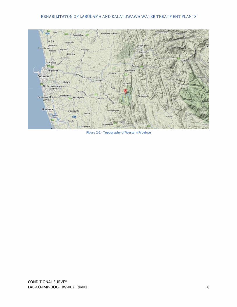
A general understanding of the topography of the region can be obtained from Figure 2-2. The strategic location of the Labugama water treatment plant allows the entire distribution procedure to be conducted with only the assistance of gravity. The minimum operating level of the Kalatuwawa water treatment plant is approximately 95.38 m above mean sea level.
REHABILITATON OF LABUGAMA AND KALATUWAWA WATER TREATMENT PLANTS
CONDITIONAL SURVEY LAB-CO-IMP-DOC-CIW-002_Rev01 8
Figure 2-2 - Topography of Western Province
REHABILITATON OF LABUGAMA AND KALATUWAWA WATER TREATMENT PLANTS
CONDITIONAL SURVEY LAB-CO-IMP-DOC-CIW-002_Rev01 9
3.
Raw Water Source
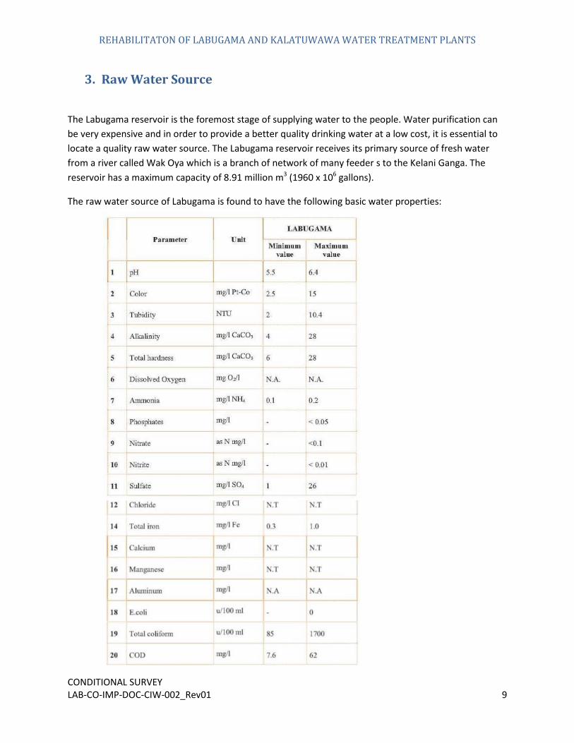
The Labugama reservoir is the foremost stage of supplying water to the people. Water purification can be very expensive and in order to provide a better quality drinking water at a low cost, it is essential to locate a quality raw water source. The Labugama reservoir receives its primary source of fresh water from a river called Wak Oya which is a branch of network of many feeder s to the Kelani Ganga. The reservoir has a maximum capacity of 8.91 million m3 (1960 x 106 gallons).
The raw water source of Labugama is found to have the following basic water properties:
REHABILITATON OF LABUGAMA AND KALATUWAWA WATER TREATMENT PLANTS
CONDITIONAL SURVEY LAB-CO-IMP-DOC-CIW-002_Rev01 10
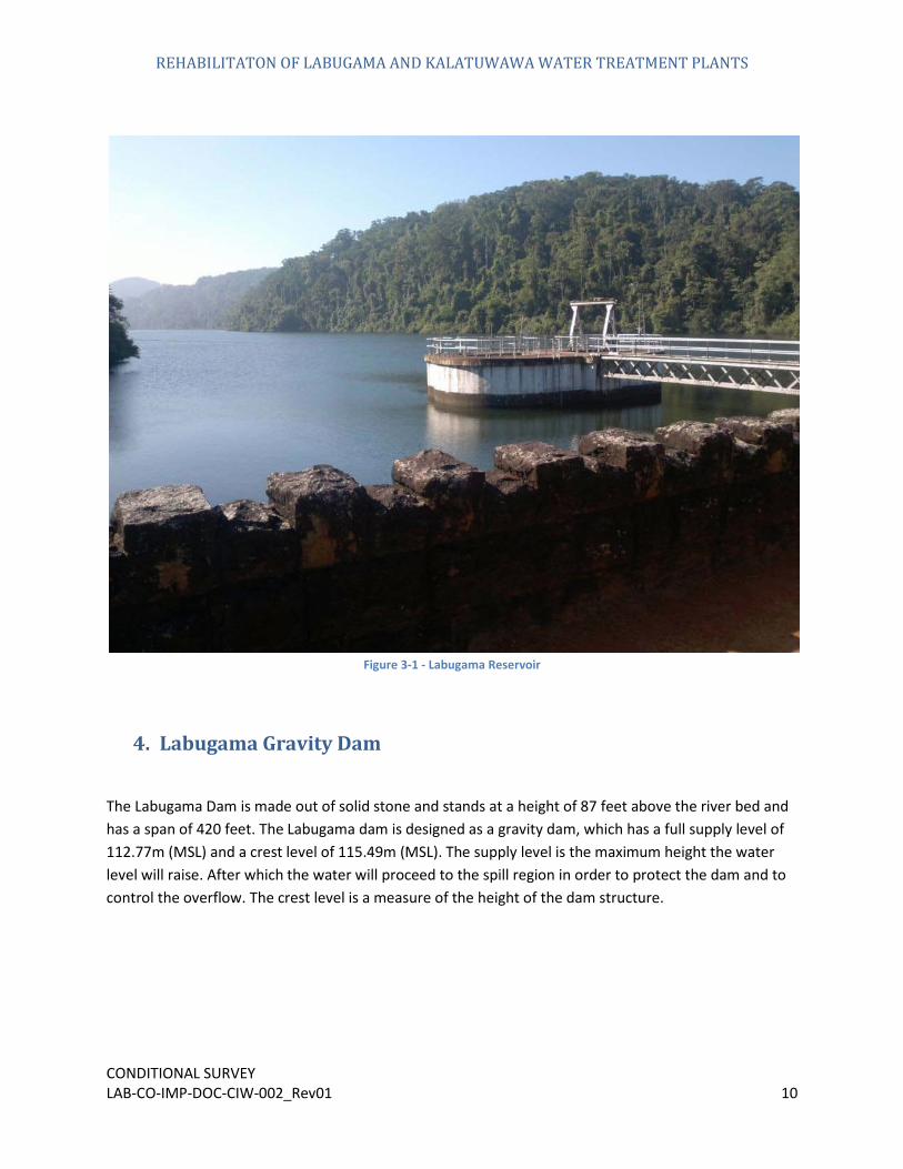
Figure 3-1 - Labugama Reservoir
4.
Labugama Gravity Dam
The Labugama Dam is made out of solid stone and stands at a height of 87 feet above the river bed and has a span of 420 feet. The Labugama dam is designed as a gravity dam, which has a full supply level of 112.77m (MSL) and a crest level of 115.49m (MSL). The supply level is the maximum height the water level will raise. After which the water will proceed to the spill region in order to protect the dam and to control the overflow. The crest level is a measure of the height of the dam structure.
REHABILITATON OF LABUGAMA AND KALATUWAWA WATER TREATMENT PLANTS
CONDITIONAL SURVEY LAB-CO-IMP-DOC-CIW-002_Rev01 11
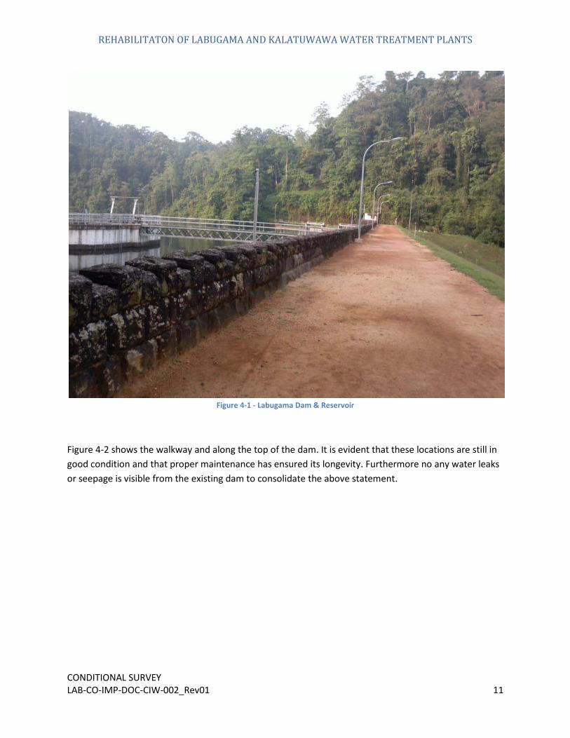
Figure 4-1 - Labugama Dam & Reservoir
Figure 4-2 shows the walkway and along the top of the dam. It is evident that these locations are still in good condition and that proper maintenance has ensured its longevity. Furthermore no any water leaks or seepage is visible from the existing dam to consolidate the above statement.

REHABILITATON OF LABUGAMA AND KALATUWAWA WATER TREATMENT PLANTS
CONDITIONAL SURVEY LAB-CO-IMP-DOC-CIW-002_Rev01 12
Figure 4-2 - Walkway along dam
5.
Spillway
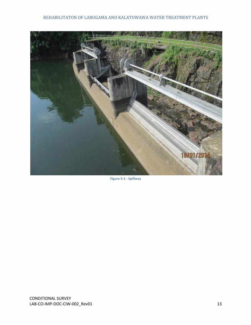
Figure 4-2 shows the spillway of over running type with steel wire gates for dam is designed to let excess water overflow in a controlled manner when the water level of the reservoir exceeds the dams’ maximum bearable capacity. This spillway is opened to natural pound and spilling water will flow back to original steam. Frequent overflow is experiencing during a year from this structure.
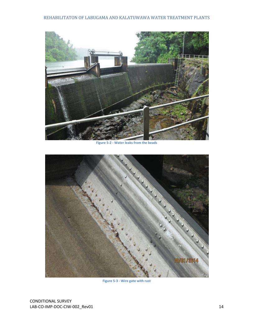
The premises surrounding the spillway have built up vegetation over time and are in need of thorough clearing. Spillway doors leak water from its perimeter beads. The handrails, ladders, gates and assembly condition are functioning well but some parts of the external protective paint have been damaged and worn off.
REHABILITATON OF LABUGAMA AND KALATUWAWA WATER TREATMENT PLANTS
CONDITIONAL SURVEY LAB-CO-IMP-DOC-CIW-002_Rev01 13
Figure 5-1 - Spillway
REHABILITATON OF LABUGAMA AND KALATUWAWA WATER TREATMENT PLANTS
CONDITIONAL SURVEY LAB-CO-IMP-DOC-CIW-002_Rev01 14
Figure 5-2 - Water leaks from the beads
Figure 5-3 - Wire gate with rust

REHABILITATON OF LABUGAMA AND KALATUWAWA WATER TREATMENT PLANTS
CONDITIONAL SURVEY LAB-CO-IMP-DOC-CIW-002_Rev01 15
Figure 5-4 - Damaged Handrails
6.
Intake Structure
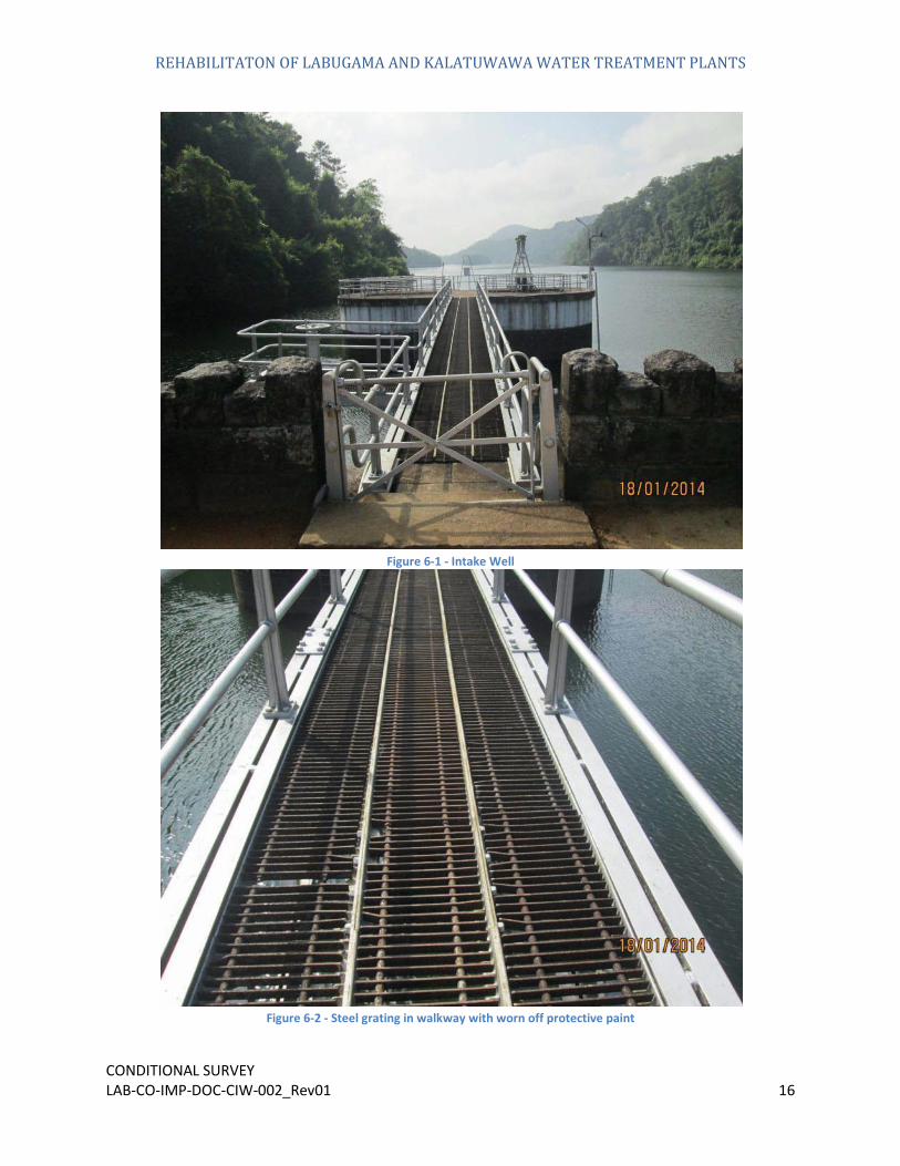
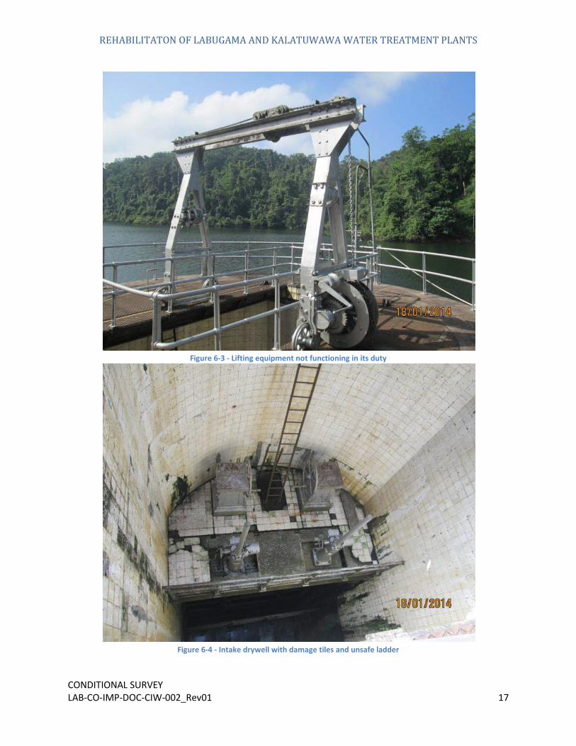
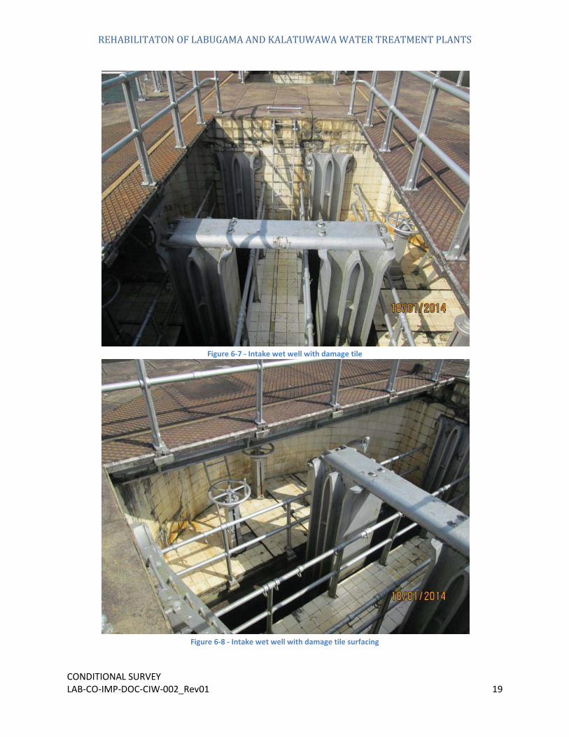
As shown in Figure 6-4 - Intake drywell with damage tiles and unsafe ladder and Figure 6-5 - Intake drywell with damaged tiles, the nature of the wells has greatly deteriorated in it appearance. The primer and anticorrosion paint has worn off with the time and this process has been accelerated by the adverse weather that it exposed to, which has led to the decay and corrosion of the metallic components. The tiles which run along the interior surface of the wells have been damaged considerably and cracked from the wall over time have also propagated and there is a large build up of algae in the wells. Such characteristics of the current wells have led to a reduced functionality and an unsafe working environment to the people working with these units.
Intake structure in the Labugama plant comprises with two wells i.e. wet well and dray well. Inside walls of both wells has finished with wall tiles. The most of the tile area above has decayed and damaged. Cracks are appeared in several locations and water leaks also seen from these cracked locations in dry well to the inside.
REHABILITATON OF LABUGAMA AND KALATUWAWA WATER TREATMENT PLANTS
CONDITIONAL SURVEY LAB-CO-IMP-DOC-CIW-002_Rev01 16
Figure 6-1 - Intake Well
Figure 6-2 - Steel grating in walkway with worn off protective paint
REHABILITATON OF LABUGAMA AND KALATUWAWA WATER TREATMENT PLANTS
CONDITIONAL SURVEY LAB-CO-IMP-DOC-CIW-002_Rev01 17
Figure 6-3 - Lifting equipment not functioning in its duty
Figure 6-4 - Intake drywell with damage tiles and unsafe ladder

REHABILITATON OF LABUGAMA AND KALATUWAWA WATER TREATMENT PLANTS
CONDITIONAL SURVEY LAB-CO-IMP-DOC-CIW-002_Rev01 18
Figure 6-5 - Intake drywell with damaged tiles
Figure 6-6 - Valve controlling unit with decayed surface paint
REHABILITATON OF LABUGAMA AND KALATUWAWA WATER TREATMENT PLANTS
CONDITIONAL SURVEY LAB-CO-IMP-DOC-CIW-002_Rev01 19
Figure 6-7 - Intake wet well with damage tile
Figure 6-8 - Intake wet well with damage tile surfacing

REHABILITATON OF LABUGAMA AND KALATUWAWA WATER TREATMENT PLANTS
CONDITIONAL SURVEY LAB-CO-IMP-DOC-CIW-002_Rev01 20
Figure 6-9 - Handrail with decayed surface paint
Figure 6-10 - Bridge connecting the Intake structure
REHABILITATON OF LABUGAMA AND KALATUWAWA WATER TREATMENT PLANTS
CONDITIONAL SURVEY LAB-CO-IMP-DOC-CIW-002_Rev01 21
7.
Aeration, Sedimentation and Clarifier
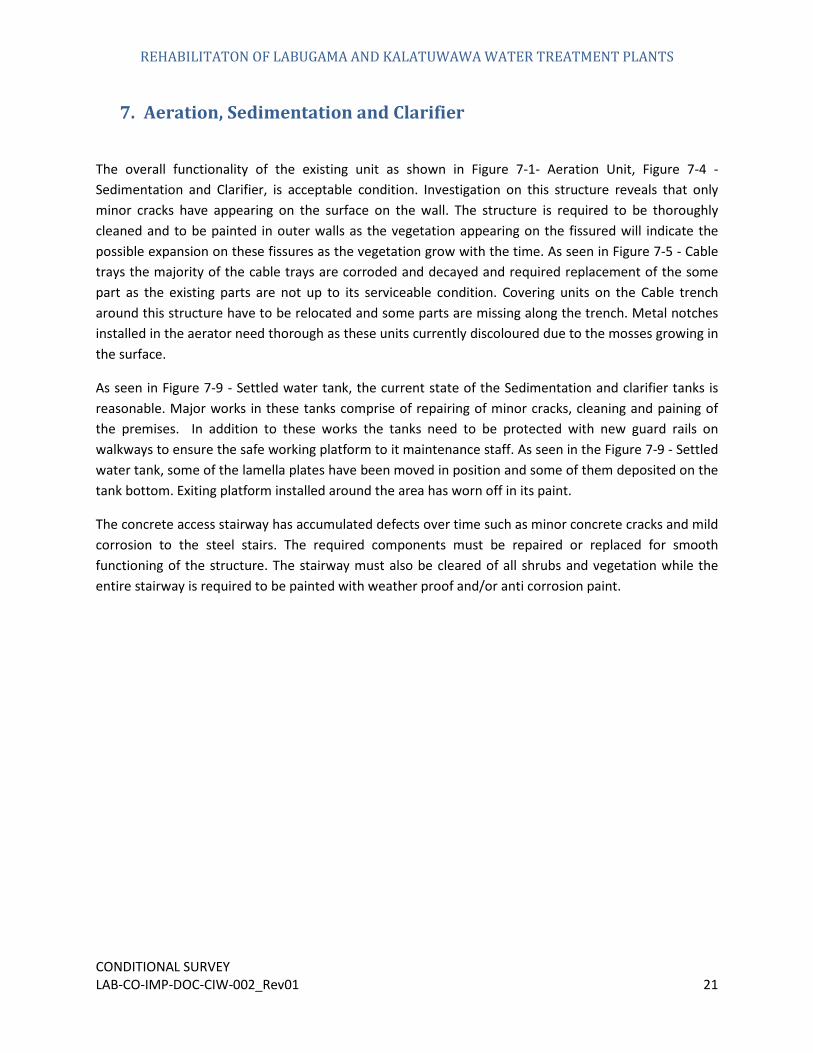
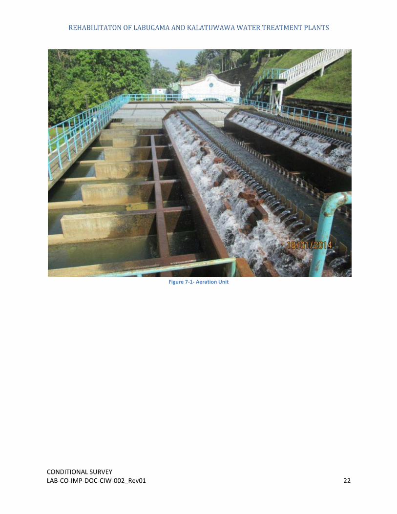
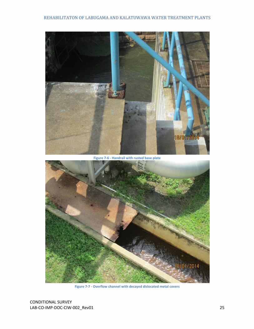
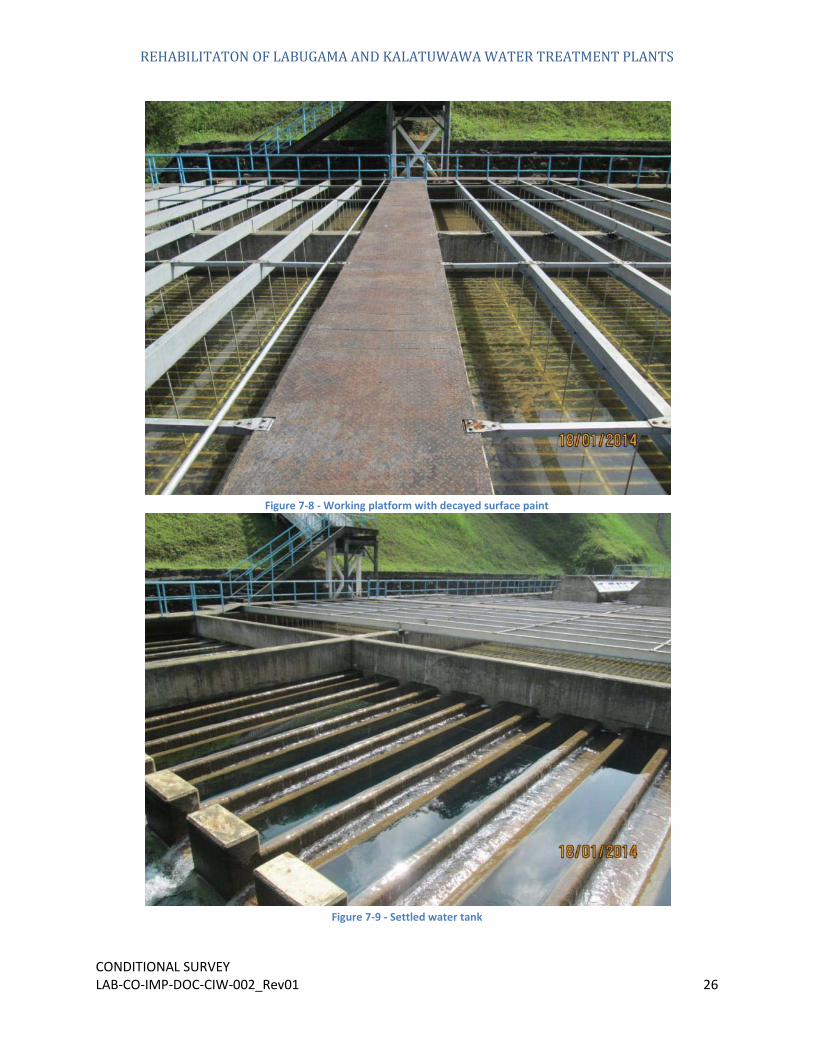
The overall functionality of the existing unit as shown in Figure 7-1- Aeration Unit, Figure 7-4 - Sedimentation and Clarifier, is acceptable condition. Investigation on this structure reveals that only minor cracks have appearing on the surface on the wall. The structure is required to be thoroughly cleaned and to be painted in outer walls as the vegetation appearing on the fissured will indicate the possible expansion on these fissures as the vegetation grow with the time. As seen in Figure 7-5 - Cable trays the majority of the cable trays are corroded and decayed and required replacement of the some part as the existing parts are not up to its serviceable condition. Covering units on the Cable trench around this structure have to be relocated and some parts are missing along the trench. Metal notches installed in the aerator need thorough as these units currently discoloured due to the mosses growing in the surface.
As seen in Figure 7-9 - Settled water tank, the current state of the Sedimentation and clarifier tanks is reasonable. Major works in these tanks comprise of repairing of minor cracks, cleaning and paining of the premises. In addition to these works the tanks need to be protected with new guard rails on walkways to ensure the safe working platform to it maintenance staff. As seen in the Figure 7-9 - Settled water tank, some of the lamella plates have been moved in position and some of them deposited on the tank bottom. Exiting platform installed around the area has worn off in its paint.
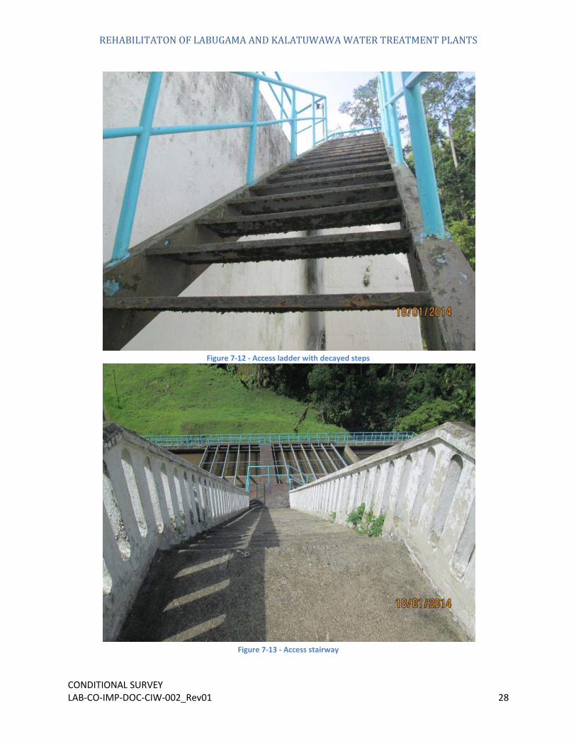
The concrete access stairway has accumulated defects over time such as minor concrete cracks and mild corrosion to the steel stairs. The required components must be repaired or replaced for smooth functioning of the structure. The stairway must also be cleared of all shrubs and vegetation while the entire stairway is required to be painted with weather proof and/or anti corrosion paint.
REHABILITATON OF LABUGAMA AND KALATUWAWA WATER TREATMENT PLANTS
CONDITIONAL SURVEY LAB-CO-IMP-DOC-CIW-002_Rev01 22
Figure 7-1- Aeration Unit

REHABILITATON OF LABUGAMA AND KALATUWAWA WATER TREATMENT PLANTS
CONDITIONAL SURVEY LAB-CO-IMP-DOC-CIW-002_Rev01 23
Figure 7-2 - Raw water inlet pipes
Figure 7-3 - Unsafe Stairway

REHABILITATON OF LABUGAMA AND KALATUWAWA WATER TREATMENT PLANTS
CONDITIONAL SURVEY LAB-CO-IMP-DOC-CIW-002_Rev01 24
Figure 7-4 - Sedimentation and Clarifier
Figure 7-5 - Cable trays
REHABILITATON OF LABUGAMA AND KALATUWAWA WATER TREATMENT PLANTS
CONDITIONAL SURVEY LAB-CO-IMP-DOC-CIW-002_Rev01 25
Figure 7-6 - Handrail with rusted base plate
Figure 7-7 - Overflow channel with decayed dislocated metal covers
REHABILITATON OF LABUGAMA AND KALATUWAWA WATER TREATMENT PLANTS
CONDITIONAL SURVEY LAB-CO-IMP-DOC-CIW-002_Rev01 26
Figure 7-8 - Working platform with decayed surface paint
Figure 7-9 - Settled water tank

REHABILITATON OF LABUGAMA AND KALATUWAWA WATER TREATMENT PLANTS
CONDITIONAL SURVEY LAB-CO-IMP-DOC-CIW-002_Rev01 27
Figure 7-10 - Vegetation in fissured
Figure 7-11 - Sludge removing pipes and peel off pain on external wall
REHABILITATON OF LABUGAMA AND KALATUWAWA WATER TREATMENT PLANTS
CONDITIONAL SURVEY LAB-CO-IMP-DOC-CIW-002_Rev01 28
Figure 7-12 - Access ladder with decayed steps
Figure 7-13 - Access stairway

REHABILITATON OF LABUGAMA AND KALATUWAWA WATER TREATMENT PLANTS
CONDITIONAL SURVEY LAB-CO-IMP-DOC-CIW-002_Rev01 29
Figure 7-14 - Steel step decayed
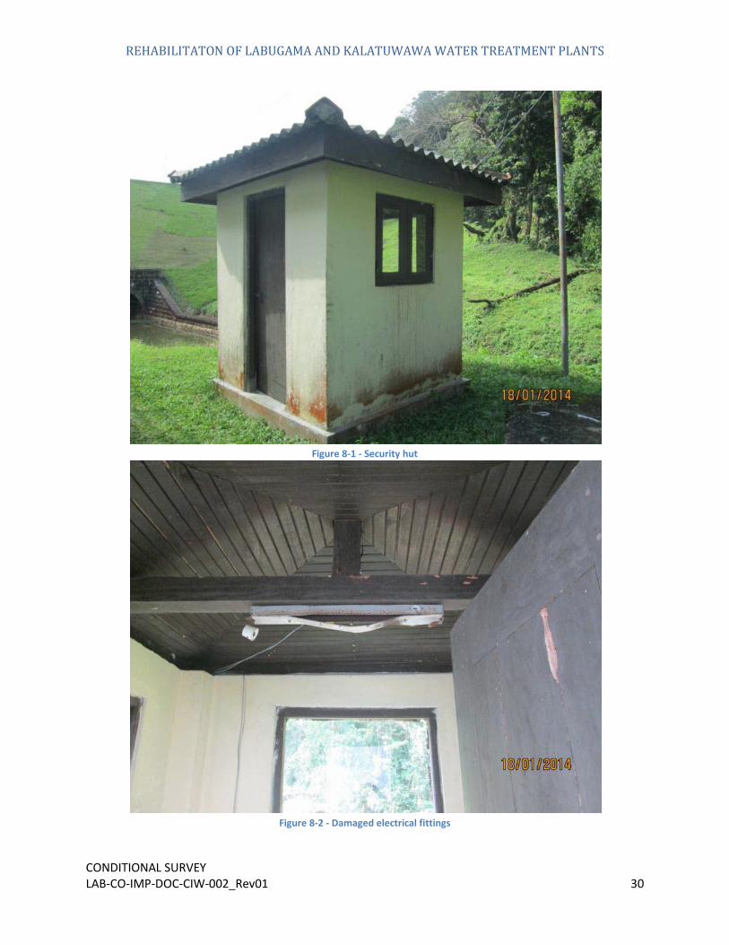
8. The structure is inacceptable condition but mosses have grown up on the bottom part of the external wall. Doors and window are in good condition but the paint has faded due to the direct sun burn.
Security hut near the clarifier tank
REHABILITATON OF LABUGAMA AND KALATUWAWA WATER TREATMENT PLANTS
CONDITIONAL SURVEY LAB-CO-IMP-DOC-CIW-002_Rev01 30
Figure 8-1 - Security hut
Figure 8-2 - Damaged electrical fittings

REHABILITATON OF LABUGAMA AND KALATUWAWA WATER TREATMENT PLANTS
CONDITIONAL SURVEY LAB-CO-IMP-DOC-CIW-002_Rev01 31
9. Exiting filter functions is not meeting its design capacity and major repair work has to be carried out in order to bring the system to its design capacity. The overall structural integrity of this building has been maintained except minor crack on the structure. The roof is in prime condition while minor repairs to the walls have to be conducted where cracks have propagated. Paint has chipped in several areas of the existing walls and the structural steel components, and mosses have started to grow where there are leaks appear.
Out of the 15 Nos of sand filters that were initially installed, only 10 are currently in operational condition. The rest are unable to deliver a satisfactory performance due to malfunctioning of the mechanical system and lack of assembling component since the spares are out dated hence reducing its design capacity drastically. There seems to be no large leaks and cracks in the filters but their functionality has decreased over time. Condition of the controlling valves for the filters is also working acceptable. Some of the pipes connections and pump currently in operation in the filtration building shows some leaks due to lack of maintenance.
Filters
Figure 9-1 - Filter building

REHABILITATON OF LABUGAMA AND KALATUWAWA WATER TREATMENT PLANTS
CONDITIONAL SURVEY LAB-CO-IMP-DOC-CIW-002_Rev01 32
Figure 9-2 - Crack on the filter building external wall
Figure 9-3 - Filter operating system

REHABILITATON OF LABUGAMA AND KALATUWAWA WATER TREATMENT PLANTS
CONDITIONAL SURVEY LAB-CO-IMP-DOC-CIW-002_Rev01 33
Figure 9-4 - Water leaks from the pump
Figure 9-5 – Roof structure

REHABILITATON OF LABUGAMA AND KALATUWAWA WATER TREATMENT PLANTS
CONDITIONAL SURVEY LAB-CO-IMP-DOC-CIW-002_Rev01 34
Figure 9-6 - Cracks appears on the construction joints in floor
Figure 9-7 - Electrical fittings need replacement

REHABILITATON OF LABUGAMA AND KALATUWAWA WATER TREATMENT PLANTS
CONDITIONAL SURVEY LAB-CO-IMP-DOC-CIW-002_Rev01 35
Figure 9-8 - Handrail in filter building need thorough cleaning
Figure 9-9 - Filter not in use

REHABILITATON OF LABUGAMA AND KALATUWAWA WATER TREATMENT PLANTS
CONDITIONAL SURVEY LAB-CO-IMP-DOC-CIW-002_Rev01 36
Figure 9-10 - Access Concrete Stairway need cleaning and painting
Figure 9-11 - Access concrete stairway need repair work

REHABILITATON OF LABUGAMA AND KALATUWAWA WATER TREATMENT PLANTS
CONDITIONAL SURVEY LAB-CO-IMP-DOC-CIW-002_Rev01 37
Figure 9-12 - Structural steel beams supporting the mezzanine floor
Figure 9-13 - Filter gallery

REHABILITATON OF LABUGAMA AND KALATUWAWA WATER TREATMENT PLANTS
CONDITIONAL SURVEY LAB-CO-IMP-DOC-CIW-002_Rev01 38
Figure 9-14 - Access concrete stairway appeared to have crack
10.
The underground clear water tank is fully functional and only minor tasks need to be conducted on it. Its interior walls must be cleaned thoroughly in order to clean up the mosses and algae. The land area above the clear water tank should be cleared of all weeds and landscaped to an acceptable standard.
Installed steel pipes on the existing ventilation provision on the top-slab of the Clearwater reservoir have shown up some corroded parts and loos of paint on some sections. Primitive method of post lime mixing unit can be seen, where the exposes pipe system has been use to convey these chemical solution to the clean water. Several access Man-holes to the Clearwater thank is visible and the covering slab of these units is not seems to be fully functional owing to the deterioration of the handling parts of these units.
Minor cracks have been proper gated on the concrete overflow channel which served to convey excess water in the clear water reservoir to the nearby stream.
Clear water Reservoir

REHABILITATON OF LABUGAMA AND KALATUWAWA WATER TREATMENT PLANTS
CONDITIONAL SURVEY LAB-CO-IMP-DOC-CIW-002_Rev01 39
Figure 10-1 - Clear water tank top slab
Figure 10-2 - Post lime solution unit

REHABILITATON OF LABUGAMA AND KALATUWAWA WATER TREATMENT PLANTS
CONDITIONAL SURVEY LAB-CO-IMP-DOC-CIW-002_Rev01 40
Figure 10-3 - Overflow channel cracks
Figure 10-4 - Ventilation units in the top slab

REHABILITATON OF LABUGAMA AND KALATUWAWA WATER TREATMENT PLANTS
CONDITIONAL SURVEY LAB-CO-IMP-DOC-CIW-002_Rev01 41
Figure 10-5 - Unsafe electrical supply
11.
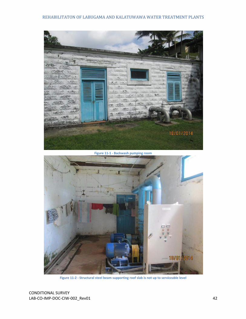
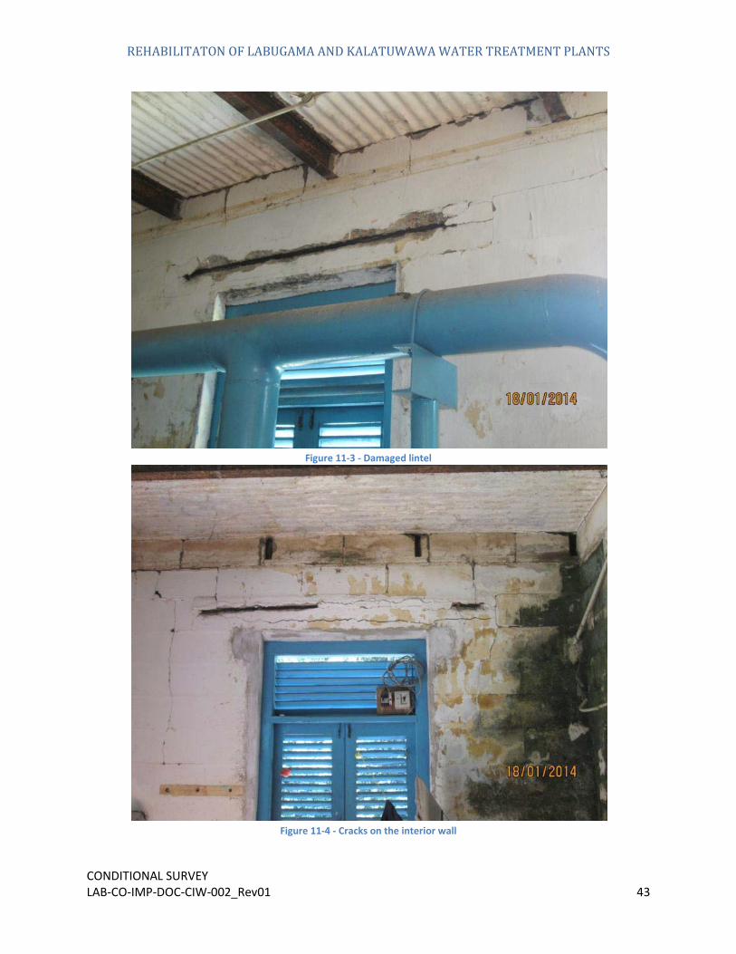
The general condition of the pumping room is not at acceptable level in. Cracks have propagated through its all over the walls. Despite these cracks pose risk to the structural stability they adversely affect to the aesthetic view of the existing structure. In order to get this structure to fully functional level, it is required to carry out major rehabilitation work on the structural element like roof slab, Walls, lintel beam and the ground floor. In addition to this the pump house must be repainted and cleaned. The working condition of the pump is still at acceptable level.
Mosses and algae on the interior wall have grown up, which affect the aesthetic view of the structure in addition to the cracks. Window and door located in the structure is acceptable and some part of the paint has peel off and faded due to the sun burn.
Backwash water pump room
REHABILITATON OF LABUGAMA AND KALATUWAWA WATER TREATMENT PLANTS
CONDITIONAL SURVEY LAB-CO-IMP-DOC-CIW-002_Rev01 42
Figure 11-1 - Backwash pumping room
Figure 11-2 - Structural steel beam supporting roof slab is not up to serviceable level
REHABILITATON OF LABUGAMA AND KALATUWAWA WATER TREATMENT PLANTS
CONDITIONAL SURVEY LAB-CO-IMP-DOC-CIW-002_Rev01 43
Figure 11-3 - Damaged lintel
Figure 11-4 - Cracks on the interior wall

REHABILITATON OF LABUGAMA AND KALATUWAWA WATER TREATMENT PLANTS
CONDITIONAL SURVEY LAB-CO-IMP-DOC-CIW-002_Rev01 44
Figure 11-5 - Back wash inlet pipes
12.
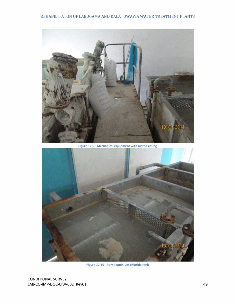
The chemical building and it ME&I equipment was found to be in an overall functional condition. There were no structural damages to the building over time. Cracking of the walls and rusting of the steel framed rood was visible. The reagent mixing chambers were unclean and had lime accumulated around it. The floors were unclean and had mainly chemical residue covering it. Steel walking platform and the hand rail present inside the building have greatly deteriorated owing to the chemicals store within the building.
Roof structure covering the building is acceptable and the rain water gutters and the down pipe have greatly deteriorated over the time. Chlorine storing area is not up to the perfect condition and the water tank near the chlorination building have crack on its wall.
The condition of existing pipe line and the drain system need cleaning and minor repairs.
Chemical Building

REHABILITATON OF LABUGAMA AND KALATUWAWA WATER TREATMENT PLANTS
CONDITIONAL SURVEY LAB-CO-IMP-DOC-CIW-002_Rev01 45
Figure 12-1 - Chemical building
Figure 12-2 - Deteriorated structural steel

REHABILITATON OF LABUGAMA AND KALATUWAWA WATER TREATMENT PLANTS
CONDITIONAL SURVEY LAB-CO-IMP-DOC-CIW-002_Rev01 46
Figure 12-3 - Pipe line network
Figure 12-4 - Water tank with cracked wall

REHABILITATON OF LABUGAMA AND KALATUWAWA WATER TREATMENT PLANTS
CONDITIONAL SURVEY LAB-CO-IMP-DOC-CIW-002_Rev01 47
Figure 12-5 - Pipe trench need cleaning and it top cover
Figure 12-6 - Chemical storing area

REHABILITATON OF LABUGAMA AND KALATUWAWA WATER TREATMENT PLANTS
CONDITIONAL SURVEY LAB-CO-IMP-DOC-CIW-002_Rev01 48
Figure 12-7 - Steel stairway with damaged steps
Figure 12-8 - Lime storing tank with lime deposit
REHABILITATON OF LABUGAMA AND KALATUWAWA WATER TREATMENT PLANTS
CONDITIONAL SURVEY LAB-CO-IMP-DOC-CIW-002_Rev01 49
Figure 12-9 - Mechanical equipment with rusted casing
Figure 12-10 - Poly aluminium chloride tank

REHABILITATON OF LABUGAMA AND KALATUWAWA WATER TREATMENT PLANTS
CONDITIONAL SURVEY LAB-CO-IMP-DOC-CIW-002_Rev01 50
Figure 12-11 - Leaks in the pipe network
Figure 12-12 - Pipe network not in proper order
REHABILITATON OF LABUGAMA AND KALATUWAWA WATER TREATMENT PLANTS
CONDITIONAL SURVEY LAB-CO-IMP-DOC-CIW-002_Rev01 51
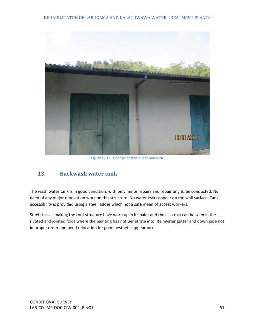
Figure 12-13 - Door paint fade due to sun burn
13.
The wash water tank is in good condition, with only minor repairs and repainting to be conducted. No need of any major renovation work on this structure. No water leaks appear on the wall surface. Tank accessibility is provided using a steel ladder which not a safe mean of access workers.
Steel trusses making the roof structure have worn up in its paint and the also rust can be seen in the riveted and jointed folds where the painting has not penetrate into. Rainwater gutter and down pipe not in proper order and need relocation for good aesthetic appearance.
Backwash water tank

REHABILITATON OF LABUGAMA AND KALATUWAWA WATER TREATMENT PLANTS
CONDITIONAL SURVEY LAB-CO-IMP-DOC-CIW-002_Rev01 52
Figure 13-1 – backwash water tank
Figure 13-2 - Steel roof trusses have peel of it painting

REHABILITATON OF LABUGAMA AND KALATUWAWA WATER TREATMENT PLANTS
CONDITIONAL SURVEY LAB-CO-IMP-DOC-CIW-002_Rev01 53
Figure 13-3 - Unsafe access ladder
Figure 13-4 - Backwash water tank interior

REHABILITATON OF LABUGAMA AND KALATUWAWA WATER TREATMENT PLANTS
CONDITIONAL SURVEY LAB-CO-IMP-DOC-CIW-002_Rev01 54
14.
Temporary structure made out of corrugated asbestos sheets in being using to house the mechanical engine.
Ari blower room
Figure 14-1 - Air blower room
15.
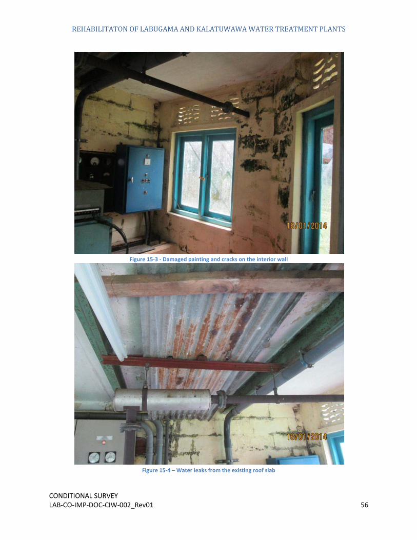
This building is in need of improvements to bring it up to a satisfactory standard. Minor and major cracks are visible all over the interior=r surface of the wall. Building floor has also been damaged while interior and exterior walls need much cleaning to bring it up to the good appearance. Generator and all other mechanical and electrical components working condition is acceptable and currently being used for daily operation.
Concrete roof is leaking water from its cracks and posses treat to the mechanical components inside the building.
Generator Room

REHABILITATON OF LABUGAMA AND KALATUWAWA WATER TREATMENT PLANTS
CONDITIONAL SURVEY LAB-CO-IMP-DOC-CIW-002_Rev01 55
Figure 15-1 - Generator room
Figure 15-2 – Generator
REHABILITATON OF LABUGAMA AND KALATUWAWA WATER TREATMENT PLANTS
CONDITIONAL SURVEY LAB-CO-IMP-DOC-CIW-002_Rev01 56
Figure 15-3 - Damaged painting and cracks on the interior wall
Figure 15-4 – Water leaks from the existing roof slab

REHABILITATON OF LABUGAMA AND KALATUWAWA WATER TREATMENT PLANTS
CONDITIONAL SURVEY LAB-CO-IMP-DOC-CIW-002_Rev01 57
16. Administration
These buildings are in need of improvements to bring them up to a satisfactory standard for its functional operation. Once a general cleaning and painting including the minor crack repairs of the premises is conducted the buildings will be up to its functional standard.
Existing gutter and the down pipe assembly is not in proper functioning due to lack of maintenance, therefore it can be seen that where the system is broken have tend to introduce mosses and algae due to the water leaks from these places.
Storm water drain at the front side of the building need cleaning for it proper functioning, without blocking the system as the current state have visible shrubs and vegetation growing up inside the drain.
Because these buildings are situated adjacent to the roadway, the employees working in these buildings will likely be disturbed by the day to day operation of the project. Therefore it was proposed to build an alternate temporary access way in order to continue the proposed construction activities via this temporary access road.
Building
Figure 16-1 - Admin building front view

REHABILITATON OF LABUGAMA AND KALATUWAWA WATER TREATMENT PLANTS
CONDITIONAL SURVEY LAB-CO-IMP-DOC-CIW-002_Rev01 58
Figure 16-2 - Front drain with vegetation
Figure 16-3 - Admin building inside improper electrical system
REHABILITATON OF LABUGAMA AND KALATUWAWA WATER TREATMENT PLANTS
CONDITIONAL SURVEY LAB-CO-IMP-DOC-CIW-002_Rev01 59
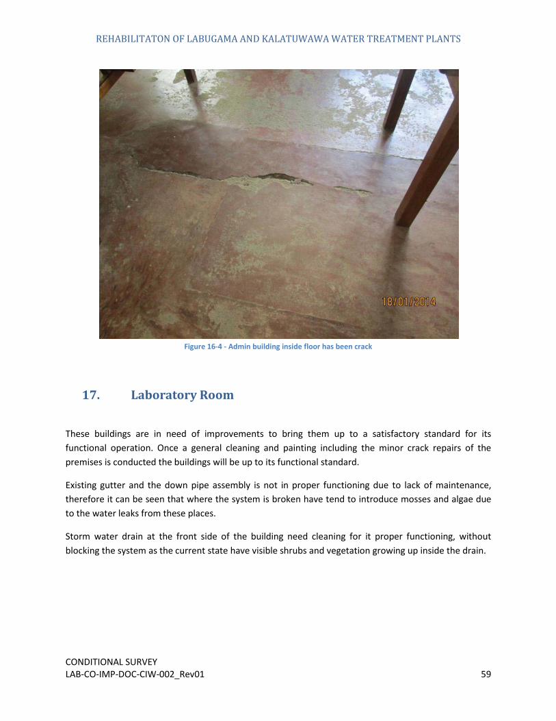
Figure 16-4 - Admin building inside floor has been crack
17. Laboratory
These buildings are in need of improvements to bring them up to a satisfactory standard for its functional operation. Once a general cleaning and painting including the minor crack repairs of the premises is conducted the buildings will be up to its functional standard.
Existing gutter and the down pipe assembly is not in proper functioning due to lack of maintenance, therefore it can be seen that where the system is broken have tend to introduce mosses and algae due to the water leaks from these places.
Storm water drain at the front side of the building need cleaning for it proper functioning, without blocking the system as the current state have visible shrubs and vegetation growing up inside the drain.
Room

REHABILITATON OF LABUGAMA AND KALATUWAWA WATER TREATMENT PLANTS
CONDITIONAL SURVEY LAB-CO-IMP-DOC-CIW-002_Rev01 60
Figure 17-1 - Laboratory room
Figure 17-2 - Loose painting due to moisture effect
REHABILITATON OF LABUGAMA AND KALATUWAWA WATER TREATMENT PLANTS
CONDITIONAL SURVEY LAB-CO-IMP-DOC-CIW-002_Rev01 61
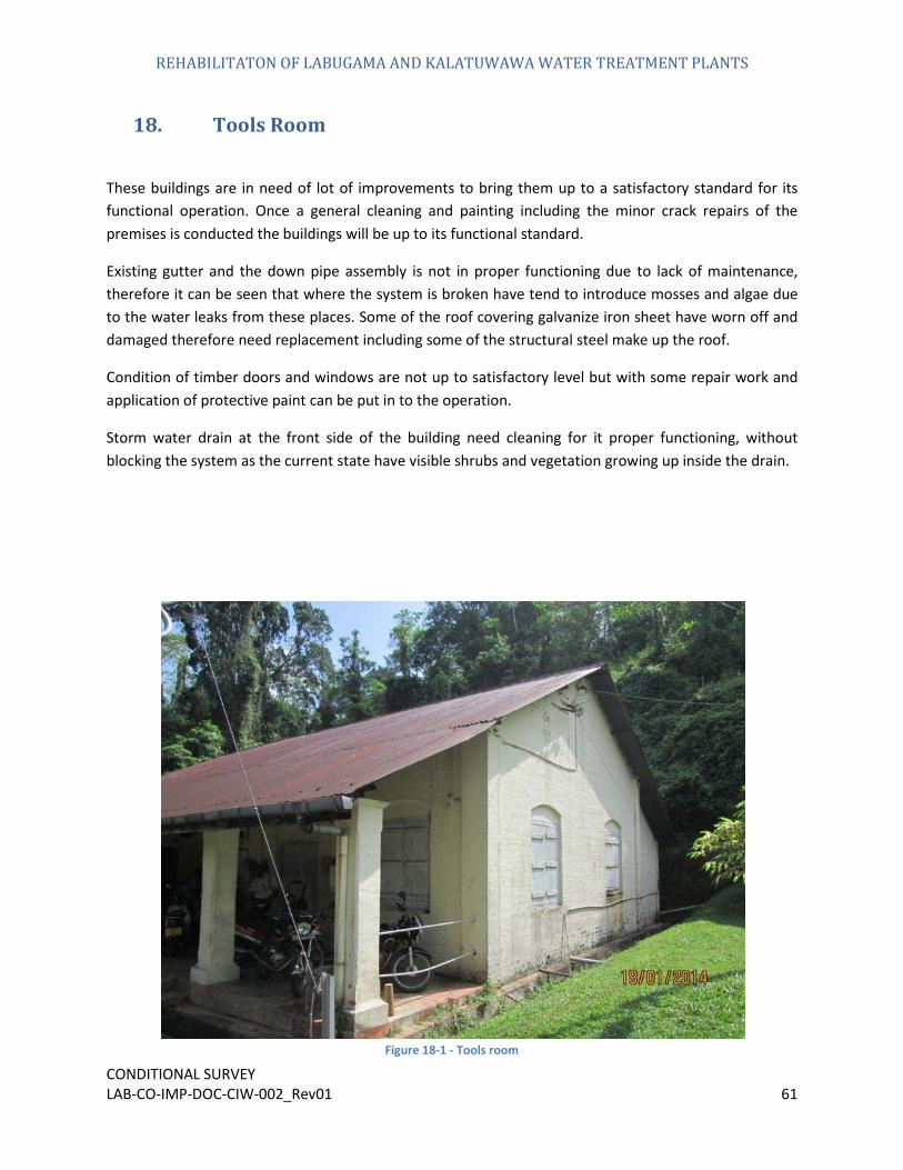
18. Tools
These buildings are in need of lot of improvements to bring them up to a satisfactory standard for its functional operation. Once a general cleaning and painting including the minor crack repairs of the premises is conducted the buildings will be up to its functional standard.
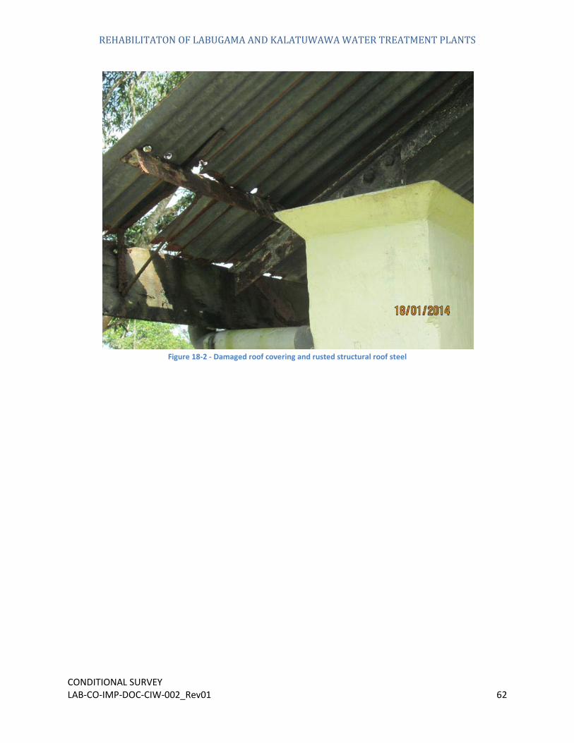
Existing gutter and the down pipe assembly is not in proper functioning due to lack of maintenance, therefore it can be seen that where the system is broken have tend to introduce mosses and algae due to the water leaks from these places. Some of the roof covering galvanize iron sheet have worn off and damaged therefore need replacement including some of the structural steel make up the roof.
Condition of timber doors and windows are not up to satisfactory level but with some repair work and application of protective paint can be put in to the operation.
Storm water drain at the front side of the building need cleaning for it proper functioning, without blocking the system as the current state have visible shrubs and vegetation growing up inside the drain.
Room
Figure 18-1 - Tools room
REHABILITATON OF LABUGAMA AND KALATUWAWA WATER TREATMENT PLANTS
CONDITIONAL SURVEY LAB-CO-IMP-DOC-CIW-002_Rev01 62
Figure 18-2 - Damaged roof covering and rusted structural roof steel
REHABILITATON OF LABUGAMA AND KALATUWAWA WATER TREATMENT PLANTS
CONDITIONAL SURVEY LAB-CO-IMP-DOC-CIW-002_Rev01 63
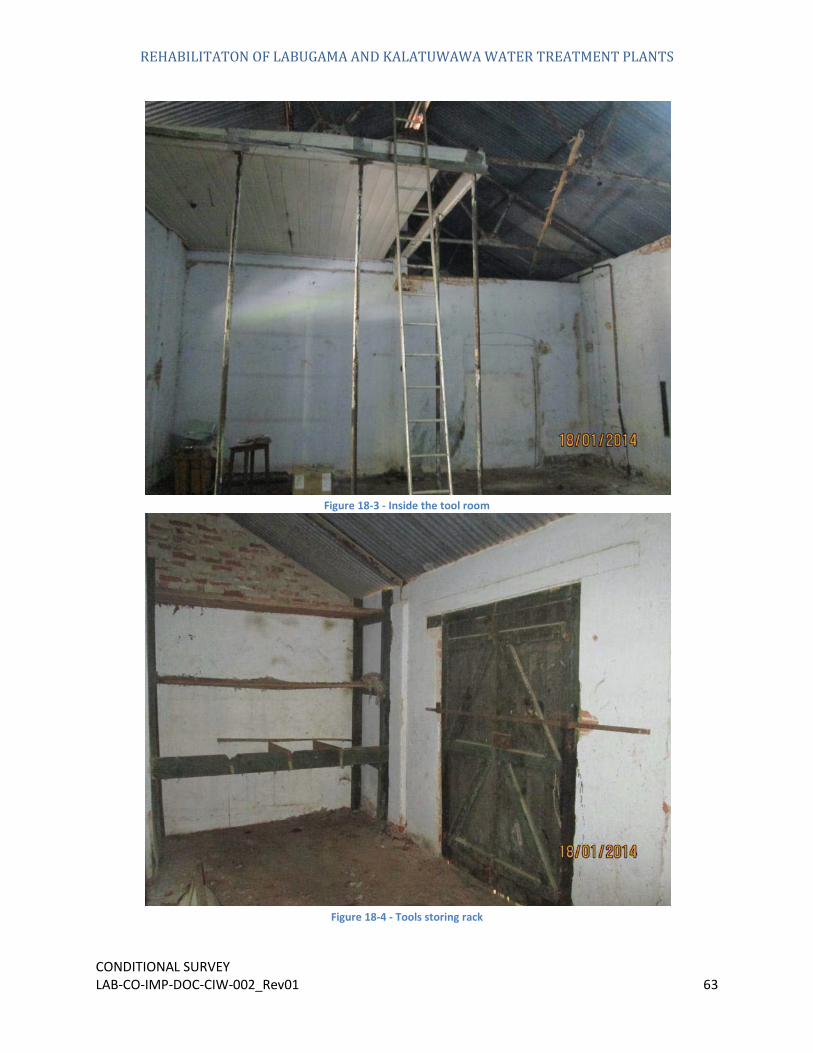
Figure 18-3 - Inside the tool room
Figure 18-4 - Tools storing rack

REHABILITATON OF LABUGAMA AND KALATUWAWA WATER TREATMENT PLANTS
CONDITIONAL SURVEY LAB-CO-IMP-DOC-CIW-002_Rev01 64
19. Workshops
These buildings are in need of improvements to bring them up to a satisfactory standard. The garage structure is inadequate to house all the vehicles that come and go while still exposing them to the elements. The workshop and stores have not been maintained. Dust, dirt and oils can be found on these premises and it is in need of a thorough cleaning.
Roof covering including the trusses have shown up the signs of deterioration but
and Garage
Figure 19-1 - Workshop and Garage

REHABILITATON OF LABUGAMA AND KALATUWAWA WATER TREATMENT PLANTS
CONDITIONAL SURVEY LAB-CO-IMP-DOC-CIW-002_Rev01 65
Figure 19-2 – Workshop building with rusted roof trusses and unserviceable ventilation elements

REHABILITATON OF LABUGAMA AND KALATUWAWA WATER TREATMENT PLANTS
CONDITIONAL SURVEY LAB-CO-IMP-DOC-CIW-002_Rev01 66
Figure 19-3 - Garage showing the damaged plaster with rusted unserviceable roof trusses

REHABILITATON OF LABUGAMA AND KALATUWAWA WATER TREATMENT PLANTS
CONDITIONAL SURVEY LAB-CO-IMP-DOC-CIW-002_Rev01 67
20. Security Officer’s Rest Room
This building is in need of minor improvements to bring them up to a satisfactory standard. The interior of the structure is in good shape only except in need of only minor repairs to the cracks and the damage plaster in the interior wall. There are some cracks that have grown inside building. The structure is also in need of a good paint job while preparing its minor damages that appears in the walls and the roof structure for it to contribute its regular function for several years ahead.
External wall surface is dress up with the basalt rock boulders and state of them call for general cleaning on the wall in order to bring it up to a satisfactory appearance. Some of the mortar bedding in the stone dress up wall appeared to have deteriorated and repair work is call for.
Figure 20-1 - Security officer’s rest room

REHABILITATON OF LABUGAMA AND KALATUWAWA WATER TREATMENT PLANTS
CONDITIONAL SURVEY LAB-CO-IMP-DOC-CIW-002_Rev01 68
Figure 20-2 - Roof structure
Figure 20-3 - Unsafe electrical fitting

REHABILITATON OF LABUGAMA AND KALATUWAWA WATER TREATMENT PLANTS
CONDITIONAL SURVEY LAB-CO-IMP-DOC-CIW-002_Rev01 69
Figure 20-4 - Decayed timber frame

REHABILITATON OF LABUGAMA AND KALATUWAWA WATER TREATMENT PLANTS
CONDITIONAL SURVEY LAB-CO-IMP-DOC-CIW-002_Rev01 70
Figure 20-5 - Damaged plaster in the wall
21. Officer’s Rest Room 01
The building is currently housed by the Sri Lanka Army personal as their quarters and the status of the building is as follows.
This building is in need of some minor improvements to bring them up to a satisfactory standard. As shown in following figures the functional components within premise is not at its fully order.
Some part of the Wooden door and window in the building have deteriorated to a great extent, need repair work including final paint coat to protect it from the adverse weather conditions.
In addition to repainting and cleaning the structure further measures such as crack repairing and renovation of roof structure must be undertaken to restore the building into an acceptable standard. Furthermore the existing toilet condition is not at its hygienic level therefore it required a refurbishment for its proposed functionally.
In addition to the above the existing electrical system is not up to the satisfactory level and clustered wire can be seen in the building which poses threat to the people living in the building.

REHABILITATON OF LABUGAMA AND KALATUWAWA WATER TREATMENT PLANTS
CONDITIONAL SURVEY LAB-CO-IMP-DOC-CIW-002_Rev01 71
Figure 21-1 - Officer building inside
Figure 21-2 - Officer's rest room toilet
REHABILITATON OF LABUGAMA AND KALATUWAWA WATER TREATMENT PLANTS
CONDITIONAL SURVEY LAB-CO-IMP-DOC-CIW-002_Rev01 72
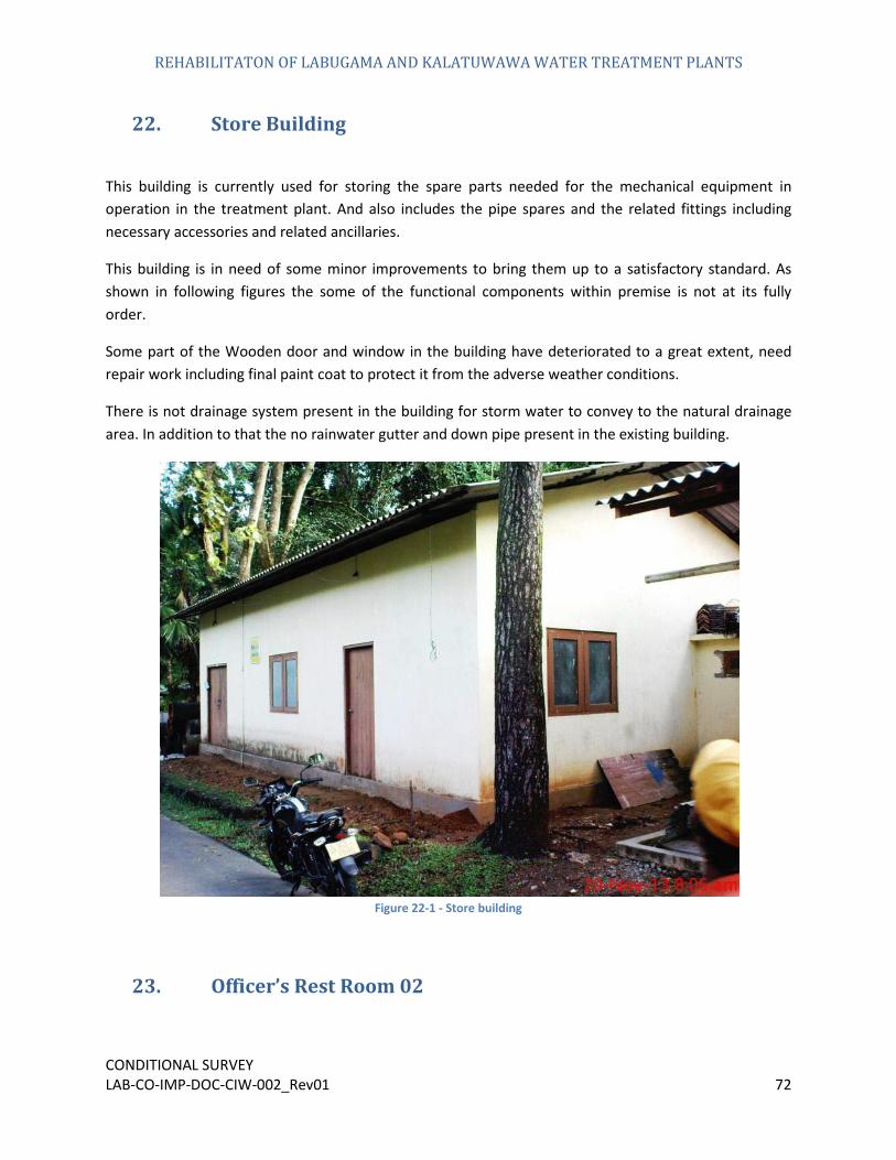
22. Store Building
This building is currently used for storing the spare parts needed for the mechanical equipment in operation in the treatment plant. And also includes the pipe spares and the related fittings including necessary accessories and related ancillaries.
This building is in need of some minor improvements to bring them up to a satisfactory standard. As shown in following figures the some of the functional components within premise is not at its fully order.
Some part of the Wooden door and window in the building have deteriorated to a great extent, need repair work including final paint coat to protect it from the adverse weather conditions.
There is not drainage system present in the building for storm water to convey to the natural drainage area. In addition to that the no rainwater gutter and down pipe present in the existing building.
Figure 22-1 - Store building
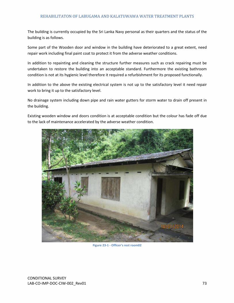
23. Officer’s Rest Room 02
REHABILITATON OF LABUGAMA AND KALATUWAWA WATER TREATMENT PLANTS
CONDITIONAL SURVEY LAB-CO-IMP-DOC-CIW-002_Rev01 73
The building is currently occupied by the Sri Lanka Navy personal as their quarters and the status of the building is as follows.
Some part of the Wooden door and window in the building have deteriorated to a great extent, need repair work including final paint coat to protect it from the adverse weather conditions.
In addition to repainting and cleaning the structure further measures such as crack repairing must be undertaken to restore the building into an acceptable standard. Furthermore the existing bathroom condition is not at its hygienic level therefore it required a refurbishment for its proposed functionally.
In addition to the above the existing electrical system is not up to the satisfactory level it need repair work to bring it up to the satisfactory level.
No drainage system including down pipe and rain water gutters for storm water to drain off present in the building.
Existing wooden window and doors condition is at acceptable condition but the colour has fade off due to the lack of maintenance accelerated by the adverse weather condition.
Figure 23-1 - Officer's rest room02
REHABILITATON OF LABUGAMA AND KALATUWAWA WATER TREATMENT PLANTS
CONDITIONAL SURVEY LAB-CO-IMP-DOC-CIW-002_Rev01 74
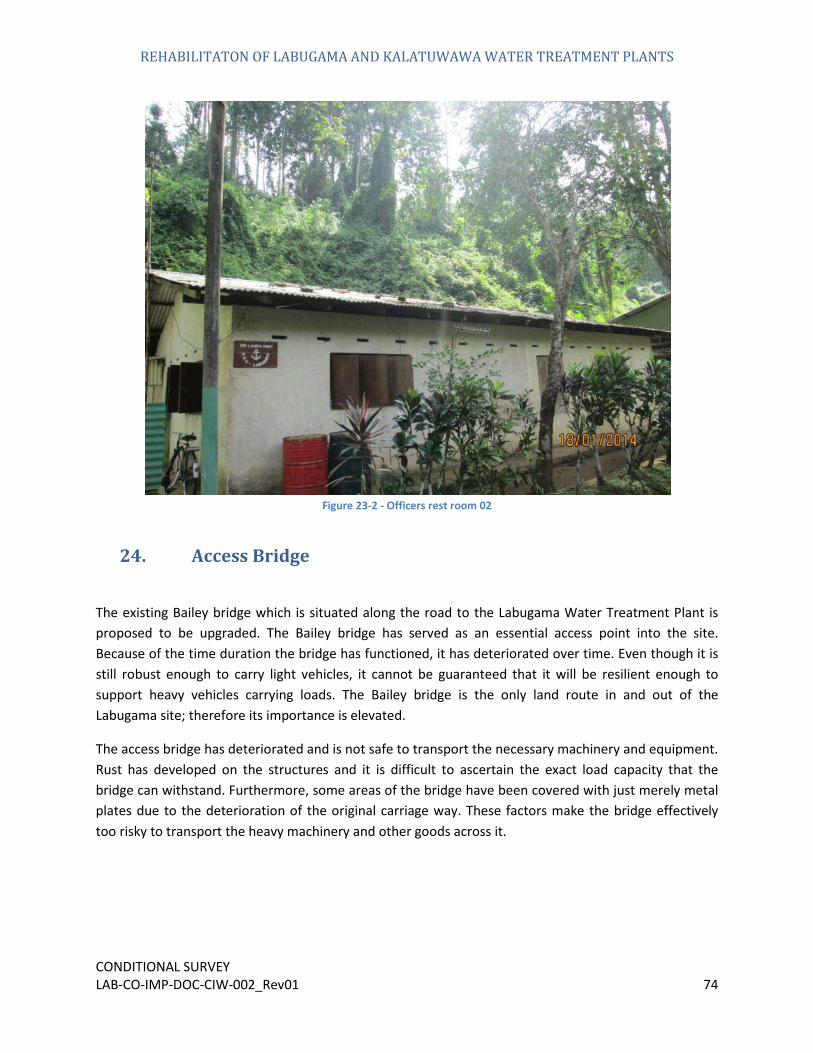
Figure 23-2 - Officers rest room 02
24. Access Bridge
The existing Bailey bridge which is situated along the road to the Labugama Water Treatment Plant is proposed to be upgraded. The Bailey bridge has served as an essential access point into the site. Because of the time duration the bridge has functioned, it has deteriorated over time. Even though it is still robust enough to carry light vehicles, it cannot be guaranteed that it will be resilient enough to support heavy vehicles carrying loads. The Bailey bridge is the only land route in and out of the Labugama site; therefore its importance is elevated.
The access bridge has deteriorated and is not safe to transport the necessary machinery and equipment. Rust has developed on the structures and it is difficult to ascertain the exact load capacity that the bridge can withstand. Furthermore, some areas of the bridge have been covered with just merely metal plates due to the deterioration of the original carriage way. These factors make the bridge effectively too risky to transport the heavy machinery and other goods across it.

REHABILITATON OF LABUGAMA AND KALATUWAWA WATER TREATMENT PLANTS
CONDITIONAL SURVEY LAB-CO-IMP-DOC-CIW-002_Rev01 75
Figure 24-1 -Bailey bridge
Figure 24-2 - Structural truss beam

REHABILITATON OF LABUGAMA AND KALATUWAWA WATER TREATMENT PLANTS
CONDITIONAL SURVEY LAB-CO-IMP-DOC-CIW-002_Rev01 76
Figure 24-3 - Deteriorated steel trusses
25. General Premises
No proper drainage system is present to collect the storm water from the roof tops.
Generally the conditions of the Guard rails running along the road are ok but show some deteriorated sings in some section that need repair work to stop further deterioration of these units.
Some of the existing natural slops pose threat to the commuters roaming in the treatment plant road network as this unit can be prone to landslides/mud flow as the ground water table rises.
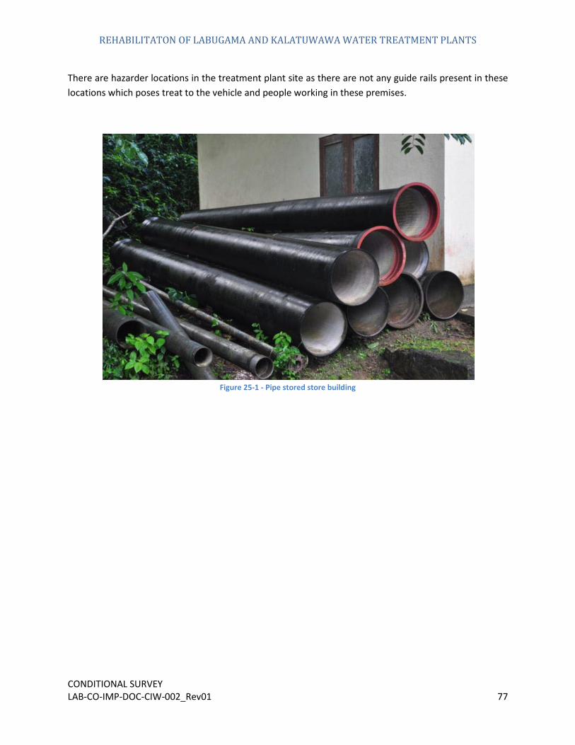
The entire area is littered with pipes and other items as shown in following figures Owing to this reason; there is a possibility of deteriorating these materials stored in such a manner.
Existing fuel storage tank is in good functional condition. Even though it is in working condition is acceptable, it had aged with time and lost its lustre.
Existing road condition is generally in good condition since the present road has been constructed in recent past. But small defect can be found in some location as the construction work has not been subjected to a good quality control procedure.
REHABILITATON OF LABUGAMA AND KALATUWAWA WATER TREATMENT PLANTS
CONDITIONAL SURVEY LAB-CO-IMP-DOC-CIW-002_Rev01 77
There are hazarder locations in the treatment plant site as there are not any guide rails present in these locations which poses treat to the vehicle and people working in these premises.
Figure 25-1 - Pipe stored store building

REHABILITATON OF LABUGAMA AND KALATUWAWA WATER TREATMENT PLANTS
CONDITIONAL SURVEY LAB-CO-IMP-DOC-CIW-002_Rev01 78
Figure 25-2 - Places where the handrail is utmost impotence
Figure 25-3 - Defects in the road network

REHABILITATON OF LABUGAMA AND KALATUWAWA WATER TREATMENT PLANTS
CONDITIONAL SURVEY LAB-CO-IMP-DOC-CIW-002_Rev01 79
Figure 25-4 - Hazarders slope
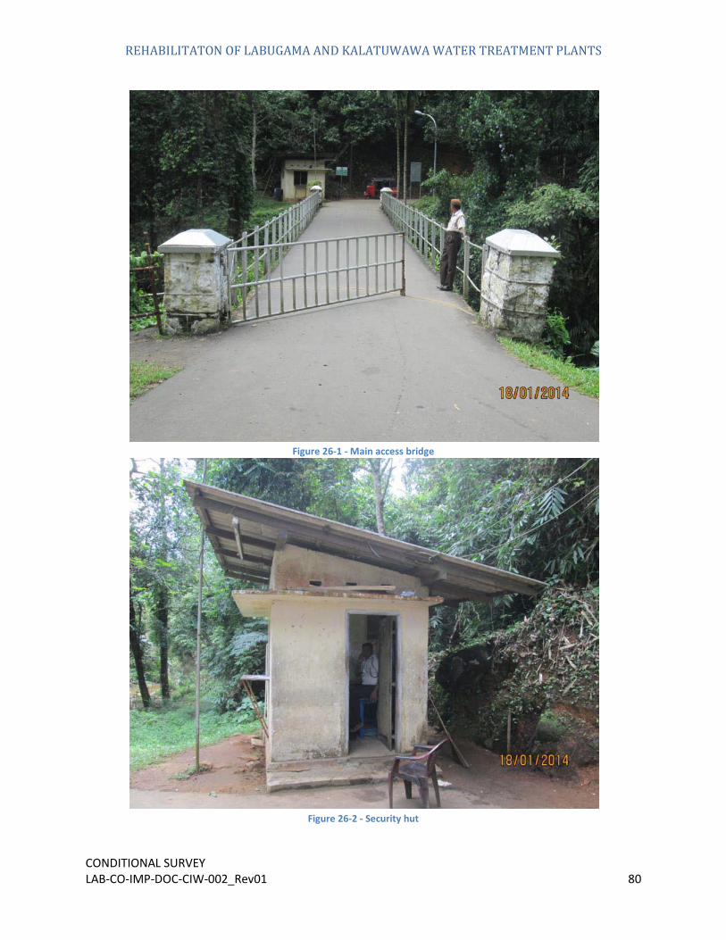
26. Main Entrance
Main entrance to the site is generally found in good condition except some parts need some adjustment.
Stone columns on the four corners of the main access bridge are out of the alignment and need adjustment for its good appearance.
Security hut near the main access bridge condition is acceptable and with minor repair work and painting coat can be put in to operation without need of much effort.
Main entrance gate is in working condition but the operation task need much effort , as the rolling wheel mechanism cause trouble when it operate.
REHABILITATON OF LABUGAMA AND KALATUWAWA WATER TREATMENT PLANTS
CONDITIONAL SURVEY LAB-CO-IMP-DOC-CIW-002_Rev01 80
Figure 26-1 - Main access bridge
Figure 26-2 - Security hut