Embed Size (px)
Citation preview

This is a preprint or reprint of a paper intended for presentation at a conference. Because changes may be made before formal publication , this is made available with the understanding that it will not be cited or reproduced without the permission of the author.
CONDITION MONITORING OF HELICOPTER GEARBOXES BY EMBEDDED SENSI NG1
Abhijit Suryavanashi , Graduate Research Assistant
Shengda Wang, Graduate Research Assistant Robert Gao, Associate Professor
Kourosh Danai, Professor2
Department of Mechanical and Industrial Engineering University of Massachusetts Amherst , Massachuset ts
David G. Lewicki Vehicl Technology Dir ctorate
U.S. Army Research Laboratory
NASA Glenn Research Center
Cleveland, OH
ABSTRAC T
Health of helicopter gearboxes is commonly assessed by monitoring the housing vibration, thus it is challenged by poor signal-to-noise ratio of the signal measured away from t he source. It is hypothesized that vibration measurements from sensors placed inside the gearbox will be much clearer indicators of faults and will eliminate many of the difficul t ies faced by present condit ion monitoring systems. This paper out lines our approach to devising such a monitoring system. Several tasks have been outlined toward this objective and the strategy to address each has been described. Among the tasks are wireless sensor design, antenna design, and selection of sensor locations.
I N TRODUCTION
Present helicopter power t rain are significant contributors to both flight safety incidents and maintenance costs . Rapid and reliable detection and diagnosis (isolation) of faults in helicopter gearboxes is t herefore necessary to prevent major breakdowns due to progression of undetected faults, and for enhancing personnel afety by preventing catastrophic failures. Fault detection and diagnosis is also nec ssary for red ucing maintenance costs by eliminating the need for routine disassembly of the gearbox, and for saving time during inspection.
Detection and diagnosis of helicopter gearbox faults, like most rot ating machinery, is based upon oil analy-
, Presented at t he Ameri can Helicopter Society 58th Annual Forum. Montrea l Canada. J une 11-13. 2002. Copyrig ht e by the American He li copter Society Internationa l. Inc. All rights reserved.
2To whom all correspondence shou ld be addressed Emai l: danai @ecs.umass.edu
~ ___ --L-.... _ ___ _ ~
1
sis and vibration monitoring. Oil analysis is used to detect the presence of metallic debris by: (1) magnetic plugs (chip detectors), (2) oil filters , or (3) Spectrometric Oil Analysis (SOA) [1 , 2] . Vibration monitoring is performed to detect abnormal vibration resulted from faults, with the analogy t hat under normal operating conditions, each component in the gearbox produces vibra tions at specific frequencies which are related to t he component's rotational frequency. In case of a component fault , the vibration genera ted by the faulty component will be different from the normal vibration , reflected at the component 's rotational frequency and its harmonics. In order to be nonint rusive, vibration is measured by accelerometers mounted on the housing. But this leads to difficulty in detecting vibration changes ca used by component faults, due to the attenuation of vibration by the housing and t he relatively long vibration travel path between the component fault and the externally mounted accelerometers.
In order to enhance identification of changes in vibra-
https://ntrs.nasa.gov/search.jsp?R=20020070865 2018-06-05T03:30:42+00:00Z

t ion due to component faul ts, vibration analysis i performed at two levels: (1) feature extraction, and (2) data integration (fusion). At t he feature extraction level, the raw vi bra tion is proces ed to yield ' features' associated wit h the frequencies related to the gearbox components . Accordingly, considerable effort has been directed toward ident ification of individual feat ures that would consistent ly reflect specific gearbox faults [3, 4, 5]. At t he integration level, the mult it ude of features obtained from several accelerometers are studied together to detect the presence of an abnormality and its source. In the t raditional approach to data integration, a human diagnostician first identifies abnormalities in vibration features . He/she then relates these features to component faults based on the proximity of the acceleromet r producing those feat ures as well as the type of component fault charac-erized by he feature . Using this informat ion, t he di
agnostician hypoth sizes faul ts in specific components and then verifies or discards t he hypothes is by examining features from other accelerometers in the proximity of the suspect component . In order to facilitate the integration of vibration at this level, pat tern classifiers in the form of neural networks have been proposed [6, 7, 8, 9] to take advantage of their nonlinear pattern classification capabi li ty, improved robustnes to noise, and computational effi ciency. Despite significant progress in feature extraction a nd data fusion, monitoring systems are hampered by the inherent poor signal- to- noise (S/ N) rat io of the vibra tion measured on the housing.
The objective of this research is to explore the utility of embedded sensors in condit ion monitoring, to take advantage of the improved clari ty attained from t heir close proximity to the sow'ce of signal generation. The recent advances in sensor miniaturization technology, as wi tnessed by the rapid development of MEMS (Micro-Electro-Mechanical Systems) [10], has led to development of advanced miniaturized sensors t ha t have been increasingly applied to on-line condition monitoring of mechanical systems and processes [11 , 12]. Compar d to t heir convent ional counterparts, t he small dimension and light weight of these new sensors make it possible to place them close to the source, without causing appreciable disturbance in the dynamics of the host system. It has been shown in prior research [13] that the physical proximity of the sensors to the component faults will result in higher signa l-to-noise ratios, and will naturally lead to improved signal acquisit ion and feature ext raction.
The feasibility of embedded sensing for gearbox health monitoring is evaluated in applicat ion t o an OH-58A
2
helicopter gearbox (Fig. 1). The use of embedded wireless sensors int roduces new concerns in regard to sensor placement and feature extraction. The designer now has access to a mult it ude of potent ia l sensor locations within the gearbox t hat were previously unavailable. Moreover, some of these locations will be on rotating components with vari able t ravel paths to individual faults . As t he basis of methodical sensor locat ion selection, a connectionist network model of t he gearbox structure is proposed to represent t he travel paths between potent ial sensor locations and component faults . The parameters of this network will be initialized according t o a fini te element model of the g arbox and then cali brated by structural modal experiments . The information derived from these travel paths will then be used to define an effect ive sui te of sensor locations according to their accelerometer coverage (i.e., the numb r of componen s each location covers), and the level of redundancy between various locations [14]. Embedded sensing of gear boxes also creates new challenges such ~ space constraints , signal transmission difficulties , effect of rotation on the measured vibration and feature extract ion, and harsh operating condit ions inside the gearbox. St rategies for addressing some of these issue are also discussed in this paper.
Planet
Sun Gear(SG)
Mast RoHer Bearing(MRB)
Mast Ball Bearing(MBB)
Spiral Bevel G.ar(SBG)
Pinion Roller Bearing(PRB)
Spiral Bevel Pinion(SBP)
Triplex Bearing(TB)
Figure 1: Layout of the various components in the OH-58A helicopter gearbox .
WIRELESS SENSING
Vibrat ion signals measured by an embedded sensor can be transmitted wirelessly by optical and electromagnetic means. Optical means based on infrared or laser
~.----~----. -----~---

\ , '
r quires line-of-sight for data t ransmission and reception, which is generally not available due to blockage by contamination andlor machine structure. On the other hand, electromagnetic-based radio frequency (RF) air-link is not restricted by the line-of-sight constraint , but is constrained by t he shielding effect of t he metallic housing. This constraint can be bypassed by inclusion of a non-metallic window on t he housing and incorporation of a more elaborate antenna design.
R equirem ents and Const raints
Th embedded sensing module will contain a sensing element , a signal processing circui t (charge amplifier), and a wireless transmi tter. The RF wireless comm unication design will be subject to several spatial and physical constraints :
1. The wireless transmitter, together wit h the sensing el ment and measurement electronics such as t he signal condit ioning circuit, will be constrained to small slots, typically on the order of 18 mm x 34 mm x 4 mm [15]. The slot for the sensing mod ule will need to be cut within each component.
2. Bandwidt h of at least 10 kHz will be required to cover t he spectrum of vibration typically generated in the gearbox [16].
3. The antenna length is limited to t he restricted space inside and around the slot cut in the component . The electromagnetic shielding effect of t he surrounding metallic structure will also need to be considered. High noise immunity is required to reduce the influence of possible environmental electro-magnetic interference on t he signal. This is part icularly important for early detection of faults when the fault-generated vibration is weak during the earlier stages of faults .
A circuit design t hat satisfi es the space constraint will need to use t he least number of components for the sensing module. The bandwidt h specification also affects the design for wireless data transmission. Moreover, to achieve the best RF transmission ffi ciency, the antenna mu t be longer than one quarter of the carrier's wavelength 1 [17]. A carrier of higher frequency (1) has a shorter wavelength according to the relationship f,). = c (where c denotes the speed of light 3 x 10⁸ m/s) , but requires more power. For this study, the frequency of 916 MHz is chosen, which is located within the license-free 902-928 MHz industrial, science and medical application (ISM) band, provided t hat
3
the maximum transmitting power is I ss than 1 W [18] . The shortest antenna length required for optimal signal radiation is calculated to be 8 em (,)./4) . To enable signal transmission, the physical size of the nonmetallic housing window needs to satisfy t he ')'14 requirement.
D ifferent Modulation Schem es
Different modulation schemes can be used for t ransmitting analog signals . Frequency modulation (FM), amplit ude modulation (AM), and digital pulse coded modulation (PCM) have been widely used in telemetry [17]. Among the three mod ula tion schemes, AM modu lat ion i less often u ed when accuracy is important, whereas PCM and FM account for about 85% of telemetry applicat ions because of their good signal t ransmission quali ty [17]. Other modulation schemes are generally too complicated for miniaturization of sensing components within a gearbox.
The SIN ratio is an important consideration when select ing a modulation scheme for wireless t ransmission . For a signal transmission channel wit h white Gaussian noise, the SI N ratios of FM and AM modulation are defi ned , respectively, as [19]:
2 Pm Pr SNRFM = 3(3 maxm2(t) X NoW
Pr SNRAM =n-
NoW
(1)
(2)
where PT denotes the power of the total signal t ransmitted , Pm represents t he power of the message signal m (t ), n(::; 1) denotes the ra tio of Pm to Pr , No represents t he power spectra l density of white Gaussian noise, W denotes the bandwidt h of the message signal m (t ), and (3 represents t he FM modulation index.
In the above quations, the message signal met ) is the input to t he t ransmit ter , and t he term ma:;;lz (t) is no greater than 1 since it is the power of t he normalized message signal ( ma;;"I~(t) I) ' The FM modulation index (3 is defined as t he ratio of t he frequency deviation to the highest frequency in the message signal. To reduce the signal distortion in FM, (3 is often selected such t hat (3 2: 5 and 3{32 ma:;;lz(t) is much greater than 1 for high SIN ratio. H nee, t he SIN rat io of FM is about 3{32 times higher than t hat of AM.
The draw back of using FM is that a wider channel bandwidth is required t han in AM. For t he gearbox vibration wit h a bandwidt h of about 10 kHz, the corresponding bandwidth for AM signal transmission will

be BWAM = 2fm = 20kHz. The bandwidth needed for FM with {3 = 5 will be 120 kHz according to Carson's Rule [20]:
(3)
which is 6 tim s wider than required for the AM t ransmission bandwidth. The bandwidths needed for other digital modulation techniques, such as PCM, depend on t he sampling frequency, AID conversion resolution, and the digital transmitt r. For a sampling frequency f s , -bi t AID conversion, and amplit ude shift keying (ASK) modulation, the bandwidth for PCM will be BWPCM = 2fsN. For example, for f s = 100 kHz and N = 12 bits, the BWPCM will be 2400 kHz, which is 20 t imes wider than that of FM, and 120 times t hat of AM. Wide bandwidths not only make the implementation of miniaturization more difficult , t hey will reduce channel capacity. Since noise immunity is the most critical requirement for gearbox condit ion monitoring, t he PCM data transmiss ion scheme is selected for its good SIN ratio transmission, but its circuit ry is simplified using a voltage-to- frequency (VFC) scheme.
'Transmitter D esign
The schematic of the d signed PCM t ransmitter is shown in Fig. 2. It includes an AID conver ter, a parallel- to-serial conver ter , and a RS232 encoder for data packaging and synchronization t hat may require coordination by a microprocessor. The advantage of PCM is t hat in conj unction wit h AID converter the data format of receiver out put is ready for a microprocessor or a computer, and digitization error can be neglected.
F igu re 2: Schematic view of the data transmit ter .
In min iaturization of t he sensing module, in addit ion to the single chip design to satisfy t he size requirement, t he input and output signal dynamic range , single power supply, power consumption, and IC die availabili ty need to be considered for t he VFC design. A
4
monolithic digital ASK t ransmitter TX6000 [21] is selected to t ransmit t he frequency modulated (FM) signal from VFC. Hence, the VFC frequency outp ut has to match t he input throughput capacity of TX6000, i.e., a nominal data rate of 115.2 kbps . For a square wave, the high and low voltage levels represent di fferent binary bits, and since one single-cycle square wave represents two bits of data, t he 115.2 kbps data rate sets the upper frequency limi t of t he square wave from the VFC to 57.6 kHz. This is implemented by a VFC chip LM331 that out puts square waves of 56. 5 kHz. Under the cont rol of the condi t ioning circuit output , t he VFC output contains the frequency range of 26.4 kHz to 55.4 kHz and has a non-lineari ty of about 0.13%. It can be shown that using t he VFC design with an output frequency range 26 .4 - 55 .4 kHz and the TX6000 transmitter , a bearing signal with t he maximum frequency of up to 2 kHz can be t ransmitted with 98% of the signal energy retained , result ing in a signal distortion ratio of 2% [20]. The physical size of t he developed circui t can be reduced by using the surface mount (SMT) and hybrid techniques, as shown in Fig. 3.
F igure 3: Prototype of the RF transmitter using hyb r id t echniques.
T he signal sensing and t ransmission capabili ty of the design d wireless sensor module, incorporating the RF t ransmitter and a piezoceramic sensing element, was compared with that of a standard Kistler accelerometer (model # 8692B50). The wireless sensor was mounted in a back-to-back arrangement on the Kistler sensor, which was mounted on the ring gear of the planetary subsystem of the OH-5 A helicopter gearbox. The top case was t hen replaced and bolted down. The wired connection for the Kistler sensor was routed
---------- ------'

I .
through an opening in the top case which is reserved for the output shaft of the gearbox. The same opening a lso allowed the signal to be t ransmitted wirelessly outside the gearbox. In t he final design , it is envisioned that an opening in the casing sealed by a plastic cap (similar to an oil level indicator) will serve as the pathway for the wireless signaL An impulse was introduced onto the outer casing by an impact hammer and signals from both sensors were recorded. The power spectral density (PSD) plots of the signals measured by th two sensors, along with their corr lation, are shown in Fig. 4. The results indicate that the crosscorrelation between the Kistler sensor signal and the wireless signa l have a maximum value a t zero phase lag. The variation around t he maximum value is due to the noise present in the two signals. The characteristic high correlation coeffi cient at zero phase lag and t he sharp drop for ev n small phase differences indicate that the wireless sensor functions as t he commercial sensor.
SENSOR LOCATION SELECTION
Sensor placement is an important considerat ion in embedded sensing, since a balance needs to be provided between the number of sensors used and the coverage of the possible faults wit hin the various components . To illustrate this concept, one may consider the coverage of faul ts on the ring gear , t he planet gear , and the sun gear by a sensor mounted on a planet of the OH-58A gearbox (Fig. 5). The t ransmission of vibration to the sensor from the t hree faults varies as the gears mesh with one another at the fault locations. For Fault 1, there will be two sources of excitation: one when the planet meshes with the ring gear and the other when the planet meshes with the sun gear . For both sources, however, the travel paths are approximately t he same. For Fault 2, where the fault is on a planet gear different from t he one with the sensor , t here will be the same two sources of excitat ion, but the t ravel paths will differ - one path includes the ring gear while the other includes the sun gear . For Fault 3, the vibration measured by the sensor will be the weakest when the other planets come into contact with the ring gear at the fault location, unti l the sensor-mounted planet itself meshes the ring gear at the fa ul t location.
As illustrated in the above example, sensor placement needs to be performed by considering the travel paths between various faul ts and the candidate locations. Methodical specification of such travel paths may be
5
Kistler 2e-6 PSD Kistler sensor sensor
Q)
~ Ilj!L J "'0
.~ Ci E
<i
-, Time , ,
0,0 500 Freq 1k 1.5k
1-w ireless 2e-6
PSD wireless sensor sensor
Q) "'0
.~
JlJ 0.
~~. E
<i
-, - . Time , , , ,
0,0 500 Freq 1k 1.5k
86.6-cross
correlation Q)
plot "'0
.~ 0. E
<i
0.0-, o Phase
Figure 4: Frequency spectra l density of t he signals measured by the two sensors and their corre lation .
Fault 3
Fault 2
Figure 5: A possible sensor placement scenario
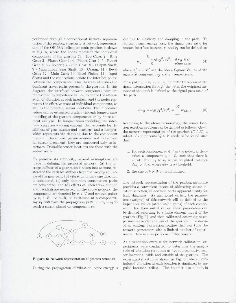
performed t hrough a connectionist network representation of the gearbox structure. A network representation of the OH-58A helicopter main gearbox is shown in Fig. 6, where the nodes repre ent the indiv idual components of the gearbox (1 - Top Case; 2 - Ring Gear; 3 - Planet Gear 1; 4 - Pla net Gear 2; 5 - Planet Gear 3; 6 - Spider; 7 - Sun Gear; 8 - Out put Shaft; 9 - Main Input Gear Shaft; 10 - Casing; 11 - Bevel Gear ; 12 - Main Case; 13- Bevel Pinion; 14 - Input Shaft) and the connections denote the interface points between the components. This diagram identifies the dominant travel paths present in the gearbox. In this diagram, t he interfaces between component pairs are represented by impedance valu s, to define the attenuation of vibra tion at each interface, and the nodes r present the effective mass of individual components, as well as t he potent ial sensor locations. The impedance values can be estimated crudely t hrough lumped mass modeling of the gearbox components or by fini te element analysis. In lumped mass modeling, the interface comprises a spring element , t hat accounts for the stiffness of gear meshes and bearings, and a damper, which represents t he damping due to the component material. Since bearings are assumed not to be used for sensor placement , they are considered only as interfaces . D irable sensor locations are those with the widest reach.
To preserve its simplicity, several assumptions are made in defining the proposed network: (a) the average st iffness of a gear mesh is taken into account, instead of the variable stiffness from t he varying roll angle of the gear pair , (b) vibration in only one direct ion is considered , (c) only dominant transmission paths are con idered, and (d) effects of lubricat ion, fr iction and backlash are neglected . In the above network , the components are denoted by V i E V and contact points by ej E E. As such, an excitation at a component , say v" will have t he propagat ion path V , - V 2 - V 3 to reach a sensor placed on component V 3.
lost due to elasticity and damping in the path. To represent such energy loss, the signal pass ra tio for contact interface between V i and Vj can be defined as
if eij E E othe7'w ise
(4)
where 'if;} and 'if; r are the Mean Square Values of the signals a t component Vj and Vi , respectively.
For a path V i - V i +' , ... , Vj , in order t o repres nt the signal attenuation through the path , the weighted distance of the path is defined as the signal pass ratio of the path:
j)(1
dWij = Log ('if;/ Ni2) = w k,k + ' (5) k=i
According to the above terminology, the sensor location selection problem can be defined as follows . Given the network representat ion of the gearbox G(V, E ), a subset of components Va E V needs to be found uch tha t:
1. For each component Vi E V in the network , there exists a component Vj E Va such that t here is a path from Vi to Vj whose weighted distance dWij > dw o, where dw o is a threshold .
2. the size of V 0, IV 01, is minimized .
The network representation of the gearbox structure provides a convenient means of addressing sensor location selection, in addit ion to its apparent ut ility for fault diagnosis. As mentioned earlier , the parameters (weights) of this network will be defined as the impedance values (attenuation gains) of each component . For their initial values, these parameters can be defined according to a finite element model of the gearbox (Fig. 7), and then calibrated according to experimental modal analysis of the gearbox. The devise of an efficient calibrat ion routine that can tune t he network parameters with a limited number of experimenta l data is a major focus of this research.
As a validation exercise for network calibration, experiments were conducted to determine the magnitude of vibration responses a t five representative sensor locations inside and outside of the gearbox. The
Figure 6: Network representation of gearbox structure . experimental setup is shown in Fig. 8, where faultinduced vibration at each location is simulated by im-
During the propagation of vibration , some energy is pulse hammer strikes. The hammer has a buil t- in
6

· ,.
F igure 7 : Finite element model of the OH-58A Gearbox.
acceleration sensor that captures the impulse. Five Kistler accelerometers (model # 8630A5, # 8636B50 and # 8692B50) were used to measure vibration intensity at the five locations. A sample of sens it ivity values obtained from the experiments are shown in Table I , indicating the individual responses of sensors to force impulses applied at potential fault locations. The sensitivity values were computed as the ratio of the rms values W of the signals, as
1)( wtensor (k) SMi!J' = -6 k wrxcitatiOn(k)
(6)
where k denotes t he number of sample data signals taken for each fault-sensor combination (k = 6, in this case) i =1 al
, "' , 'g' represents t he fault location, and j = SI , ' .. ,S5 denotes the sensor location . The sensor locations, as indicated in Fig. 8, were: S1: Planet Shaft (PI is the planet on which SI was mounted), S2: Spider, S3: Main Input Gear Shaft, S4: P lanetary Ring Gear, and S5 : Main Input Pinion Adapter. The fault locations were: (a) fault on Ring Gear (Ring Gear-PI mesh), (b) fau lt on PI (Ring Gear-PI mesh), (c) fault on P2 (Ring Gear-P2 mesh), (d) faul t on Sun Gear (Sun Gear-PI mesh), (e) fault on P I (Sun GearPI mesh), (f) fault on Input Bevel Gear (Input GearPinion mesh), and (g) fault on Input Pinion (Input Gear-Pinion mesh). For each fault location, t he values were then normalized with respect to the maximum coefficient in ach row. The sensitivity values such as the ones presented in Table I will be the basis for calibrating the network model of the gearbox.
7
Figure 8: Experimenta l setup for the se nsor pl acement sensitivity.
Ta ble 1: Experimenta lly obta ined sensitivity va lues between the sensor and fault locations.
Excitaion Sensor Location Location Sl S2 S3 S4 S5
a 0.014 0.015 0.055 1.000 0.222 b 1.000 0.533 0.124 0.205 0.132 c 0.621 1.000 0.158 0.125 0.125 d 0.367 1.000 0.281 0.290 0.711 e 1.000 0.497 0.148 0.208 0.134 f 0.007 0.012 1.000 0 .039 0.029
9 0.022 0.015 0.074 0.210 1.000
F U T U R E WORK
Fut ure work in this research will focus on a ll aspects of the topics discussed a bove. Specifically, it wi ll include:
1. The Network Model. As mentioned earlier , the parameters of the network mod I will need to be defined and then calibrated according to experimental data. The strategy for cali brating t he network will incorporate th oretical, experimental, and fini te element analysis. The network will be init ialized by simulated vibration from a finite element model of the gearbox, and then refined according to experimental interface-activated energy transfer to various sensor locations. The fine-tuned network will th n be used as the basis for sensor selection and fault diagnosis. It should be noted that t he current network represents vi-

bration transfer in only one direction. As such, three parameter values will n ed to be defined for each connection or node to cover energy t ransfer in x, y and z directions.
2. Sensor Location Selection. The network model will provide a systematic means of defining the attenuation of vibration between component interfaces and potent ial sensor locations. A sen. or locat ion selection strategy will be formulated next to use the information from the network to estimate the coverage and overlap of each location as the basis for sensor location selection.
3. Sensor Design. The sensor used for the current feasibility study has a limited bandwidth sui table for bearing fault detection. For gearbox fault detection, a sensor with a bandwidth of 20 kHz will be de igned. Since thi en or will be exposed to a harsh environment and inertial forces typical of rota ting components, issues related to sensor packaging and t esting will need to be addressed as well. Wit h t he best sensor locations identified , experiments will be conducted to determine the best ways to access t he signal wirelessly outside the gearbox with minimum modificat ions to the existing housing. This will also involve addressing antenna design issue wit hin a maximally shielded environment .
4. Signal Process ing . A wireless sen or mounted on a rotating component has a variable travel path to the faul t, so t he signal it captures will be different from those obtained by stationary sensors. This difference may demand new signal processing algorithms and /or diagnostic reasoning techniques.
R eferen ces [1] Lurton , E. H. , 1994, "Navy Oil Analysis Program Overview" , Proc . JOAP I nternational Condition Monitoring Conference, pp. 4-6.
[2] Thornton, M. G., 1994, "Filter Debris Analysis, A Viable Alternative to Existing Spectrometric Oil Analysis Techniques", Proc. JOAP International Condition Monitoring Conference , pp. 108-119.
[3] Zakrajsek, J. J. , Hanschuh , R. F ., Lewicki , D. G. , a nd Decker, H. J. , 1995, "Detecting Gear Tooth Fracture in a High Contact Ratio Face Gear Mesh" , Proc. of 49th Meeting of the Society of Machinery Fail ure Prevention Technology, April, pp. 91-102.
[4J Mertaugh , 1. J. , 1986, "Evaluation of Vibration Analysis Techniques for the Detection of Gear
and Bearing Faults in Helicopter Gearboxes" , Proc. of the Mecha nical Fa ilure Prevention Group 41th Meeting, October, pp. 28-30.
[5J McFadden, P. D. , and Smit h, J. D. , 1986, "Effect of Transmission Path on Measured Gear Vibration" , Journal of Vibration , Acoustics, Stress, Reliability in Design , Vol. 108, July, pp. 377-378.
[6J Kazlas, P. T. , Monsen, P. T. , and LeBla nc, M. J. , 1993 , "Neural Network-Based Helicopter Gearbox Health Monitoring System", presented at IEEE-SP Workshop on fe ural etworks for Signal Processing, Linthicum, MD , Septemb r.
[7] Chin, H., Danai, K., and Lewicki , D. G., 1993, "Pat tern Classifier for Faul t Diagnosis of Helicopter G arboxes" , I FAC J . of Control Eng . Practice, Vol. 1, No.5, pp. 771-778.
[8J Solorzano, M. R. , Ishii , D. K , Nickolaisen, R. , and Huang, W. Y. , 1991, "Detection and Classification of Faul ts from Helicopter Vibration Data Using Recent ly Developed Signal Processing and Neural Network Techniques", Code 535 , Advanced Technology Development Branch, Naval Ocean Systems Center , San Diego, CA 92152-5000.
[9J Jammu, V. B. , Danai, K, and Lewicki , D. G. , 1998, "Structure-Based Connectionist etwork for Fault Diagnosis of Helicopter Gearboxes ," ASME J. of Mechanical Design , Vol. 120, No. 1, pp. 100-112.
[10J Moore, D. and Syms, R. , 1999, "Recent Developments in Micromachined Silicon", Journa l of Electroni cs and Communication Engineering , Vol. 11 , No . 6, pp. 261-270.
[l1J Varadan, V. and Varadan, V., 1999, "Microsensors and MEMS for Health Monitoring of Composite and Aircraft Structures in Flight", Proc. of SP I E Smart Structures and Materials Conference, Newport Beach, CA, Vol. 3673, pp. 359-368.
[12] Hirona, T. , Fan, L., Gao, J. , and Lee, W. , 199 , "MEMS milliactuator for Hard-Disk-Drive Tracking Servo", I EEEI ASME Journal of Microelectromechanica l Systems, Vol. 7, o. 2, pp. 149-155.
[13J Wang, C. and Gao, R. "Sensor Placement St rategy for In-Situ Bearing Defect Detection," IEEE Instrumentation and Measurement Technology Conference , Baltimore, Maryland, May 1-4, pp. 1463-1467.
[14J Wang, K , Yang, D. , Danai, K , and Lewicki, D. G. , 1999, "Model-Based Selection of Accelerometer Locations for Helicopter G arbox Monitoring," J . of American Helicopter Society, Vol. 44, o. 4, pp. 269-275.
[15J Holm-Hansen B. and Gao, R. , 2000 , "Vibration Analysis of a Sensor-Integrated Ball Bearing," ASME

· ,. '
Journal of Vibration and Acoustics, Vol. 122, pp. 384-392.
[16] Lewicki, D. G. , Decker, H. J. , and Shimski, J . T ., 1992, "Full-Scale Transmission Testing to Evaluate Advanced Lubricants", Technical Report , ASA TM-105668, AVSCOM TR-91-C-035.
[17] Stock, 0., 1987, Introduction to Telemetry, Instrument Society of America.
[18] Pozar , D. , 199 , Microwave Engineering , 2nd Edition, John Wiley & Sons, w York, New York.
[19] Gibson, J. , 1993, Principle of Digital and Analog Communication , 2nd Edition, Prentice-Hall, New Jersey.
[20] Ziemer, R. and Tranter, W ., 1985, Principle of Communications, 2nd Edition, Houghton Mifflin, Boston.
[21] RF Monolithic, 2000, "Data Sheet of TX6000 and RX6000 ," USA.
9