Embed Size (px)
Citation preview

U.S. Department of the Interior Bureau of Reclamation Research and Development Office Denver, Colorado September 2017
Technical Memorandum No. 8540-2017-028
Condition Assessment of FRP Composite Pipe and Tanks Research and Development Office Science and Technology Program Final Report ST-2017-1701-01

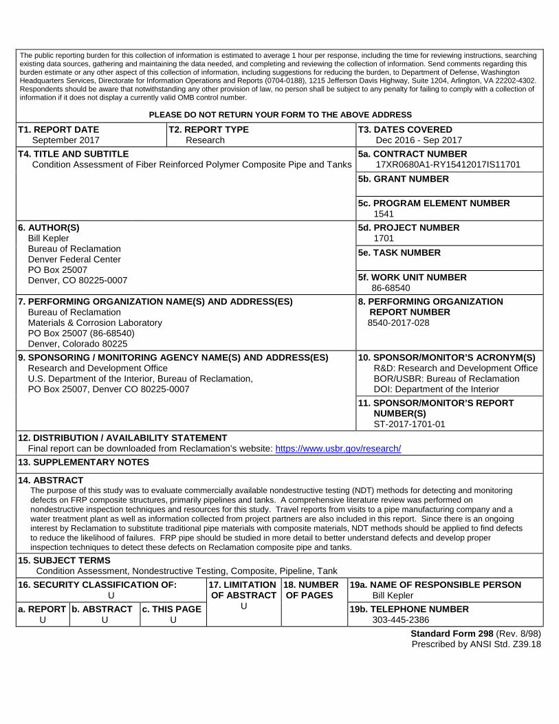
The public reporting burden for this collection of information is estimated to average 1 hour per response, including the time for reviewing instructions, searching existing data sources, gathering and maintaining the data needed, and completing and reviewing the collection of information. Send comments regarding this burden estimate or any other aspect of this collection of information, including suggestions for reducing the burden, to Department of Defense, Washington Headquarters Services, Directorate for Information Operations and Reports (0704-0188), 1215 Jefferson Davis Highway, Suite 1204, Arlington, VA 22202-4302. Respondents should be aware that notwithstanding any other provision of law, no person shall be subject to any penalty for failing to comply with a collection of information if it does not display a currently valid OMB control number.
PLEASE DO NOT RETURN YOUR FORM TO THE ABOVE ADDRESS T1. REPORT DATE
September 2017 T2. REPORT TYPE
Research T3. DATES COVERED
Dec 2016 - Sep 2017 T4. TITLE AND SUBTITLE
Condition Assessment of Fiber Reinforced Polymer Composite Pipe and Tanks 5a. CONTRACT NUMBER
17XR0680A1-RY15412017IS11701 5b. GRANT NUMBER 5c. PROGRAM ELEMENT NUMBER
1541 6. AUTHOR(S)
Bill Kepler Bureau of Reclamation Denver Federal Center PO Box 25007 Denver, CO 80225-0007
5d. PROJECT NUMBER 1701
5e. TASK NUMBER 5f. WORK UNIT NUMBER
86-68540 7. PERFORMING ORGANIZATION NAME(S) AND ADDRESS(ES)
Bureau of Reclamation Materials & Corrosion Laboratory PO Box 25007 (86-68540) Denver, Colorado 80225
8. PERFORMING ORGANIZATION REPORT NUMBER 8540-2017-028
9. SPONSORING / MONITORING AGENCY NAME(S) AND ADDRESS(ES) Research and Development Office U.S. Department of the Interior, Bureau of Reclamation, PO Box 25007, Denver CO 80225-0007
10. SPONSOR/MONITOR’S ACRONYM(S) R&D: Research and Development Office BOR/USBR: Bureau of Reclamation DOI: Department of the Interior
11. SPONSOR/MONITOR’S REPORT NUMBER(S) ST-2017-1701-01
12. DISTRIBUTION / AVAILABILITY STATEMENT Final report can be downloaded from Reclamation’s website: https://www.usbr.gov/research/
13. SUPPLEMENTARY NOTES
14. ABSTRACT The purpose of this study was to evaluate commercially available nondestructive testing (NDT) methods for detecting and monitoring defects on FRP composite structures, primarily pipelines and tanks. A comprehensive literature review was performed on nondestructive inspection techniques and resources for this study. Travel reports from visits to a pipe manufacturing company and a water treatment plant as well as information collected from project partners are also included in this report. Since there is an ongoing interest by Reclamation to substitute traditional pipe materials with composite materials, NDT methods should be applied to find defects to reduce the likelihood of failures. FRP pipe should be studied in more detail to better understand defects and develop proper inspection techniques to detect these defects on Reclamation composite pipe and tanks.
15. SUBJECT TERMS Condition Assessment, Nondestructive Testing, Composite, Pipeline, Tank
16. SECURITY CLASSIFICATION OF: U
17. LIMITATION OF ABSTRACT
U
18. NUMBER OF PAGES
19a. NAME OF RESPONSIBLE PERSON Bill Kepler
a. REPORT U
b. ABSTRACT U
c. THIS PAGE U
19b. TELEPHONE NUMBER 303-445-2386
Standard Form 298 (Rev. 8/98) Prescribed by ANSI Std. Z39.18

U.S. Department of the Interior Bureau of Reclamation Research and Development Office Denver, Colorado September 2017
Technical Memorandum No. 8540-2017-028
Condition Assessment of FRP Composite Pipe and Tanks Research and Development Office Science and Technology Program Final Report ST-2017-1701-01

Disclaimer Information in this report may not be used for advertising or promotional purposes. The data and findings should not be construed as an endorsement of any product or firm by the Bureau of Reclamation, department of interior, or federal government. The products evaluated in this report were evaluated for purposes specific to the Bureau of Reclamation mission. Reclamation gives no warranties or guarantees, expressed or implied, for the products evaluated in this report, including merchantability or fitness for a particular purpose.
Mission Statements The U.S. Department of the Interior protects America’s natural resources and heritage, honors our cultures and tribal communities, and supplies the energy to power our future. The mission of the Bureau of Reclamation is to manage, develop, and protect water and related resources in an environmentally and economically sound manner in the interest of the American public.
BUREAU OF RECLAMATION Technical Service Center, Denver, Colorado Materials and Corrosion Laboratory, 86-68540 Technical Memorandum No. 8540-2017-028
Condition Assessment of FRP Composite Pipe and Tanks Final Report ST-2017-1720-01
Prepared: William Kepler, Ph.D., P.E. Manager, Materials and Corrosion Laboratory, 86-68540
Date
Reviewed: Kurt Von Fay, BSCE, MBA Civil Engineer, Concrete, Geotechnical, & Structural Laboratory, 86-68530
Date
Reviewed: Jonathan Trovillion Materials Engineer, US Army ERDC-CERL
Date
Reviewed: Jeffrey Ryan Materials Engineer, US Army ERDC-CERL
Date
Technical Approval: Daryl Little, Ph.D. Materials Engineer, Materials and Corrosion Laboratory, 86-68540
Date
Peer Reviewed: Bobbi Jo Merten, Ph.D. Civil Engineer, Materials and Corrosion Laboratory, 86-68540
Date

Peer Review Documentation From TSC Guidelines: http://intra.do.usbr.gov/~tsc/guidance/operating/op-guide.pdf (page 18)
Project and Document Information
Project Name
Condition Assessment of FRP Composite Pipe and Tanks
WOID Z1701
Document Condition Assessment of FRP Composite Pipe and Tanks
Document Date September 2017
Document Author/Preparer William Kepler, Ph.D., P.E.
Peer Reviewer Bobbi Jo Merten, Ph.D.
For Reclamation disseminated reports, a disclaimer is required for final reports and other research products, this language can be found in the peer review policy: "This information is distributed solely for the purpose of pre-dissemination peer review under applicable information quality guidelines. It has not been formally disseminated by the Bureau of Reclamation. It does not represent and should not be construed to represent Reclamation's determination or policy."
Review Certification
Peer Reviewer: I have reviewed the assigned items/sections(s) noted for the above document and believe them to be in accordance with the project requirements, standards of the profession, and Reclamation policy.
Reviewer Signature
Date Reviewed

Technical Memorandum No. 8540-2017-028 Condition Assessment of Fiber Reinforced Polymer Composite Pipe and Tanks
Final Report ST-2017-1720-01
i
Executive Summary The Bureau of Reclamation (Reclamation) began specifying composite structures over half a century ago. These structures include fiber reinforced polymer (FRP) pipeline and tanks. Currently, there is no guidance in place for the inspection of existing or newly installed structures to reduce the likelihood of failures. Also, the rate of new installations of composites is increasing. An inspection program is required to evaluate the condition of composite structures and identify defects that occur during service and manufacturing, shipping and handling, and installation. The previous Reclamation Technical Memorandum No. MERL-2015-032 reviewed the state of the art for composite pipeline materials. The document identified the need for improved quality assurance through non-destructive evaluation (NDE) techniques and other tests. NDE inspection methods also allow structure owners to evaluate the condition of FRP pipe and tanks and identify defects before failure occurs. Prompt repairs of defects will lead to improved safety, reduced loss of resources, and increased service life of structures. The purpose of this scoping study was to review literature and other information sources about NDE methods for detecting and monitoring defects on FRP composite pipe and tanks. It was conducted in collaboration with the U.S. Army Corps of Engineers. The study is a comprehensive literature review containing:
• Reclamation’s history with glass fiber reinforced polymer composite pipe. • Inspection techniques. • Resources for nondestructive testing of pipe and tanks. • Travel report – Flowtite (Thompson Pipe Group), Zachary, Louisiana. • Travel report – Leadville Mine Drainage Tunnel Water Treatment Plant,
Leadville, Colorado. • Recommendations for future work.

Technical Memorandum No. 8540-2017-028 Condition Assessment of Fiber Reinforced Polymer Composite Pipe and Tanks
Final Report ST-2017-1720-01
iii
Acronyms % percent
°C degree Celsius
ASTM American Society for Testing and Materials
AWWA American Water Works Association cm centimeter
FRP fiber reinforced polymer
GRP glass reinforced polymer
GFRP glass fiber reinforced polymer
ISO International Organization for Standardization
km kilometer
LLC Limited Liability Company
m meter
MPa megapascal
NDE nondestructive evaluation
NDT nondestructive testing
Reclamation Bureau of Reclamation
RPM reinforced polymer mortar
U.S. United States
USACE U.S. Army Corps of Engineers
UT ultrasonic testing
UV ultra-violet
Technical Memorandum No. 8540-2017-028 Condition Assessment of Fiber Reinforced Polymer Composite Pipe and Tanks Final Report ST-2017-1720-01
iv
Contents Introduction ............................................................................................................6
Reclamation’s History with FRP Pipe .................................................................6
FRP Inspection Techniques ..................................................................................8
Resources Providing Nondestructive Testing for Pipe and Tanks ..................10
Reclamation NDE on FRP Pipe and Tanks .......................................................11
Leadville Mine Drainage Tunnel Water Treatment Plant ................................11 Yuma Desalting Plant ......................................................................................11
Summary and Recommendations .......................................................................12
References .............................................................................................................15
Tables Table 1. — Reclamation RPM Pipe Database [6] ...................................................7
Table 2. — FRP Inspection Techniques ..................................................................9
Table 3. — FRP Inspection Resources ..................................................................10
Figures Figure 1. — Digital tap hammer [33] ....................................................................10
Figure 2.—GRP aboveground pipelines at Yuma Desalting Plant. .......................12
Figure A-1.—GFRP pipe couplings/fittings with gaskets for sealing .....................2
Figure A-2.—GFRP tee connector ..........................................................................2
Figure A-3.—Flowtite filament wound manufacturing process ..............................3
Figure A-4.—Continuous fiberglass thread woven and wrapped over Mylar .........3
Figure A-5.—Chopped glass fiber waste .................................................................4
Figure A-6.—Heating system to cure resin .............................................................4
Figure A-7—Cutting pipe to the required length .....................................................5
Figure A-8.—Lowering the pipe for testing ............................................................5
Technical Memorandum No. 8540-2017-028 Condition Assessment of Fiber Reinforced Polymer Composite Pipe and Tanks
Final Report ST-2017-1720-01
v
Figure A-9.—Checking the pipe and removing Mylar ............................................6
Figure A-10.—Stamping the pipe identification (diameter (24 inch or 61 cm), pressure (250 psi or 2 MPa), and stiffness (36 psi or 0.25 MPa)) ...............6
Figure A-11.—Hydro-tester station .........................................................................7
Figure A-12.—Samples for mechanical testing .......................................................8
Figure A-13.— Mechanical properties tester (29,000 N load at 5% deflection) .....8
Figure A-14.—pressure testing of the fittings .........................................................9
Figure A-15.—Fabrication process of flanges .......................................................10
Figure A-16.—Woven fiberglass cloths ................................................................11
Figure B-1.—Acid and caustic tanks used for water treatment with their manufacturing information ..........................................................................4
Figure B-2.—Visual inspection of the acid tank interior .........................................5
Technical Memorandum No. 8540-2017-028 Condition Assessment of Fiber Reinforced Polymer Composite Pipe and Tanks Final Report ST-2017-1720-01
6
Introduction Fiber reinforced polymer (FRP) composites are materials consisting of fibers in a polymer matrix. They can be used to fabricate pipe and tanks by embedding fiber reinforcements (glass, carbon, aramid, etc.) in cured thermosetting resin. The composite structure can contain multiple components including aggregate, fillers (granular or platelet), thixotropic agents, and pigments and dyes. Fibers can be orientated to provide specific structural properties. There are many advantages of using FRP composite material over traditional materials, which include: corrosion resistance, light weight, durability, and strength. In addition, the thermosetting resins used, such as epoxy, vinyl ester, or polyester, provide heat-resistance up to 260 °C operating temperatures [1]. The resins also provide a smooth interior surface that results in a low friction factor for pipe (high Hazen-Williams roughness coefficient). A Norwegian study also identified FRP as being more environmentally friendly than its alternatives, including ferrous, polyethylene, and polyvinyl chloride pipes [2]. FRP composite systems are typically higher initial cost compared to other materials. However, the initial cost is mitigated by considering the life cycle cost, and as a result, using FRP composites may be less expensive than other construction materials. FRP composite use grew exponentially during recent years in many industries and for many applications, including pipe, tanks, vaults, and gates. The composite market in North America reached $1.2 billion in 2013 for pipe and tanks [3]. The increased use of FRP composites requires a re-evaluation of inspection technologies for quality control/quality assurance during fabrication as well as for assessing in service performance. Possible manufacturing, shipping, handling, or installation defects to inspect for include delaminations, fiber splitting, fracture, waviness, resin voids, pores, and micro-cracks. In-service condition assessments of composites detects changes to the material as result of damage or degradation. The subject study focuses on FRP pipe and tanks in alignment with Reclamation’s growing use. FRP pipe are available in diameters from under 10 cm to greater than 3 m with available pressure classes for the smaller pipe exceeding 7 MPa. The pipe and fitting sizes come in standard sizes or can be custom fabricated to meet a project’s design requirements. FRP tanks are designed and manufactured in a variety of sizes depending on the gallon capacity. The FRP tank properties make them a superior choice for a wide range of liquid storage and process applications [4-5].
Reclamation’s History with FRP Pipe Reclamation has a long history with a specific FRP pipe type called reinforced polymer mortar (RPM) pipe. This pipe incorporates a sand filler to economically increase wall thickness and pipe stiffness for large diameter (greater than 30 cm), buried applications. It is also manufactured for non-pressure applications such as sewers and gravity-flow drains.
Technical Memorandum No. 8540-2017-028 Condition Assessment of Fiber Reinforced Polymer Composite Pipe and Tanks
Final Report ST-2017-1720-01
7
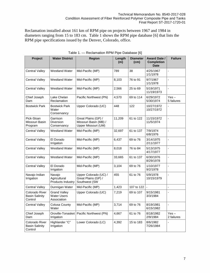
Reclamation installed about 161 km of RPM pipe on projects between 1967 and 1984 in diameters ranging from 15 to 183 cm. Table 1 shows the RPM pipe database [6] that lists the RPM pipe specifications issued by the Denver, Colorado, office.
Table 1. — Reclamation RPM Pipe Database [6] Project Water District Region Length
(m) Diameter
(cm) Award Date / Completion
Date
Failure
Central Valley Westland Water Mid-Pacific (MP) 789 38 4/25/1967 1/1/1978
-
Central Valley Westland Water Mid-Pacific (MP) 8,103 76 to 91 9/7/1967 1/1/1978
-
Central Valley Westland Water Mid-Pacific (MP) 2,566 25 to 69 5/19/1971 11/19/1973
-
Chief Joseph Dam
Lake Chelan Reclamation
Pacific Northwest (PN) 4,570 69 to 114 6/29/1972 5/30/1974
Yes – 5 failures
Bostwick Park Bostwick Park Water Conservancy
Upper Colorado (UC) 448 122 10/27/1972 10/27/1972
-
Pick-Sloan Missouri Basin Program
Garrison Diversion Conservancy
Great Plains (GP) / Missouri Basin (MB) / Upper Missouri (UM)
11,209 61 to 122 11/15/1972 11/5/1974
-
Central Valley Westland Water Mid-Pacific (MP) 32,697 61 to 137 7/9/1974 6/8/1976
-
Central Valley El Dorado Irrigation
Mid-Pacific (MP) 6,437 69 to 76 3/14/1975 2/11/1977
-
Central Valley Westland Water Mid-Pacific (MP) 8,018 76 to 84 5/13/1975 4/17/1977
-
Central Valley Westland Water Mid-Pacific (MP) 33,665 61 to 137 6/30/1976 8/29/1978
-
Central Valley El Dorado Irrigation
Mid-Pacific (MP) 3,104 69 to 76 1/10/1977 9/2/1978
-
Navajo Indian Irrigation
Navajo Agricultural Products Industry
Upper Colorado (UC) / Great Plains (GP) / Southwest (SW
455 61 to 76 5/9/1978 10/15/1979
-
Central Valley Dunnigan Water Mid-Pacific (MP) 1,423 107 to 122 - -
Colorado River Basin Salinity Control
Grand Valley Water Users Association
Upper Colorado (UC) 7,219 69 to 107 9/15/1981 3/3/1984
-
Central Valley Colusa County Water
Mid-Pacific (MP) 3,714 69 to 76 8/19/1981 6/15/1982
-
Chief Joseph Dam
Oroville-Tonasket Irrigation
Pacific Northwest (PN) 4,667 61 to 76 8/18/1982 2/9/1984
Yes – 2 failures
Colorado River Basin Salinity Control
Highlander “C” Irrigation
Lower Colorado (LC) 4,392 15 to 183 8/6/1982 7/26/1984
-
Technical Memorandum No. 8540-2017-028 Condition Assessment of Fiber Reinforced Polymer Composite Pipe and Tanks Final Report ST-2017-1720-01
8
Reclamation experienced several unexplained ruptures of RPM pipe leading to a temporary moratorium in 1990, which applied to the use of FRP pipe for Reclamation projects [7]. The pipe failures were later attributed to the manufacturing process, which preceded the development of American Water Works Association (AWWA) standards for FRP pipe. Reclamation also used glass reinforced polymer (GRP) composite pipe, which is a type of FRP pipe and is better known as fiberglass pipe. It is also synonymous with the acronym GFRP. Reclamation’s FRP moratorium also applied to this pipe type although it has provided good service with no reported failures. In 1991, partial lifting of the moratorium by Reclamation allowed the use of pipe following the AWWA Standard for Fiberglass Pressure Pipe, C950-88 [8], on a case-by-case basis. In 1997, the FRP moratorium was lifted completely. This allowed for GRP pipe design in accordance with AWWA M45 Fiberglass Pipe Design Manual [9] and manufacture in accordance with AWWA C950-95 Standard [10]. Reclamation Technical Memorandum No. MERL-2015-032 contains a detailed discussion on the FRP moratorium and the manufacturing process improvements that allowed for use of this pipe type at Reclamation [11]. Recently, some Reclamation clients requested GRP pipe to be included as a pipe type option in new construction. This includes 26 kilometers (km) of 61-centimeter (cm) diameter Flowtite GRP pipe for the Navajo-Gallup Water Supply Project Reach 22B in New Mexico [12]. Reclamation has additional projects in the design phase with FRP listed as an option for sections of the pipelines. A summary of the trip report for travel to a Flowtite manufacturing facility is included in Appendix A.
FRP Inspection Techniques FRP composites are subject to several degradation modes and manufacturing defects. Possible composite damage types for FRP structures include delamination, mechanical damage, osmotic blistering, and stress corrosion [13]. Some damage result from manufacturing whereas others result from the environment or physical impacts during service. Understanding the damage types ensures the use of appropriate inspection techniques. For a summary of factors affecting FRP composites durability in service [14], see Chapter 4 of the Feasibility Review of FRP Materials for Structural Applications, prepared in 2010 for the U.S. Army Corps of Engineers (USACE). Non-destructive evaluation (NDE), also known as non-destructive testing (NDT), is of great interest for FRP inspection. The advantage of NDE techniques is that it provides structural integrity information without disturbing or altering the integrity. Conversely, non-NDE techniques may test a structure to failure. Both approaches are valuable, but NDE is necessary for quality assurance of new installations and inspection of existing structures. The advancement of NDE technology for existing structures and the improved awareness of the potential issues are too often in response to failures.
Technical Memorandum No. 8540-2017-028 Condition Assessment of Fiber Reinforced Polymer Composite Pipe and Tanks
Final Report ST-2017-1720-01
9
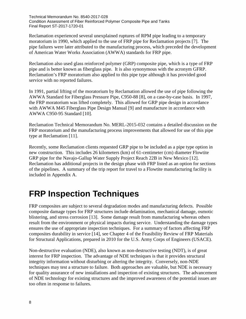
NDE techniques can be classified as contact or non-contact. Examples of contact techniques include ultrasonic testing (UT), eddy current, electromagnetic, and penetrants, whereas non-contact techniques include visual, thermography, radiography, and holography [15]. Each technique has its advantages and intended applications, particularly regarding the FRP damage types that it can detect. Table 2 summarizes relevant NDE techniques for pipe and tanks. For descriptions of some of the most common NDE techniques, see Chapter 7 within the Feasibility Review of FRP Materials for Structural Applications [14].
Table 2. — FRP Inspection Techniques NDE
Technique Underlying Principles Types of Defects Detected Standards References
Visual Qualitative indication of damage, primarily by sight observation
Blisters, delamination, discoloring, porosity, surface
features, engineering drawing disparities
ASTM D2563 [1,16,17]
Pressure Pressurizing a pipe structure allows for defect determination and hydrostatic design
stress evaluation
Cracks, delamination, fiber waviness
ASTM D1599 ASTM D2992
[1,18,19]
Tapping Physical striking of sensor tool used to identify changes in material stiffness
Delamination - [20]
Ultrasonic Sound waves transmitted into material and reflected waves detect changes in material
properties; low frequencies used to determine wall thickness; high frequencies
resolve defects within matrix that are greater than half of the wavelength
Cracks, delamination, inclusions, wall thickness
- [1,15, 21-24]
Acoustic Emission
Sound waves generated in the material during change in stress; sensors detect and
locate source of event; combination of acousto-ultrasonic resolves degree of
inhomogeneity
Fiber breaks, crack growth, delamination
ASTM E1067 ASTM E1118
[1,15,23,25-28]
Electromagnetic Magnetism or electricity used to induce magnetic fields or currents to detect
changes in material properties
Carbon fiber reinforced composite flaws
[15]
Infrared Thermography
Infrared radiation (thermal radiation) used to resolve changes in the material thermal
conductivity, emissivity, density, and specific heat capacity within the composite;
use of external heat source increases contrast
Cracks, voids, surface thickness irregularities
[29-34]
Radiography X-ray or gamma-ray radiation used to resolve changes in material densities within
the composite; use of penetrants can increase contrast
Cracks, delamination, inclusions, fiber waviness and orientation, voids, wall
thickness
[12,15,35,36]
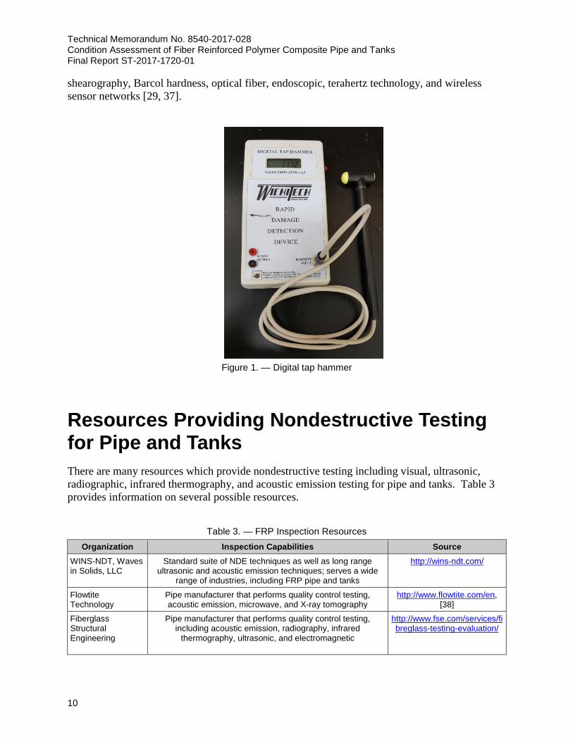
Figure 1 provides an example of a digital tap hammer, which is a hand-held instrument for performing the tapping technique at the manufacturer or during field inspections. Other NDE techniques to consider for application to FRP materials include acoustic-ultrasonic,
Technical Memorandum No. 8540-2017-028 Condition Assessment of Fiber Reinforced Polymer Composite Pipe and Tanks Final Report ST-2017-1720-01
10
shearography, Barcol hardness, optical fiber, endoscopic, terahertz technology, and wireless sensor networks [29, 37].
Figure 1. — Digital tap hammer
Resources Providing Nondestructive Testing for Pipe and Tanks There are many resources which provide nondestructive testing including visual, ultrasonic, radiographic, infrared thermography, and acoustic emission testing for pipe and tanks. Table 3 provides information on several possible resources.
Table 3. — FRP Inspection Resources Organization Inspection Capabilities Source
WINS-NDT, Waves in Solids, LLC
Standard suite of NDE techniques as well as long range ultrasonic and acoustic emission techniques; serves a wide
range of industries, including FRP pipe and tanks
http://wins-ndt.com/
Flowtite Technology
Pipe manufacturer that performs quality control testing, acoustic emission, microwave, and X-ray tomography
http://www.flowtite.com/en, [38]
Fiberglass Structural Engineering
Pipe manufacturer that performs quality control testing, including acoustic emission, radiography, infrared
thermography, ultrasonic, and electromagnetic
http://www.fse.com/services/fibreglass-testing-evaluation/
Technical Memorandum No. 8540-2017-028 Condition Assessment of Fiber Reinforced Polymer Composite Pipe and Tanks
Final Report ST-2017-1720-01
11
Organization Inspection Capabilities Source UTComp Developed UltraAnalytix™ technique for ultrasonic tank and
pipe inspection https://www.utcomp.ca/inspec
tion/
TSP Environmental Licenses UltraAnalytix™ ultrasonic for FRP tank inspection https://tspenvironmental.com/
US Army Corps of Engineers
Practices several FRP inspection NDE techniques, including visual inspection, tapping, infrared thermography, and
ultrasonic testing; equipment list includes the Thermal Wave Imaging, Inc., VoyageIR Pro, which provides a compact, cost-effective thermographic flaw detection system and a Sonatest
Masterscan 380 for ultrasonic testing
[14]
Reclamation NDE on FRP Pipe and Tanks Reclamation has several facilities that utilize NDE for pipe and tanks. Below is a brief description of two of them.
Leadville Mine Drainage Tunnel Water Treatment Plant
FRP storage tanks providing enhanced chemical resistance at the Leadville, Colorado, mine site include:
• Two horizontal GRP tanks containing 50% sodium hydroxide, 20,820 liters capacity each
• Two vertical GRP tanks containing 10% sulfuric acid, 20,820 liters capacity each
• Two vertical GRP tanks containing 10% sodium hydroxide, 20,820 liters capacity each
• Four GRP tanks, part of the gravity sand filtration system
Visual inspection of all tanks is performed annually. Repair is required when delamination of the C-veil is found. C-veil is a thin ply of fiberglass which contain C Glass, a chemically resistant glass that withstands acid and alkaline environments. These tanks were first inspected using video inspection conducted by URS Corporation engineers during 2010 plant assessment. Due to observations resulting from the video inspection, FreeWater Systems, LLC, was hired to inspect the tanks. The degree of damage was sufficient that immediate repairs were performed to prevent a sudden failure. Damage inside the tanks was evidenced by discoloration and bubbling. FreeWater Systems did all the repairs to the C-veils and locations where deterioration was found. Bubbling was caused when the sodium hydroxide had soaked into the fibers and created a bumpy surface. Reclamation performed a site visit on May 25, 2017; a summary of the trip report is included in Appendix B.
Yuma Desalting Plant
The GRP aboveground pipeline at Yuma Desalting Plant range between 20 to 30 years old. There are also some new pipelines that are shown in figure 2. Pipelines are mostly used for low

Technical Memorandum No. 8540-2017-028 Condition Assessment of Fiber Reinforced Polymer Composite Pipe and Tanks Final Report ST-2017-1720-01
12
and moderate pressure water (~0.7 MPa) as well as for cleaning chemicals. All the pipelines were produced by Koch Fiberglass. Failures have only occurred at the fittings (taper fit elbows and quick key couplings) and faulty assembly procedures (disengagement of the fittings due to bad bonding practice) during original construction. Visual inspection has been performed whenever a problem occurs by disassembling the pipe. Visual inspection has found no evidence of degradation of the pipe. There are also some 30-year-old GRP tanks at Yuma Desalting Plant and they have not shown any issues.
Figure 2. — GRP aboveground pipelines at Yuma Desalting Plant.
Summary and Recommendations Reclamation is currently responsible for the operation and maintenance of hundreds of miles of composite pipelines. Also, composite materials are being included as an option for new pipelines more often. Performing condition assessment and acceptance inspections of these pipelines is critical to their success. This report provides examples of Reclamations experience with FRP pipe and tanks with a focus on the types of applicable NDE techniques. Sophisticated NDE techniques provide support for the development of FRP materials and manufacturing quality control. Several NDE techniques are now available for field inspection of existing structures. Visual inspection and ultrasonic
Technical Memorandum No. 8540-2017-028 Condition Assessment of Fiber Reinforced Polymer Composite Pipe and Tanks
Final Report ST-2017-1720-01
13
testing provide the most field-ready options, while a digital tap hammer, acoustic emission, and infrared thermography can provide additional information or verifications. This research included two inspections to build Reclamation’s understanding and expertise with manufacturing and maintenance inspections of FRP materials. The trip reports appear as appendices. FRP composite defect types should be studied in more detail along with appropriate inspection tools and testing procedures. Proper inspection processes should be developed and practiced in the laboratory and then used to monitor quality and to detect defects on Reclamation FRP pipe and tanks in the field. A detailed, standardized process should be developed that specifies the types of NDE methods to use for inspections of new or existing FRP components. Periodic inspections, normally at 3- to 5-year intervals, are recommended to monitor for any changes.

Technical Memorandum No. 8540-2017-028 Condition Assessment of Fiber Reinforced Polymer Composite Pipe and Tanks
Final Report ST-2017-1720-01
15
References [1] Arabi Hassen, A., U.K. Vaidya, and F. Britt. 2015. Structural Integrity of
Fiber Reinforced Plastic Piping. Materials Evaluation, Vol. 73, No. 7, pp 918-929.
[2] Fjeldhus, K.S. 2012. Selecting Materials for Potable Water Pipes from an
Environmental Perspective: Life Cycle Assessments of Four Chosen Pipe Materials. Universitetet for miljø- og biovitenskap.
[3] Aylward, P. 2014. Pipe and Tank Market Poised for Growth. Composite
Manufacturing. [4] Hassen, A.A., A. Poudel, T.P. Chu, M. Yester, and U.K. Vaidya. 2014.
Tracing Defects in Glass Fiber/Polypropylene Composites using Ultrasonic C-scan and X-ray Computed Tomography Methods. American Society for Nondestructive Testing Annual Conference, Charleston, South Carolina.
[5] Khan, T., N. Rao, F. Amir, and M. Khan. 2014. Novel Damage Diagnosis
Algorithms for Aerospace Nondestructive Testing Data using Ultrasonic Testing Technique. Proceedings of the American Society for Nondestructive Testing 23rd Research Symposium, Minneapolis, Minnesota, pp 67–71.
[6] Reclamation. Reinforced Polymer Mortar Pipe Database. Retrieved from
Bureau of Reclamation Intranet: Civil Engineering\D8140\Group Databases\Pipe Data Base.
[7] Cook, F. 1997. Use of Fiberglass Pipe on Reclamation projects. [8] American Water Works Association. 1989. AWWA – C950-88 Standard
for Fiberglass Pressure Pipe. [9] American Water Works Association. 2013. AWWA – M45 Fiberglass
Pipe Design Manual. [10] American Water Works Association. 1996. AWWA – C950-95 Standard
for Fiberglass Pressure Pipe. [11] Tordonato, D. 2015. Composite Materials for Pipelines, Technical
Memorandum No. MERL-2015-032. Bureau of Reclamation. [12] Swihart, J.J. 2016. Fiberglass Pipe Literature Review, Interim Report
ST-2016-9777-01. Bureau of Reclamation.
Technical Memorandum No. 8540-2017-028 Condition Assessment of Fiber Reinforced Polymer Composite Pipe and Tanks Final Report ST-2017-1720-01
16
[13] Reichhold. FRP Inspection Guide: An Inspection Guide for FRP
Equipment. Accessed June 2017 from http://pdf.directindustry.com/pdf/ reichhold/frp-inspection-guide/37855-560854.html.
[14] GangaRao, H.V.S., Vijay, P.V. 2010. Feasibility Review of FRP Materials
for Structural Applications. West Virginia University, Morgantown, WV. Submitted to U.S. Army Corps of Engineers.
[15] Gholizadeh, S. 2016. A Review of Nondestructive Testing Methods of
Composite Materials, Procedia Structural Integrity, 1. pp 50-57. [16] MIL-HDBK-17-3F. 2002. Composite Materials Handbook. Volume 3.
Polymer Matrix Composite Materials Usage, Design, and Analysis. Department of Defense Handbook.
[17] American Society for Testing and Materials. 2015. ASTM D2563 –
Standard Practice for Classifying Visual Defects in Glass-Reinforced Plastic Laminate Parts.
[18] American Society for Testing and Materials. 2014. ASTM D1599 –
Standard Test Method for Resistance to Short-Time Hydraulic Pressure of Plastic Pipe, Tubing, and Fittings.
[19] American Society for Testing and Materials. 2012. ASTM D2992 –
Standard Practice for Obtaining Hydrostatic or Pressure Design Basis for Fiberglass (Glass-Fiber-Reinforced Thermosetting-Resin) Pipe and Fittings. 2012. American Society for Testing and Materials.
[20] Kotha. M. 2013. Nondestructive Evaluation of Concrete and Composite
Bridges Using Infrared Thermography and Ground Penetrating Radar. Master of Science in Civil Engineering, Department of Civil and Environmental Engineering Morgantown, West Virginia.
[21] Clarkson, G.E. 2014. Baseline Values for Non-Destructive Structural
Evaluation of Glass Reinforced Composites. Composites and Advanced Materials Expo, Orlando, Florida.
[22] Norwegian Oil and Gas Association, 055. 1997. Norwegian Oil and Gas
Recommended Guidelines for Nondestructive Testing of Glass Fiber Reinforced Polymer Pipe Systems and Tanks. Norwegian Oil and Gas Association, Sandnes, Norway.
[23] Clarkson, G.E. 2015. Nondestructive Condition Assessment of Fiberglass
Reinforced Structures. Proceedings of the Water Environment Federation. pp 1037-1052.
Technical Memorandum No. 8540-2017-028 Condition Assessment of Fiber Reinforced Polymer Composite Pipe and Tanks
Final Report ST-2017-1720-01
17
[24] Hassen, A.A., A. Poudel, T.P. Chu, M. Yester, and U.K. Vaidya. 2014.
Tracing Defects in Glass Fiber/Polypropylene Composites using Ultrasonic C-scan and X-ray Computed Tomography Methods. American Society for Nondestructive Testing Annual Conference, Charleston, South Carolina.
[25] Conlisk, P. 1992. Design Improvements in FRP Chemical Process
Equipment Resulting from Acoustic Emission Examination. 4th International Symposium on Acoustic Emission From Composite Materials, Seattle, Washington.
[26] Kosmann, N., J.M. Karsten, M. Schuett, K. Schulte, and B. Fiedler. 2015.
Determining the Effect of Voids in GFRP on the Damage Behavior Under Compression Loading using Acoustic Emission. Composites Part B: Engineering, Vol. 70, No. 1, pp 184–188.
[27] American Society for Testing and Materials. 2016. ASTM E1118 /
E1118M – Standard Practice for Acoustic Emission Examination of Reinforced Thermosetting Resin Pipe.
[28] American Society for Testing and Materials. 2011. ASTM E1067 /
E1067M – Standard Practice for Acoustic Emission Examination of Fiberglass Reinforced Plastic Resin Tanks/Vessels.
[29] Zhu, Y.-K., G.-Y. Tian, R.S. Lu, and H. Zhang. 2011. A Review of
Optical Nondestructive Testing Technologies. Sensors, 11, pp 7773-7798.
[30] Busse, G., and A. Rosencwaig. 1980. Subsurface Imaging with
Photoacoustics. Applied Physics Letters, Vol. 36, No. 10, pp 815–816. [31] G. Giorleo and C. Meola. 2002. Comparison between Pulsed and
Modulated Thermography in Glass-epoxy Laminates. NDT&E International, Vol. 35, No. 5, pp 287–292.
[32] Meola, C., and G.M. Carlomagno. 2010. Impact Damage in Glass Fiber
Reinforced Polymer: New Insights with Infrared Thermography. Composites Part A: Applied Science and Manufacturing, Vol. 41, No. 12, pp 1839–1847.
[33] Nance, S.P., Y. Zhang, and T.P. Chu. 2007. Determination of Fiber
Orientation in C/C with Infrared Thermography. Society for Experimental Mechanics Annual Conference and Exposition on Experimental and Applied Mechanics, Springfield, Massachusetts.
Technical Memorandum No. 8540-2017-028 Condition Assessment of Fiber Reinforced Polymer Composite Pipe and Tanks Final Report ST-2017-1720-01
18
[34] Wright, M. 2006. Ultrasonic Nondestructive Evaluation of GFRP Pipes – Sure2GriP – Quality Assurance and Structural Evaluation of GFRP Pipes Horizontal Research Activities Involving Smes Co-operative Research Project Funded by the European Commission. 9th European Conference on Nondestructive Testing, Berlin, Germany.
[35] Nevadunsky, J.J., J.J. Lucas, and M.J. Salkind. 1975. Early Fatigue
Damage Detection in Composite Materials. Journal of Composite Materials, Vol. 9, pp 764–769.
[36] Green, W.H., and P. Sincebaugh. 2001. Nondestructive Evaluation of
Complex Composites using Advanced Computed Tomography Imaging, ARL-TR-2400. Army Research Laboratory, Aberdeen Proving Ground, Maryland.
[37] Hufenbach, W., R. Böhm, M. Thieme, and T. Tyczynski. 2011. Damage
Monitoring in Pressure Vessels and Pipelines Based on Wireless Sensor Networks. Procedia Engineering, 10, pp 340-345.
[38] Didierjean S., and G. Lubineau. NDT Experience and On-Going Projects
Applied to FLOWTITE© Glass Reinforced Pipes. Accessed June 2017 from http://www.ndt.net/article/mendt2012/papers/NDT-061.pdf.


APPENDIX A
TRAVEL REPORT – FLOWTITE (THOMPSON PIPE GROUP)
FACTORY VISIT, ZACHARY, LOUISIANA

Technical Memorandum No. 8540-2017-028 Condition Assessment of Fiber Reinforced Polymer
Composite Pipe and Tanks Final Report ST-2017-1720-01
B-1
Date: 4/4/2017 Travelers: Atousa Plaseied (8540), Jay Swihart (8540), Nick Clough (8140),
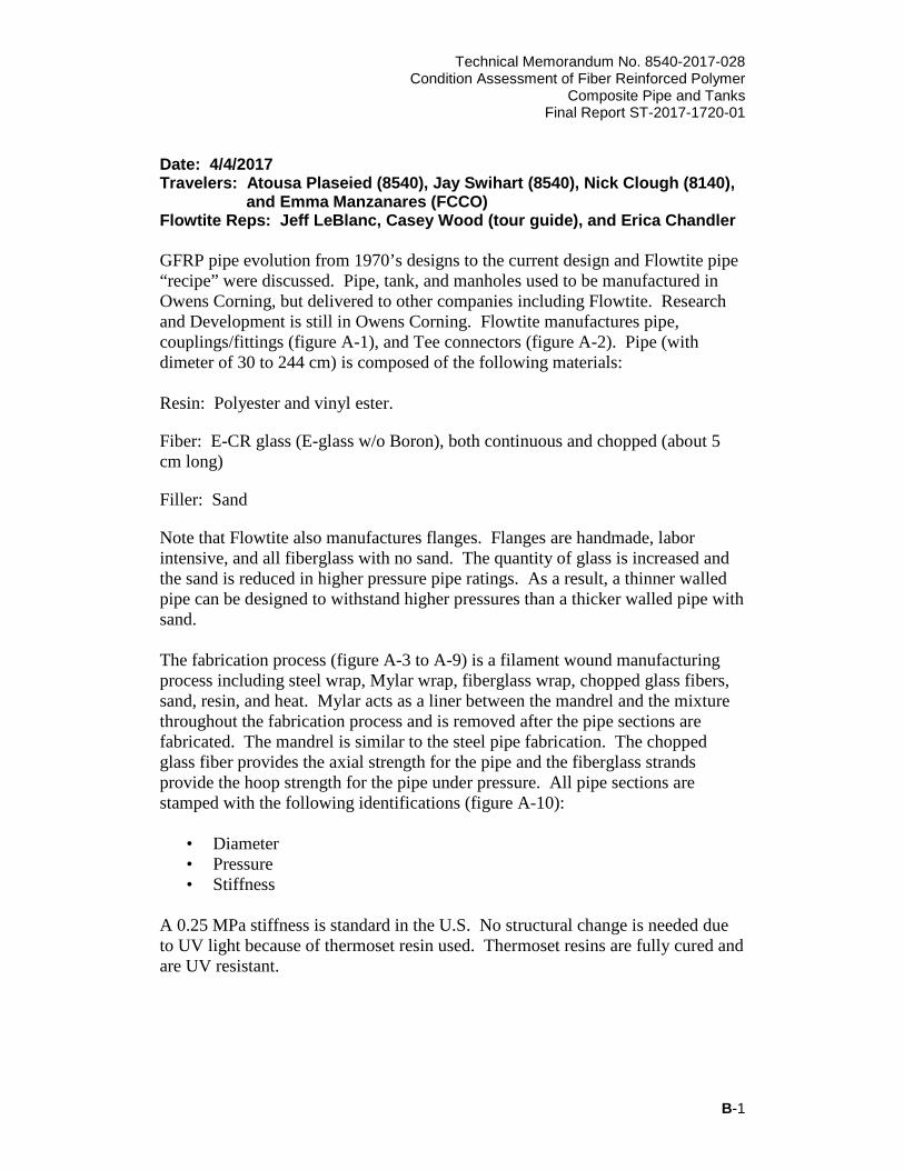
and Emma Manzanares (FCCO) Flowtite Reps: Jeff LeBlanc, Casey Wood (tour guide), and Erica Chandler GFRP pipe evolution from 1970’s designs to the current design and Flowtite pipe “recipe” were discussed. Pipe, tank, and manholes used to be manufactured in Owens Corning, but delivered to other companies including Flowtite. Research and Development is still in Owens Corning. Flowtite manufactures pipe, couplings/fittings (figure A-1), and Tee connectors (figure A-2). Pipe (with dimeter of 30 to 244 cm) is composed of the following materials: Resin: Polyester and vinyl ester.
Fiber: E-CR glass (E-glass w/o Boron), both continuous and chopped (about 5 cm long)
Filler: Sand
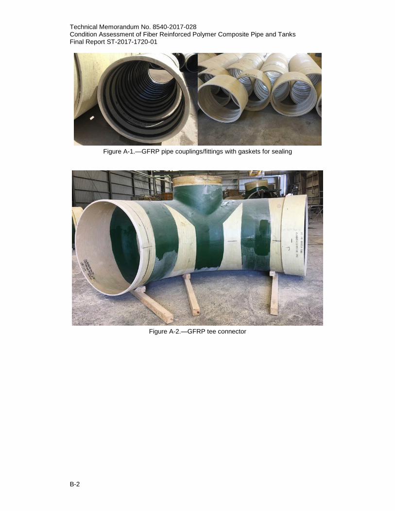
Note that Flowtite also manufactures flanges. Flanges are handmade, labor intensive, and all fiberglass with no sand. The quantity of glass is increased and the sand is reduced in higher pressure pipe ratings. As a result, a thinner walled pipe can be designed to withstand higher pressures than a thicker walled pipe with sand. The fabrication process (figure A-3 to A-9) is a filament wound manufacturing process including steel wrap, Mylar wrap, fiberglass wrap, chopped glass fibers, sand, resin, and heat. Mylar acts as a liner between the mandrel and the mixture throughout the fabrication process and is removed after the pipe sections are fabricated. The mandrel is similar to the steel pipe fabrication. The chopped glass fiber provides the axial strength for the pipe and the fiberglass strands provide the hoop strength for the pipe under pressure. All pipe sections are stamped with the following identifications (figure A-10):
• Diameter • Pressure • Stiffness
A 0.25 MPa stiffness is standard in the U.S. No structural change is needed due to UV light because of thermoset resin used. Thermoset resins are fully cured and are UV resistant.
Technical Memorandum No. 8540-2017-028 Condition Assessment of Fiber Reinforced Polymer Composite Pipe and Tanks Final Report ST-2017-1720-01
B-2
Figure A-1.—GFRP pipe couplings/fittings with gaskets for sealing
Figure A-2.—GFRP tee connector

Technical Memorandum No. 8540-2017-028 Condition Assessment of Fiber Reinforced Polymer
Composite Pipe and Tanks Final Report ST-2017-1720-01
B-3
Figure A-3.—Flowtite filament wound manufacturing process
Figure A-4.—Continuous fiberglass thread woven and wrapped over Mylar

Technical Memorandum No. 8540-2017-028 Condition Assessment of Fiber Reinforced Polymer Composite Pipe and Tanks Final Report ST-2017-1720-01
B-4
Figure A-5.—Chopped glass fiber waste
Figure A-6.—Heating system to cure resin
Technical Memorandum No. 8540-2017-028 Condition Assessment of Fiber Reinforced Polymer
Composite Pipe and Tanks Final Report ST-2017-1720-01
B-5
Figure A-7—Cutting pipe to the required length
Figure A-8.—Lowering the pipe for testing
Technical Memorandum No. 8540-2017-028 Condition Assessment of Fiber Reinforced Polymer Composite Pipe and Tanks Final Report ST-2017-1720-01
B-6
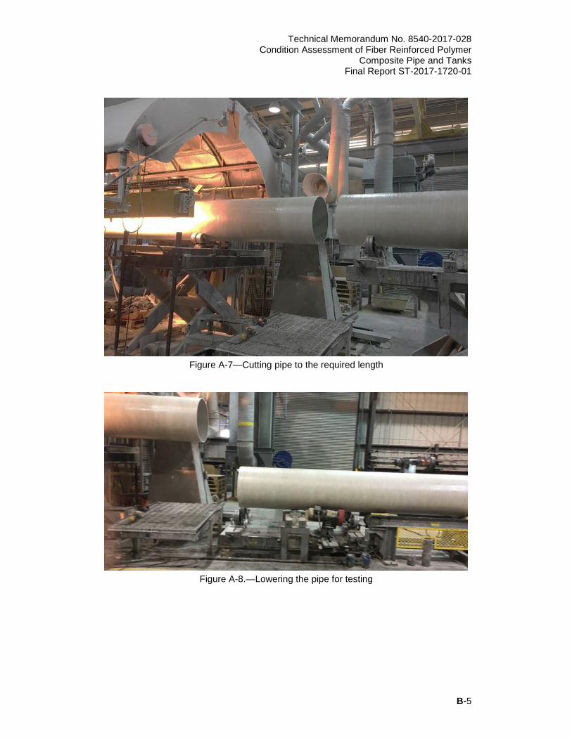
Figure A-9.—Checking the pipe and removing Mylar
Figure A-10.—Stamping the pipe identification
(diameter (24 inch or 61 cm), pressure (250 psi or 2 MPa), and stiffness (36 psi or 0.25 MPa))
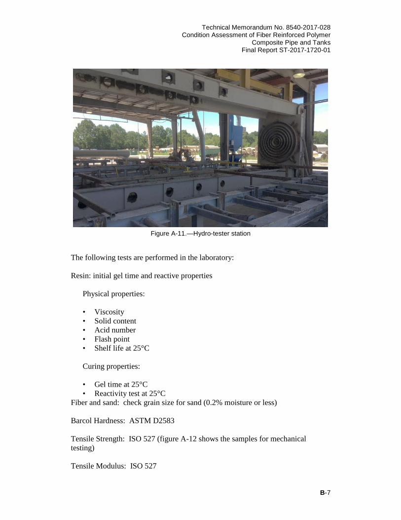
After the pipe fabrication, the pipe sections move to a calibration station: the ends are calibrated/adjusted to fit in the Flowtite couplings. Pipe sections are then forwarded to the hydro-tester station (figure A-11) for pressure testing with water. All pipe sections are tested to twice the rated pressure and held for two minutes. The setup for hydro-testing the GFRP pipe is similar to steel pipe hydro-testing. The pipe fails if it loses pressure.
Technical Memorandum No. 8540-2017-028 Condition Assessment of Fiber Reinforced Polymer
Composite Pipe and Tanks Final Report ST-2017-1720-01
B-7
Figure A-11.—Hydro-tester station
The following tests are performed in the laboratory: Resin: initial gel time and reactive properties
Physical properties: • Viscosity • Solid content • Acid number • Flash point • Shelf life at 25°C Curing properties: • Gel time at 25°C • Reactivity test at 25°C
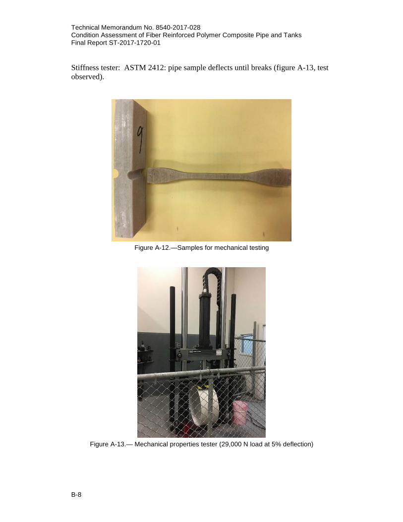
Fiber and sand: check grain size for sand (0.2% moisture or less) Barcol Hardness: ASTM D2583 Tensile Strength: ISO 527 (figure A-12 shows the samples for mechanical testing) Tensile Modulus: ISO 527
Technical Memorandum No. 8540-2017-028 Condition Assessment of Fiber Reinforced Polymer Composite Pipe and Tanks Final Report ST-2017-1720-01
B-8
Stiffness tester: ASTM 2412: pipe sample deflects until breaks (figure A-13, test observed).
Figure A-12.—Samples for mechanical testing
Figure A-13.— Mechanical properties tester (29,000 N load at 5% deflection)
Technical Memorandum No. 8540-2017-028 Condition Assessment of Fiber Reinforced Polymer
Composite Pipe and Tanks Final Report ST-2017-1720-01
B-9
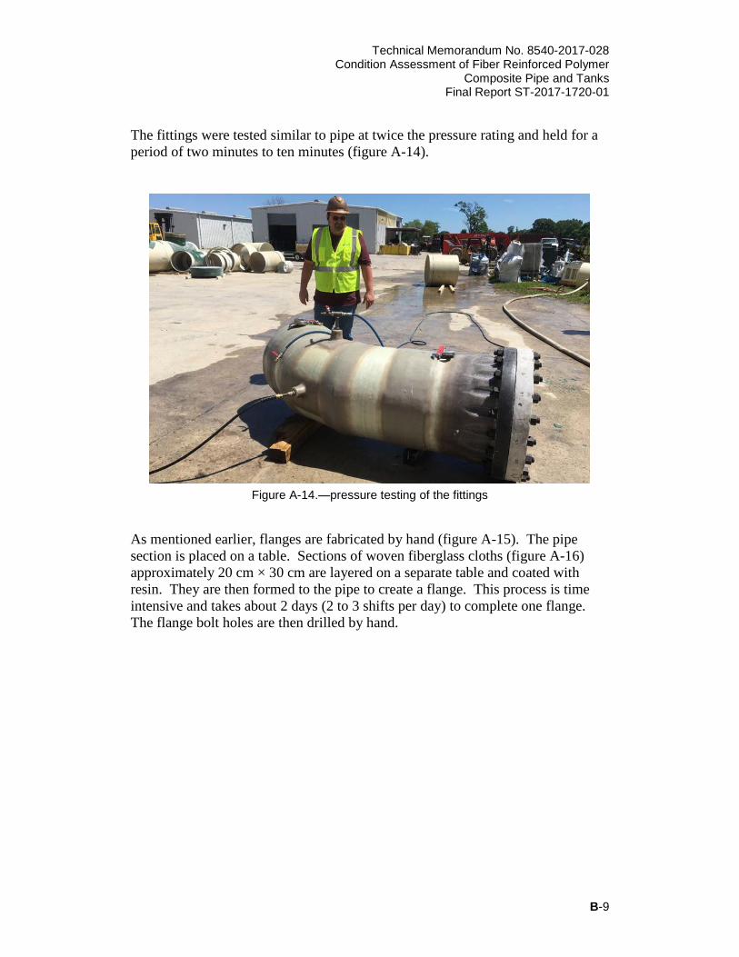
The fittings were tested similar to pipe at twice the pressure rating and held for a period of two minutes to ten minutes (figure A-14).
Figure A-14.—pressure testing of the fittings
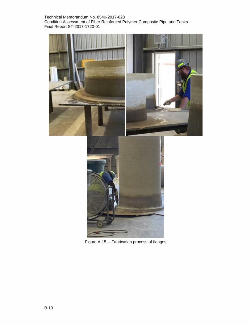
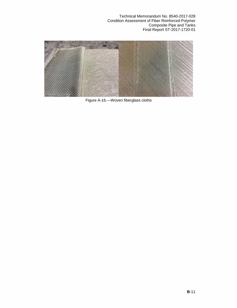
As mentioned earlier, flanges are fabricated by hand (figure A-15). The pipe section is placed on a table. Sections of woven fiberglass cloths (figure A-16) approximately 20 cm × 30 cm are layered on a separate table and coated with resin. They are then formed to the pipe to create a flange. This process is time intensive and takes about 2 days (2 to 3 shifts per day) to complete one flange. The flange bolt holes are then drilled by hand.
Technical Memorandum No. 8540-2017-028 Condition Assessment of Fiber Reinforced Polymer Composite Pipe and Tanks Final Report ST-2017-1720-01
B-10
Figure A-15.—Fabrication process of flanges
Technical Memorandum No. 8540-2017-028 Condition Assessment of Fiber Reinforced Polymer
Composite Pipe and Tanks Final Report ST-2017-1720-01
B-11
Figure A-16.—Woven fiberglass cloths

APPENDIX B
TRAVEL REPORT – LEADVILLE MINE DRAINAGE
TUNNEL WATER TREATMENT PLANT, LEADVILLE, COLORADO


Technical Memorandum No. 8540-2017-028 Condition Assessment of Fiber Reinforced Polymer
Composite Pipe and Tanks Final Report ST-2017-1720-01
C-1
Date: 5/25/2017 Travelers: Atousa Plaseied (8540), Jay Swihart (8540), and Christine
Henderson (8540) Leadville Mine Drainage Tunnel Water Treatment Plant Rep: Jenelle
Stefanic Inspector: Ron Harris (Free Water Systems) Visual Inspection of acid and caustic tanks were performed 5 years after 2012 inspection and 4 year after 2013 repair in May 2017. The reports from 2012 and 2017 inspections, prepared by Ron Harris, Western Underground Fiberglass Service, a division of Free Water Systems, LLC. Tank Inspection and Repair Protocol – Leadville Mine Drainage Tunnel Water Treatment Plant – December 2012 Inspection: Two tanks were inspected: 1) Dilute sulfuric acid tank – Design Tanks – Dion 6631 – 3 m D x 4 m T – mfd 12/2000 This tank has a failing liner. Many deteriorated areas appear throughout the entire interior surface. The bottom cap joint and areas around all the penetrations and manway show severe deterioration. There is also a series of cracks appearing on one side, which appear to be possible shipping damage. Structurally, this tank appears intact. There is a mixer mounted on the outside top of this tank, with a platform bolted directly into the top of the tank at each end with common lag bolts. These bolts have wallowed out and allow the mixer to shake when in operation. This tank requires relining and the addition of two support platforms on top for the mixer. Penetrations on this tank are: 61 cm Manway 2 – 8 cm Flanged nozzles 1 – 5 cm Flanged nozzle 1 – 10 cm Nozzle 1 – 5 cm Threaded nipple – plugged Repair Protocol: The entire interior of this tank will need to be sanded, with particular attention to the deteriorated areas and the areas around the bottom cap and penetrations. After sanding, two thorough acetone wipes will be needed to prepare for layers of penetrating resin. Layers of penetrating resin need to be applied until there is no fiber visible on the interior surface. After letting the penetrating resin harden thoroughly, all areas treated will require an additional sanding, followed again by
Technical Memorandum No. 8540-2017-028 Condition Assessment of Fiber Reinforced Polymer Composite Pipe and Tanks Final Report ST-2017-1720-01
C-2
twice wiping down with acetone. Final application will be a layer of Derakane resin over C-veil, with the final, top layer, requiring an added surfacing agent to promote complete curing. The manway flange on this tank is also deteriorated and will require the same treatment, plus a final sanding, to insure a good seal. The manway blank appears intact, not requiring any work. Mounting brackets for the mixer will need to be added after adding a gusset to each top corner. This gusset should “wrap” around from the horizontal top surface to the vertical side of the tank for several inches and be built up with succeeding layers of 57 g structural mat to a thickness of at least 0.6 cm. An FRP channel, 8 cm x 3 cm and 5 cm longer than the pump bracket, should then be laminated onto the gusset, giving adequate clearance underneath for the nuts on the mounting bolts. Rubber washers would be recommended between the mounting and the pump bracket to absorb vibration. 2) NaOH storage Tank – Palmer Tanks – Hetron 922 – 2 m D x 5 m T – mfd 9/23/2005 This tank shows a few small areas of deterioration around the penetrations and the manway. These areas need to be resurfaced. Structurally this tank appears sound and should provide many more years of service. Those deteriorated areas are all where hand lamination was used during production and require the same basic repair protocol as the interior of the acid tank. The manway flange shows some minor deterioration and should be resurfaced and refaced. The manway blank appears intact. Penetrations on this tank are: 61 cm Manway 1 – 8 cm Nozzle 2 – 5 cm Nozzles Tank Inspection and Repair Protocol – Leadville Mine Drainage Tunnel Water Treatment Plant – May 2017 1) Tank Description: Dilute Sulfuric Acid Tank AS4 Dimensions: 3 m D x 4 m T Shape: Cylinder Function: Dilution/Metering Material: Fiberglass: FRP – Dion 6631 FRP Type: Helical ______ Chop Hoop: ______ Cast: X Other: _______ Steel Type: Welded: _______ Riveted: ________ Other: ________ General Condition: Previous Repairs Relined in 2013 appear intact – no exposed fiber visible Floor: Good Joint: Good Seams: N/A Top: Not Inspected, Indoor Fittings: Good
Technical Memorandum No. 8540-2017-028 Condition Assessment of Fiber Reinforced Polymer
Composite Pipe and Tanks Final Report ST-2017-1720-01
C-3
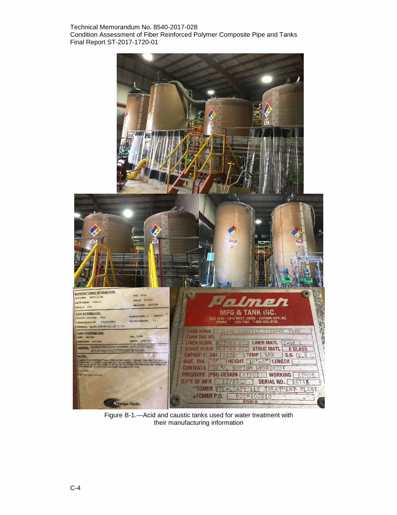
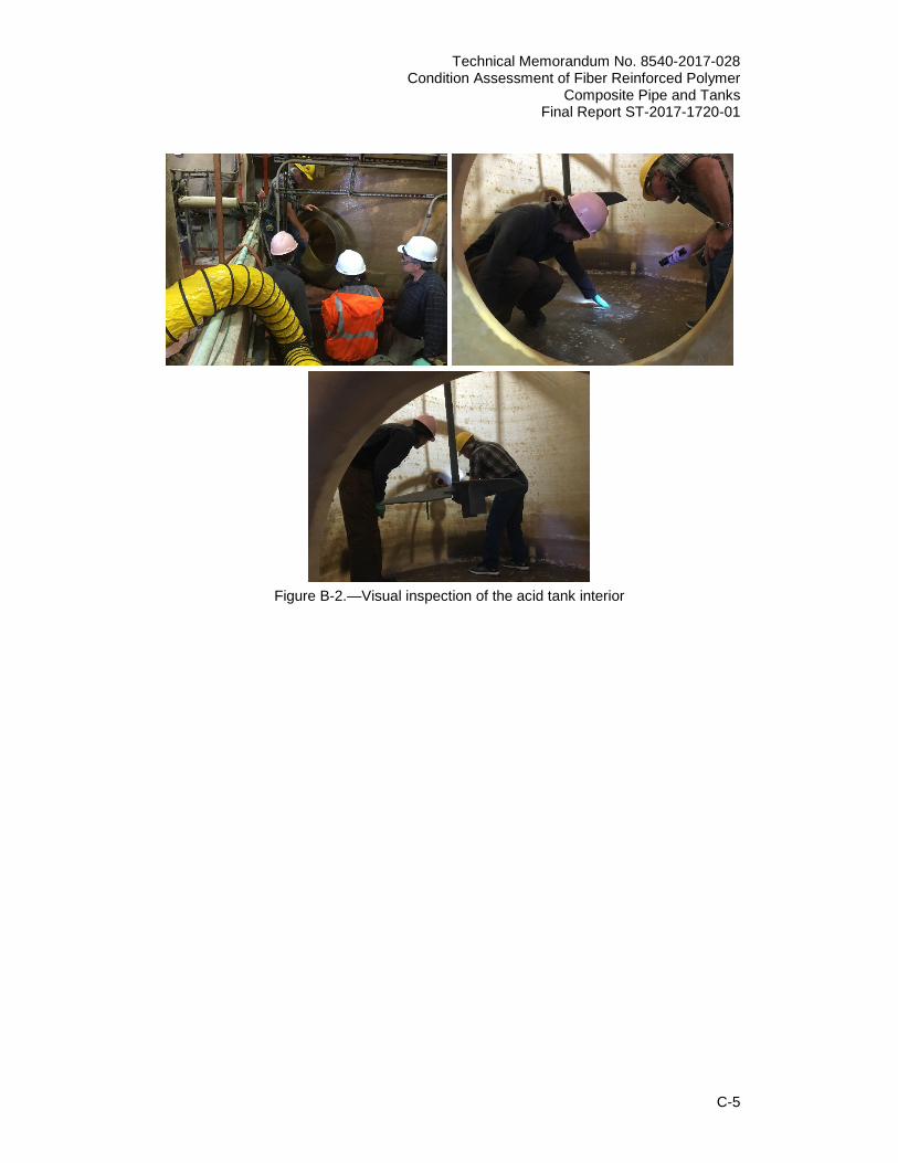
Notes: Recommend Follow up Inspection in five years Maximum 2) Tank Description: NaOH Storage Dilute Tank CS4 Dimensions: 2 m D x 5 m T Shape: Cylinder Function: Caustic Storage/Metering Material: Fiberglass: Hetron 922 FRP Type: Helical X Chop Hoop: ______ Cast: _______ Other: _______ General Condition: Good (Tank was re-lined in 2015) Floor: Good Joint: Good Seams: Good Top: Not Inspected – Indoors Fittings: Good Notes: Recommend re-inspection in 3-5 years Inspection was performed on both acid and caustic tanks (figures B-1 and B-2). These tanks are used for chemical treatment and cleaning water. Visual inspection was a reliable and easy method to detect blisters, air pockets, voids, and delamination in FRP tanks. Digital tap hammer could also be used as a tool for detecting delamination by change in the sound.
Technical Memorandum No. 8540-2017-028 Condition Assessment of Fiber Reinforced Polymer Composite Pipe and Tanks Final Report ST-2017-1720-01
C-4
Figure B-1.—Acid and caustic tanks used for water treatment with
their manufacturing information
Technical Memorandum No. 8540-2017-028 Condition Assessment of Fiber Reinforced Polymer
Composite Pipe and Tanks Final Report ST-2017-1720-01
C-5
Figure B-2.—Visual inspection of the acid tank interior