Embed Size (px)
Citation preview
HAL Id: hal-02545762https://hal.archives-ouvertes.fr/hal-02545762v2
Submitted on 15 Mar 2021
HAL is a multi-disciplinary open accessarchive for the deposit and dissemination of sci-entific research documents, whether they are pub-lished or not. The documents may come fromteaching and research institutions in France orabroad, or from public or private research centers.
L’archive ouverte pluridisciplinaire HAL, estdestinée au dépôt et à la diffusion de documentsscientifiques de niveau recherche, publiés ou non,émanant des établissements d’enseignement et derecherche français ou étrangers, des laboratoirespublics ou privés.
Condition Assessment of an historical structure : theCNIT Vault in Paris
Bruno Godart, Franziska Schmidt, Brioist Jean-Jacques Brioist, Jean PaulDeveaud, Fernando Dias
To cite this version:Bruno Godart, Franziska Schmidt, Brioist Jean-Jacques Brioist, Jean Paul Deveaud, Fernando Dias.Condition Assessment of an historical structure : the CNIT Vault in Paris. IABSE Symposium,Synergy of Culture and Civil Engineering - History and Challenges, May 2020, Wroclaw, Poland. 8p. �hal-02545762v2�
1
CONDITION ASSESSMENT OF AN HISTORICAL STRUCTURE: THE CNIT
VAULT IN PARIS
B. Godart1, F. Schmidt1, J.J. Brioist2, J.P. Deveaud3, F. Dias4
1Paris-Est University, IFSTTAR, Champs sur Marne, France. 2Cerema, Direction Nord-Picardie, Lille, France. 3Cerema, Direction Centre-Est, Bron, France 4DIRIF, Paris, France
e-mail: [email protected]
SUMMARY
As part of the extension of line E of the Regional Express Rail Network of Paris, it was decided to create an
underground station under the CNIT (National Center for Industries and Techniques) located in the business
district of La Défense. This project clearly raises the question of the stability of the main vault of the CNIT
under the effect of any soil movement caused by the proposed works. This vault, which still holds the world
record of span length, was built between 1956 and 1958 on a project of Nicolas Esquillan.
The article briefly describes the history of the vault construction, and presents the results of finite element
modelling and geotechnical calculations, the results of the destructive and non-destructive tests conducted on
the vault, the control of the geometry and reinforcement, the few observed disorders, the condition of the ties
and their tension. It draws conclusions on the general condition of the structure from the point of view of its
strength and durability. The quality of the work carried out in 1958, both on site and in the design office, the
attention paid to the materials chosen and the work processes on site, make this structure age very well.
Keywords: CNIT vault, reinforced concrete, condition, assessment, testing, durability.
1. INTRODUCTION
As part of the extension of the E line of the Regional Express Rail Network of Paris, it was decided to create
an underground station under the CNIT (National Center for Industries and Techniques) located in the business
district of La Défense. This project clearly raises the question of the stability of the main vault of the CNIT
under the effect of possible soil movement caused by the proposed works. This article presents the results of a
thorough study conducted by Cerema and Ifsttar to expertise the structure before starting the works.
1.1 Historical aspects
The CNIT was designed by the architects Robert-Edouard Camelot, Jean de Mailly and Bernard Zehrfuss at
La Defense, a little hill west from Paris, at the end of the royal road designed by Le Nôtre, in the exact extension
of the Louvre perspective [1]. The engineering part was directed by Nicolas Esquillan for a joint venture of
Balency, Coignet and Boussiron companies. This building, now classified as a historical monument, was
inaugurated by General de Gaulle in 1958. It still holds the world record of span length (218 m).
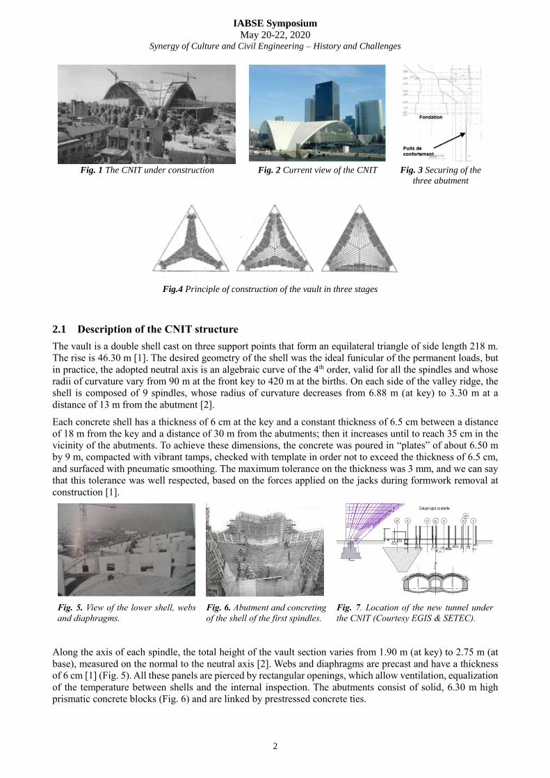
In the 1980s, the original monumental architecture of the vault was modified by the burial of its abutments,
due to the construction of the great slab of La Défense over the road network (1978) and the re-development
of the interior space (1988). The construction of new levels of underground car parks under the CNIT was an
opportunity to secure the abutments by digging shafts designed to take all the pressure of the vault in the event
of a total rupture of the prestressed ties connecting the three abutments (Fig.3).
IABSE Symposium
May 20-22, 2020 Synergy of Culture and Civil Engineering – History and Challenges
2
Fig. 1 The CNIT under construction Fig. 2 Current view of the CNIT Fig. 3 Securing of the
three abutment
Fig.4 Principle of construction of the vault in three stages
2.1 Description of the CNIT structure
The vault is a double shell cast on three support points that form an equilateral triangle of side length 218 m.
The rise is 46.30 m [1]. The desired geometry of the shell was the ideal funicular of the permanent loads, but
in practice, the adopted neutral axis is an algebraic curve of the 4th order, valid for all the spindles and whose
radii of curvature vary from 90 m at the front key to 420 m at the births. On each side of the valley ridge, the
shell is composed of 9 spindles, whose radius of curvature decreases from 6.88 m (at key) to 3.30 m at a
distance of 13 m from the abutment [2].
Each concrete shell has a thickness of 6 cm at the key and a constant thickness of 6.5 cm between a distance
of 18 m from the key and a distance of 30 m from the abutments; then it increases until to reach 35 cm in the
vicinity of the abutments. To achieve these dimensions, the concrete was poured in “plates” of about 6.50 m
by 9 m, compacted with vibrant tamps, checked with template in order not to exceed the thickness of 6.5 cm,
and surfaced with pneumatic smoothing. The maximum tolerance on the thickness was 3 mm, and we can say
that this tolerance was well respected, based on the forces applied on the jacks during formwork removal at
construction [1].
Fig. 5. View of the lower shell, webs
and diaphragms.
Fig. 6. Abutment and concreting
of the shell of the first spindles.
Fig. 7. Location of the new tunnel under
the CNIT (Courtesy EGIS & SETEC).
Along the axis of each spindle, the total height of the vault section varies from 1.90 m (at key) to 2.75 m (at
base), measured on the normal to the neutral axis [2]. Webs and diaphragms are precast and have a thickness
of 6 cm [1] (Fig. 5). All these panels are pierced by rectangular openings, which allow ventilation, equalization
of the temperature between shells and the internal inspection. The abutments consist of solid, 6.30 m high
prismatic concrete blocks (Fig. 6) and are linked by prestressed concrete ties.
IABSE Symposium
May 20-22, 2020 Synergy of Culture and Civil Engineering – History and Challenges
3
The vault was built in three main phases by group of three spindles (Fig. 4). These latter were built on
scaffolding and then jacked in order to translate the scaffolding for the next phase. As the pressure in the jacks
(10 jacks of 300 tons located near the abutment) increased by steps, the tension in the tendons of the prestressed
ties was also progressively increased. Additional jacking of each group of 3 spindles was further performed to
compensate for the subsequent creep deformations of the different spindles.
2. INSPECTION AND GEOMETRY OF THE VAULT
2.1. Detailed inspection of the intrados of the vault
The detailed inspection of the intrados of the vault was carried out by the company SITES with the
SCANSITES 3D® process according to the following methodology:
creation of a three-dimensional model from laser scanner surveys of the intrados, with assembly via
tacheometry of the scanning stations;
high-resolution photographic scanning of the entire intrados, from several shooting stations;
processing of photographs and realization of photographic panoramas with very high resolution;
inspection of photographic panoramas, recording of the observations and entry in the database;
data processing and creation of mapping.
This detailed inspection made it possible to establish an exhaustive and precise record of its condition that can
be used as reference in subsequent operations on this exceptional structure. The analysis of the observations
shows that the intrados is generally in good condition:
concerning the risks of falling elements, only a piece of concrete with a length of about 10 cm between
two edges appears to be potentially unstable. This concrete piece had to be removed;
concerning the condition of the constituent materials, the defects - visible corroded steels, concrete
spalls - are small and, with regard to spalls, mainly localized at the ribs. Apparently, having occurred
at the formwork removal, they are not symptomatic of an aging of the reinforced concrete;
concerning the structural functioning, the observed cracks are mostly short, little opened and scattered.
They do not reflect abnormal mechanical functioning of the vault.
2.2 Special Inspection of the cells of the vault
Due to the need of accurate structural modelling of the structure and in order to determinate the expected
behavior of the structure, despite the good health of the internal face of the vault (see previous section), it has
been decided to inspect the cells between the 2 shells of the vault. As inspecting exhaustively all cells was too
heavy, ten cells were selected for inspection: near the supports and near the keys, spread on the three parts of
the vault, near the defaults that have been detected on the intrados. The intrados of the upper shell of the vault
could not be inspected because of the construction method (the formwork was not removed).
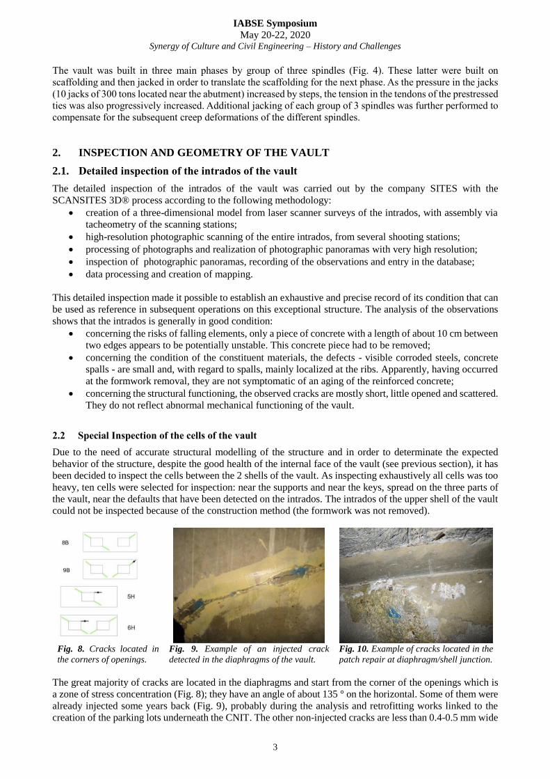
Fig. 8. Cracks located in
the corners of openings.
Fig. 9. Example of an injected crack
detected in the diaphragms of the vault.
Fig. 10. Example of cracks located in the
patch repair at diaphragm/shell junction.
The great majority of cracks are located in the diaphragms and start from the corner of the openings which is
a zone of stress concentration (Fig. 8); they have an angle of about 135 ° on the horizontal. Some of them were
already injected some years back (Fig. 9), probably during the analysis and retrofitting works linked to the
creation of the parking lots underneath the CNIT. The other non-injected cracks are less than 0.4-0.5 mm wide
IABSE Symposium
May 20-22, 2020 Synergy of Culture and Civil Engineering – History and Challenges
4
and can occasionally reach an opening of 0.9 mm. Overall, these cracks do not seem active, and after their
initial creation these cracks do not seem to spread or deviate.
Some cracks are also visible at the junction between the diaphragm and the upper shell. Five of them were
investigated and it appears that the crack affects the patch repair and that under the mortar repair, the crack
does not extend into the diaphragm (Fig. 10). Globally, the general conclusion of this visual inspection of a
sample of cells was the overall good structural condition of the vault.
3. RESULTS OF TESTING
A need for more investigations was highlighted: indeed, while some documents describing the design and
construction methods from the 1950s still exist, the quality of their implementation as well as the ageing of the
materials and the structure are unknown. Therefore, it was decided to investigate the reinforcement, the
concrete and the prestressed ties of the structure.
3.1 Location and condition of reinforcement
The steel reinforcement of the shells consists of weld-mesh panels, installed at mid-depth in the shells. It is
composed of 5.4 mm-wires every 10 cm in the direction of the curvature of the shells, and 4.4 mm- wires every
15 cm in the direction of the span of the shells [3, 4]. This information had to be checked in order to validate
the numerical calculations of the structure. This was done with the help of radar and profometer techniques
[5], in order to obtain a complete 3D image of the reinforcement steels.
This was useful to precise the location and density of reinforcement in the reinforced concrete modelling within
the numerical simulations. Another advantage was that the position of the concrete cores for concrete
assessment could be located.
3.2 Destructive and non-destructive tests on concrete
Destructive and non-destructive tests were undertaken in order to assess the actual current concrete strength
and the condition of the concrete.
3.2.1 Mechanical tests
The concrete was tested all along the construction, thus the characteristics at 7, 28 and 90 days are known. The
initial design calculations were made with a compressive strength of 43 MPa at 90 days [3]. In the present
study, three testing zones were defined (abutment, lower shell and jacking zone), and 3 concrete samples were
cored in each zone to have a statistical representability without damaging much the structure. On these 9
concrete cores, the compressive strength was determined, as well as the numerical values of the Young’s
modulus, the Poisson’s ratio and the thermal dilatation coefficient: the mean measured value of these
parameters were respectively 38.4 GPa, 0.24 and 8.7.10-6/°C.
Concerning the measured values of the compressive strength (see Table 1), a strong variability between the
samples was observed, which could be linked to the vibration method that had been used. Nevertheless, for all
three zones, the measured mean value is higher than the one found in the documentation.
Table 1. Values of compressive strength as measured and as given in the documentation [3].
Tested zone Measured equivalent
resistance Value at 7 days [3] Value at 28 days [3] Value at 90 days [3]
Abutment 43.7 MPa
25.9 MPa 34.7 MPa 41.7 MPa Lower shell 46.9 MPa
Jacking zone 57.8 MPa
3.2.2 Durability and physico-chemical tests
The durability of the concrete was evaluated on site (carbonation, air permeability) and on the 9 samples taken
in the vault (porosity to water and scanning electron microscopy). Based on these results, with a water porosity
IABSE Symposium
May 20-22, 2020 Synergy of Culture and Civil Engineering – History and Challenges
5
varying between 11.8 % and 14 % and an air permeability varying between 0.1 10-16 m2 and 39 10-16 m2, the
durability was assessed as fair according to reference [6]. Indeed, based on these results and taking into account
the exposure class, the remaining lifetime may be evaluated to be between 100 and 120 years. Moreover, as
the penetration of the carbonation front is between 1 and 2 mm, it does not reach the steel reinforcement,
therefore there is no risk of corrosion over a long time.
3.3 Investigations on the prestressed ties
3.3.1 Visual inspection
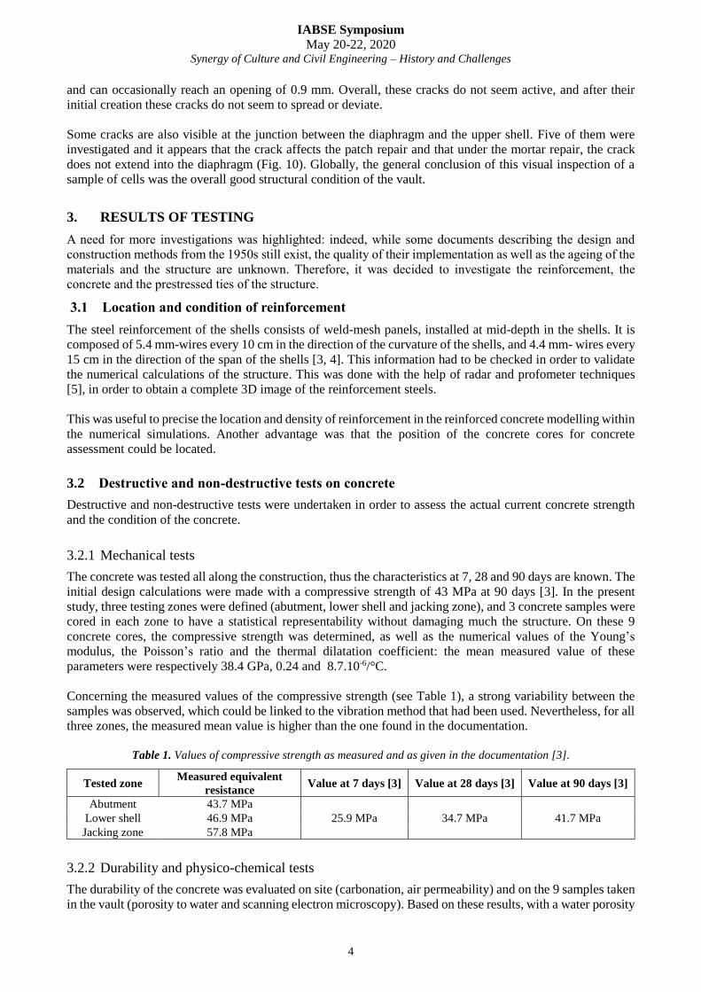
The three prestressed concrete ties are composed of 44 tendons each. Each tendon, made of 24 wires, with 7
mm in diameter, belongs to the Boussiron (BBR) process. It is reported in [2] that these tendons have an
ultimate tensile strength not smaller than 1450 MPa and had been tensioned with 85-ton jacks, which
corresponds to an average stress of 920 MPa inside the steel and a safety factor of 1.33. It was of course of
paramount importance to keep the stress level well below the usual standard value, so as to keep a safety
margin to adjust afterwards the forces in the three ties together and to cope with a possible differential
settlement of the vault. The ties are enclosed in a hollow rectangular concrete box with 20 cm thick walls. The
space between the 44 tendons ducts and the concrete box was filled with sand, in order to protect the tendons
against fire in case of arson. The first step of investigation was then to do four 90 × 60 cm openings in the
concrete wall of the box in some locations, and uncover the ducts (Fig. 11). Each opening could give access to
5 ducts, viz. 10 wires on average.
Fig. 11. Opening of a window in the tie
after a local strengthening by CFRP.
Fig. 12. Good conservation of the
wires after removal of the ducts
Fig. 13. Measure of the tension of a
wire by the crossbow method
The ducts were not corroded. A cursory glance inside the ducts (Fig. 12) has revealed that, except for one (out
of 20), the grout still sticks to the wires and fills the ducts uniformly. No wire was broken and a few spots of
superficial rust were nonetheless observed in some locations. One of the duct was without grout, and,
unsurprisingly, the wires inside were found rusty, and one wire of the tendon was obviously loose.
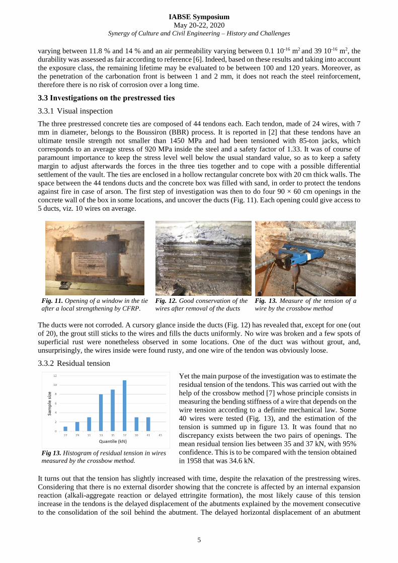
3.3.2 Residual tension
Yet the main purpose of the investigation was to estimate the
residual tension of the tendons. This was carried out with the
help of the crossbow method [7] whose principle consists in
measuring the bending stiffness of a wire that depends on the
wire tension according to a definite mechanical law. Some
40 wires were tested (Fig. 13), and the estimation of the
tension is summed up in figure 13. It was found that no
discrepancy exists between the two pairs of openings. The
mean residual tension lies between 35 and 37 kN, with 95%
confidence. This is to be compared with the tension obtained
in 1958 that was 34.6 kN. Fig 13. Histogram of residual tension in wires
measured by the crossbow method.
It turns out that the tension has slightly increased with time, despite the relaxation of the prestressing wires.
Considering that there is no external disorder showing that the concrete is affected by an internal expansion
reaction (alkali-aggregate reaction or delayed ettringite formation), the most likely cause of this tension
increase in the tendons is the delayed displacement of the abutments explained by the movement consecutive
to the consolidation of the soil behind the abutment. The delayed horizontal displacement of an abutment
IABSE Symposium
May 20-22, 2020 Synergy of Culture and Civil Engineering – History and Challenges
6
deduced from the increase in tension would be of the order of 5 to 7 cm, a value that seems likely. Finally, it
was concluded that we had a satisfactory behaviour of these prestressing ties.
4. FEM MODELLING AND GEOTECHNICAL CALCULATIONS
4.1 Geotechnical study The geotechnical study integrates the strengthening of the vault supports made during the construction of the
car park levels. In the course of the works, the possibility of a failure of one or several horizontal prestressed
ties has been investigated. In the context of these studies, a limit value of the displacement equal to 5 cm and
a limit value of rotation of 2/1000 radians were adopted. The recovery of horizontal efforts generated by the
rupture of one or more ties was ensured by two prestressed concrete shafts having a diameter of 3.5 m on the
East and West supports and 4 m on the North one. Each of the two reinforcement shafts is located in alignment
with the axis of the horizontal ties. The connection between the massive abutments and the reinforcement
shafts is ensured by a prestressed concrete strut that is anchored on a belt equipped with a vertical prestressing.
The digging of tunnels for access to the new railway station located under the CNIT, the excavation of the
station under the last level of the CNIT underground car park and the excavation of the tunnel access shaft
were located in order to avoid any work under or close to the CNIT foundations. According to the drawings,
the distance between the tunnels and the secondary ties is of the order of 7 m. The main ties are about 12 m
from the tunnels. The foundations of the CNIT are located more than 40 m from the tunnels and should
therefore be very little affected by the displacements generated by digging the tunnels.
The distance between the station and the CNIT supports (about 45 m) seems sufficient to overcome, in first
approximation, support movements related to the construction of this one. The secondary ties are located at
about 15 m from the station and it is also a sufficient distance. The mode of construction envisaged for the
station consists of excavating (as a mole) under a slab built at the level of the last level of the underground car
park; this allows to greatly reduce the movement of soils.
4.2 Structural study
Two models of the CNIT structure were realized by the Cerema (formely SETRA):
a modelling of the structure and construction phases with the bar software SETRA-PCP©;
a finite element model of the structure with the EDF software, Code_ASTER©.
These two models are complementary. The bar model allows, compared to the finite element model, to take
into account the construction phasing, the effects of shrinkage and creep, and to have the efforts in the different
elements of the model for the different phases of construction. Using the beam theory, it allows to calculate
the stresses at the various points of the modelled cross-sections. The bar model however reaches its limits of
use for the following points:
some elements are difficult to assimilate with beams (slabs, low slenderness, ...);
the effects of transverse flexion are not taken into account, and therefore are not cumulative to those
of longitudinal bending;
continuous links between spindles are modelled by cross links, with all disadvantages of beam ladder
modelling;
in the anchoring zones of the beams (birth and key), the diffusion of efforts is not correctly considered.
All these points were treated by the finite element model, but only for particular loading cases. For these
loading cases, the finite element model has been introduced to allow a validation of the bar model, or to identify
some singularities. Despite the highlighting of these limitations we can consider the PCP bar model as validated
for the purpose of the study. This validation, as well as the easy taking into account of construction phasing
and delayed effects - which have an important effect for this structure - have made the PCP model the model
for the rest of the study. The finite element model contributes where the PCP model does not allow to consider
certain effects, for example in the vicinity of the births or the key.
IABSE Symposium
May 20-22, 2020 Synergy of Culture and Civil Engineering – History and Challenges
7
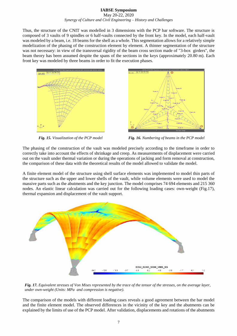
Thus, the structure of the CNIT was modelled in 3 dimensions with the PCP bar software. The structure is
composed of 3 vaults of 9 spindles or 6 half-vaults connected by the front key. In the model, each half-vault
was modeled by a beam, i.e. 18 beams for the shell as a whole. This segmentation allows for a relatively simple
modelization of the phasing of the construction element by element. A thinner segmentation of the structure
was not necessary: in view of the transversal rigidity of the beam cross section made of "3-box girders", the
beam theory has been assumed despite the spans of the sections in the keys (approximately 20.80 m). Each
front key was modeled by three beams in order to fit the execution phases.
Fig. 15. Visualization of the PCP model Fig. 16. Numbering of beams in the PCP model
The phasing of the construction of the vault was modeled precisely according to the timeframe in order to
correctly take into account the effects of shrinkage and creep. As measurements of displacement were carried
out on the vault under thermal variation or during the operations of jacking and form removal at construction,
the comparison of these data with the theoretical results of the model allowed to validate the model.
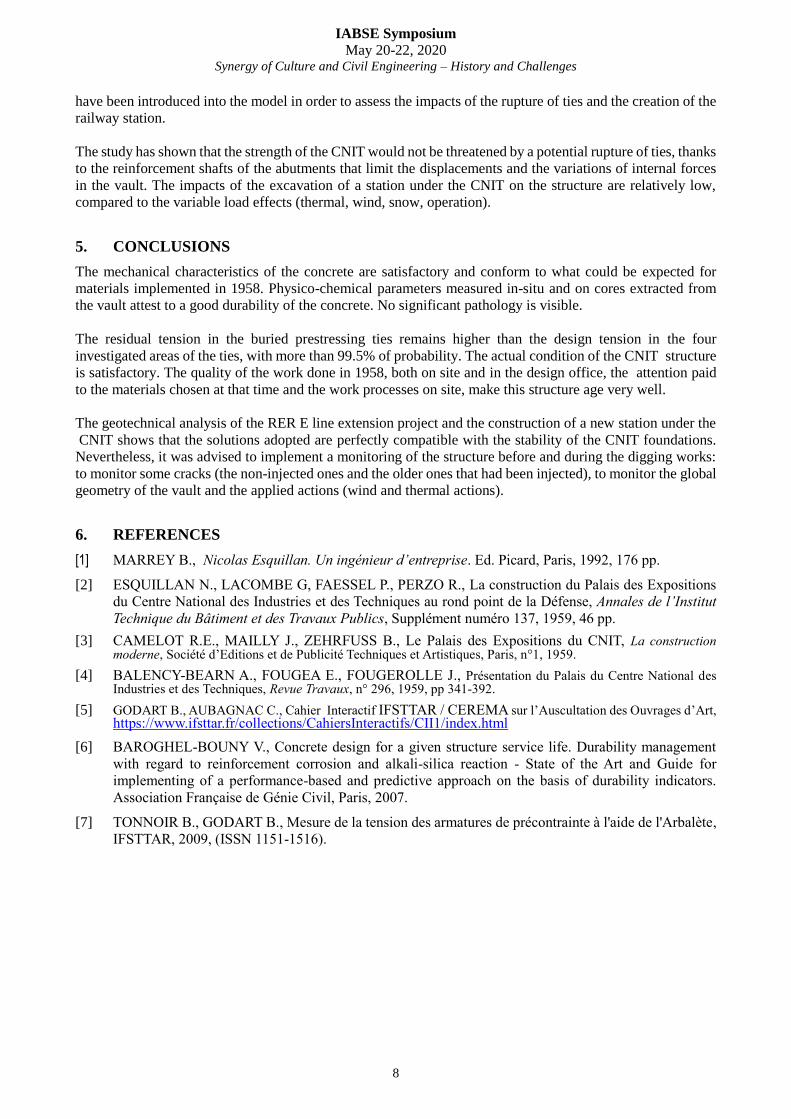
A finite element model of the structure using shell surface elements was implemented to model thin parts of
the structure such as the upper and lower shells of the vault, while volume elements were used to model the
massive parts such as the abutments and the key junction. The model comprises 74 694 elements and 215 360
nodes. An elastic linear calculation was carried out for the following loading cases: own-weight (Fig.17),
thermal expansion and displacement of the vault support.
Fig. 17. Equivalent stresses of Von Mises represented by the trace of the tensor of the stresses, on the average layer,
under own-weight (Units: MPa and compression is negative).
The comparison of the models with different loading cases reveals a good agreement between the bar model
and the finite element model. The observed differences in the vicinity of the key and the abutments can be
explained by the limits of use of the PCP model. After validation, displacements and rotations of the abutments
IABSE Symposium
May 20-22, 2020 Synergy of Culture and Civil Engineering – History and Challenges
8
have been introduced into the model in order to assess the impacts of the rupture of ties and the creation of the
railway station.
The study has shown that the strength of the CNIT would not be threatened by a potential rupture of ties, thanks
to the reinforcement shafts of the abutments that limit the displacements and the variations of internal forces
in the vault. The impacts of the excavation of a station under the CNIT on the structure are relatively low,
compared to the variable load effects (thermal, wind, snow, operation).
5. CONCLUSIONS
The mechanical characteristics of the concrete are satisfactory and conform to what could be expected for
materials implemented in 1958. Physico-chemical parameters measured in-situ and on cores extracted from
the vault attest to a good durability of the concrete. No significant pathology is visible.
The residual tension in the buried prestressing ties remains higher than the design tension in the four
investigated areas of the ties, with more than 99.5% of probability. The actual condition of the CNIT structure
is satisfactory. The quality of the work done in 1958, both on site and in the design office, the attention paid
to the materials chosen at that time and the work processes on site, make this structure age very well.
The geotechnical analysis of the RER E line extension project and the construction of a new station under the
CNIT shows that the solutions adopted are perfectly compatible with the stability of the CNIT foundations.
Nevertheless, it was advised to implement a monitoring of the structure before and during the digging works:
to monitor some cracks (the non-injected ones and the older ones that had been injected), to monitor the global
geometry of the vault and the applied actions (wind and thermal actions).
6. REFERENCES
[1] MARREY B., Nicolas Esquillan. Un ingénieur d’entreprise. Ed. Picard, Paris, 1992, 176 pp.
[2] ESQUILLAN N., LACOMBE G, FAESSEL P., PERZO R., La construction du Palais des Expositions
du Centre National des Industries et des Techniques au rond point de la Défense, Annales de l’Institut
Technique du Bâtiment et des Travaux Publics, Supplément numéro 137, 1959, 46 pp.
[3] CAMELOT R.E., MAILLY J., ZEHRFUSS B., Le Palais des Expositions du CNIT, La construction moderne, Société d’Editions et de Publicité Techniques et Artistiques, Paris, n°1, 1959.
[4] BALENCY-BEARN A., FOUGEA E., FOUGEROLLE J., Présentation du Palais du Centre National des Industries et des Techniques, Revue Travaux, n° 296, 1959, pp 341-392.
[5] GODART B., AUBAGNAC C., Cahier Interactif IFSTTAR / CEREMA sur l’Auscultation des Ouvrages d’Art, https://www.ifsttar.fr/collections/CahiersInteractifs/CII1/index.html
[6] BAROGHEL-BOUNY V., Concrete design for a given structure service life. Durability management
with regard to reinforcement corrosion and alkali-silica reaction - State of the Art and Guide for
implementing of a performance-based and predictive approach on the basis of durability indicators.
Association Française de Génie Civil, Paris, 2007.
[7] TONNOIR B., GODART B., Mesure de la tension des armatures de précontrainte à l'aide de l'Arbalète,
IFSTTAR, 2009, (ISSN 1151-1516).