Embed Size (px)
Citation preview
18-AC51 D1-1
Condensing Un4TTR2
ALL phases of this installation must comply with NATIONAL, STATE AND LOCAL CODES
IMPORTANT -- This Document is customer property and is to remain with this unit. Please return to service informationpack upon completion of work.
These instructions do not cover all variations insystems nor provide for every possible contingency tobe met in connection with installation. All phases ofthis installation must comply with NATIONAL, STATEAND LOCAL CODES. Should further information bedesired or should particular problems arise which are notcovered sufficiently for the purchaser's purposes, the mattershould be referred to your installing dealer or local distributor.
A. GENERALThe following instructions cover 4_R2; Condensing Units.
NOTICE:
These outdoor units may be used with indoor unitsequipped with Thermostatic Expansion Valve or Accutron rMFlow Control Check Valve (E C.C. V) assembly for refrigerantflow control only.
These units use R-410A refrigerant which operates at 50 to70% higher pressures than R-22. Use only R-410A approvedservice equipment. Refrigerant cylinders are painted a"Rose" color to indicate the type of refrigerant and maycontain a "dip" tube to allow for charging of liquid refriger-ant into the system. All R-410A systems use a POE oil thatreadily absorbs moisture from the atmosphere. To limit this"hygroscopic" action, the system should remain sealedwhenever possible. Never break a vacuum with air andalwa_Ls_change the driers when opening the system forcomponent replacement.
Check for transportation damage after unit is uncrated.Report promptly, to the carrier, any damage found to the unit.
To determine the electrical power requirements of the unit,refer to the nameplate of the unit. The electrical poweravailable must agree with that listed on the nameplate.
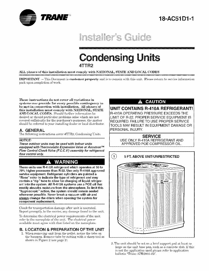
B. LOCATION & PREPARATION OFTHE UNiT1. When removing unit from the pallet, notice the tabs on
the basepan. Remove tabs by cutting with a sharp tool asshown in Figure 2 (see page 2).
UNIT CONTAINS R-410A REFRIGERANT!R-410A OPERATING PRESSURE EXCEEDS THE
LIMIT OF R-22. PROPER SERVICE EQUIPMENT IS
REQUIRED. FAILURE TO USE PROPER SERVICE
TOOLS MAY RESULT IN EQUIPMENT DAMAGE OR
PERSONAL INJURY.
SERVICEUSE ONLY R-410A REFRIGERANT ANDAPPROVED POE COMPRESSOR OIL.
5 FT. ABOVE UNIT-UNRESTRICTED©
2. The unit should be set on a level support pad at least aslarge as the unit base pan, such as a concrete slab. If thisis not the application used please refer to applicationbulletin "Trane APB2001-02".
|nsta||er's Guide
@ BASEPAN TAB REMOVAL
3. The support pad must NOT be in direct contact with anystructure. Unit must be positioned a minimum of 12"from any wall or surrounding shrubbery to insureadequate airflow. Clearance must be provided in front ofcontrol box (access panels) & any other side requiringservice access to meet National Electrical Code. Also,the unit location must be far enough away from anystructure to prevent excess roof run-off water frompouring directly on the unit. Do not locate unit(s) close tobedroom(s).
4. The top discharge area must be unrestricted for at leastfive (5) feet above the unit.
5. When the outdoor unit is mounted on a roof, be sure theroof will support the unit's weight. Properly selectedisolation is recommended to prevent sound or vibrationtransmission to the building structure.
6. The maximum length of refrigerant lines from outdoor toindoor unit should NOT exceed sixty (60) feet.
7. If outdoor unit is mounted above the air handler, maxi-mum lift should not exceed sixty (60) feet (suction line).If air handler is mounted above condensing unit, maxi-mum lift should not exceed sixty (60) feet (liquid line).
NOTE:Refer to "Refrigerant Piping Software" Pub. No. 32=3312=02.
8. Locate and install indoor coil or air handler in accor-dance with instruction included with that unit.
C. ACCUTRON TM FLOW CONTROL VALVEIf the indoor unit System Refrigerant Flow control is anAccutron TM orifice and check valve assembly, an orifice sizechange may be necessary.
The outdoor model determines the required orifice size.Check the listed orifice size on nameplate of the selectedoutdoor model. If the indoor unit is factory shipped with adiffhrent orifice size, the orifice must be changed to obtainsystem rated performance.
® BRAZE TYPE iNDOOR END
SEALING CAP
BODY .......
FIELD SUPPLIED_- LIQUID LINE
NOTE:Attach R-410A CAUTION Label (located in documentationpackage) to access panel of indoor section.
IMPORTANT:The outdoor unit is shipped with the proper size orifice and astick-on orifice size label in an envelope attached to the outdoorunit. Outdoor unit nameplate will have correct orifice sizespecified as BAYFCCV---A for rated performance.
D. iNSTALLING REFRIGERANT LINES
if using existing refrigerant lines make certain that all jointsare brazed, not soldered.
Condensing units have provisions for braze connections.
Pressure taps are provided on the service valves of outdoorunit for compressor suction and liquid pressures.
The indoor end of the recommended refrigerant line sets maybe straight or with a 90 degree bend, depending uponsituation requirements. This should be thoroughly checkedout before ordering refrigerant line sets.
The gas line must always be insulated.
in scroll compressor applications, dome temperatures maybe hot. Do not touch top of compressor, may cause minorto severe burning.
The units are factory charged with the system chargerequired when using fifteen (15) feet of connecting line. Unitnameplate charge is the same.
Final refrigerant charge adjustment is necessary. Usethe Charging Charts in the outdoor unit Service Facts.
1. Determine the most practical way to run the lines.
2. Consider types of bends to be made and space limitations.
NOTE:
Large diameter tubing will be very difficult to rebend once ithas been shaped.
3. Determine the best starting point for routing therefrigerant tubing- -INSIDE OR OUTSIDE THESTRUCTURE.
4,
5,
6.
7.
8,
Provide a pull-thru hole of sufficient size to allow bothliquid and gas lines.
Be sure the tubing is of sufficient length.
Uncoil the tubing ---do not kink or dent.
Route the tubing making all required bends andproperly secure the tubing before making connections.
To prevent a noise within the building structure due tovibration transmission from the refrigerant lines, thefollowing precautions should be taken:
a. When the refrigerant lines have to be fastened to floorjoists or other framing in a structure, use isolationtype hangers.
b. Isolation hangers should also be used -when refriger-ant lines are run in stud spaces or enclosed ceilings.
c. Where the refrigerant lines run through a wall or sill,they should be insulated and isolated.
d. Isolate the lines from all ductwork.
© 2001 American Standard inc. All Rights Reserved 18-AC51 D1-1
|nsta||er's Guide
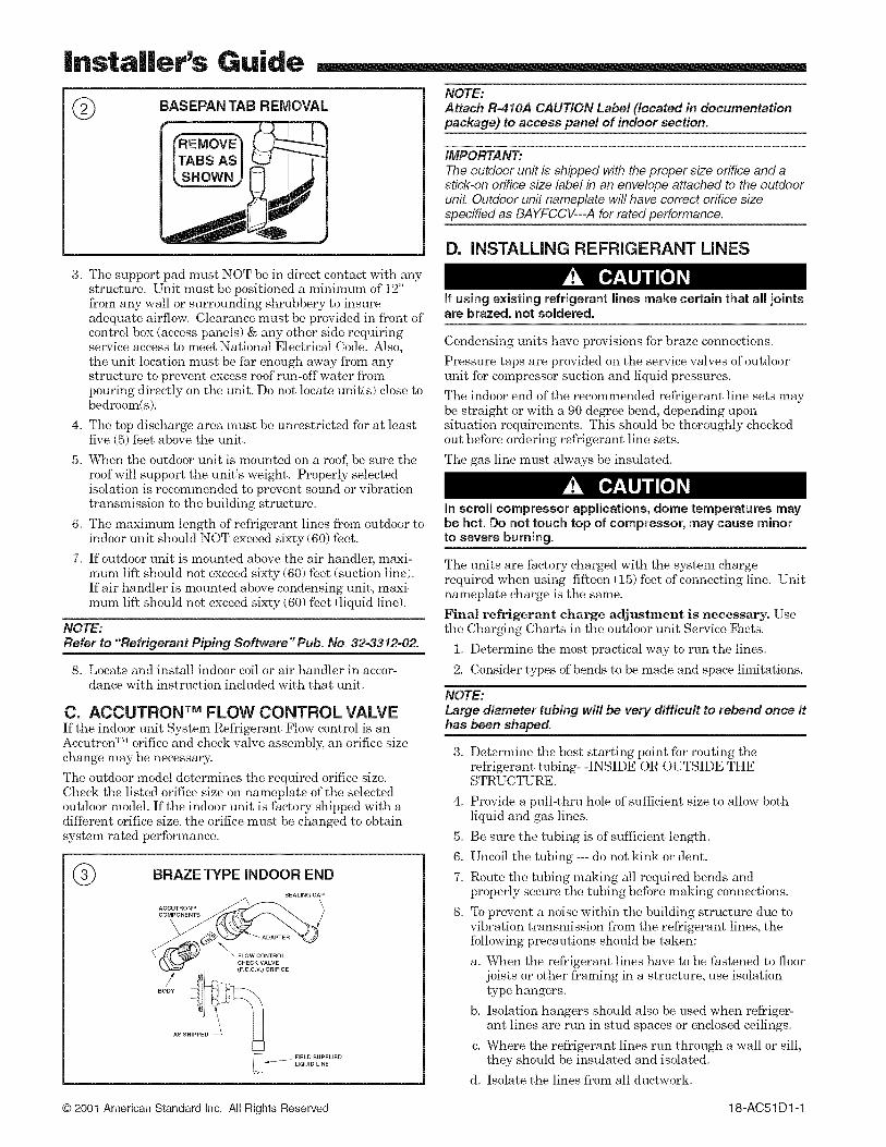
© LIQUID LINE SERVICE VALVEROLLED EDGE TO
J CAPTIVATE STEM
QCAP_ /
UNIT SIDE OF _ HEX HEADED
SE"V'Cg STEM
/LIQUID LINE
CONNECTION
E. SERVICE VALVE OPERATION
BRASS LIQUID LINE SERVICE VALVEThe Brass Liquid Line Service Valve is factory shipped in theseated position to hold factory charge. The pressure tapservice port (when depressed) opens only to the field brazingside of the valve when the valve is in the seated position.The liquid line valve is not a back seating valve (seeWARNING below).
Extreme caution should be exercised when opening theLiquid Line Service Valve. Turn valve stem counterclock=wise only until the stem contacts the rolled edge. (SeeFigure 4) No torque is required.
BRASS GAS LINE SERVICE VALVEThe Brass Gas Line Service Valve is shipped in the closedposition to hold the factory refrigerant charge. The pressuretap service port (when depressed) opens only to the fieldbrazing side when the valve is in the closed position. TheGas Line Service Valve is full open with a 1/4 turn. SeeFigure 5.
BRAZING REFRIGERANT LINES1. Remove lower access cover to access service valves.
2. Before brazing, remove plugs from external copper stubtubes. Clean internal and external surfaces of stub
tubes prior to brazing.
3. Cut and fit tubing, minimizing the use of sharp 90 ° bends.
4. Insulate the entire gas line and its fittings.
5. Do NOT allow uninsulated liquid line to come in directcontact with bare gas line.
6. Precautions should be taken to avoid heat damageto the pressure tap valve core during brazing. Itis recommended that the pressure tap port valvecore be removed and a wet rag wrapped aroundthe valve body.
NOTICE:
Use care to make sure that no moisture enters pressure tapport, while wet rag is being used.
NOTICE:
Precautions should be taken to avoid heat damage tobasepan during brazing. It is recommended to keep theflame directly off of the basepan.
7. Use a Dry Nitrogen Purge and Brazing Alloy without fluxwhen brazing the field line to the copper factory connec-tion. Flow dry nitrogen into either valve pressure tapport, thru the tubing and out the other port while brazing.
8. Braze using accepted good brazing techniques.
LEAK CHECK
IMPORTANT:Replace pressure tap port valve core before attaching hoses forevacuation.
After the brazing operation of refrigerant lines to both theoutdoor and indoor unit is completed, the field brazedconnections must be checked for leaks. Pressurize throughthe service valve ports, the indoor unit and field refrigerantlines with dry nitrogen to 350-400 psi. Use soap bubbles orother leak-checking methods to see that all field joints areleak-free! If not, release pressure; then repair!
SYSTEM EVACUATION
NOTE:Since the outdoor unit has a refrigerant charge, the gas andfiquid line valves must remain closed.
1. Upon completion of leak check, evacuate the refrigerantlines and indoor coil before opening the gas and liquidline valves.
2. Attach appropriate hoses from manifold gauge to gasand liquid line pressure taps.
NOTE:Unnecessary switching of hoses can be avoided andcomplete evacuation of all lines leading to sealed systemcan be accomplished with manifold center hose andconnecting branch hose to a cylinder of R=410A andvacuum pump.
3,
4.
Attach center hose of manifold gauges to vacuum pump.
Evacuate until the micron gauge reads no higher than350 microns.
5. Close off valve to vacuum pump and observe the microngauge. If gauge pressure rises above 500 microns in one (1)minute., then evacuation is incomplete, or system has a leak.
6. If vacuum gauge does not rise above 500 microns in one(1) minute, the evacuation should be complete.
7. With vacuum pump and micron gauge blanked off, openvalve on R-410A cylinder and charge refrigerant lines andindoor coil with vapor to tank pressure of R-410A supply.
NOTE:DO NOT VENT REFRIGERANT INTO THE ATMOSPHERE.
8. Close valve on R-410A supply cylinder. Close valves onmanifold gauge set and remove refrigerant charginghoses from liquid and gas pressure tap ports.
GAS LiNE SERVICE VALVEcap _ _-_ v4"ru_N ONLY
COUNTERCLOCKWISF_
4._ FO_FULLOP_:NPosrnoN
unit SIDE _ %s_ _:M
o_ w_v_:
PR_:SSUR_:TAPPO_
18-AC51 D1-1 3
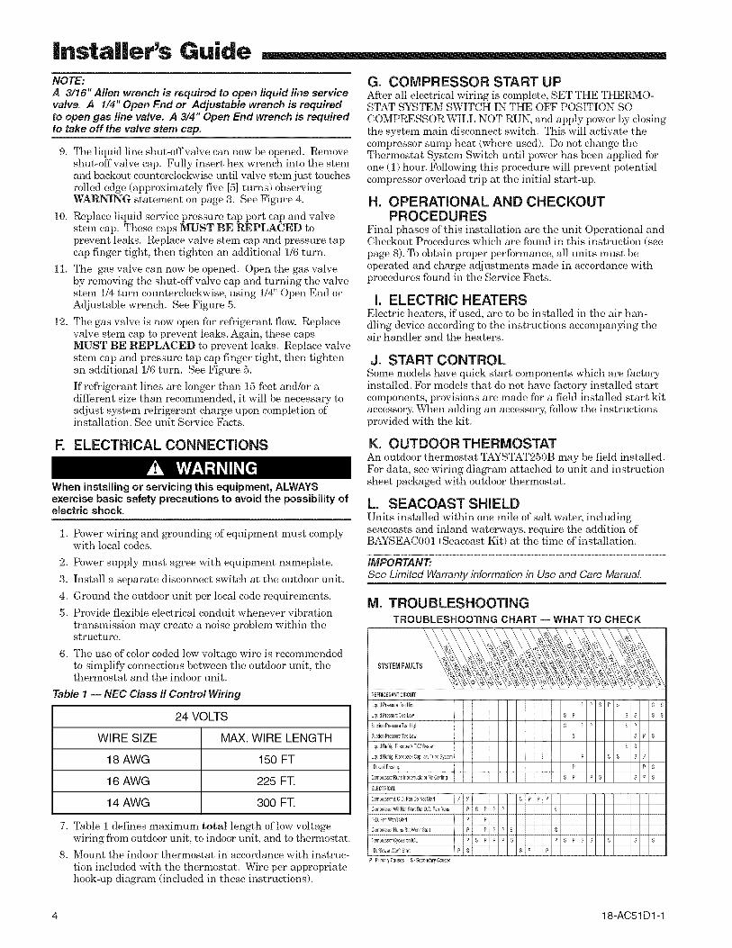
|nsta||er's GuideNOTE:A 3/16" Allen wrench is required to open liquid line servicevalve. A I/4" Open End or Adjustable wrench is requiredto open gas line valve. A 3/4" Open End wrench is requiredto take off the valve stem cap.
9. The liquid line shut-offvalve ean now be opened. Removeshut-off valve cap. Fully insert hex wrench into the stemand backout counte.rclockwise until valve stem just touchesrolled edge (approximately five [5] turns) observingWARNING statement on page 3. See Figure 4.
10. Replace liquid service pressure tap port cap and valvestem cap. These caps MIJST BE REPLACED toprevent leaks. Replace valve stem cap and pressure tapcap finger tight, then tighten an additional 1/6 turn.
11. The gas valve can now be opened. Open the gas valveby removing the shut-off valve cap and turning the valvestein 1/4 turn counterclockwise, using 1/4" Open End orAdjustable wrench. See Figure 5.
12. The gas valve is now open for refrigerant flow. Replacevalve stein cap to prevent leaks. Again, these capsMIDST BE REPLACED to prevent leaks. Replace valvestem cap and pressure tap cap finger tight, then tightenan additional 1/6 turn. See Figure 5.
If refrigerant lines are longer than 15 feet and/or adifihrent size than recommended, it will be necessary toadjust system refrigerant charge upon completion ofinstallation. See unit Service Facts.
F. ELECTRICAL CONNECTIONS
When installing or servicing this equipment, ALWAYSexercise basic safety precautions to avoid the possibility ofelectric shock.
1. Power -wiring and grounding of equipment must complywith local codes.
2. Power supply must agree with equipment nameplate.
3. Install a separate disconnect switch at the outdoor unit.
4. Ground the outdoor unit per local code requirements.
5. Provide flexible electrical conduit whenever vibrationtransmission may create a noise problem within thestrueture.
6. The use of color coded low voltage wire is recommendedto simplify connections between the outdoor unit, thethermostat and the indoor unit.
Table 1 -- NEC Class II Control Wiring
24 VOLTS
WIRE SIZE MAX. WIRE LENGTH
18 AWG 150 FT
16 AWG 225 FT.
14 AWG 300 FT.
7. Table 1 defines maximum total length of low voltagewiring from outdoor unit, to indoor unit, and to thermostat.
8. Mount the indoor thermostat in accordance with instruc-tion included with the thermostat. Wire per appropriatehook-up diagram (included in these instructions).
G. COMPRESSOR START UPAfter all electrical wiring is complete, SET THE THERMO-STAT SYSTEM SWITCH IN THE OFF POSITION SOCOMPRESSOR WILL NOT RUN, and apply power by closingthe system main disconnect switch. This will activate thecompressor sump heat (where used). Do not change theThermostat System Switch until power has been applied forone (1) hour. Following this procedure will prevent potentialcompressor overload trip at the initial start-up.
H. OPERATIONAL AND CHECKOUTPROCEDURES
Final phases of this installation are the unit Operational andCheckout Procedures which are found in this instruction (seepage 8). To obtain proper performance, all units must beoperated and charge adjustments made in accordance withprocedures found in the Service Facts.
I. ELECTRIC HEATERSElectric heaters, if used, are to be installed in the air han-dling device according to the instructions accompanying theair handler and the heaters.
J. START CONTROLSome models have quick start components which are factoryinstalled. For models that do not have factory installed startcomponents, provisions are made for a field installed start kitaccessory. When adding an accessory, follow the instructionsprovided with the kit.
K. OUTDOOR THERMOSTATAn outdoor thermostat TAYSTAT250B may be field installed.For data, see wiring diagram attached to unit and instructionsheet packaged with outdoor thermostat.
L. SEACOAST SHIELDUnits installed -within one mile of salt water, includingseacoasts and inland waterways, require the addition ofBAYSEAC001 (Seacoast Kit) at the time of installation.
IMPORTANT:See Limited Warranty information in Use and Care Manual
M. TROUBLESHOOTINGTROUBLESHOOTING CHART -- WHAT TO CHECK
SYSTEMFAULTS
REFRIGERANTCIRCUIT
ELECTRICAL
P- PNmaryCauses S-Sec0ndaryCauses
4 18-AC51 D1-1
|nsta||er's Guide
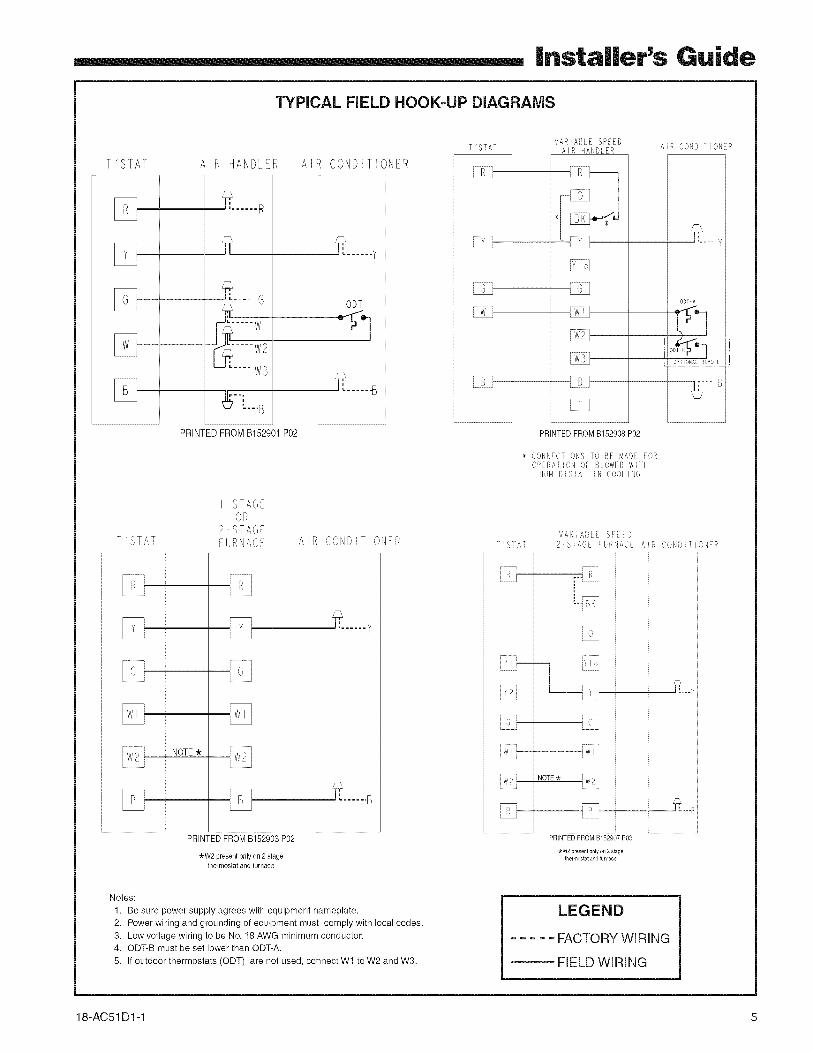
TYPICAL FIELD HOOK=UP DIAGRAMS
T 'STA1 A R tIANDL
/,--,,,
IT...... R
.... 6
_" .... Wl
I_ w2
PRINTEDFROMB152g01P02
AI CONDITIONER
/,--,,,
...... y
ODT
/" ,i?x
I-STAGEOR
2STAGET'STAT FURNACE AIR CQND!TIONER
NOTE
PRINTEDFROMB152903 P02
"kW2presentonlyon2stagethermostatandfurnace
VARIABLE SPEEDT'STAT AIR HANDLER AIR COI/Dli}ONER
'IL..y
ODI A
!L,o....
PRINTEDFROMB152908P02
CONNECTIONS TO BE MADE FOROPERA]ION OF BLOWER WlIH
HUMIDISTAT IN COOLING
I'D n 2 S ;.,G Lil'/_C Ai;i (01'} i101', R
, j Rr_ '! I
: J _ i,V? j NOTE* i ii_ [
PRINTED FROM B152907 P03
_rW2 present only on 2 stage
thermostat and furnace
Notes:
1. Be sure power supply agrees with equipment nameplate.
2. Power wiring and grounding of equipment must comply with local codes.
3. Low voltage wiring to be No. 18 AWG minimum conductor.4. ODT-B must be set lower than ODT-A.
,5. If outdoor thermostats (ODT) are not used, connect W1 to W2 and W3.
LEGEND
..... FACTORY WIRING
_ FIELD WIRING
18-AC51 D1-1 5
|nstal|er's Guide
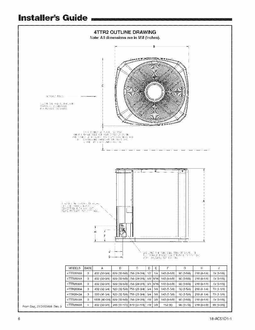
4TTR2 OUTLINE DRAWINGNote: All dimensions are in IVllVl(Inches).
SER', ,{i P,!'N L ................
EC RI¢,,L _Sl,D R RiGER_NI('or, I (=t,IJ_ ( J_R_ N( [iS
UNIT SHOULD BY PLACED SO ROOFRUN OFF WAIFR DOES NOI POUR DtRFCIiY ON UNIT,AND SiIOUID Bi[ A[ [EASF 305 (i2 _) FROM WAi{ AND
Ail SURROUNDINGSHrUBBerY ON TWO SIDLSOil{Eli iWO SiDFS UNF!FS;RJCIkD
J
Fi
X 6AS I I'JE Ig/ IUR! BAll S R'_ Ci ,',':L' , '}'
= D MAI ii';,; i)(:C,l'q ,',1 ('q /_' J/4 =' S,,[
ARE ?i;SSJR} ,'-P F Jq(
From Dwg. 21 D152898 Rev. 3
MODELS
4TTR2018A
4TTR2024A
4TTR2030A
4TTR2036A
4TTR2042A
4TTR2048A
4TTR2060A
BASE A B C D E F G
3 832 (32-3/4) 829 (32-5/8) 756 (29-3/4) 1/2 1/4 143 (5-5/8) 92 (3-5/8)
3 832 (32-3/4) 829 (32-5/8) 756 (29-3/4) 5/8 5/16 143 (5-5/8) 92 (3-5/8)
3 832 (32-3/4) 829 (32-5/8) 756 (29-3/4) 3/4 5/16 143 (5-5/8) 92 (3-5/8)
3 832 (32-3/4) 829 (32-5/8) 756 (29-3/4) 3/4 3/8 143 (5-5/8) 92 (3-5/8)
3 933 (36-3/4) 829 (32-5/8) 756 (29-3/4) 3/4 3/8 143 (5-5/8) 92 (3-5/8)
3 1035 (40-3/4) 829 (32-5/8) 756 (29-3/4) 7/8 3/8 143 (5-5/8) 92 (3-5/8)
4 832 (32-3/4) 946 (37-1/4) 870 (34-1/4) 7/8 3/8 152 (6) 98 (3-7/8)
H
210 (8-1/4)
210 (8-1/4)
210 (8-1/4)
210 (8-1/4)
210 (8-1/4)
210 (8-1/4)
219 (8-5/8)
J
79 (3-1/8)
79 (3-1/8)
79 (3-1/8)
79 (3-1/8)
79 (3-1/8)
79 (3-1/8)
86 (3-3/8)
6 18-AC51 D1-1
|nstal|er's Guide
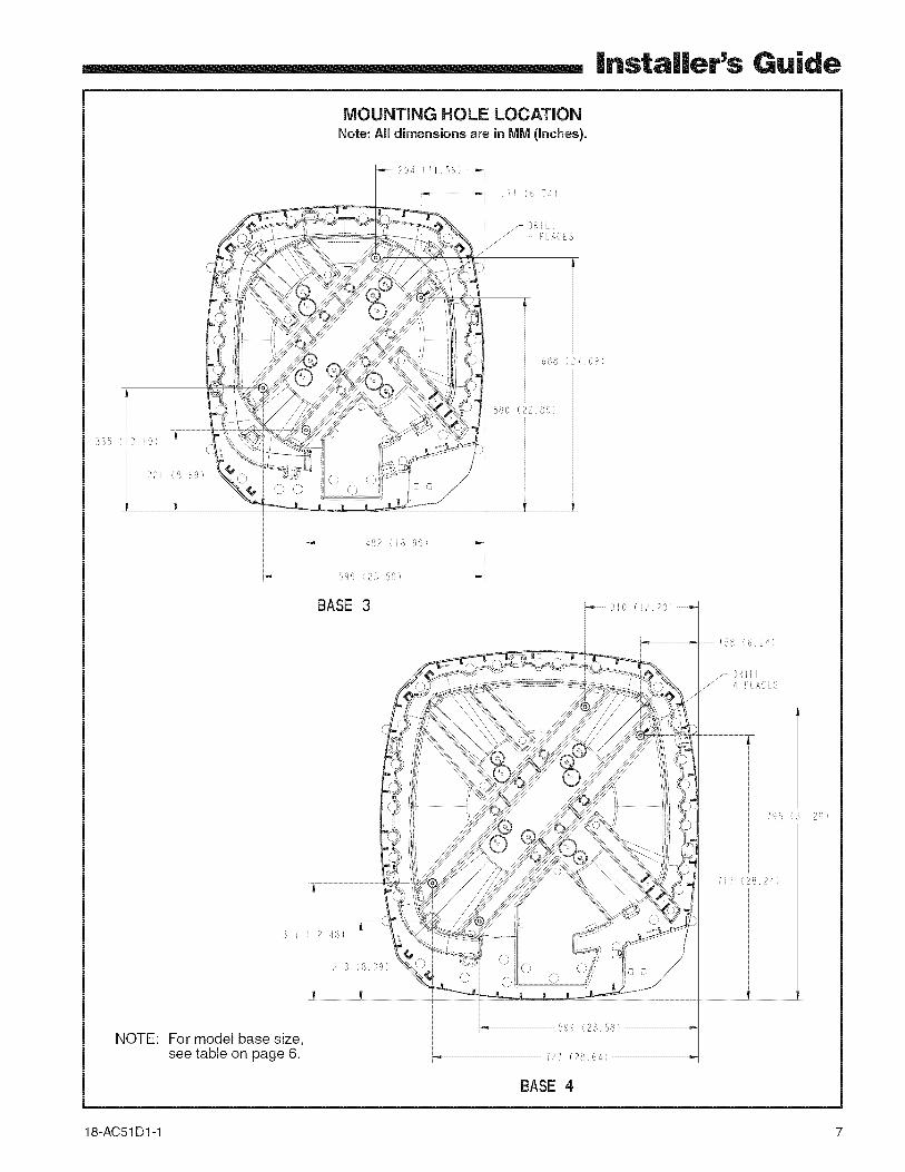
MOUNTING HOLE LOCATIONNote: All dimensions are in IVllVl(Inches).
NOTE:
462 (699)[
!i99 (23 f)_
BASE 3
,©,i
0 ,(}
For model base stze,see table on page 6.
BASE 4
18-AC51 D1-1 7
|nsta||er's GuideCHECKOUT PROCEDURE
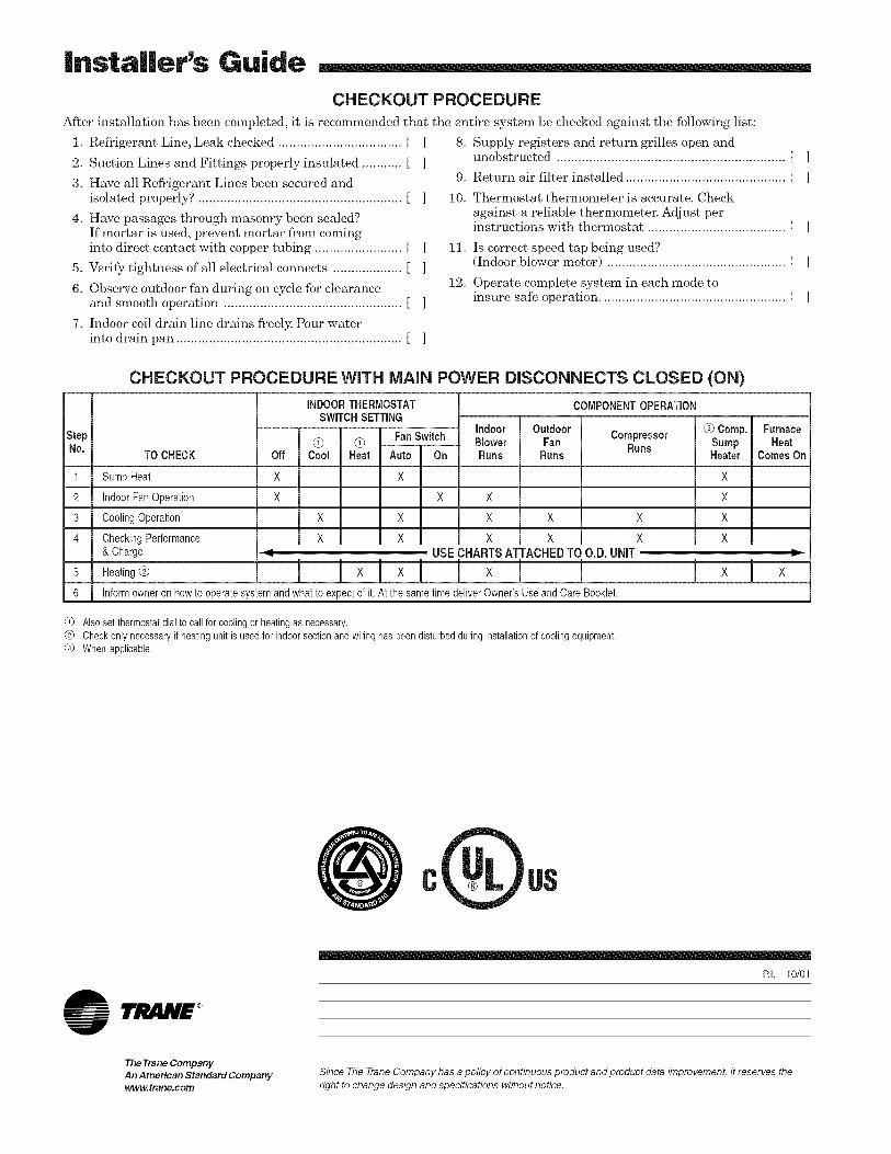
After installation has been completed, it is recommended that the entire system be checked against the following list:
1. Refrigerant Line, Leak checked .................................. [
2. Suction Lines and Fittings properly insulated ........... [
3. Have all Refrigerant Lines been secured andisolated properly? ........................................................ [
4. Have passages through masonry been sealed?If mortar is used, prevent mortar from coininginto direct contact with copper tubing ........................ [
5. Verify tightness of all electrical connects ................... [
6. Observe outdoor fan during on cycle for clearanceand smooth operation ................................................. [
]
]
]
]
8. Supply registers and return grilles open andunobstructed ............................................................... [ ]
9. Return air filter installed ............................................ [ ]
10. Thermostat thermometer is accurate. Checkagainst a reliable thermometer. Adjust perinstructions with thermostat ...................................... [ ]
11. Is correct speed tap being used?(Indoor blower motor) ................................................. [ ]
12. Operate complete system in each mode toinsure safe operation ................................................... [ ]
7. Indoor coil drain line drains freely. Pour waterinto drain pan .............................................................. [
CHECKOUT PROCEDUREWITH MAiN P(
StepNo. TO CHECK
1 Sump Heat
2 Indoor FanOperation
3 Cooling Operation
4 CheckingPerformance& Charge
5 Heating@
6
Off
iNDOOR THERMOSTATSWITCH SETTING
@ @ FanSwitchCool Heat Auto On
X X
x x
Ix Ix
I
)WER DISCONNECTS CLOSED (ON)
COMPONENTOPERATION
Compressor @ Comp. FurnaceRuns Sump Heat
Heater Comes On
Indoor OutdoorBlower FanRuns Runs
x x
x x x
I x I x xUSECHARTSATTACHEDTOO.D. UNiT
Ix!×l ! × I I Ix IxInformowneron howto operatesystemandwhat to expectof it. At the sametime deliverOwner'sUseand CareBooklet.
X
X
X
X
It,
@ Also set thermostat dial to call for cooling or heating as necessary.
@ Check only necessary if heating unit is used for indoor section and wiring has been disturbed during installation of cooling equipment.
@ When applicable.
C
RI. 10/01
1rJMN'£
The Trane Company
An American Standard Companywww.trane.com
Since The Trane Company has a policy of continuous product and product data improvement, it reserves the
right to change design and specifications without notice.


![Alpha Condensing[1]](https://img.pdfslide.us/doc/110x75/552d860c4a7959035a8b4755/alpha-condensing1.jpg)