Embed Size (px)
Citation preview

GR
Condensed Instructions
IFC 010 CIFC 010 WSignal converters for OPTIFLUX flowmeters
Variable area flowmeters
Vortex flowmeters
Flow controllers
Electromagnetic flowmeters
Ultrasonic flowmeters
Mass flowmeters
Level measuring instruments
Communications technology
Engineering systems & solutions
Switches, counters, displays and recorders
Heat metering
Pressure and temperature
© KROHNE 08/2004 7.02140.35.00
Subject to change without notice.
Applicable toSoftware-Versions
IFC 010 _ / DDisplay versionNo. 806325.07andNo. 317551.02and higher
IFC 010 _ / BBasic versionoperator-controllableHHT 010No. 806323.06and higher
PLEASE NOTEThese concise instructions do not include the following: device description,technical data, standards, approvals, etc., nor conditions pertaining to product liability and warranty.The operator is, however, obligated to take note of these sections in thedetailed Installation and Operating Instructions.

2 IFC 010
Contents
1 Electrical connection: power supply.............................................................................................................................................3 1.1 Important installation notes ...............................................................................................................................................................3 1.1.1 Location.............................................................................................................................................................................................3 1.1.2 Only for separate systems/signal converters (W versions) ..............................................................................................................3 1.1.3 Cable entries .....................................................................................................................................................................................3 1.2 Connection to power .........................................................................................................................................................................4 1.3 Electrical connection of separate flow sensor (W Versions) ............................................................................................................5 1.3.1 General information on signal cable A and field current cable C ......................................................................................................5 1.3.2 Grounding of flow sensor ..................................................................................................................................................................5 1.3.3 Cable preparation..............................................................................................................................................................................5 1.3.4 Cable lengths (max. distance between signal converter and flow sensor)........................................................................................6 1.3.5 Connection diagrams I and II (power supply, converter and flow sensor)........................................................................................7
2 Electrical connection of outputs...................................................................................................................................................8 2.1 Current output I .................................................................................................................................................................................8 2.2 Pulse output P and status output S ...................................................................................................................................................8 2.3 Connection diagrams for outputs ......................................................................................................................................................9
3 Start-up...........................................................................................................................................................................................10 3.1 Powering up and measurement ......................................................................................................................................................10 3.2 Factory settings ...............................................................................................................................................................................10
4 Operation of the signal converter................................................................................................................................................12 4.1 Operating concept ...........................................................................................................................................................................12 4.2 Table of settable functions ..............................................................................................................................................................13 4.3 Error messages in measuring mode ...............................................................................................................................................16 Return a device for testing or repair to KROHNE...................................................................................................................................19

IFC 010 3
1 Electrical connection: power supply 1.1 Important installation notes
1.1.1 Location Electrical connection in accordance with VDE 0100 ”Regulations governing heavy-current installations with
line voltages up to 1000 V” or equivalent national regulations. Do not cross or loop cables inside the terminal compartment. Use separate cable entries (see below) for power supply, field current cables, signal lines, outputs and inputs. Protect flowmeters or switchgear cabinets with built-in devices from direct sunlight. Fit a sunshade if necessary. When installed in cabinets, signal converters must be adequately cooled, e.g. use fans or heat exchangers. Do not expose signal converters to intense vibration.
1.1.2 Only for separate systems/signal converters (W versions)
Keep distance between flow sensor and signal converter as short as possible. See Sect. 1.3.4 for maximum permissible length of signal and field current cables.
Use the supplied KROHNE signal cable A (Type DS), standard length 5 m (16 ft).
Always calibrate flow sensor and signal converter together. Therefore, when installing, ensure primary constant GKL is identical; see instrument nameplate for the flow sensor. If the GKL is not identical, set the signal converter to the GKL of the flow sensor. Refer also to Sections 4.
1.1.3 Cable entries
NOTE: Ensure gaskets are fitted correctly and maintain the following max. torques!
1 Max. torques for M 20, 1/2" NPT or 1/2" PF adapters: 4 Nm / 2.8 ft × lbf 2 Max. torques for M 20 only: 3 Nm / 2.1 ft × lbf 3 Gasket
A) M 20 cable entries These cable entries may only be used for flexible electrical cables if the relevant electrical regulations so allow,
e.g. National Electric Code (NEC). Do not fix rigid metal conduits (IMC) or flexible plastic conduits to the M 20 cable entries, refer to “Point B, C” below (1/2” NPT or PF adapters).
B) ½" NPT adapters C) ½" PF adapters For most North American systems the regulations require that electrical conductors be laid in conduits,
particularly for power voltages > 100 V AC. In such cases, use the 1/2" NPT or 1/2" PF adapters to which flexible plastic conduits can be screwed. Do not use rigid metal conduits (IMC)! Lay conduits such that no moisture can penetrate into the converter housing. Should there be risk of any condensation water forming, inside cross-section of the conduit around the cables at these adapters with a suitable sealing compound.
3
1
2

4 IFC 010
1.2 Connection to power
Rated values: The flowmeter housings protecting the electronic equipment from dust and moisture must always be kept closed. The selected creepage distances and clearances have been sized in conformity with VDE 0110 and IEC 664 for contamination category 2. Supply circuits and output circuits are designed to meet the standards of overvoltage classes III and II, respectively.
Safety isolation: the flowmeters (signal converters) must be provided with an isolating facility. 1. AC Version 2. AC Version 230/240 V AC (200 - 260 V AC)
switchable to 115/120 V AC (100 - 130 V AC)
200 V AC (170 - 220 V AC) switchable to 100 V AC (85 - 110 V AC)
Note information on instrument nameplate: supply voltage and frequency The PE protective ground conductor for the power supply must be connected to the separate U-clamp
terminal in the terminal compartment of the signal converter. For exceptions (compact systems), refer to installation instructions for the flow sensor.
Connection diagrams I and II for electrical connection between flow sensor and signal converter: refer to
Section 1.3.5. 3. AC Version DC Version 48 V AC (41 - 53 V AC)
switchable to 24 V AC (20 - 26 V AC)
24 V DC (11-32 V DC)
Note information on instrument nameplate: supply voltage and frequency. For measurement reasons, connect an FE functional ground conductor to the separate U-clamp terminal in the
terminal compartment of the signal converter. If connected to a functional extra-low voltage source (24 V AC / DC, 48 V AC), provide for protective separation
(PELV) in conformity with VDE 0100 / VDE 0106 or IEC 364 / IEC 536, or equivalent national regulations. Connection diagrams I and II for power supply and electrical connection between flow sensor and signal
converter: refer to Section 1.3.5. Connection to power Power fuse F1 Power U-clamp terminal
AC: 100 – 240 V L N PE protective conductor AC: 24 / 48 V 1L~ 0L~ FE DC: 24 V L+ L– FE
functional ground
for internal use only
Warning: Instrument must be properly grounded to avoid electrical shock.

IFC 010 5
1.3 Electrical connection of separate flow sensor (W Versions)
1.3.1 General information on signal cable A and field current cable C
Use of the KROHNE shielded signal cable type DS with foil screen and magnetic shield will ensure proper operation of the equipment.
Signal cable to be permanently laid. Connect shields via stranded drain wires. Underwater and underground installation possible. Insulating material is flame-retardant to IEC IEC 332.1 / VDE 0742. Signal cables are low in halogen, unplasticized, and stay flexible at low temperatures.
Signal cable Type DS, with double shielding 1 Stranded drain wire, 1st shield, 1.5 mm2 or AWG14 2 Insulation 3 Conductor 0.5 mm2 or AWG 20 (3.1 red / 3.2 white) 4 Special foil, 1st shield 5 Inner sheath 6 Mu-metal foil, 2nd shield 7 Stranded drain wire, 2nd shield, 0.5 mm2 or AWG 20 8 Outer sheath Field current cable C with single shielding Cross-section is dependent on required length of cable, see Table in Sect. 1.3.4. 1.3.2 Grounding of flow sensor All flowmeters must be properly grounded.
The grounding conductor should not transmit any interference voltages. Do not ground any other electrical device together with this conductor. The flow sensor is connected to ground by means of an FE functional ground conductor. Special information on grounding various flow sensors is contained in the separate installation instructions for flow sensors. These instructions also contain detailed descriptions on how to use grounding rings and how to install flow sensors in metal or plastic pipes or internally coated pipelines.
1.3.3 Cable preparation Customer-supplied materials W Insulation tubing (PVC), Ø 2.0-2.5 mm (dia. 1") X Heat-shrinkable tubing or cable sleeve Y Wire end sleeve to DIN 41 228: E 1.5-8 Z Wire end sleeve to DIN 41 228: E 0.5-8 Preparation for connection to flow sensor Length Ferrule mm inch a 55 2.17 b 10 0.39 c 15 0.59 d 8 0.30
DS signal cable bending radius ≥ 50 mm (≥ 2")

6 IFC 010
Preparation for connection to IFC 010 W signal converter Length Ferrule mm inch a 90 3.60 b 8 0.30 c 25 1.00 d 8 0.30 External shielding of DS signal cable Wrap stranded drain wire (7) around the metal foil and clamp under the shield terminal in the signal converter
terminal box. 1.3.4 Cable lengths (max. distance between signal converter and flow sensor)
Abbreviations and explanatory notes used in the following tables, diagrams and connection diagrams
C Field current cable C, with single shielding, type and length see Table D High-temperature silicone cable, 3 × 1.5 mm2 (14 AWG) Cu, with single shielding, max. length 5 m (16 ft) E High-temperature silicone cable, 2 × 1.5 mm2 (14 AWG) Cu, max. length 5 m (16 ft) L Cable length CB Intermediate connection box required in connection with cables D and E for flow sensors OPTIFLUX 4000 F, 5000 F and 6000 F in cases where process temperatures exceed 150 °C (302 °F)
Recommended length of signal cable for magnetic field frequency ≤ 1/6 × power frequency Flow sensor Meter size Signal cable DN mm inch OPTIFLUX 1000 F 10 – 15 3/8 – 1/2 DS A4 25 – 150 1 – 6 DS A3 AQUAFLUX F 10 – 1000 3/8 – 40 DS A1 OPTIFLUX 4000 F 10 – 150 3/8 – 6 DS A2 200 – 1000 8 – 40 DS A1 OPTIFLUX 5000 F 4.5 – 15 1/8 – 1/2 DS A4 25 – 100 1 – 4 DS A2 OPTIFLUX 6000 F 10 – 15 1/8 – 1/2 DS A4 25 – 80 1 – 3 DS A4
Field current cable C: max. length and min. cross-section Length Type of cable, single shielding 0 - 150 m 5 - 500 ft 2 × 0.75 mm2 Cu / 2 × 18 AWG 150 - 300 m 500 - 1000 ft 2 × 1.50 mm2 Cu / 2 × 14 AWG
Warning: Instrument must be properly grounded to avoid electrical shock.
DS signal cable bending radius ≥ 50 mm (≥ 2")
Cable length
Cable length
Electrical conductivity of process liquid Electrical conductivity of process liquid
DS1
DS2
DS3
DS4
DS1
DS2
DS3
DS4

IFC 010 7
1.3.5 Connection diagrams I and II (power supply, converter and flow sensor)
The figures in brackets indicate the stranded drain wires for the shields, as shown in cross-sectional drawing of signal cable.
Electrical connection to VDE 0100 “Regulations governing heavy-current installations with line voltages up to 1000 V” or equivalent national regulations.
Power supply 24 V AC / DC: functional extra-low voltage with protective separation in conformity with
VDE 0100, Part 410 or equivalent national regulations. FE = functional ground conductor
I Process temperature < 150°C / 302°F II Process temperature > 150°C / 302°F IFC 010 W IFC 010 W
Flow sensors Flow sensors
DS DS
CB

8 IFC 010
Connection of shields to the IFC 010 1 DS Signal cable 2 Shield terminal for shielded signal cable 3 Field power cable 4 Shield terminal for shielded field power cable 5 Housing wall, signal converter 6 Cable entries 2 Electrical connection of outputs
2.1 Current output I • The current output is galvanically isolated from all input and output circuits. • Typical current output
approx. 15 V DC positive voltage of current output current sink chassis ground, current output
• The current output can also be used as an internal voltage source for the outputs. Uint = 15 V DC I = 23 mA when operated without receiver instruments at the current output I = 3 mA when operated with receiver instruments at the current output • Connection diagrams, see Sect. 2.3. 2.2 Pulse output P and status output S
• The pulse and status outputs are galvanically isolated from the current output and all input circuits.
• Typical pulse and status outputs B1 S status output P ⊥ chassis ground P pulse output • The pulse and status outputs can be operated in the active or passive mode. Active mode: The current output is the internal voltage source, connection of electronic totalizers Passive mode: External DC or AC voltage source required, connection of electronic or
electromechanical totalizers Digital pulse division, interpulse period is non-uniform. Therefore, if frequency meters or cycle counters are
connected, allow for minimum counting interval: 10.000 gate time, counter ≤ P100% [ Hz ]

IFC 010 9
2.3 Connection diagrams for outputs DC voltage, external power source (Uext), note connection polarity
External voltage source (Uext), DC or AC voltage, connection polarity arbitrary
Current output Current output Iactive Ipassive Active mode
The current output supplies the power for operation of the outputs.
Passive mode
External power source required for operation of the outputs.
I = 0/4 - 20 mA I = 0/4 - 20 mA Uext 15...20 V DC 20...32 V DC Ri ≤ 500 Ω Ri 0...500 Ω 250...750 Ω Pulse output Ppassive Pulse output Pactive for electronic or (and current output Iactive) for electronic (EC) totalizers with and electromechanical without current output I totalizers
Uext ≤ 32 V DC/ ≤ 24 V AC Uint ≤ 15 V DC from current output Imax ≤ 150 mA Operation with current output: (incl. status output) Imax ≤ 3 mA Operation without current output: Imax ≤ 23 mA 15 V R ≤ Imax Status output Spassive Status output Sactive with and without current output I Uint ≤ 15 V DC from current output Imax ≤ 3 mA Operation with current output Imax ≤ 23 mA Operation with current output Uext ≤ 32 V DC/ ≤ 24 V AC Imax ≤ 150 mA (incl. status output)
Uext
Uext
Load Load

10 IFC 010
3 Start-up 3.1 Powering up and measurement
The flowmeter is delivered ready for use. All operating data have been factory set in accordance with your specifications.
Power the unit, and the flowmeter will immediately start process flow measurement. Basic version, signal converter IFC 010 _ / B A light emitting diode (LED) under the cover of the electronic section shows the measurement status. LED flashing . . . green: measurement correct, everything all right. green / red: momentary overdriving of outputs and/or A/D converter. red: fatal error, parameter error or hardware fault, please consult factory. Display version, signal converter IFC 010 _ / D When powered, the display shows in succession: START UP and READY.
This is followed by display of the current flow rate and/or the current totalizer count on either a continuous or alternating basis, depending on the setting under Fct. 1.04.
3.2 Factory settings All operating data are factory set according to your order specifications. If you have not made any particular specifications at the time of ordering, the instruments will be delivered with
the standard parameters and functions listed in the Table below. To facilitate easy and rapid initial start-up, current output and pulse output are set to process flow measurement
in “2 flow directions”, so that the current flowrate is displayed and the volumetric flow counted independent of the flow direction. On instruments equipped with a display, measured values may possibly be shown with a “ – ” sign.
This factory setting for the current and pulse outputs may possibly lead to measuring errors, particularly in the
case of volume flow counting: For example, if pumps are switched off and a “backflow” occurs which is not within the range of the low-flow
cutoff, or if separate displays and counts are required for both flow directions. To avoid faulty measurements, it may therefore, be necessary to change the factory settings of some or all of the
following functions: – low-flow cutoff, Fct. 1.03 – current output I, Fct. 1.05 – pulse output P, Fct. 1.06 – display (option), Fct. 1.04

IFC 010 11
Standard factory settings Function Setting 1.01 Full-scale range Q100% see nameplate 1.02 Time constant 3 s, for I, S and display 1.03 Low-flow ON: 1 % cutoff OFF: 2 % 1.04 Display (option) flow rate m3/hr or US Gal/min Totalizer(s) m3 or US Gal 1.05 Current output I function 2 directions range 4 – 20 mA error message 22 mA 1.06 Pulse output P function 2 directions pulse value 1 pulse/s pulse width 50 ms 1.07 Status output P Flow direction 3.01 Language for display only English 3.02 Flowmeter diameter see nameplate flow direction (see arrow on flow sensor) + direction 3.04 Entry code no 3.05 User unit Liter/hr or US Mgal/day

12 IFC 010
Part B IFC 010 _ / D Signal converter 4 Operation of the signal converter
4.1 Operating concept
1 3 6. 4 9 m 3 / h r
Measuring mode
CodE 1 - - - - - - - - - - - - -
When this display appears, press following keys: → → → ↵ ↵ ↵ ↑ ↑ ↑
Menu column Function column Data column
3.00 INSTALL.
2.00 TEST
1.00 OPERATION
Direction of movement
See Handbook Sect. 4.4
3.05 USER UNIT
3.04 ENTRY CODE
3.03 ZERO SET
3.02 FLOWMETER
3.01 LANGUAGE
2.02 HARDW. INFO
2.01 TEST Q
1.07 IND. OUTP. S
1.06 PULS. OUTP. P
1.05 CUR. OUTP. I
1.04 DISPLAY
1.03 L.F. CUTOFF
1.02 TIMECONST.
1.01 FULL SCALE

IFC 010 13
4.2 Table of settable functions Function Text Description and settings 1.00 OPERATION Operations menu 1.01 FULL SCALE Full-scale range for flowrate Q100% Select unit • m3/hr • Liter/Sec • US.Gal/min • user unit, factory set is “Liter/hr” or “US MGal/day” (see Fct. 3.05) Press → key to transfer to number setting. Setting ranges The ranges are dependent on the meter size (DN) and the flow velocity (v): Qmin = DN2 x vmin Qmax = DN2 x vmax Nom. dia./meter size vmin = 0,3 m/s vmax = 12 m/s (1 ft/s) (40 ft/s) • DN 2.5–1000 / 1/10”–40”: 0.0053 – 33 900 m3/hr 0.0237 – 152 000 US.Gal/min → VALUE P Pulse value (Fct. 1.06 “VALUE P”) has been changed. 1.02 TIMECONST. Time constant Select: • ALL
(applies to display and all outputs) • ONLY I+S
(only display, current and status outputs) Range: • 0.2 – 99.9 Sec 1.03 L.F.CUTOFF Low-flow cutoff (SMU) • OFF (fixed trip points: ON = 0.1% / OFF = 0.2%
for 100 and 1000 Hz, see Fct. 1.06, 1% or 2%) • PERCENT (variable values) ON OFF
1 – 19% 2 – 20% Note:
Cutoff “off” value must be greater than cutoff “on” value. Press ↵ key to return to Fct. 1.03 L.F. CUTOFF. 1.04 DISPLAY Display functions → DISP.FLOW Select flow display • NO DISP. • user unit, factory set is “Liter/hr” or “US MGal/day (see Fct. 3.05) • m3/hr • PERCENT • Liter/Sec • BARGRAPH (value and bargraph display in %) • US.Gal/min → DISP.TOTAL. Select totalizer display • NO DISP. (totalizer switched on but not displayed) • OFF (totalizer switched off) • +TOTAL. • –TOTAL. • +/–TOTAL. • SUM (Σ) • ALL (displaysingle counts or all) • m3 • Liter • US.Gal • user unit, factory set is “Liter” or “US MGal” (see Fct. 3.05). Press → key to transfer to format setting. Format setting • Auto (exponent notation) • # . ####### • ##### . ### • ## . ###### • ###### . ## • ### . ##### • ####### . # • #### . #### • ######## → DISP.MSG. Additional messages required in measuring mode? • NO • YES (cyclic change with displays of measured values) Press ↵ key to return to Fct. 1.04 DISPLAY.
π 4
π 4

14 IFC 010
Function Text Description and settings 1.05 CURRENT I Current output I → FUNCT. I Select function for current output I • OFF (switched off) • 1 DIR. (1 flow direction) • 2 DIR. (forward/reverse flow, F/R flow measurement) → RANGE I Select measuring range • 0 - 20 mA • 4 - 20 mA (fixed ranges) → I ERROR Select error value • 0 mA • 3.6 mA (only with range 4-20 mA) • 22 mA 1.06 PULS.OUTP. P Pulse output P → FUNCTION P Select function for pulse output P • OFF (switched off) • 1 DIR. (1 flow direction) • 2 DIR. (forward/reverse flow, F/R measurement) → SELECT P Select pulse type • 100 Hz • PULSE/VOL. (pulses per unit volume, flow rate) • 1000 Hz • PULSE/TIME (pulses per unit time for 100% flowrate) → PULSWIDTH Select pulse width • 50 mSec • 100 mSec • 200 mSec • 500 mSec • 1 Sec → VALUE P Set pulse value per unit volume (appears only when “PULSE/VOL.“ has been set under “SELECT P“) • xxxx PulS/m3 • xxxx PulS/Liter • xxxx PulS/US.Gal • xxxx PulS/ user unit, factory set is “Liter“ or “US MGal“ (see Fct. 3.05). → VALUE P Set pulse value per unit time (appears only when „PULSE/TIME“ has been set under „SELECT P“). • xxxx PulS/Sec (=Hz) • xxxx PulS/min • xxxx PulS/hr • xxxx PulS/user unit, factory set is “hr” or “day” (see Fct. 3.05) 1.07 IND. OUTP. S Status output S • ALL ERROR • FATAL ERROR • OFF • ON • F/R INDIC. (F/R indication for forward/reverse measurement) • TRIP. POINT Setting range: 002 - 115 PERCENT • EMPTY PIPE (appears only when this option is installed) 2.00 TEST Test menu 2.01 TEST Q Test measuring range Q Precautionary query • SURE NO Press ↵ key to return to Fct. 2.01 “TEST Q”. • SURE YES Press ↵ key, then use ↑ or ↓ key to select value: -110 / -100 / -50 / -10 / 0 / +10 / +50 / +100 / +110 PCT. 2.02 HARDW. INFO Hardware information and error status Before consulting factory, please note down all 6 codes. → MODUL ADC X . X X X X X . X X Y Y Y Y Y Y Y Y Y Y → MODUL IO X . X X X X X . X X Y Y Y Y Y Y Y Y Y Y → MODUL DISP. X . X X X X X . X X Y Y Y Y Y Y Y Y Y Y

IFC 010 15
Function Text Description and settings 3.00 INSTALL. Installation menu 3.01 LANGUAGE Select language for display texts • GB / USA (English) • F (French) • D (German) • others on request 3.02 FLOWMETER Set data for flow sensor → DIAMETER Select size from meter size table • DN 10 - 1000 mm or 3/8 - 40 inch → FULL SCALE Full-scale range for flow Q100% To set, refer to Fct. 1.01 “FULL SCALE” above. → VALUE P Pulse value (Fct. 1.06 “VALUE P”) has been changed. → GKL VALUE Set primary constant GKL see flow sensor typeplate. Range: • 1.0000 - 9.9999 → FIELD FREQ. Magnetic field frequency Values: 1/6 or 1/18 of power frequency, see typeplate. → LINE FREQ. Normal line frequency in your country Please note:
This function is only provided for units with DC power supply to suppress line-frequency interference.
Values: 50 Hz and 60 Hz → FLOW DIR. Define flow direction (in F/R mode: forward flow). Set according to direction of arrow on flow meter: • + DIR. • – DIR. 3.03 ZERO SET Zero calibration Note:
Carry out only at “0” flow and with completely filled measuring tube! Precautionary query • CALIB. NO • CALIB. YES • STORE NO • STORE YES 3.04 ENTRY CODE Entry code required to enter setting mode? • NO (= entry with → only) • YES (= entry with → and Code 1: → → → ↵ ↵ ↵ ↑ ↑ ↑) 3.05 USER UNIT Set any required unit for flowrate and counting → TEXT VOL. Set text for required flowrate unit (max. 5 characters) Factory-set: “Liter” or “MGal”. Characters assignable to each place: • A-Z, a-z, 0-9, or “ – ” (= blank character). → FACT. VOL. Set conversion factor (FM) for volume Factory set “1.00000” for “Liter” or “2.64172E-4” for “US MGal” (exponent notation, here: 1 x 10³ or 2.64172 x 10⁻⁴). Factor FM = volume per 1m3. Setting range • 1.00000 E-9 to 9.99999 E+9 (= 10-9 to 10+9) → TEXT TIME Set text for required time unit (max. 3 characters) Factory-set: “hr” or “day”: Characters assignable to each place: • A-Z, a-z, 0-9, or “ – ” (= blank character). → FACT. TIME Set conversion factor (FT) for time Factory-set: “3.60000 E+3” for “hour” or “8.64000 E+4” for “day” (exponent notation, here: 3.6 x 10³ or 8.64 x 10⁻⁴). Set factor FT in seconds. Setting range • 1.00000 E-9 to 9.99999 E+9 (= 10-9 to 10+9) 3.06 APPLICAT. Set overload point for A/D converter → EMPTY PIPE Switch on “empty tube” identifier option? (appears only when this option is installed) • YES • NO

16 IFC 010
4.3 Error messages in measuring mode
The following list gives all errors that can occur during process flow measurement. Errors shown in display when “YES” set in Fct. 1.04 DISPLAY, subfunction “DISP. MSG.”
Error messages Description of error Error clearance LINE INT. Power failure
Note: no counting during power failure Cancel error in RESET/QUIT. Menu Reset totalizer if necessary.
CUR. OUTP. I Current output overranged. Check and if necessary correct instrument parameters. After elimination of cause, error message deleted automatically.
PULSOUTP. P Pulse output overranged. Note: totalizer deviation possible.
Check and if necessary correct instrument parameters. After elimination of cause, error message deletes automatically.
ADC Analog / digital converter overranged
Error message deletes automatically after elimination of cause.
FATAL. ERROR Fatal error, all outputs set to “min. values” Please consult factory. TOTALIZER Totalizer has been reset Cancel error message in
RESET/QUIT menu. EMPTY PIPE Pipe has run dry. Message appears only
when the “empty pipe identifier” option is installed and the function is activated under Fct. 3.06 APPLICAT., submenu “EMPTY PIPE”.
Fill pipe.

IFC 010 17
Notes

18 IFC 010
Notes
IFC 010 19
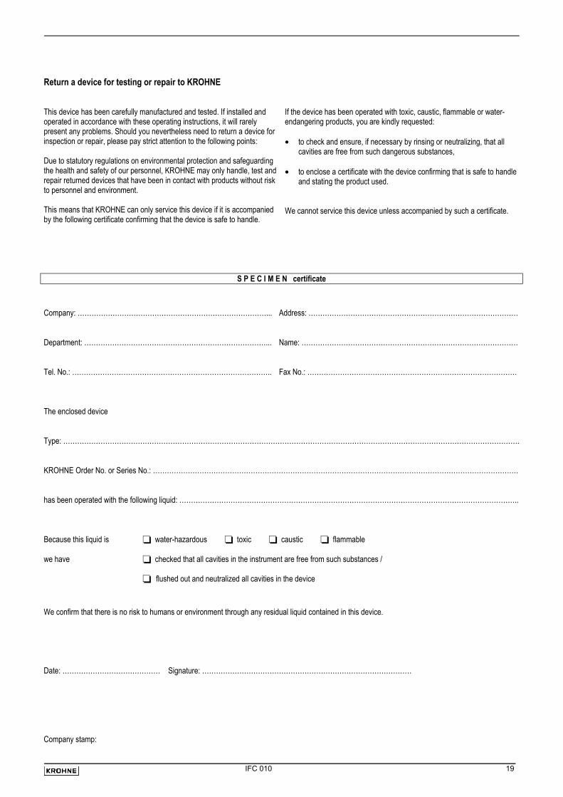
Return a device for testing or repair to KROHNE This device has been carefully manufactured and tested. If installed and operated in accordance with these operating instructions, it will rarely present any problems. Should you nevertheless need to return a device for inspection or repair, please pay strict attention to the following points: Due to statutory regulations on environmental protection and safeguarding the health and safety of our personnel, KROHNE may only handle, test and repair returned devices that have been in contact with products without risk to personnel and environment. This means that KROHNE can only service this device if it is accompanied by the following certificate confirming that the device is safe to handle.
If the device has been operated with toxic, caustic, flammable or water-endangering products, you are kindly requested: • to check and ensure, if necessary by rinsing or neutralizing, that all
cavities are free from such dangerous substances,
• to enclose a certificate with the device confirming that is safe to handle and stating the product used.
We cannot service this device unless accompanied by such a certificate.
S P E C I M E N certificate
Company: ………………………………………………………………………... Address: ………………………………………………………………………………
Department: ……………………………………………………………………... Name: …………………………………………………………………………………
Tel. No.: ………………………………………………………………………….. Fax No.: ………………………………………………………………………………
The enclosed device
Type: …………………………………………………………………………………………………………………………………………………………………………….
KROHNE Order No. or Series No.: ………………………………………………………………………………………………………………………………………….
has been operated with the following liquid: ………………………………………………………………………………………………………………………………..
Because this liquid is water-hazardous toxic caustic flammable we have checked that all cavities in the instrument are free from such substances /
flushed out and neutralized all cavities in the device We confirm that there is no risk to humans or environment through any residual liquid contained in this device. Date: …………………………………… Signature: ……………………………………………………………………………… Company stamp: