Embed Size (px)
Citation preview

Condensate ManagementSolutions
Free your Energy
Protect the Environmentand your Investments
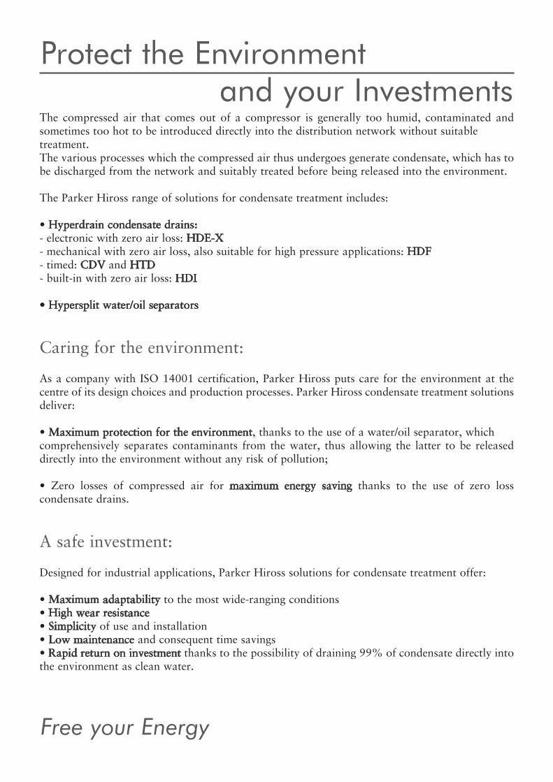
The compressed air that comes out of a compressor is generally too humid, contaminated andsometimes too hot to be introduced directly into the distribution network without suitabletreatment.The various processes which the compressed air thus undergoes generate condensate, which has tobe discharged from the network and suitably treated before being released into the environment.The Parker Hiross range of solutions for condensate treatment includes:• Hyperdrain condensate drains:- electronic with zero air loss: HDE-X- mechanical with zero air loss, also suitable for high pressure applications: HDF- timed: CDV and HTD- built-in with zero air loss: HDI• Hypersplit water/oil separators
Caring for the environment:As a company with ISO 14001 certification, Parker Hiross puts care for the environment at the centre of its design choices and production processes. Parker Hiross condensate treatment solutionsdeliver:• Maximum protection for the environment, thanks to the use of a water/oil separator, whichcomprehensively separates contaminants from the water, thus allowing the latter to be releaseddirectly into the environment without any risk of pollution;• Zero losses of compressed air for maximum energy saving thanks to the use of zero loss condensate drains.
A safe investment:Designed for industrial applications, Parker Hiross solutions for condensate treatment offer:• Maximum adaptability to the most wide-ranging conditions• High wear resistance• Simplicity of use and installation• Low maintenance and consequent time savings• Rapid return on investment thanks to the possibility of draining 99% of condensate directly intothe environment as clean water.

Sepa
rato
rsCo
nden
sate
dra
ins
with the Parker Hiross solutions
Hyperdrain HDE-Xzero loss electronic drains
Hyperdrain HDFzero loss mechanical drainseven for high pressures
Hyperdrain CDV and HTDtimed drains
Hypersplitoil/water separators
Hyperdrain HDI zero loss integrated drain
(1)
(2) (3)
(4)
Free your Energy
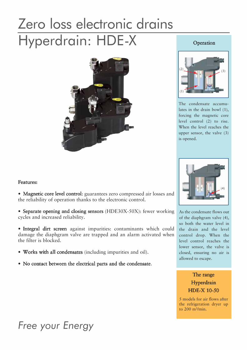
Zero loss electronic drainsHyperdrain: HDE-X Operation
The condensate accumu-lates in the drain bowl (1),forcing the magnetic corelevel control (2) to rise.When the level reaches theupper sensor, the valve (3)is opened.
As the condensate flows outof the diaphgram valve (4),so both the water level inthe drain and the level control drop. When thelevel control reaches thelower sensor, the valve isclosed, ensuring no air isallowed to escape.
Features:• Magnetic core level control: guarantees zero compressed air losses andthe reliability of operation thanks to the electronic control. • Separate opening and closing sensors (HDE30X-50X): fewer workingcycles and increased reliability. • Integral dirt screen against impurities: contaminants which coulddamage the diaphgram valve are trapped and an alarm activated whenthe filter is blocked. • Works with all condensates (including impurities and oil).• No contact between the electrical parts and the condensate.
The rangeHyperdrain
HDE-X 10-505 models for air flows afterthe refrigeration dryer upto 200 m3/min.

(1)(2)
(10)
(3)
(4) (5)
(6)
(7)
(8)(9)
All the benefits, in three steps:Installation• Condensate inlet (4) rotates for easy top or rear inlet connection (from HDE20X).• No programming or calibration required. • Balance line inlet (3, from HDE20X) for installation ease even in complex situations.Maintenance• Easy drain access and easily removable electrical connector (7) simplify maintenance.Use• Large cross section diaphgram valve (9) with pilot control improves reliability.• Alarm lamp (5) warns the user if the condensate cannot be discharged, protecting the systemfrom contamination. • Standard volt-free alarm contact (6, HDE30X-50X) allows remote monitoring.• Special outlet flow regulator (8) to throttle condensate flow, ensures no emulsion is created andsupports the oil/water separator installation.
1) Magnetic core level control2) Integral dirt screen3) Balance line inlet4) Condensate inlet5) Alarm lamp6) Volt free alarm contact7) Electrical connector8) Outlet flow regulator9) Diaphgram valve10) Bottom condensate inlet (from HDE30X)
Zero loss electronic drains
The Parker Hiross solutions

(1)
(2)
Free your Energy
Hyperdrain: HDF510
HDF is the result of a long and constanttechnological evolution, and combines theadvantages of zero loss operation withextreme ease of installation.
Features:• Hiroshield protection: even works with dirty, oily condensates. Highwearing, long operating life in even the most severe conditions. • Patented valve mechanism: finely calibrated design, long term reliability. All the benefits, in three steps:Installation• No need for electrical wiring, as power supply is not required. • No programming or calibration required, HDF is ready to use. • Also available with an internal vent line. Maintenance• Manual drain valve for system discharge and operational check fitted asstandard. Use• Large cross section outlet valve opening minimizes the chance of blockages for improved reliability. • Low velocity condensate outlet ensures that no emulsion is created andsupports installation of a static oil/water separator.
High pressure version featuring a robust housingcompletely coated with a choice of 3 materials foraggressive condensates: • carbon steel, • stainless steel & brass • stainless steel
3 HDF510 models forhigh pressures up to 51barg.
3 models for air flowsafter the refrigerationdryer up to 500 m3/min.
The rangeHyperdrain HDF
As the water exits the floatdrops. The valve re-closesbefore any air can escape.
Zero loss mechanical drainsHyperdrain: HDF Operation
With no water in the drainthe valve is closed - no airloss.
The rising water level forcesthe float (1) to rise andopen the valve (2). Thewater is allowed to exitwithout any air loss.
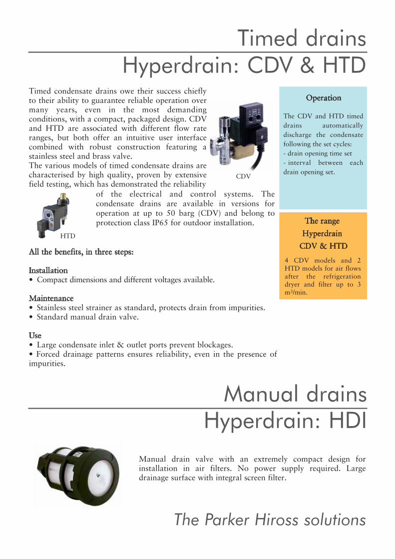
CDV
HTD
The Parker Hiross solutions
Manual drain valve with an extremely compact design for installation in air filters. No power supply required. Large drainage surface with integral screen filter.
Manual drainsHyperdrain: HDI
All the benefits, in three steps:Installation• Compact dimensions and different voltages available. Maintenance• Stainless steel strainer as standard, protects drain from impurities. • Standard manual drain valve. Use• Large condensate inlet & outlet ports prevent blockages. • Forced drainage patterns ensures reliability, even in the presence ofimpurities.
The rangeHyperdrainCDV & HTD
4 CDV models and 2HTD models for air flowsafter the refrigerationdryer and filter up to 3m3/min.
of the electrical and control systems. The condensate drains are available in versions for operation at up to 50 barg (CDV) and belong toprotection class IP65 for outdoor installation.
The CDV and HTD timeddrains automaticallydischarge the condensatefollowing the set cycles: - drain opening time set - interval between eachdrain opening set.
OperationTimed condensate drains owe their success chieflyto their ability to guarantee reliable operation overmany years, even in the most demandingconditions, with a compact, packaged design. CDVand HTD are associated with different flow rateranges, but both offer an intuitive user interfacecombined with robust construction featuring astainless steel and brass valve.The various models of timed condensate drains arecharacterised by high quality, proven by extensivefield testing, which has demonstrated the reliability
Timed drainsHyperdrain: CDV & HTD

Free your Energy
Oil/water separatorsHypersplit
Features:• Reliable, efficient and maintenance-friendly, Hypersplit guarantees rapid payback and up to99,9% of condensate safely discharged as clean water.• Twin tank models (OWS185; OWS485) feature patented parallel flow design, ensuring longeractive carbon life as well as significantly improved performance. • OWS125-485 with 4 inlet ports allow connection of up to 4 condensate lines onto oneHypersplit. • Single moulded construction for minimum weight and compact dimensions. Polyethylenethroughout construction prevents corrosion and leakages. • Inlet chamber, primary tank and main tank generously dimensioned, improving separation andreducing the risk of blockages. Accessories:
• Multibanking solution: for large installations, allowing up to 5 Hypersplit installations in parallel. • Additional oil containers: simplify maintenance.• Pre-filter: protects the carbon stage from bulk contamination, whilst the carbon stage itself hasbeen sized to ensure that the outlet water is free of any traces of oil.
(1)
(2)
(3)
(7)
(4)
(5)
(6)
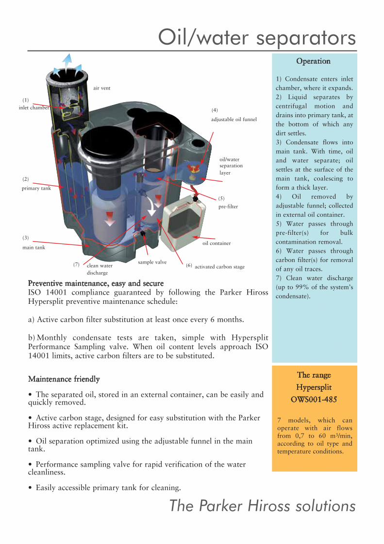
Oil/water separatorsOperation
1) Condensate enters inletchamber, where it expands.2) Liquid separates by centrifugal motion anddrains into primary tank, atthe bottom of which anydirt settles.3) Condensate flows intomain tank. With time, oiland water separate; oil settles at the surface of themain tank, coalescing toform a thick layer.4) Oil removed by adjustable funnel; collectedin external oil container.5) Water passes throughpre-filter(s) for bulk contamination removal.6) Water passes throughcarbon filter(s) for removalof any oil traces.7) Clean water discharge(up to 99% of the system’s condensate).
The rangeHypersplit
OWS001-485
7 models, which can operate with air flowsfrom 0,7 to 60 m3/min,according to oil type andtemperature conditions.
Preventive maintenance, easy and secureISO 14001 compliance guaranteed by following the Parker HirossHypersplit preventive maintenance schedule:a) Active carbon filter substitution at least once every 6 months. b)Monthly condensate tests are taken, simple with HypersplitPerformance Sampling valve. When oil content levels approach ISO14001 limits, active carbon filters are to be substituted.
Maintenance friendly• The separated oil, stored in an external container, can be easily andquickly removed. • Active carbon stage, designed for easy substitution with the ParkerHiross active replacement kit.• Oil separation optimized using the adjustable funnel in the maintank. • Performance sampling valve for rapid verification of the water cleanliness.• Easily accessible primary tank for cleaning.
The Parker Hiross solutions
inlet chamber
air vent
primary tank
main tank
clean waterdischarge
activated carbon stage
oil container
pre-filter
oil/water separationlayer
adjustable oil funnel
sample valve

m3/min m3/h m3/min m3/h m3/min m3/h IN OUT barg V/ph/Hz A B C kg
HDE10X - - - - 12 720 1xG1/2” G3/8” 16 115-230/1/50-60 67 110 146 0,5HDE20X 4 240 8 480 24 1440 1xG1/2” G3/8” 16 115-230/1/50-60 67 101 139 0,6HDE30X 7 420 14 840 42 2520 2xG1/2” G3/8” 16 115-230/1/50-60 67 122 164 1,0HDE40X 30 1800 60 3600 180 10800 2xG1/2” G3/8” 16 115-230/1/50-60 67 137 164 1,1HDE50X 100 6000 200 12000 600 36000 2xG1/2” G3/8” 16 115-230/1/50-60 67 197 164 1,5
HDF120 90 5400 180 10800 540 32400 1/2” 1/2” 16 - 156 111 108 0,9HDF180 100 6000 200 12000 600 36000 1” 1” 16 - 156 111 108 0,9HDF220 250 15000 500 30000 1500 90000 1” 1” 16 - 266 111 108 0,9
HDF510 100 6000 200 12000 600 36000 1” 1” 51 - 233 186 158 1,1HDF510S 100 6000 200 12000 600 36000 1” 1” 51 - 233 186 158 1,1HDF510C 100 6000 200 12000 600 36000 1” 1” 51 - 233 186 158 1,1
HDI - - - - 0,5-0,7 30-42 1/2” 1/2” 16 - 40 62 - 0,03
CDV/24 150 9000 300 18000 900 5400 1/2” 3/8” 16 24/1/50-60 90 110 90 0,7CDV/115 150 9000 300 18000 900 5400 1/2” 3/8” 16 115/1/50-60 90 110 90 0,7CDV/230 150 9000 300 18000 900 5400 1/2” 3/8” 16 230/1/50-60 90 110 90 0,7
CDV/50barg 150 9000 300 18000 900 5400 1/2” 3/8” 50 230/1/50-60 90 110 90 0,7HTD115 - - 6 360 - - 16 115/1/50 43 90 95 0,18HTD230 - - 6 360 - - 16 230/1/50 43 90 95 0,18
Free your Energy
A C
B
CA
B
A
B
C
B
AC
C
A
B
C
A
B
C
A
B
C
A
B
A C
B
A
B
HDF120-180 HDF220 HDF510 CDV
HDE10X HDE20X HDE30-40X HDE50X HTD115-230 HDI
Condensate drainsHyperdrain
Performances refer to 35°C compressed air temperature, 25°C ambient temperature, 65% R.H., 3°C pressure dew point (calculations with refrigeration dryer), 7 barg working pressure. Figures for refrigeration dryer and filter assume adequate condensate removal upstream. If installedafter the dryer, multiply the condensate drain air flow by 3; if installed after the filter, multiply the air flow by 6.
Modelfilterrefrigerant dryer
air flow
Zero loss electronic drains
Zero loss mechanical drains
Zero loss special mechanical drains
Zero loss internal drains
Timed drains
8mm hose8mm hose
connections maxpress.
power supply dimensions (mm) weight
m3/h m3/h m3/h m3/h m3/h m3/h
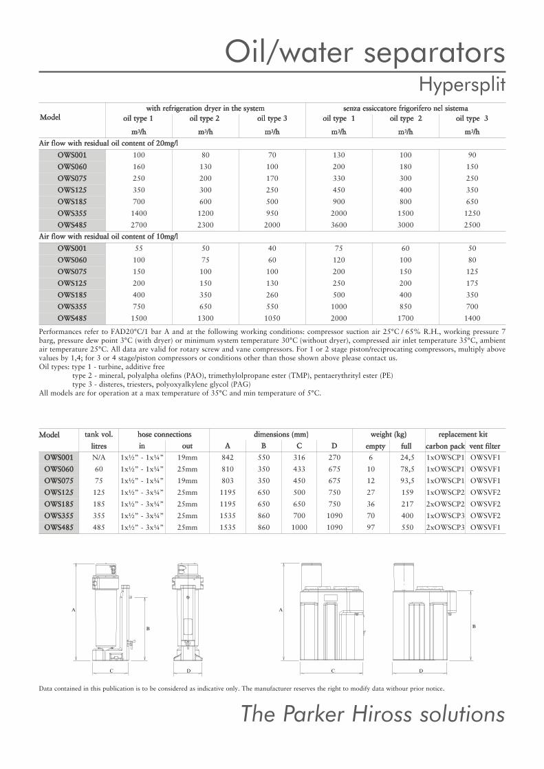
OWS001 100 80 70 130 100 90OWS060 160 130 100 200 180 150OWS075 250 200 170 330 300 250OWS125 350 300 250 450 400 350OWS185 700 600 500 900 800 650OWS355 1400 1200 950 2000 1500 1250OWS485 2700 2300 2000 3600 3000 2500
OWS001 55 50 40 75 60 50OWS060 100 75 60 120 100 80OWS075 150 100 100 200 150 125OWS125 200 150 130 250 200 175OWS185 400 350 260 500 400 350OWS355 750 650 550 1000 850 700OWS485 1500 1300 1050 2000 1700 1400
in out A B C DOWS001 N/A 1x½” - 1x¼” 19mm 842 550 316 270 6 24,5 1xOWSCP1 OWSVF1OWS060 60 1x½” - 1x¼” 25mm 810 350 433 675 10 78,5 1xOWSCP1 OWSVF1OWS075 75 1x½” - 1x¼” 19mm 803 350 450 675 12 93,5 1xOWSCP1 OWSVF1OWS125 125 1x½” - 3x¼” 25mm 1195 650 500 750 27 159 1xOWSCP2 OWSVF2OWS185 185 1x½” - 3x¼” 25mm 1195 650 650 750 36 217 2xOWSCP2 OWSVF2OWS355 355 1x½” - 3x¼” 25mm 1535 860 700 1090 70 400 1xOWSCP3 OWSVF2OWS485 485 1x½” - 3x¼” 25mm 1535 860 1000 1090 97 550 2xOWSCP3 OWSVF1
C
A
D
B
A
C
B
D
Data contained in this publication is to be considered as indicative only. The manufacturer reserves the right to modify data withour prior notice.
Model
Model tank vol.litres
hose connections dimensions (mm) weight (kg)empty full
replacement kitcarbon pack vent filter
with refrigeration dryer in the systemoil type 1 oil type 2 oil type 3 oil type 1 oil type 2 oil type 3
senza essiccatore frigorifero nel sistema
Air flow with residual oil content of 20mg/l
Air flow with residual oil content of 10mg/l
Oil/water separatorsHypersplit
Performances refer to FAD20°C/1 bar A and at the following working conditions: compressor suction air 25°C / 65% R.H., working pressure 7barg, pressure dew point 3°C (with dryer) or minimum system temperature 30°C (without dryer), compressed air inlet temperature 35°C, ambientair temperature 25°C. All data are valid for rotary screw and vane compressors. For 1 or 2 stage piston/reciprocating compressors, multiply abovevalues by 1,4; for 3 or 4 stage/piston compressors or conditions other than those shown above please contact us.Oil types: type 1 - turbine, additive free
type 2 - mineral, polyalpha olefins (PAO), trimethylolpropane ester (TMP), pentaerythrityl ester (PE)type 3 - disteres, triesters, polyoxyalkylene glycol (PAG)
All models are for operation at a max temperature of 35°C and min temperature of 5°C.
The Parker Hiross solutions

Copy
right
Parke
r Hiro
ss S.p
.A. 20
06
104
292 /
07-07
/ 1.00
0 / R
0
Free your EnergyRelease your Power
Save EnergyPurify your Air
Stop Wasting WaterRespect the Environment
Improve your Factory’s performancesFocus on your Core Business
Parker Hiross S.p.A.Strada Zona Industriale 4 - 35020 S. Angelo di Piove, PD - ITALY - tel.: +39 049 9712111 - fax: +39 049 9701911
[email protected] - www.dh-hiross.com