Embed Size (px)
Citation preview
CONCRETE WALLS AND GROUT CURTAINS IN THE TWENTY-FIRST CENTURY:
THE CONCEPT OF COMPOSITE CUT-OFFS FOR SEEPAGE CONTROL
Dr. Donald A. Bruce1 Trent L. Dreese2
Douglas M. Heenan3
ABSTRACT The state-of-practice in the design, construction and verification of concrete cut-offs, and grout curtains, as dam seepage remediations is reviewed. Recent experiences when attempting to build concrete cut-offs through hard and highly permeable rock masses have led the authors to develop the concept of “composite cut-offs“ for seepage control. A campaign of high quality drilling, permeability testing and grouting is first conducted to pretreat the very permeable and/or clay-filled zones, to seal the clean fissures, and to provide an extremely detailed geological basis upon which to design the location and extent of the subsequent concrete wall (if in fact needed). Bearing in mind that the average cost of a concrete wall is many times that of a grouted cut-off, and that there is currently a shortfall in industry capacity to construct the former, the concept of a “composite wall” is logical, timely and cost effective.
INTRODUCTION As documented by Weaver and Bruce (2007), grout curtains have been used in the U.S. to control seepage in rock masses under and around dams of all types since the 1890’s. For a variety of understandable, if not always laudable reasons, the long-term performance of many of these curtains has not been satisfactory, especially in lithologies containing soluble and/or erodible materials. Foundation remediation in such instances traditionally involved regrouting, often of course, using the same means, methods and materials whose defects were the underlying cause of the inadequacy in the first place. Disillusionment on the part of owners and engineers with the apparent inability of these traditional grouting practices to provide a product of acceptable efficiency and durability led to the chorus of “grouting doesn’t work” voices in the industry from the mid-1970’s onwards. The fact that effective and durable grout curtains were being installed successfully elsewhere in the world, using different perspectives on design, construction and contractor procurement processes, largely escaped the attention of the doubters who, for all their other and obvious qualities, exhibited technological xenophobia.
1 President, Geosystems, L.P., P.O. Box 237, Venetia, PA 15367, U.S.A.; Phone: (724) 942-0570; Fax:
(724) 942-1911; Email: [email protected]. 2 Vice President, Gannett Fleming Inc., 207 Senate Avenue, Camp Hill, PA 17011, U.S.A.; Phone: (717)
763-7211 x2686; Fax: (717) 303-0346; Email: [email protected]. 3 Vice President, Advanced Construction Techniques Ltd., 3935 Lloydtown Aurora Road, Kettleby, ON
L0G 1J0, Canada; Phone: (905) 939-7755; Fax: (905) 939-9305; Email: [email protected].
Partly as a result of the anti-grouting lobby, equally in response to indisputable geological realities and challenges, and building on technical advances in “slurry wall” techniques, the concept and reality of “positive cut-offs” became the mantra for major embankment dam foundation rehabilitation in North America from 1975 onwards. Such walls, built through and under existing dams by either the panel wall technique, or secant large diameter piles, comprise some type of concrete, ranging from high strength to plastic. In contrast to grout curtains, where well over 90% of the cut-off is, in fact, the virgin, in situ rock, these “positive” cut-offs were, in theory, built of 100% pre-engineered material of well-defined properties. The necessity for such “positive” cut-off walls remains today in certain geological conditions, and the list of successful projects is extremely impressive (Bruce et al., 2006; Bruce, 2007). From the mid-1980’s – albeit in Europe (Lombardi 2003) – a new wave of dam grouting concepts began to emerge. Given that most of the leading North American practitioners had close corporate and/or professional and personal links with this insurgency, it is not surprising that their heretofore moribund industry began to change. By the time of the seminal 2003 ASCE grouting conference in New Orleans, the revolution in North American practice for dam foundation grouting had been clearly demonstrated (Wilson and Dreese, 2003; Walz et al., 2003). The concept of a Qualitatively Engineered Grout Curtain was affirmed. Differences in opinion and philosophies with the great European practitioners such as Lombardi, the architect of the GIN Method, were not necessarily resolved: they were debated between equals and the respective opinions fairly acknowledged. It is therefore the case that, in North America, there is now expertise and experience of an unparalleled level in both grout curtains and concrete cut-off walls. This is particularly serendipitous given that the dollar requirement for the application of both technologies – in Federal dams alone in the next 5 years – is of an order equivalent to the aggregate of the preceding 40 years (Halpin, 2007). This paper presents a review of the current state-of-practice in each of these two technologies and, in the case of concrete cut-offs, provides a historical review of the 20 projects executed to date in North America. The paper further describes how these techniques can be combined in the concept of a “composite cut-off” which has potentially extraordinary benefits to owners in the financial sense, while still assuring the highest verifiable standards of performance and durability in the field.
CUT-OFF WALLS Historical Review of Projects The study by Bruce et al. (2006) identified thirty case histories of embankment dams remediated against seepage by some type of “positive” cut-off wall. That list included ten projects wherein Deep Mixing Methods, or a continuous cement-soil-bentonite wall, had been built. Omitting these examples, where the wall either comprises “soilcrete,” or where the cut-off practicability and/or depth is severely restricted, there remain a total of

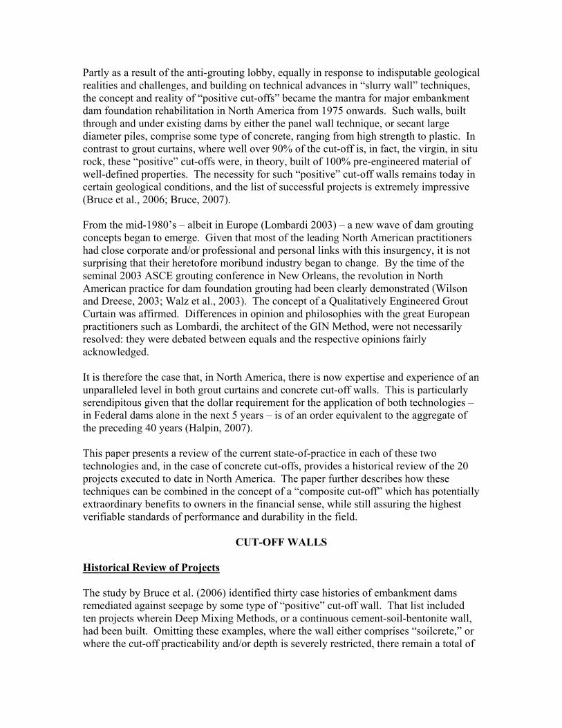
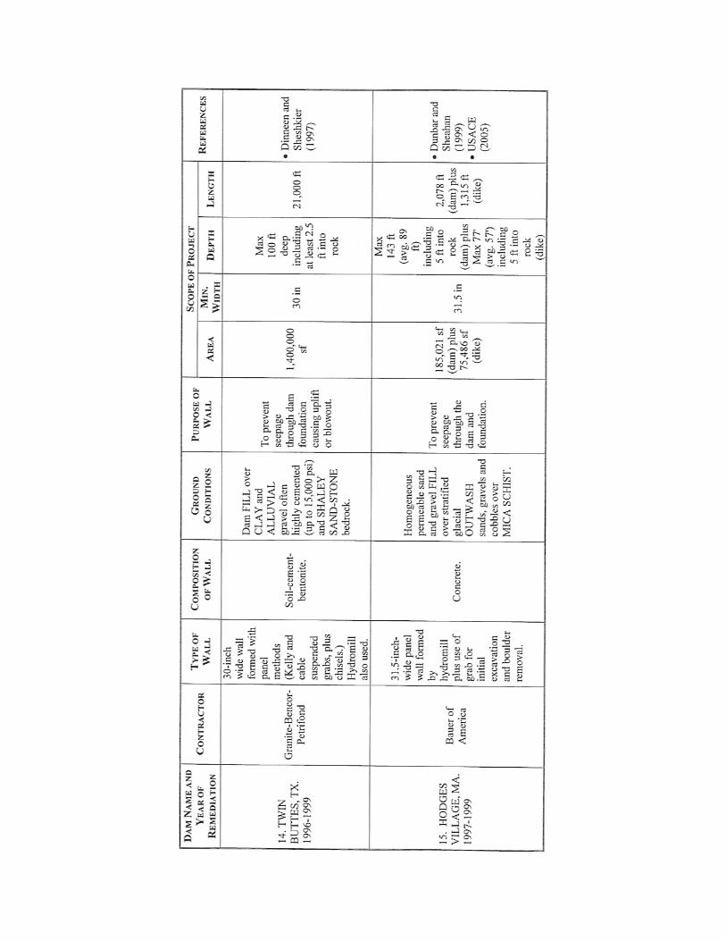
20 projects in North America where a deep, cut-off comprising completely engineered concrete backfill material has been constructed (Table 1, Figure 1). For information, Figure 2 illustrates panel wall construction
Tabl
e 1.
Det
ails
of r
emed
ial d
am c
ut-o
ff p
roje
cts u
sing
pan
el o
r sec
ant c
oncr
ete
cut-o
ffs.
* S
olet
anch
e ha
ve o
pera
ted
in th
e U
.S. u
nder
diff
eren
t bus
ines
s ide
ntiti
es o
ver t
he y
ears
. “S
olet
anch
e” is
use
d he
rein
as t
he g
ener
al te
rm.


Not
e: A
ll re
fere
nces
may
be
foun
d in
Bru
ce e
t al.
2006
.

Not
e: A
ll re
fere
nces
may
be
foun
d in
Bru
ce e
t al.
2006
.
Figu
re 1
. Pr
ojec
t lis
ting
show
ing
chro
nolo
gy, t
ype
of c
ut-o
ff a
nd sp
ecia
lty c
ontra
ctor
.

Figure 2. Diaphragm wall panel construction sequence. and Figure 3 illustrates the principle of secant wall construction. Table 2 summarizes the volume of work represented by these 20 projects. As illustrated in Figure 1, there is a small but very highly qualified group of specialty contractors with the requisite resources, experience and expertise to conduct this work.
Figure 3. Construction sequence for a secant cut-off wall (Bruce and Dugnani, 1995).

Table 2. Concrete Cut-Offs for Existing Embankment Dams.
SQUARE FTAGE TYPE OF CONSTRUCTION NUMBER OF PROJECTS SMALLEST LARGEST TOTAL
Mainly Clamshell 7 51,000 1,400,000 3,986,320
Mainly Hydromill 9 104,600 850,000 2,389,415
Mainly Secant Piles 4 12,000 531,000 1,050,700
Total 20 7,426,435
Lessons Learned Investigations, Design, Specifications and Contractor Procurement
• Intensive, focused site investigations are essential as the basis for cut-off design and
contractor bidding purposes. In particular, these investigations must not only identify rock mass lithology, structure and strength (“rippability”), but also the potential for loss of slurry during panel excavation. This has not always been done, and cost and schedule have suffered accordingly on certain major projects.
• Special considerations have had to be made when designing cut-offs which must contact existing concrete structures, or which must be installed in very deep-sided valley sections, or which must toe in to especially strong rock.
• “Test Sections” have proved to be extremely valuable, especially for the contractor to refine his means, methods and quality control systems. Such programs have also given the dam safety officials and owners the opportunity to gain confidence and understanding in the response of their dams to the invasive surgery that constitutes cut-off wall construction. Furthermore, such programs have occasionally shown that the foreseen construction method was practically impossible (e.g., a hydromill at Beaver Dam, AR) or that significant facilitation works (e.g., pregrouting of the wall alignment at Mississinewa Dam, IN) were required.
• Every project has involved a high degree of risk and complexity and has demanded superior levels of collaboration between designer and contractor. This situation has been best satisfied by procuring a contractor on the basis of “best value,” not “low bid.” This involves the use of RFP’s (Requests for Proposals) with a heavy emphasis on the technical submittal and, in particular, on corporate experience, expertise and resources, and the project-specific Method Statement. These projects are essentially based on Performance, as opposed to Prescriptive Specifications . Partnering arrangements (which are post-contract) have proved very useful to both parties when entered into with confidence, enthusiasm, and trust.

Construction and QA/QC • The specialty contractors have developed a wide and responsive variety of equipment
and techniques to assure penetration and wall continuity in a wide variety of ground conditions. More than one technique, e.g., clamshell followed by hydromill, has frequently been used on the same project and especially where bouldery conditions have been encountered.
• Cut-offs can be safely constructed with high lake levels, provided that the slurry level in the trench can be maintained a minimum of 3 feet higher. In extreme geological conditions, this may demand pretreatment of the embankment (e.g., Mud Mountain Dam, WA) or the rock mass (Mississinewa Dam, IN) to guard against massive, sudden slurry loss.
• For less severe geological conditions, contractors have developed a variety of defenses against slurry losses of smaller volume and rate by providing large slurry reserves, using flocculating agents, and fillers in the slurry, or by limiting the open-panel width.
• Very tight verticality tolerances are necessary to assure continuity especially in deeper cut-offs. Such tolerances have been not only difficult to satisfy, but also difficult to measure accurately (to ≤ 0.5% of wall depth) and verify.
• The deepest panel walls have been installed at Wells Dam, WA (223 feet, clamshell) and at Mud Mountain Dam, WA (402 feet, hydromill). The hydromill has proved to be the method of choice for large cut-offs in fill, alluvials and in rock masses of unconfined compressive strengths less than 10,000 psi (massive) to 20,000 psi (fissile, and so, rippable).
• Secant pile cut-offs are expensive and intricate to build. However, they are the only option in certain conditions (e.g., heavily karstified, but otherwise hard limestone rock masses) which would otherwise defeat the hydromill. The deepest such wall (albeit a composite pile/panel wall) was the first — at Wolf Creek, KY in 1975 — which reached a maximum of 280 feet.
• A wide range of backfill materials has been used, ranging from low strength plastic concrete, to conventional high strength concrete.
• The preparation and maintenance of a stable and durable working platform has proved always to be a beneficial investment, and its value should not be underestimated.
• The highest standards of real time QA/QC and verification are essential to specify and implement. This applies to every phase of the excavation process, and to each of the materials employed.
• Enhancements have progressively been made in cut-off excavation technology, especially to raise productivity (particularly in difficult conditions), to increase mechanical reliability, and to improve the practicality and accuracy of deviation control and measurement.
Potential Construction Issues with Cut-Offs Satisfactory construction of positive cutoff walls requires experience, skill, and dedication to quality in every aspect of the construction process including site preparation,

excavation, trench or hole cleaning, concrete mixing, and concrete backfilling. Providing a positive cutoff requires that the elements of the wall be continuous and interconnected. The following issues are possible concerns that must be taken into account in wall construction to prevent defects. • Element deviation – Misalignment of the equipment or inability to control the
excavation equipment can result in deviation of elements and result in a gap in the completed wall.
• Uncontrolled Slurry Loss – Cutoff walls through existing water retaining structures
are almost always built to address seepage issues. Although bentonite slurries are proven in creating a filter cake in soils, the ability of bentonite slurries to form a filter cake in rock fractures is limited. As a general rule of thumb, if water is lost during exploration, one should assume that slurry losses in rock will occur. If the rock is sufficiently pervious, uncontrollable complete slurry loss can occur. Slurry losses in embankments have also occurred on past projects due to hydrofracturing of weak zones.
• Trench Stability – The factor of safety of slurry supported excavations in soil are not
high. Movement of wedges into the trench or “squeeze in” of soft zones can occur. • Concrete Segregation – Mix design and construction practices during backfill are
critical to prevent segregation or honeycombing within the completed wall. • Soil or Slurry Inclusions – The occurrence of soil or slurry filled defects or inclusions
in completed walls are a known issue. If small or discontinuous, these defects are not critical, but they are very significant if they fully penetrate the width of the wall.
• Panel Joint Cleanliness – Imperfections or pervious zones along the joints between
elements is a recognized source of leakage through completed walls. Cleaning of adjacent completed elements by circulating fresh slurry is necessary to minimize the contamination of joints.
Performance of Cut-Offs Surprisingly little has in fact been published to date describing the actual efficiency of cut-off walls after their installation: most of the publications describe design and construction and have usually been written soon after construction by the contractors themselves. Although there is some evidence (e.g., Davidson, 1990) that the walls have not always functioned as well as anticipated, it can be reasonably assumed that the majority of the remediations have been successful, provided a) the wall has been extended laterally and vertically into competent, impermeable and non-erodible bedrock; b) that there is full lateral continuity between panels with no clay contamination; and c) that the panels themselves contain no concrete segrations or slurry/soil inclusions. It may also be stated that the capabilities of the technology of the day have not always been able to satisfy the depth criterion. EM 1110-2-1901 published in 1986 by the USACE states

that the experienced efficiency of cutoff walls calculated based on head reduction across the wall was 90% or better for properly constructed walls. The term “properly” is not defined and no update to this information has been published by the Government.
GROUT CURTAINS General Statement Construction of grout curtains to mitigate seepage below proposed or existing hydraulic structures is a unique type of construction. This type of grouting involves managing and performing dozens of simultaneous operations, each of which requires an extraordinary degree of care and any of which, if not performed properly, will result in ineffective grouting and loss of value in the project. There is probably no other construction activity where quality and economy are more dependent on skill, and the depth of both theoretical and practical knowledge. It is also the nature of grouting that performing as much as 95% of the work properly can result in almost a total grouting program failure and almost total loss in program value. Studies of imperfect seepage barriers show that if only 5% of an otherwise impervious barrier is defective, the barrier efficiency in terms of seepage reduction can be as low as 20%. This is one of the major reasons why many grouting programs have later been found to perform so poorly. Grout curtains must therefore be executed with nearly 100% effectiveness using the technology that is now available. Grouting equipment, methods and contracting procedures have evolved dramatically over the last decade and the industry can now design, build and verify the performance of permanent grouted seepage barriers for dam structures. In the Twenty First Century, technology, tools, and procedures are available that permit design and construction of grout curtains as engineered elements of a water retaining structure. Prior to the 1980’s, very little in the way of design was performed for foundation cutoffs. Grout curtain configuration and depths were selected based on rules of thumb often ignoring the site specific geologic conditions (Wilson and Dreese, 1998). The grout mixes used in North America prior to the 1990’s were commonly neat cement grouts with an unstable rheology during injection, significant bleed potential and poor durability. The current state of the practice in North America is to design the grout curtain as an engineered element, utilize additives and admixtures to create balanced stable grouts, use measurement while drilling and borehole imaging equipment to “see” underground, and use computer assisted monitoring to manage the grouting activities and to evaluate the achieved results to confirm that the design requirements have been achieved. Quantitatively Engineered Grout Curtains Designing grout curtains based on rules of thumb without consideration of the site geology is no longer and acceptable practice. Specific project design establishing the required performance of the completed curtain is now commonly performed (Figure 4). Grouting designs must be site specific to address the specific project goals (Wilson and Dreese, 1997). The performance criterion from the quantitative design identifies the

maximum permissible residual permeability and minimum width of the grouted zone. Prerequisite information required to perform quantitative design of a grout curtain include (Wilson and Dreese, 1998, 2003): • Thorough geologic investigations identifying structure, stratigraphy, weathering, and
hydraulic conductivity of the foundation rock.
Figure 4: Analysis of Data from Recent Projects Using State of Practice Methods. • Establishment of project performance requirements in terms of seepage quantities and
seepage pressures. Design requirements should consider dam safety, cost, and political acceptability or public perception as they relate to residual seepage.
• Seepage analyses to determine the need for grouting, the horizontal and vertical limits of the cutoff, the width of the curtain, and the location of the curtain.
• Where relevant, the value of the lost water should be compared to the cost of more intensive grouting in a cost benefit analysis.

• Specifications written to require best practice for field execution of every element of the work.
Quantitative design of grouting requires that the curtain be treated in seepage analyses as an engineered element. The specific geometry of the curtain in terms of depth and width must be included in the model and the achievable hydraulic conductivity of the curtain must also be assumed. Guidance on assigning grout curtain design parameters and performing seepage analyses for grout curtains is covered in detail by Wilson and Dreese (2003). More substantial and complete guidance on flow modeling of grouted cutoffs will be included in the update to USACE EM 1110-2-3506 to be issued in 2008. Grout Mix Design General Considerations The vast majority of grout curtains in North America constructed prior to 1990 utilized neat cement grouts with little consideration of the grout properties other than the water cement ratio. Today, grout mix designs are tailored to the application and desired results. Most rock grouting is performed with high mobility grouts (HMG). Fundamental properties of HMG to be considered when developing a mix design include the grain size of the particulate constituents, viscosity, cohesion, sedimentation or bleed potential, segregation, resistance to pressure filtration, particle agglomeration minimization during injection, resistance to washout, matrix porosity, and durability (Chuaqui and Bruce, 2003). The desired grout is one that will penetrate the fractures a sufficient distance to provide overlap of grouted zones, but will have sufficient cohesion to not travel too far while having a viscosity that permits the grout to be injected in a reasonable amount of time. During injection the grout will have a constant or nearly constant rheology and once in place the grout will not bleed or washout prior to hardening. Once hardened, the grout will be resistant to leaching and provide permanent seepage control. Balanced Stable Grouts The term stable is defined as a grout mixture that exhibits less than 5% bleed. With the available technology in mix designs today, zero bleed grouts can be formulated for most applications. The term balanced refers to a grout mixture that is formulated to provide the desired rheological properties that should remain constant during the injection process. The use of additives in cement-based grouts allows one to achieve improved rheological properties. Each additive is used to effect a positive change in one or more properties of the grout. Unfortunately, the additive may improve one property while adversely affecting other properties. This negative impact can often be offset with additional additives. Table 3 provides a list of common additives and admixtures, lists the typical concentration used, identifies their beneficial and adverse effects, and provides other comments pertinent to their use. Additional information on additives and admixtures for HMGs, mix designs, and testing can be found in Chuaqui and Bruce (2003), Weaver and Bruce (2007) and the forthcoming update to the USACE Grouting Technology Manual.

Grout components including cement, flyash, bentonite and silica fume often vary chemically from one source to another. The only components likely to be constant are the welan gum and the superplasticizer. Due to the variability of the components from source to source, it is essential that a full-scale mix design program be carried out prior to production grouting. This mix testing should be performed using all the actual components and actual mixing and proportioning equipment intended for use in the production program including the mix water. The fluid properties of balanced stable grouts can be varied widely depending on the application. For a typical grout curtain in fractured rock, a low cohesion is desirable and a range of apparent viscosities ranging from a low of 35 to 40 seconds to a maximum value of 60 to 70 seconds would be common. A minimum 5 second change in Marsh funnel flow time should be provided and a 10 second change between mixes is common for the thinner mixes. With balanced stable grouts, the various mixes are designed to achieve the desired viscosity and cohesion. Thin mixes have low viscosity and low cohesion (higher mobility), while thick mixes have higher viscosity and higher cohesion. The injected mix is progressively thickened in response to conditions observed in the stage. In karst applications, the range of apparent viscosities is often larger and often includes mixes with an infinite Marsh funnel flow time that require testing with a flow cone. In addition to the HMG mixes, sanded grouts and Low Mobility Grouts (LMG) are also commonly applied to treat larger karst features.
Table 3. Common Grout Additives (Adapted from Wilson and Dreese, 1998).
Additive Beneficial Effects Adverse Effects Other Comments
Flyash Type C or Type F Typical Concentration is 10 to 30% by weight of cement.
Improves grain size distribution of cured grout, Cheap filler with pozzolanic properties. Can be used as a replacement for some of the cement and reacts with the free lime resulting from the cement hydration process. Increases durability and resistance to pressure filtration.
Increases viscosity and cohesion.
Concentrations of Type C flyash in excess of 20% by weight of cement should be avoided.
Bentonite Typical Concentration is 2 to 4% by weight of cement.
Reduces bleed and increases resistance to pressure filtration. Slight lubrication and penetrability benefits.
Increases viscosity and cohesion. Weakens grout.
Should be added as pre-hydrated suspension. Concentrations in excess of 5% should be avoided.
(continues)

Additive Beneficial Effects Adverse Effects Other Comments
Silica Fume Typical concentration is 8% by weight of cement as this is the commonly available preblended concentration.
Fine grained powder which improves pressure filtration resistance and reduces bleed. Improves water repellency and enhances penetrability. Improves grain size distribution of cured grout.
Increases viscosity and cohesion.
Difficult to handle due to fineness.
Viscosity Modifiers (Welan Gum) Typical Concentration is 0.1% by weight of cement.
Makes the grout suspension more water repellant, provides resistance to pressure filtration, and reduces bleed.
Increases viscosity and cohesion.
At higher doses, provides some thixotropy to the grout which is helpful for artesian conditions.
Dispersants or Water Reducers (Superplasticizer, fluidifier) Typical Concentration is 1 to 3% by weight of cement.
Overprints solid particles with a negative charge causing them to repel one another. Reduces agglomeration of particles thereby reducing grain size by inhibiting the development of macro-flocs. Also reduces viscosity and cohesion.
Depending on chemistry chosen, may accelerate or retard hydration process. This is not necessarily negative.
Dispersants have a distinct life span. Working life depends on dispersant chemistry chosen.
Computer Monitoring and Analysis General Statement The current state of the art in grouting monitoring and evaluation is a fully integrated system where all field instruments are monitored in real time through a computer interface, all necessary calculations are performed automatically, grouting quantity information is tabulated and summarized electronically, program analyses are conducted automatically by the system using numerous variables, and multiple, custom as-built grouting profiles are automatically generated and maintained real-time. This level of technology provides the most reliable and high quality project records with minimal operator effort. Since all data are in electronic format, these systems lend themselves to customization of project records for specific project needs and sharing of project data. Features that may be included in fully integrated systems include: automatic tagging of data with geologic units; graphical stage records showing mix changes; 3-D representations of data; CADD fully integrated with the data collection and database systems; easily customizable displays to provide the most effective graphical representation of data and results; creation of project specific, custom drawing sets

illustrating the relationships between one or multiple variables; a broad range of database query functions for both analysis of results and work planning; automatically generated closure plots with user defined limits based on geologic units or based on specified horizontal and vertical limits; electronic links to project data including boring logs, drawings, photos, etc; and full onsite capability to produce any desired output product rapidly. Figure 5 shows the interior of an “Intelligrout” control unit in the field. Advantages of Computer Monitoring
The application of computer monitoring technology has been found to substantially decrease grouting program costs and provide unprecedented levels of assurance that the desired results are being achieved (Dreese et al., 2003). There are marked cost savings due to a reduction in the number of personnel required onsite, the time required to execute field operations such as pressure testing and grouting, and the time to compile and maintain project records. Additionally, application of technology helps ensure that the grouting program is effective, in that effort is expended where it is required and reduced where it is not required. Time and money are spent treating the bad areas and limited in verifying results in good areas. The specific quality, cost, and time benefits that can be attributed to computer monitoring and analysis technology can be summarized as follows: • Real time data are obtained at much smaller time intervals (2-10 sec. frequency vs. 5-
15 min. frequency).
Figure 5: “IntelliGrout” Computer Monitoring System.
• Eliminates missing critical events such as pressure spikes. • Data obtained are more accurate than data from “conventional” methods. • Higher grouting pressures can be used with confidence. • Formation responses to procedure changes (mix or pressure) are known quickly. • Damage or no damage to a formation due to over-pressuring can be easily detected or
determined. • Significant acceleration of pressure testing and grouting operations. • More consistent grouting procedures due to central control location. • Reduction in inspection manpower requirements. • Provides detailed, permanent graphic records showing the entire time history for each
operation on each stage. • Profiles indicating grouting results are displayed such that the magnitude of the water
tesing and grout takes are color coded and scaled based on magnitude permitting rapid identification of areas requiring additional work and areas where project performance goals have been satisfied.
• Custom grouting specific queries permit access to any relevant data stored in the database
• Permits reallocation of resources to analysis of program results rather than on process management and data collection.
Measurement While Drilling and Borehole Imaging
Modern drilling recording instruments and borehole imaging technology allow for better understanding of subsurface conditions than was previously possible. Measurement While Drilling (“MWD”) instrumentation provides additional information during the drilling of every hole on a grouting project (Bruce and Davis, 2005). Specific energy and other recorded data can be evaluated and compared to the grouting data to procure as much information as possible from every hole drilled. Each hole on a grouting project is thereby treated as an exploration hole and the data gathered are utilized to increase the understanding of subsurface conditions. After a hole has been drilled, borehole imaging can be performed to obtain a “virtual core.” This equipment is especially useful on destructively drilled production holes where recovered core is not available for viewing and logging. These devices essentially permit the grouting professional to see underground. Borehole imaging units are capable of collecting images of the borehole sidewall and discontinuity data in a single pass (Figure 6). The data are then processed using the accompanying software. Data processing will include generation of borehole deviation charts showing the actual hole location in plan, section and profile; production of color borehole sidewall images; and mapping of visible discontinuities on the sidewall images including corrections for borehole deviation. This equipment provides invaluable data such as measurements of fracture apertures and bedrock discontinuity geometry. These are then utilized in designing or modifying the grout methods and materials. Borehole images are mapped by qualified personnel and the data may be further analyzed using stereonets analyses.
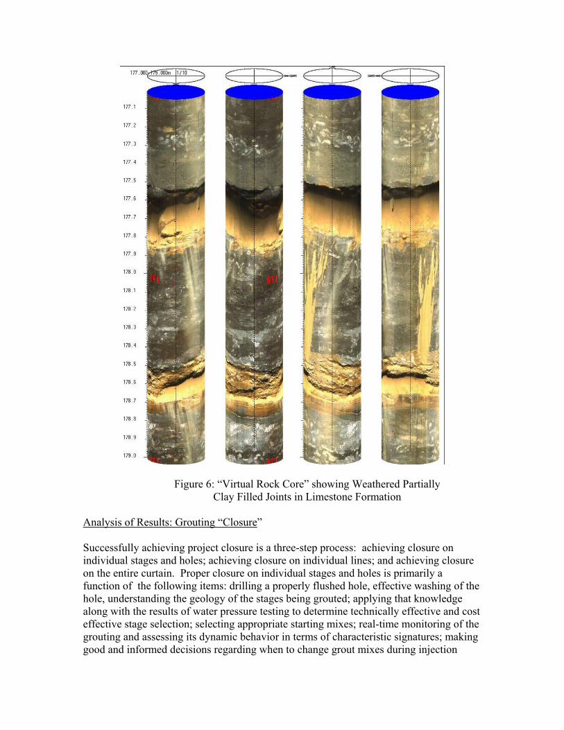
Figure 6: “Virtual Rock Core” showing Weathered Partially Clay Filled Joints in Limestone Formation
Analysis of Results: Grouting “Closure”
Successfully achieving project closure is a three-step process: achieving closure on individual stages and holes; achieving closure on individual lines; and achieving closure on the entire curtain. Proper closure on individual stages and holes is primarily a function of the following items: drilling a properly flushed hole, effective washing of the hole, understanding the geology of the stages being grouted; applying that knowledge along with the results of water pressure testing to determine technically effective and cost effective stage selection; selecting appropriate starting mixes; real-time monitoring of the grouting and assessing its dynamic behavior in terms of characteristic signatures; making good and informed decisions regarding when to change grout mixes during injection

within a stage; and managing the hole to completion (i.e., refusal to further grout injection) within a reasonable amount of time (Figure 7). The key is to gradually reduce the Apparent Lugeon Value of the stage (i.e., its Lugeon value calculated using grout as the test fluid, and taking into account the apparent viscosity of the grout relative to water) to zero. Pumping large quantities of grout for an extended period of time without any indication of achieving refusal is generally a waste of time and grout. Unless a large cavity has been encountered, the grout being used in this case has a cohesion that is too low and is simply traveling a great distance through a single fracture. Mix changes need to be managed properly for economy and value.
Figure 7: Time History Plot of Grouting Stage Demonstrating Closure,
i.e., reduction in “Apparent Lugeon Value” to zero. Each line of a grout curtain and the completed curtain where multiple lines are installed should be analyzed in detail. Each section of the grout curtain should be evaluated and closure plots of pre-grouting permeability for each series in the section plotted. As grouting progresses, the plots should show a continual decrease in pre-grouting permeability for each successive series of holes. For example, the results for the exploration holes and primary holes from the first line within a section represent the

“natural permeability” of the formation. Secondary holes on each line should show a progressively reduced permeability compared to the primary holes due to the permeability reduction associated with grouting of the Primaries. Similarly, the pre-grouting permeability of tertiary holes should show a marked decline relative to the secondary holes. For multiple line curtains, these plots are developed based on the sequence of grouting by holes series on each line (Figure 8). Evaluations can be performed by both elevation and by geologic strata. Analysis of these plots allows for extrapolation of the permeability after grouting the last series of holes. Verification holes can be used to confirm the validity of the extrapolations.
A-LINEC-LINE
B-LINE
PRIMARY
SECONDARY
TERTIARY
QUATERNARY
12
1
6
22
1
19
36
1
15
41
5
11
0
5
10
15
20
25
30
35
40
45
LUG
EON
V
ALU
E
Figure 8: Closure Evaluation for a Multiple Line Grout Curtain.
Closure diagrams are an extremely powerful tool, but only if they are applied correctly: a closure diagram that includes both “apples” and “oranges” is not only relatively meaningless, it may lead to erroneous conclusions that can be either too conservative or too liberal in terms of evaluating grouting effectiveness. In order to be valid, closure diagrams must be built up on a series of levels, each of which is based on similar conditions. The technical personnel must have particular experience in selecting appropriate data sets for closure analyses. Prior to the implementation of computer monitoring, the number of closure diagrams that could be prepared and used for assessment was limited by the onsite resources available to perform that effort. Many projects were performed without using any closure diagrams at all, often with the result that the performance was unsatisfactory. It required extensive hours of data entry, and the number of trial “groupings” was limited by the effort required to extract and compare multiple diagrams. On a typical large project that was being executed with a high level of diligence, an effort of more than a thousand man-hours might have been devoted to this activity and, even with that effort, not all of the permutations that might have been of value were generated. The capabilities of computer monitoring make this task very easy. All of the data required to construct the diagrams

can be automatically recorded in a database, and custom programmed query functions can be written to easily extract, analyze, and plot the data for evaluation. For example, closure diagrams can be generated automatically between variable station lengths, elevation, stage, or geologic unit. The results are applied in making well-founded decisions about the effectiveness of closure and the need for additional or reduced treatment in localized areas. It provides a level of confidence in grouting that was previously unable to be realized. In addition to performing the analyses described above, it is also necessary to review profiles indicating the geology, water testing, and grouting results. Review of the profiles with the water Lugeon values displayed on each zone or stage allows for confirmation that the formation behavior is consistent with the grouting, and permits rapid evaluation of any trends or problem areas requiring additional attention. In addition, this review permits identification of specific holes or zones within a hole that behaved abnormally and which are adversely skewing the results of the closure analysis. For example, the average pre-grouting permeability of tertiary holes that appears on a closure analysis plot may be 10 Lugeons, but that average may be caused by one tertiary hole that had an extraordinarily high value. That information will be available by analysis of the profiles and can be confirmed with the data set returned by the query that generates the closure plot. Review of the grout line profiles with the grout takes displayed is also necessary along with comparison of the average grout takes compared to the average Lugeon values reported by the closure analysis. Areas of abnormally high or low grout takes in comparison to the Lugeon values should be identified for further analysis. The grouting records for these abnormal zones should be reviewed carefully along with the pressure testing and grouting records from adjacent holes. Other relevant displays of the grouting data include permeability or grout take histograms by hole series, average grouting time per hole series, queries of the final hole series listing stages with a permeability greater than the performance goals, number of water losses or connections by hole series, piezometric levels versus time and hole series completion, and any other plots that make sense for the project being completed.
“COMPOSITE” CUT-OFFS Basic Premise In recent years, there has been a number of projects, both completed and in planning, which have featured the construction of a concrete cut-off wall installed through the dam and into karstified limestone bedrock. The basic premise of such a “positive” cut-off is clear and logical: the presence of large clay-filled solution features in the bedrock will defeat the ability of a grout curtain – even when designed and built using best contemporary practices – to provide a cut-off of acceptable efficiency and durability. This is particularly important when permanent “walk-away” solutions are required which must be robust, reliable and durable. There is no question that rock fissure grouting
techniques are incompatible with satisfying that goal in the presence of substantial clayey infill materials. However, the benefits of a concrete cut-off come at a substantial premium over those provided by a grout curtain. A typical industry average cost for a grouted cut-off is of the order of $25-$40 per square foot. The cost of a concrete cut-off is anywhere from 3 to 10 times this figure, depending on the technique (i.e., panel or secant), the ground conditions, the depth of the cut-off, and the nature of the site logistics. Furthermore, the construction of a concrete cut-off wall through the typical karstified limestone or dolomite rock mass will involve the excavation of the rock (which in the main part will be in fact very hard, impermeable, and competent with UCS values in excess of 20,000 psi) and backfilling that thin excavation with a material of strength 4,000 psi or less. In effect, great effort and expense is expended to provide a membrane (through the greater part of the project) which is of lower strength than the rock mass excavated to construct it. Another practical factor that has often been overlooked historically is that construction of a concrete wall may simply not be feasible in ground conditions which permit the panel trench stabilizing medium (i.e., bentonite slurry) or the drill flush (air or water) to be lost into the formation: in extremis either of these phenomena could create a dam safety threat, let alone the loss of very expensive excavation or drilling equipment at depth. The solution, not surprisingly, in such situations has been to suspend the wall construction and to systematically and intensively pretreat the formation by grouting. In doing so, however, it has not been always the case that the designer of the wall has appreciated that, in addition to this campaign of drilling, water pressure testing and grouting constituting a facilitating improvement to the rock mass, such work also generates a most detailed site investigation – at very close centers – of the whole extent of the originally foreseen concrete cut-off area. It would be reasonable, therefore, to propose that the data from these pretreatment programs could be used to review the true required extent of the subsequent concrete wall, and thereby reduce overall project costs with sound engineering justification. The concept may then be taken a stage further. Instead of drilling and grouting being conducted only as a remedial/facilitating operation under emergency conditions, specify it, as an originally foreseen designed concept to: • allow the location and extent of the major karstic features, which actually require
cutting off with a concrete wall, to be precisely identified; • pretreat the ground, and especially the epikarst, to an intensity that bentonite slurry or
drill flush will not be lost during the concrete wall construction. A typical criterion is 10 Lugeons;
• grout, to a verified engineered standard, the rock mass around and under the karstic features and which does not contain erodible material in its fissures. A typical criterion is in the range 1-3 Lugeons.
By embracing these precepts, it is therefore logical to propose the concept of a “composite cut-off”: an expensive concrete wall where actually required for long-term performance certitude, plus a contiguous and enveloping grout curtain to provide

acceptable levels of impermeability and durability in those portions of the rock mass with minimal erodible fissure infill material. Illustrative Examples With one eye on the immediate future requirements of seepage remediation involving cut-offs under dams, it may be stated that karst is either stratigraphically driven, or structurally related. Figure 9 a) shows a case where the major horizon of long-term seepage and erosion concern is limited to the 30 feet or so of epikarst; Figure 9 b) is the case where the seepage and erosion concern is in a particular deep stratigraphic member; and Figure 9 c) shows the condition where the karstification has developed along discrete structural discontinuities. For the sake of argument, assume that the cut-off has to be 1,000 feet long, the cost of drilling and grouting is $30 per square foot, that of the concrete wall costs $120 per square foot and that the maximum vertical extent of the cut-off is 110 feet (a massive shale aquiclude exists at 100 feet). The dam itself is “invisible” in this exercise. For the configuration of Figure 9 a), the original design features a concrete cut-off wall extending 10 feet into the aquiclude. The cost would therefore be 1,000 feet x 110 feet x $120 = $13.2 million. (This would, however, assume that construction of the wall through the epikarst would be feasible without pretreatment.) Alternatively, if the entire alignment were to be pregrouted, it would be revealed that there was no need to construct the wall deeper than, say 35 feet. The total cost of this composite wall would therefore be: Drill and Grout: 1,000 feet x 110 feet x $30/sft. = $3.3 million Plus Wall: 1,000 feet x 35 feet X $120/sft. = $4.2 million $7.5 million
Figure 9 a). Epikarst is found during pregrouting to an average of 30 feet b.g.s.
The concrete cut-off needs only to be installed to 35 feet b.g.s.

Figure 9 b). Heavily karstified horizons are found at depth. Therefore the concrete cut-
off is required for the full extent. The grouting has pretreated the karstic horizons to permit safe concrete cut-off construction.
Figure 9 c). Discrete karstic features have been found, structurally driven.
Thus, individual concrete cut-offs can be installed, after drilling and grouting has confirmed the extent of these features and has pretreated them to permit
safe concrete cut-off construction.

• For configuration 9 b), the cost of the predrilling and grouting would be the same, i.e., $3.3 million. However, in this case, the concrete wall would have to be $13.2 million. The overall cost of the cut-off would therefore be $16.5 million. However, the pretreatment in advance of the concrete wall would assure that the wall could in fact be built in a cost-effective and timely fashion, i.e., without interruptions caused by massive slurry loss. The overall (high) project cost would simply be a reflection of a uniquely challenging geological situation, i.e., a continuous bed of erodible material at depth.
• For configuration 9 c), the pretreatment would again cost $3.3 million. It would result in the identification of three discrete zones of structurally defined karst of combined area 3 x 80 feet x 40 feet = 9,600 sft. Therefore, the cost of the concrete wall actually needed to cut these features off would be 9,600 sft. x $120/sft. = $1,152,000. Thus, the total cost of the composite wall is $3,300,000 + $1,152,000 = $4.5 million.
Thus, the investment in the predrilling and grouting program generates very large savings in cases a) and c), whereas for case b) it assures that the wall which must be built, can be built without massive delays, difficulties, or – at worst – creating dam safety issues. Recommendations for Grouting for a “Composite Wall” Site Investigation and Assessment and Design • Research and utilize all the historical data (including original construction
photographs) which may have bearing on the development of a tentative geostructural model. An excellent example is provided by Spencer (2006).
• Conduct a new, thoughtful and focused site investigation to test the tentative geostructural model and provide prospective bidders with the kinds of information they truly need to estimate productivity and to quantify other construction risks.
• Develop an initial estimate of the extent of the composite cut-off and its respective components, i.e., concrete wall and grout curtain.
• Assess the adequacy of the existing dam and foundation instrumentation, and design and install additional monitoring arrays as appropriate. Revise the reading frequency protocols.
Preparation of Contract Documents and Contractor Procurement Methods • Create a Performance (as opposed to Prescriptive) Specification, while at the same
time clearly define what methods and techniques are not acceptable. Performance goals must be explicitly defined, together with their means of verification.
• Procure the specialty contractor on the “Best Value” basis, not “Low Bid”. • Mandate “Partnering” as a minimum: favor “Alliancing” as the goal (Carter and
Bruce, 2005). • Separate general construction activities (e.g., office modifications, service relocation)
into a different contract, but leave the design and construction of the working platform to the specialist contractor.
Technical Aspects • If flush water has been lost during investigatory drilling, slurry will certainly be lost
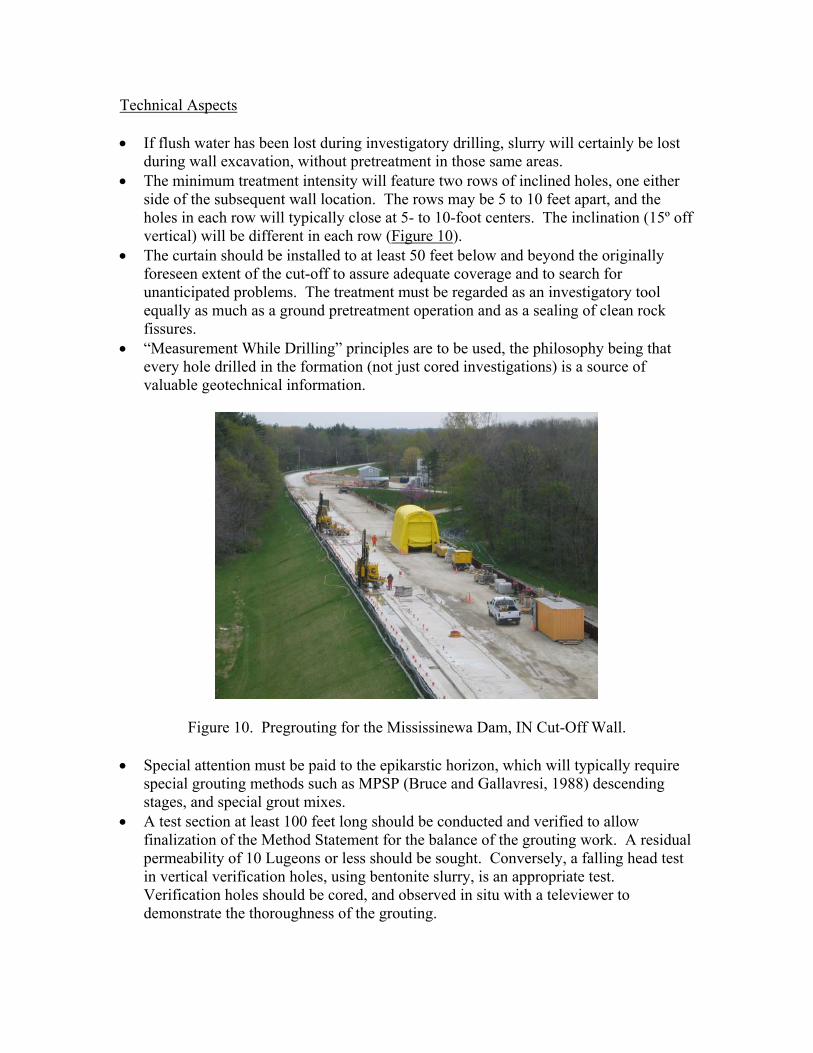
during wall excavation, without pretreatment in those same areas. • The minimum treatment intensity will feature two rows of inclined holes, one either
side of the subsequent wall location. The rows may be 5 to 10 feet apart, and the holes in each row will typically close at 5- to 10-foot centers. The inclination (15º off vertical) will be different in each row (Figure 10).
• The curtain should be installed to at least 50 feet below and beyond the originally foreseen extent of the cut-off to assure adequate coverage and to search for unanticipated problems. The treatment must be regarded as an investigatory tool equally as much as a ground pretreatment operation and as a sealing of clean rock fissures.
• “Measurement While Drilling” principles are to be used, the philosophy being that every hole drilled in the formation (not just cored investigations) is a source of valuable geotechnical information.
Figure 10. Pregrouting for the Mississinewa Dam, IN Cut-Off Wall. • Special attention must be paid to the epikarstic horizon, which will typically require
special grouting methods such as MPSP (Bruce and Gallavresi, 1988) descending stages, and special grout mixes.
• A test section at least 100 feet long should be conducted and verified to allow finalization of the Method Statement for the balance of the grouting work. A residual permeability of 10 Lugeons or less should be sought. Conversely, a falling head test in vertical verification holes, using bentonite slurry, is an appropriate test. Verification holes should be cored, and observed in situ with a televiewer to demonstrate the thoroughness of the grouting.

• In terms of the details of execution, the principles previously detailed to create Quantitatively Engineered Grout Curtains should be adopted. Thus, one can anticipate stage water tests, balanced, modified, stable grouts, and computer collection, analysis and display of injection data. When drilling the verification holes (at 25- to 100-foot centers between the two grout rows), particular care must be taken to assure that no drill rods are abandoned within the alignment of the wall since this steel will adversely impact subsequent wall excavation techniques.
• Grouting pressures at refusal should be at least twice the foreseen maximum slurry pressure exerted during panel construction.
Construction • The work must be conducted in accordance with the Contractor’s detailed Method
Statement which, in turn, must be in compliance with the minimum requirements of the Specification unless otherwise modified during the bidding and negotiation process. At the same time, modifications to the foreseen means and methods can be anticipated on every project, in response to unanticipated phenomena. Prompt attention to, and resolution of, these challenges are essential.
• As noted above, special attention is merited to the details of the design and construction of the working platform. The Contractor’s site support facilities (e.g., workshop, slurry storage and cleaning, concrete operations) can be completed and the utilities extended along the alignment (water, air, light, slurry) during the building of the work platform.
• The Test Section should be established in a structurally non-critical area, which does not contain the deepest extent of the foreseen concrete wall. The Test Section can, however, be integrated into the final works if it is proved to have acceptable quality.
• The concrete wall excavation equipment must have adequate redundancy, and must be supported by appropriate repair/maintenance facilities. A variety of equipment is usually necessary (clamshell, hydromill, chisels, backhoe) to best respond to variable site conditions and construction sequences. Standard mechanical features, such as the autofeed facility on hydromills, must not be disabled in an attempt to enhance productivity.
• The site laboratory must be capable of conducting accurately and quickly the whole range of tests required. In addition, the Contractor’s Technical/Quality Manager, who is a vital component in any such project, must be fully conversant with all the principles and details involved in the monitoring of the construction, and of the dam itself. In particular, expertise with panel or pile verticality and continuity measurement is essential.
• Emergency Response Plans must be established to satisfy any event which may compromise dam safety.
Assessment of Cut-Off Effectiveness The protocols established for observations and instrument readings during remediation must be extended after remediation although usually at a somewhat reduced frequency. The data must be studied and rationalized in real time so that the remediation can be

verified as meeting the design intent. Alternatively, it may become apparent that further work is necessary, a requirement that becomes clear only when the impact of the remediation of the dam/foundation system is fully understood. Finally, Owners and Designers should publish the results of these longer-term observations so that their peers elsewhere can be well briefed prior to engaging in their own programs of similar scope and complexity.
FINAL REMARKS We arrive at an extraordinary and unprecedented time in the ongoing story of major dam rehabilitation in North America. Strengthened by decades of outstanding but hard won success and continuous technological developments, contractors who specialize in constructing concrete cut-offs through and under operational dams have now unprecedented expertise to offer to an industry craving their skills and resources. Grouting specialists – both contractors and consultants – have emerged to bring to the North American market a unique perspective and feeling for their work that is unparalleled historically and geographically. It is time to squash the false debate of “grouting vs. concrete walls.” The obvious way forward is to take the best from each camp: drill, water test and grout (relatively cheaply) to prepare the ground for a concrete wall whose (relatively expensive) extent is now properly defined. Then, build, in improved ground conditions, the definitive concrete wall only in those areas where the grouting cannot be expected to be effective in the long term. Our dams must be repaired, in a way that can be regarded as “permanent.” However, there still remains the goal that we should ensure that our design and implementations are cost-effective. Furthermore, there is simply insufficient industrial capacity in the U.S. to build the foreseen volume of cut-offs solely by concrete walling techniques in the time frame available. The concept of the “composite cut-off” is therefore logical, timely and the obvious choice.
REFERENCES Bruce, D.A., A. Ressi di Cervia and J. Amos-Venti. (2006). “Seepage Remediation by Positive Cut-Off Walls: A Compendium and Analysis of North American Case Histories,” Canadian Dam Association Conference, September 30 – October 5, Québec City, Québec. Bruce, D.A., (2007). “Dam Remediation by Anchors and Cut-Offs: A Summary of Two National Research Programs,” 38th Annual Ohio River Valley Soil Seminar, Louisville, KY, November 14, 35 pp. Bruce D.A. and G. Dugnani. (1995). “Seepage Cutoff Wall at Beaver Dam, Arkansas.” USCOLD Newsletter 108, November, pp. 1, 5-11. Also in Proc. ASDSO Conference, Atlanta, GA, September 17-20, pp. 377-395.
Additional references cited in Table 1 may be found in Bruce et al., 2006.

Bruce, D.A. and J.P. Davis. (2005). “Quality and Quantification in Small Hole Drilling,” Geo3 GEO Construction Quality Assurance/Quality Control Conference Proceedings, Editors D.A. Bruce and A.W. Cadden, Dallas/Ft. Worth, TX, November 6-9, pp. 271-282. Bruce, D.A. and F. Gallavresi. (1988). “The MPSP System: A New Method of Grouting Difficult Rock Formations.” ASCE Geotechnical Special Publication No. 14, “Geotechnical Aspects of Karst™ Terrains.” pp. 97-114. Presented at ASCE National Convention, Nashville, TN. May 10-11. Carter, J. and D.A. Bruce. (2005). “Enhancing the Quality of the Specialty Contractor Procurement Process: Creating an Alliance,” Geo3 GEO Construction Quality Assurance/Quality Control Conference Proceedings, Editors D.A. Bruce and A.W. Cadden, Dallas/Ft. Worth, TX, November 6-9, p 76-87. Chuaqui, M. and D.A. Bruce. (2003). “Mix Design and Quality Control Procedures for High Mobility Cement Based Grouts.” Grouting and Ground Treatment, Proceedings of the Third International Conference, Geotechnical Special Publication No. 120. Edited by L.F. Johnsen, D.A. Bruce, and M.J. Byle, American Society of Civil Engineers, New Orleans, LA, February 10-12, pp. 1153-1168. Davidson, L. (1990). “Performance of the Concrete Diaphragm Wall at Navajo Dam,” 10th Annual USCOLD Conference, New Orleans, LA, March 6-7, 21 p. Dreese, T., D.B. Wilson, D.M. Heenan, and J. Cockburn. (2003) "State of the Art in Computer Monitoring and Analysis of Grouting," Grouting and Ground Treatment, Proceedings of the Conference sponsored by the Geotechnical Engineering Division of the American Society of Civil Engineers, New Orleans, LA, February 10-12, pp. 1440-1453. Halpin (2007). “Trends and Lessons in Assessing Risks Posed by Flood Damage Reduction Infrastructure,” ORVSS XXXVIII, Ohio River Valley Soils Seminar, Louisville, KY, November 14. Lombardi, G. (2003). “Grouting of Rock Masses.” Grouting and Ground Treatment, Proceedings of the Third International Conference, Geotechnical Special Publication No. 120. American Society of Civil Engineers, New Orleans, LA, February 10-12, pp. 164-197. Spencer, W.D. (2006). “Wolf Creek Dam Seepage Analysis and 3-D Modeling,” ASDSO Dam Safety, Boston, MA, September 10-14, 36 pp. Walz, A.H., D.B. Wilson, D.A. Bruce, and J.A. Hamby. (2003). “Grouted Seepage Cutoffs in Karstic Limestone.” Grouting and Ground Treatment, Proceedings of the Third International Conference, Geotechnical Special Publication No. 120. American Society of Civil Engineers, New Orleans, LA, February 10-12, pp. 967-978.

Weaver, K. and D.A. Bruce (2007). “Dam Foundation Grouting, Revised and Expanded Edition,” American Society of Civil Engineers, ASCE Press, New York, 504 pp. Wilson, D. and T. Dreese (1997) "Grout Curtain Design for Dams," Proceedings of the 1997 Annual Conference, ASDSO, Pittsburgh, Pennsylvania. Wilson, D. and T. Dreese (1998) "Grouting Technologies for Dam Foundations," Proceedings of the 1998 Annual Conference, ASDSO, Las Vegas, Nevada. Wilson, D. and T. Dreese (2003) “Quantitatively Engineered Grout Curtains,” Grouting and Ground Treatment, Proceedings of the Conference sponsored by the Geotechnical Engineering Division of the American Society of Civil Engineers, New Orleans, LA, February 10-12, pp. 881-892. USACE (1986) EM 1110-2-1901. USACE (2008) EM 1110-2-3506.


![INDEX [] · LATAPOXY 2000 Industrial Epoxy Grout 23 LATAPOXY Part D Non-Sag Additive 23 LATAPOXY SP-100 Stainless Grout for Floors N’ Walls 24 Specialty Grouts LATICRETE SpectraLOCKTM](https://img.pdfslide.us/doc/110x75/5e2e75986a827f1657186450/index-latapoxy-2000-industrial-epoxy-grout-23-latapoxy-part-d-non-sag-additive.jpg)