Embed Size (px)
Citation preview

Concrete Towers for Onshore and Offshore Wind Farms
CONCEPTUAL DESIGN STUDIES
PROFILES OF THE CONCRETE CENTRE AND GIFFORD
The Concrete Centre is dedicated to helping architects, designers, engineers, constructors, developers and clients get the
best out of concrete and hence improve their own efficiency.
With a remit to technically develop and promote appropriate concrete solutions, the Centre provides a focal point for
innovation, research, development and technical excellence. This is achieved by developing design guidance on a wide
range of topics such as structural design, fire, sustainability, acoustics, thermal properties and durability, and providing a
comprehensive education and training programme to provide in-depth knowledge and examination of concrete issues
and developments.
The use of concrete in the UK wind energy sector to date has been limited predominantly to onshore foundation
applications. This contradicts experience from elsewhere, where application of concrete for pylons and offshore
applications, such as foundations, is commonplace. As such, The Concrete Centre is committed to challenging the UK
wind industry’s current thinking on wind tower design and to illustrate how the benefits of concrete construction can be
realised more fully.
For more information on the use of concrete in wind tower applications and the services that the Centre offers, including
publications, seminars and technical support and advice from our regional teams, please visit www.concretecentre.com
Gifford is a leading engineering design consultancy with over 50 years experience of strategic planning, design
development and construction design of major projects for the built and natural environment.
Project experience covers: highways, rail and marine transport infrastructure; industrial and commercial facilities
including shipyards, and production plants; energy infrastructure for storage facilities, power stations and wind
farms; buildings of all kinds; urban regeneration; environmental management, mitigation and restoration; resources
management including waste management.
Founded on the basis of invention of new prestressing systems for concrete and on the innovative design of prestressed
concrete structures, the firm has maintained a tradition of innovation in emerging materials, technologies and fields of
engineering. These have included pre-fabricated building systems, hovercraft, wave energy systems, wind turbine blades,
strengthening techniques for structures and low energy buildings.
Resources include a network of UK and overseas offices with over 600 staff covering disciplines and specialisms relating
to civil, structural, building and environmental engineering and science, analysis and modelling, project information
production and project management.
PAGE i
PREFACE
Considered opinion supporting concrete as an efficient high performance structural
material, in the rapidly growing UK programme for wind energy generation, recently
led to the need for verification of this potential. In 2003, The Concrete Centre
commissioned Gifford to undertake conceptual design studies of concrete towers for
wind energy converters. Studies were subsequently undertaken in two stages during
a 15 month period between early 2004 and May 2005.
As offshore sites were perceived to present the greatest opportunities for the UK,
initial research focused on this field of study. It is appreciated that, while many
common issues exist between onshore and offshore wind tower structures, there are
also many important differences that could significantly influence design concepts
and feasibility.
This document draws together the results presented in the onshore and offshore
research into one publication. It presents ideas and issues on the design and
deployment of concrete towers and associated structures, and points to a real
opportunity for the substantial and economic use of concrete tower structures in
future wind energy developments. We trust that it will help to raise awareness of this
important potential.
Alan Bromage Alan Tricklebank
The Concrete Centre Gifford
Preface
Prepared by: A H Tricklebank P H Halberstadt
BSc Eng(Hons) CEng FIStructE FICE FCIWEM MEng(Hons) ACGI Civil Eng
Gifford and Partners Ltd Gifford and Partners Ltd
B J Magee
BEng Phd CEng MICE MICT
The Concrete Centre
With advice and A Bromage
assistance from: BSc CEng MICE MCIM
The Concrete Centre

PAGE ii
CONTENTS
PROFILES OF THE CONCRETE CENTRE AND GIFFORD
PREFACE
1 INTRODUCTION
1.1 Background
1.2 Looking to the future
1.3 The role of concrete
1.4 Current applications of concrete in the wind energy sector
1.5 Background design considerations
1.6 Towards more competitive concrete design solutions
1.7 Aim of this document
STUDY OF CONCRETE TOWERS FOR ONSHORE WIND FARMS
2 DESIGN PHILOSOPHY
2.1 General approach and configuration
2.2 Design for construction
2.3 Design concepts
3 DESIGN
3.1 Indicative designs
3.2 Foundations
3.3 Tower elements
3.3.1 Base zone
3.3.2 Middle zone
3.3.3 Upper zone
3.4 Prestressing of the tower
3.5 Thin walled shell units
3.6 Joints
3.7 Construction sequence
3.8 In-situ slipform construction
3.9 Cranage and lifting
3.10 Structural analysis
4 QUANTITIES AND COSTS
5 CONCLUSIONS
6 FIGURES
Contents
PAGE iii
STUDY OF CONCRETE TOWERS FOR OFFSHORE WIND FARMS
7 DESIGN PHILOSOPHY
7.1 Design drivers and approach
7.2 Design scenarios and criteria
8 DESIGN
8.1 Tower configuration
8.2 Pylon
8.3 Foundation and substructure
8.4 Structural design methodology
8.5 Commentary on life cycle issues
8.6 Description of outline designs
8.6.1 Continuous taper design
8.6.2 Necked stem design
8.6.3 Concrete pylon with concrete gravity foundation
8.6.4 Concrete pylon on steel monopile
8.7 Pylon fabrication and erection
8.7.1 Precast concrete method
8.7.2 Slipforming the tower
8.7.3 Prestressing techniques and details
8.7.4 Ancillary details
8.7.5 Formwork for precast units
8.7.6 Joint details
8.8 Construction and installation of the foundation and tower
8.8.1 Current installation methods for steel towers
8.8.2 Installation of gravity foundations
8.8.3 Alternative proposals for caisson and tower construction and installation
8.9 Versatility of the concrete tower concept
8.10 Standardisation of pylon geometry
8.11 Prototype and demonstration designs
9 QUANTITIES AND COSTS
10 COMPARISON OF STEEL AND CONCRETE TOWERS
10.1 Comparision of the dynamics of steel and concrete towers
10.2 Comparision table of offshore tower structures’ characteristics
11 CONCLUSIONS
12 FIGURES
13 GENERAL CONCLUSIONS
14 REFERENCES
A1 APPENDIX A
Embodied CO2 estimates for wind towers
Contents
PAGE iv
LIST OF FIGURES
STUDY OF ONSHORE WIND TOWERSFigure No.
1.1 70m CONCRETE TOWER - Outline and indicative dimensions
1.2 100m CONCRETE TOWER - Outline and indicative dimensions
1.3 HYBRID TOWER - Arrangement with steel upper section
1.4 70m CONCRETE TOWER - Assembly from precast concrete units
1.5 100m CONCRETE TOWER - Assembly from precast concrete units
1.6 TOWER CONSTRUCTION SEQUENCE
1.7 ASSEMBLY OF RING UNITS INTO TOWER SECTIONS
1.8 TOWER SECTION JOINTS - Anchorage section and plain joints
1.9 RING UNITS - Reinforcement and segment joints
1.10 TENDON RESTRAINTS - Yokes to plain units
STUDY OF OFFSHORE WIND TOWERSFigure No.
2.1 GENERAL STUDY SCENARIO
2.2 CONCRETE TOWER - Continuous taper design
2.3 CONCRETE TOWER - Necked stem design
2.4 CONCRETE FOUNDATION - Gravity base solution
2.5 CONCRETE PYLON - With steel monopile substructure
2.6 PRODUCTION PROCESS - Concrete pylon
2.7 TOWER SECTIONS - For offshore erection
2.8 TOWER SECTIONS - Showing build-up from precast concrete ring units
2.9 PRECAST CONCRETE RING UNITS - Outline details
2.10 JOINT BETWEEN TOWER SECTIONS - Internal prestress arrangement
2.11 COMPOSITE/HYBRID ARRANGEMENTS FOR WIND TOWER STRUCTURE - Flexibility of solution
2.12 INSTALLATION OF CONCRETE TOWER AND GRAVITY FOUNDATION - Methods 1& 2
(Pylon construction offshore)
2.13 INSTALLATION OF CONCRETE TOWER AND GRAVITY FOUNDATION - Method 3
(Pylon construction inshore)
2.14 DYNAMIC RESPONSES OF VARIOUS TOWER DESIGNS
List of figures

PAGE 1
1 INTRODUCTION
1.1 BackgroundHarnessing wind energy is one of the most commercially developed and rapidly growing renewable energy technologies,
both in the UK and worldwide. In 1991, the first UK wind farm deployed ten 400kW turbines. Just 14 years later, turbines
capable of generating ten times that energy output are in use. Energy generation sophistication has evolved through
achievements in engineering design, aerodynamics, advanced materials, control systems and production engineering.
Rotor diameters have grown from 30m to over 80m, with diameters of up to 120m now being trialled. Tower heights
have risen from 40m to over 100m, and power outputs from 200kW up to 5MW. These dimensions and ratings are set
to grow even further.
Looking to the future, the UK is committed to working towards a 60% reduction in CO2 emissions by 2050. A core part
of achieving this aim is the development of renewable energy technologies such as wind. The UK’s wind resources are
the best and most geographically diverse in Europe, more than enough to meet the target of generating 10% of UK
electricity from renewable energy sources by 2010, with an aspirational target of 20% plus by 2020.
The current UK consumption of electricity supplied by the grid is about 35TWh (Terawatt hours) or 35,000GWh
(1 Gigawatt hr = 106 KW hours). The target of 10% therefore represents delivery of 3.5TWh.
In its recent report Offshore Wind at the Crossroads , the British Wind Energy Association (BWEA) concludes that, with
modest additional government support, offshore wind capacity could rise to 8GW by 2015. By then, Rounds
1 & 2 would be completed and a new Round 3 would have started, taking installed capacity to 10.5GW by 2017. Annual
growth rates of installed capacity could be expected to be 1.2GW per year early in the next decade. Other scenarios see
this increasing to 2GW per year by 2015 .
The table below sets out the effects of this scenario for offshore capacity, combined with current predictions for onshore
capacity growth. Capacity utilisation factors for offshore wind of about 36% are assumed, currently growing to 38%
over time for new capacity. For onshore wind a utilisation factor remaining at about 30% is assumed.
[The link between rated capacity output is easily calculated, for example as follows:
Current Onshore Rated capacity = 1.0GW Output = 1.0GW x0.30x365x24 = 2628 GWh]
2006
Capacity GW
2006 Annual
Output TWh
% of Total
UK Output
2024
Capacity GW
2024 Annual
Output TWh
% of Total
UK Output
Offshore 0.2 0.7 0.3% 28.3 94.0 26.2%
Onshore 1.0 2.6 0.7% 10.0 26.0 7.2%
Total 1.2 3.3 1.0% 38.3 120.0 33.4%
At the time of writing this report, the rate of installation of offshore capacity is below expectation due to technical, cost
and financial issues. It is believed that these issues are likely to be resolved during the next two years, and that actual
installation will trend back towards target over the next four to five years. Given the benefits of construction, installation
cost and risk reduction, improved turbine reliability and suitable adjustments to the financial support mechanisms,
all of which can be reasonably expected, there are good grounds for thinking that UK offshore and onshore wind can
contribute some 33% of the required electrical power output by 2024.
1.2 Looking to the futureAt present, most recently installed onshore UK wind towers typically have a rotor diameter of 40m, tower height of 70m
and power outputs between 1.0 and 2.75MW. The largest individual turbines currently installed offshore (at Arklow Bank)
are rated at 3.6MW, with a rotor diameter of 111m and a hub height of 74m. However, even larger machines are likely
to be installed over the next few years as various manufacturers release new generation turbines in the output range of
4.5 to 5MW with machines of up to 7MW currently under consideration.
Although these larger generating units are primarily aimed at the offshore industry, experience with some larger onshore
prototypes demonstrates the potential viability of onshore exploitation where the constraints of transportation of
components can be removed or overcome. To date, a 4.5MW turbine has been installed as a prototype on an onshore
wind farm near Magdeburg, Germany. Onshore turbines of this size will require blades in the region of 60m long. They
must be supported on taller, stronger towers that stand up to and beyond 100m tall.
Onshore sites generally require taller towers than offshore sites for a given power output. The principal onshore factors
include a lower blade tip speed to limit noise generation, leading to relatively larger rotor diameters. The rotor is set at a
greater height above ground to overcome greater surface friction effects on the wind speed profile. Onshore towers are
currently frequently limited in height by local government planning restrictions to around 100m at the tip of the rotor.
Introduction
PAGE 2
In view of the limited number of available onshore sites with suitable wind climate, location and access, it will become
increasingly important to make best use of principal sites by harvesting the optimum proportion of resource available,
using the best technologies available. This will put great emphasis on using towers in the range of 100m plus, exceeding
existing heights currently used on most UK onshore sites.
In summary, the future trend for UK wind farms is that they are likely to require taller towers, supporting higher
powered, longer bladed turbines, many of which may be located at remote or less accessible sites.
1.3 The role of concreteThe consequence of taller wind towers is the need to increase the structural strength and stiffness required to carry
both increased turbine weight and bending forces under wind action on the rotors and the tower, and to avoid damaging
resonance from excitation by forcing frequencies associated with the rotor and blades passing the tower. In turn this will
require larger cross sectional diameters, which may introduce significant transportation problems, bearing in mind that
4.5m is the practical limit for the diameter of complete ring sections that can be transported along the public highway.
It is clearly shown in this report that concrete towers can accommodate these requirements and also offer a range of
associated benefits.
Concrete is a versatile material and can be used structurally in many different ways. Structural concrete may be
reinforced (with steel bar or other suitable materials), prestressed (with pre- or post-tensioned steel bars or strands,
or other suitable materials) or mass (with no reinforcement). Concrete used for structures should be regarded as a high
performance material. Its properties (particularly, but not only, strength), can be tuned by design over a wide range
from normal structural grade to very high performance grades. Mass concrete has a very long history as a construction
material. In the modern era, reinforced concrete has been used for at least 100 years and prestressed concrete for over
70 years. Some key benefits of the material are summarised here:
Low maintenance – Concrete is an inherently durable material. When designed and constructed properly, concrete
is capable of maintaining its desired engineering properties under extreme exposure conditions.
Cost-competitive and economical – Concrete solutions can combine low first cost with significantly enhanced life
cycle value. Concrete’s constituent materials are relatively low cost. The work processes for concrete production
are not inherently expensive and are routinely engineered and mechanised to a high level for similar production
situations. The potential requirement for the production of significant numbers of similar structures with some
commonality of elements also provides a major opportunity for a highly production-oriented design, thereby adding
significantly to the potential overall economy.
For tall wind towers, in particular those standing in excess of around 90m, concrete can deliver cost-effective, long-
life solutions. Solutions with a practical design life of 40 to 60 years plus are feasible. This opens up the possibility
of significant life cycle cost savings on towers and foundations if coupled with a turbine re-fit philosophy. It may be
anticipated that improved technology turbines would be installed at each re-fit.
Large diameter structures can easily be constructed in concrete without disproportionate increases in cost. In
addition to potentially lower relative grid-connection and operational costs, taller more durable towers can generate
increased levels of power and deliver lower payback times.
Design and construction flexibility – Concrete’s versatility enables design solutions with no restriction on height or
size to meet challenges influenced by site conditions and accessibility. Designs can be adapted to both in-situ and
precast construction methods and offer a wide range of construction flexibility to suit site conditions, availability of
specialised plant and labour and other local or market circumstances.
Mix design flexibility – Concrete is an adaptable construction material that can be finely tuned through alterations
in mixture design to optimise key parameters such as strength, stiffness and density.
Excellent dynamic performance – Concrete has good material damping properties. In particular, prestressed
concrete has a high fatigue resistance, providing more tolerance and less risk from dynamic failure. By delivering
improved levels of damping to vibrations and also noise, concrete designs may play a central role in gaining public
acceptance in environmentally sensitive areas.
Low environmental impact – Not only is reinforced concrete 100% recyclable, but its embodied CO2 and energy
content can be much lower than that of other construction materials. For instance, for a typical 70m high onshore
wind tower configuration, relative to tubular steel, the embodied CO2 content of a prestressed concrete design
option is approximately 64% lower. In addition, a concrete wind tower has the ability to consume CO2 from the
atmosphere both during and after its service life (see Appendix A for further detail).
l
l
l
l
l
l
Introduction

PAGE 3
1.4 Current applications of concrete in the wind energy sectorThe use of concrete in the wind energy sector has so far been predominantly in foundation applications, either to form
gravity foundations or pile caps. There have been at least two major projects offshore, at Middle Grunden and Rodsand
wind farms, which both use gravity foundations with ‘ice cream cone’ stems to suit the particular conditions of the
Baltic Sea. The associated Danish energy production and distribution company ENERGI E2 have declared significant cost
savings through the use of concrete gravity foundations for offshore wind farms and reportedly intend to exploit this
potential for future sites such as London Array .
In terms of pylon applications, concrete solutions are being exploited onshore by at least three turbine manufacturers:
Enercon, GE Wind and Nordex.
Enercon has progressed furthest with the development of concrete pylons, with a prototype precast concrete solution
now having moved into full scale commercial production. Enercon now offers the option of a concrete tower solution for
turbines with hub heights of 75m and above. For hub heights of up to 113m, reinforced precast concrete rings of around
3.8m high with wall thickness of around 350mm are used. The rings range from between 2.3m and 7.5m in diameter,
with the larger lower rings split in half vertically to simplify transportation. Once assembled, the concrete rings are
post-tensioned vertically. Enercon has recently opened a dedicated plant to produce these precast concrete segments in
Magdeburg, Germany. Enercon proposes an in-situ concrete solution for towers standing above 113m high, although no
information on this is available at the time of publication.
GE Wind is currently investigating the viability of hybrid concrete and steel pylons. A 100m tall prototype constructed
in Barrax, Spain, features in-situ, post-tensioned concrete rings for the bottom 70m and a steel tube for the top section.
The concrete section, which uses diameters up to 12m, is post-tensioned vertically with the cables running inside the
tower, but external to the concrete wall. Again, a conventionally reinforced section with wall thicknesses of 350mm is
used. The steel section is split into five sections, each weighing a maximum of 70 tonnes, with a maximum diameter of
5.7m.
A joint venture between the two Dutch companies Mecal and Hurks Beton has produced a design for a 100-120m
concrete-steel hybrid tower which is the subject matter of several written papers. The solution is similar to the GE Wind
hybrid tower, in that it uses post-tensioned concrete, with the tendons inside the tower but external to the concrete
section for the lower concrete section and a steel tube for the top section. However, the design makes use of long and
narrow precast concrete elements rather than in-situ rings. Again, these elements are conventionally reinforced, with wall
thicknesses of 250-350mm.
Clearly, Enercon believes that the precast ring segment solution is economically viable for heavier turbines for large
towers. Indeed, the company has invested heavily in a production plant and is producing a stock of segments. Mecal and
Hurks Beton also believe that a concrete/steel hybrid tower is economically viable, focusing on whole-life costing for a
wind farm and suggesting that although the initial investment in the hybrid tower will be greater than a steel tower, the
returns will be greater because the tower is taller and generates more power.
As of August 2006, Nordex is offering concrete/steel hybrid towers for hub heights of 120m. Previously, it used solely
steel towers but has recognised that concrete offers a relatively inexpensive alternative [8]. The solution comprises a 60m
length of modular steel in three sections on top of a concrete tower produced in different lengths to provide hub heights
between 100m and 120m. This involves the use of locally supplied materials and ensures an optimum turbine height
to make the most of prevailing conditions. Nordex also recognize that this approach offers logistic advantages as the
restrictive steel diameters normally applicable during transportation do not apply.
1.5 Background design considerationsDesign concepts have been developed involving the use of concrete for wind towers, with the aim of achieving cost
competitive and practical solutions for UK conditions. During the evolution of these concepts, information has been
published on a number of other European designs that are currently available or under development. In the structural
concepts set out here there are, unsurprisingly, some features shared with these other designs. The process has been
to develop a synthesis of ideas and concepts arising from a fundamental consideration of the requirements and
opportunities by the study team. It is hoped that this will point to some new directions and, at the very least, confirm
and highlight important existing solutions which are worthy of greater consideration and application in UK practice.
Design solutions for offshore and onshore wind pylons have many similarities. Whilst some of the design and production
thinking and subsequent development experience could be interchangeable, there are nevertheless some profound
differences (see Section 7). One obvious difference is that offshore structures are subjected to additional loadings from
waves and currents and to generally more aggressive conditions. Furthermore the construction and operating regime
offshore is considerably more severe and hazardous. Specialist heavy plant needed for work offshore is subject to serious
and, to some extent unpredictable, disruption from bad weather.
Early wind farms and turbine technologies were developed in the more benign conditions prevailing onshore. To date,
concrete has been used much more widely in onshore wind energy structures than in offshore wind farms. Foundations
for onshore wind towers are already predominately constructed using reinforced concrete, either as gravity bases or for
Introduction
PAGE 4
caps over piles. Only a limited number of wind pylons worldwide have so far been constructed using concrete, and these
have been onshore. In the UK, examples of any size are restricted to one or two large towers for early prototypes.
The overwhelming majority of wind towers constructed to date have been built using tapered steel tubes formed
from seam welded rolled plates with flanged bolted connections at the terminations. Taller towers were built up
from separate lengths determined by transport and lifting constraints. For the larger towers specialist transporters
are required to carry the tower sections from the fabrication yard and maximize the ruling diameter of the tube
within the highways loading gauge. This has generally limited maximum steel tower diameters to 4.5m. However, it
is understood that work is underway to develop segmented designs to overcome this limitation. This will require the
introduction of costly bolted joints into the thickest and most heavily loaded sections of the tower.
Tall concrete towers and chimneys have a long and successful history and, whilst there are good reasons why steel
towers have been the dominant solution to date, issues associated with increasing height, diameter and loading tend to
point towards the use of concrete tower designs providing alternative, and potentially more competitive, solutions for
future wind farms.
It would seem that the onshore industry is moving to a position where there could be substantial progress on the
widespread use of concrete towers. Since insitu concreting is currently utilised for all onshore sites, logistically it would
not be a big step to use slipforming. This is a particular in-situ technique which is entirely crane-independent. It can
be used in conjunction with precast concrete or steel elements prefabricated off-site, to provide an efficient way of
overcoming transportation limitations that would otherwise arise with the very largest elements such as structural
towers. Slipforming can be used to construct tapering towers of any height desired.
The outcome is that the introduction of concrete-related construction techniques into the pylon element of towers,
either in lower pylon sections or over their entire height, is a relatively simple and logical design step.
1.6 Towards more competitive concrete design solutionsConcrete wind tower solutions must be cost competitive with alternative and existing design options. For typical
wind tower heights of 60-80m constructed to date, it is difficult to achieve designs and construction approaches
where the lower specific cost of concrete as a material offsets the required increase in material quantity and weight.
Even by adopting radical design approaches to minimise the thickness, and therefore the weight, of concrete towers,
this approach is still likely to be significantly heavier overall than a steel design. As construction of next-generation
wind farms with towers up to and beyond 100m high comes into closer focus, and given an expanding programme of
construction, a number of factors make concrete an attractive design option for delivering large diameter pylons at
acceptable cost.
An increase in tower weight may cause a number of significant effects. Beneficially, the inherent weight and stiffness of
concrete towers can offer improved fatigue and dynamic performance levels and may also improve the efficiency of the
foundation in resisting overturning forces. By careful attention to the distribution of weight over the height of the tower,
the potentially adverse effects of this weight on the dynamic characteristics (natural frequency) of the tower can be
minimised. The ability to tune the stiffness relatively easily by adjustment of the lower profile and thickness of the tower
shell can more than offset any disadvantages.
Adversely, there may be a need to use larger, more powerful plant both for transportation and for construction, both
of which are less readily available and more expensive. Ideally the optimum size of cranage for erection should be
determined by the nacelle weight (typically in the range of 70-150Te depending on the turbine rating). These issues may
be more easily resolved by using in-situ concrete techniques (including those mentioned above) or precast concrete
solutions that lend themselves to being split into a greater number of segments, or combinations of the two. While
an increased number of segments might result in an increased number of transport movements and some increase in
construction time, this approach may offer a cost-effective solution to site constraint challenges.
Fundamental characteristics of concrete in its freshly produced state are its plasticity (mouldability) and relative
tolerance of handling. These make it extremely adaptable to a wide range of construction methods and to the
production of complex or curved shapes. A variety of in-situ methods are available in addition to precast solutions. If
hybrid concrete solutions (the combined use of precast and in-situ concrete) are considered, the adaptability of solutions
increases even more.
The characteristics of concrete as a high performance structural material are of course well demonstrated in the huge
inventory of major and complex structures around the world, both onshore and offshore. Given that the broad material
factors are favourable to durable and economic structures, there is still clearly a need to consider carefully all the details
affecting the key life cycle stages, in order to ensure the realisation of maximum economy and competitiveness with
alternative materials.
Introduction

PAGE 5
1.7 Aim of this documentThe aim of this study is to encourage the development of concrete wind tower solutions and to illustrate how the
benefits of concrete construction can be realised more fully by the wind industry. By focusing on key issues pertaining
to wind tower fabrication, the intention of the document is not to propose definitive solutions, but rather to highlight
practical methods and technologies that, through optimisation, could lead to competitive solutions.
Conceptual configurations are presented for both onshore and offshore facilities, along with design philosophies and
construction methodologies for concrete wind tower solutions. These concepts have been arrived at independently
by the authors of the report and, perhaps not surprisingly, there are some similarities with the thinking of others
working in this field. Whole life issues are accounted for, including fabrication, transportation, installation, maintenance,
decommissioning, removal and disposal. Outline solutions for both concrete and steel are used for the assessment of
their relative merits and viability.
Introduction

PAGE 6
STUDY OF CONCRETE TOWERS FOR ONSHORE WIND FARMS
The onshore study was undertaken subsequent to the work on offshore wind farms. Some of the concepts touched on in the offshore study have been developed in more detail. There is inevitably some repetition between the studies, readers are advised to read both in order to get the fullest information from this report.
2 DESIGN PHILOSOPHY
2.1 General approach and configurationThe overall structural form selected for this study is a tapered tube, which has become the predominant form for wind
towers over the past decade. This might be more fully characterised as a smoothly tapering, solid walled, circular section
tube which can provide the following properties easily by virtue of its form:
The weight and strength profiles of the cross-section follow the general pattern of that required by the function.
Due to the taper, the weight per metre height reduces with increasing height, giving more favourable dynamic
characteristics, as does cross-sectional strength, which matches the general pattern of overturning and shear forces.
The circular form is efficient for a structure which can generally be loaded fully from any compass direction.
Good appearance (particularly with careful attention to taper and proportions).
Good aerodynamics.
Provides sheltered internal space for vertical access for maintenance and cabling.
Minimises surface area and edges open to aggressive weathering and corrosion.
Is very well suited to concrete technology.
The choice of form may seem obvious but it is perhaps worth recalling that there is a long history of tall lattice towers
for various purposes, including the traditional agricultural wind pump. In recent years lattice towers have been used in
China for modern wind turbines. Some early consideration has been given to lattice or perforated tube structures in
these studies as they might conceivably offer some benefits, particularly in the upper middle and top zones of the tower.
However these have not been explored further.
Within the general constraints of the selected tapered tubular form, the key area of the design philosophy is flexibility
of the solution. Each wind farm site is different and each project will have its own set of constraints and problems.
Flexibility is thus needed at various levels of design, from overall configuration through to main strength and stiffness
design, right down to key details.
At the global structural level, flexibility can be provided by a framework of related and alternative structural
configurations. By fitting into the overall outline envelope of the tower, this will allow individual project designs to be
more closely tailored to the circumstances of the project and thereby facilitate more cost-effective outcomes.
As shown in Figures 1.1 to 1.4, the approach involves notionally splitting the tower into three broad zones:
Upper zone
Middle zone
Base zone
These are chosen to mirror different zones of design and construction constraints over the height of the tower. The
extent of the zones is not fixed, so that the design concept has a sufficient degree of flexibility to cope with the
changing constraints and design drivers of future wind farms.
One or more construction types for each of the zones are considered (in the following sections). Typically these are:
The upper zone – Precast concrete rings capped by a steel fabrication comprising the turbine yaw ring/nacelle bearing
platform within a tapered steel tubular section
The middle zone - Precast concrete segmented or monolithic rings
The base zone - In-situ concrete or precast concrete segmented rings
l
l
l
l
l
l
l
l
l
l
l
l
l
Onshore concrete wind towers study

PAGE 7
Alternatively, for in-situ slipform construction over the full height of the tower, the zoning has less apparent significance,
but may still provide a useful way of characterising the different blends of design drivers over the height of the tower.
This framework is intended to facilitate practical conceptual design strategies. It may also point towards a structured
approach to maintaining significant flexibility through the project preparation and procurement process for specific wind
farm developments. The aim is to allow major component parts of the design to be readily adjusted during the project
development programme to meet the changing market conditions. These take account of such factors as availability of
materials, construction plant, fabrication facilities, contractors’ preferences and risk perceptions, and possibly fine tuning
to emerging load information relating to adjustments in turbine specification.
Given the major programme of wind farm development projected for the next decade and the implied steep rise in
demand for fabrication and installation resources, flexibility is a desirable characteristic.
2.2 Design for constructionThis section might also be called ‘design for production’, where construction or production encompasses fabrication,
assembly and erection. The concept implies a design approach that involves significantly greater than normal attention
being given to shaping the design of the final product to take account of these aspects of the construction process.
It also implies that some design of the construction process itself is also involved. It is meant to put emphasis on an
approach that can achieve significant process improvement and overall economy, particularly where there are potential
economies of scale in terms of the numbers of units to be produced within particular projects or in the market at
large. This opportunity is surely there, given that many currently planned wind farms may contain 30 to 150 units and
the total future market implies the construction of many hundreds of units. It is perhaps helpful to draw attention
to this concept for the general construction industry, where so many projects are essentially prototypical, although
paradoxically by the nature of its business the precast concrete industry is very used to the mass production of
standardised components.
In its broadest sense the concept involves an interactive and challenging approach to the values put on other design
criteria. For instance, in relation to particular functional performance, it might involve critical examination of the
trade-off of some loss of performance against production economy. Such an approach can usually often lead to better
outcomes all round, particularly if it is applied to all levels of the design, from the overall configuration of the tower and
major component segments through to all the key details.
2.3 Design conceptsThe various overall configurations and design concepts for towers and details illustrated in this report have been
developed in the light of the above design philosophy. They are discussed further in Section 3. Illustrations shown are
indicative only and would require significant further engineering attention for realisation.
3 DESIGN
3.1 Indicative designsIndicative designs and details for onshore concrete towers are illustrated in Figures 1.1 to 1.10. The two configurations
selected for this study as representative of current and near-future scenarios are:
70m high tower; 2MW Turbine; 39m blades/80m rotor – Figure 1.1
100m high tower; 4.5MW Turbine; 58.5m blades/120m rotor – Figure 1.2
The near-future scenario is intended to cover the trend towards taller towers and/or larger turbines already well
underway on some European onshore sites, where towers of 100m plus are considered to be cost-effective because of
the better wind climate and therefore productivity. Interestingly the transition in height between current and future
scenarios appears to require a step-change for steel towers in fabrication method and technology, and approach to
transportation. Overcoming these constraints implies some relative increase in the cost of steel towers against concrete
towers and therefore appears to shift in favour of concrete towers.
The figures indicate the type of concrete construction that is considered to be most appropriate for the different zones.
These are:
Upper and middle zone: Precast prestressed concrete
Base zone: In-situ concrete, precast concrete or hybrid of the two
Foundation zone: In-situ concrete
l
l
l
l
l
Onshore concrete wind towers study
PAGE 8
There is also a strong case for in-situ construction of the whole tower using the slipform method. Slipform is a
continuous casting technique in which formwork is steadily moved upwards on screw jacks at a rate which allows the
concrete placed in the top of the form to set sufficiently to support itself before emerging from the bottom of the rising
form.
The overall design approach is to achieve best overall economy by matching construction process carefully to the
particular needs and characteristics of each zone.
The taper profile of the tower is kept simple. For the 70m tower a uniform taper has been considered; for the 100m
tower a bi-linear taper, with a more marked taper in the base zone giving a better fit to the strength and stiffness
requirements. It is possible to achieve an even better fit by using a multi-linear taper, which does not necessarily
introduce significantly greater production complexity if the taper within the height of the individual precast units is
kept uniform.
A ‘zonal’ definition of the tower structure is given earlier in Section 2. From this perspective the idea of matching the
type of construction to different zones points to the possible use of other materials for certain zones, in conjunction
with concrete for others. One such hybrid configuration is shown in Figure 1.3 where the combination includes:
Foundation, base and middle zones – concrete
Upper zone – steel
The rationale for this configuration might be that, in the circumstances where a full concrete tower was competitive,
it could provide a cost-effective way of tuning the dynamics of the tower (where weight reduction at the upper level
is likely to prove beneficial in this respect). It might also provide a way of utilising available fabrication and erection
resources to best effect, particularly for a major wind farm development where the pressure on a particular resource
might become critical to construction programming.
Additionally this configuration provides a possible way of extending the height of present steel tower designs, without
incurring the greater fabrication and transportation difficulties that are likely to arise from an all-steel tower design.
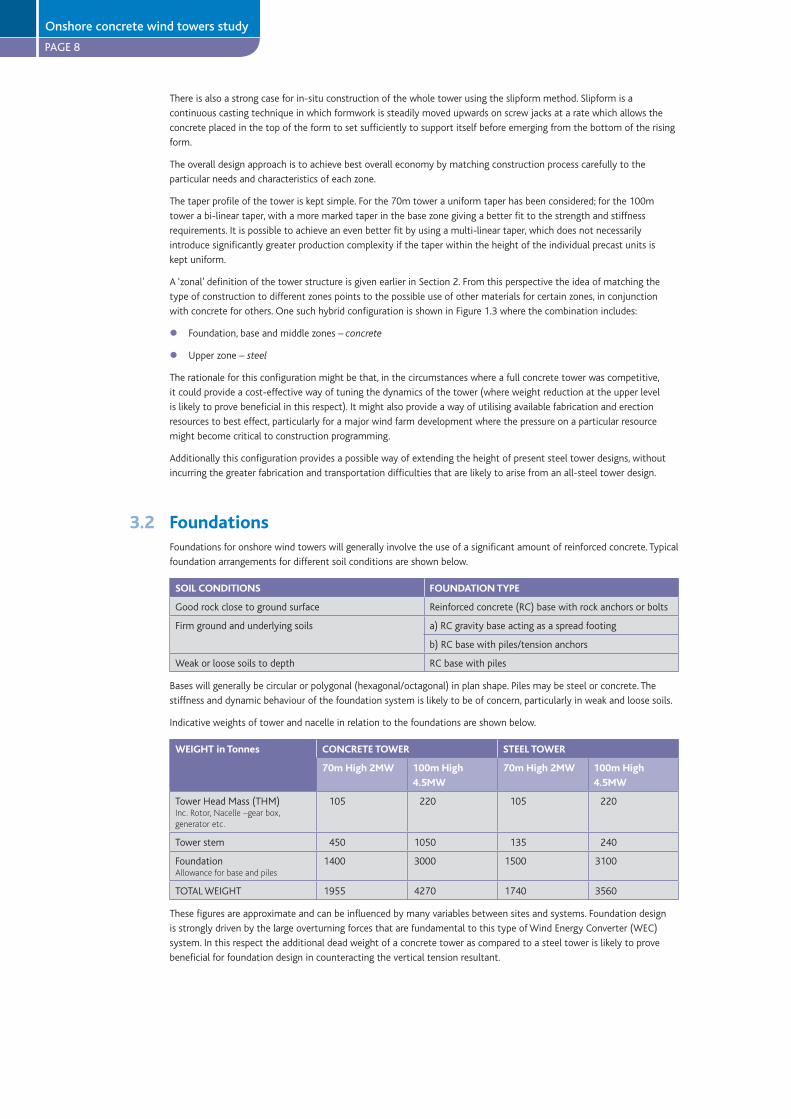
3.2 FoundationsFoundations for onshore wind towers will generally involve the use of a significant amount of reinforced concrete. Typical
foundation arrangements for different soil conditions are shown below.
SOIL CONDITIONS FOUNDATION TYPE
Good rock close to ground surface Reinforced concrete (RC) base with rock anchors or bolts
Firm ground and underlying soils a) RC gravity base acting as a spread footing
b) RC base with piles/tension anchors
Weak or loose soils to depth RC base with piles
Bases will generally be circular or polygonal (hexagonal/octagonal) in plan shape. Piles may be steel or concrete. The
stiffness and dynamic behaviour of the foundation system is likely to be of concern, particularly in weak and loose soils.
Indicative weights of tower and nacelle in relation to the foundations are shown below.
WEIGHT in Tonnes CONCRETE TOWER STEEL TOWER
70m High 2MW 100m High
4.5MW
70m High 2MW 100m High
4.5MW
Tower Head Mass (THM) 105 220 105 220
Tower stem 450 1050 135 240
Foundation 1400 3000 1500 3100
TOTAL WEIGHT 1955 4270 1740 3560
These figures are approximate and can be influenced by many variables between sites and systems. Foundation design
is strongly driven by the large overturning forces that are fundamental to this type of Wind Energy Converter (WEC)
system. In this respect the additional dead weight of a concrete tower as compared to a steel tower is likely to prove
beneficial for foundation design in counteracting the vertical tension resultant.
l
l
Onshore concrete wind towers study
PAGE 9
3.3 Tower elementsThe tower shaft may be split into a number of different sections for the purposes of strength and stiffness design,
fabrication and erection. The possible types of construction featured in this study and their likely zonal application
have been indicated in Section 3.1. This shows how various combinations of in-situ, precast, and hybrid concrete/steel
construction might be applied, thereby allowing optimisation for different physical and development circumstances.
The use of precast concrete units for all three zones of the main shaft is an important option. A possible outline
arrangement for such units is shown in Figures 1.4 and 1.5 for 70m and 100m high towers respectively.
The units may comprise a number of segments (2, 3 or more) to complete a ring, or whole ring units (cast as one unit)
according to the ring section diameter and to the weight of individual units, all to take account of ease of transportation
and handling. The wall thickness of units/ring sections may be varied between different zones and possibly within the
separate zones. Similarly, concrete strength may be varied to achieve an optimum balance between the various cost
drivers and physical constraints.
The construction sequence for an all-precast tower as shown in Figure 1.6 is described further in Section 3.7.
3.3.1 Base zone
Generally in-situ concrete is required for foundation construction (Section 3.2). The construction of the base zone of
the tower using in-situ concrete would not require the deployment of substantially different resources, apart from the
particular formwork system for the base zone of the tower shell. Wall thicknesses typically in the range of 350-400mm
plus would be vertically prestressed. This wall thickness is needed for strength. Thickening the wall even further in this
zone may provide an efficient way of tuning up the overall tower stiffness since, amongst other things, the additional
mass here has very little effect on the natural frequency of the structure and can in fact provide a useful added
compressive load on the foundation.
Prestressing tendons could be accommodated within the wall thickness if desired and as such could be either bonded or
unbonded. The overall construction operations have quite similar logistics and do not incur heavy additional costs in this
respect.
Alternatively, the use of thick walled (300-400mm) precast concrete segments can provide a solution. These would be
conditioned in size for transport to the site, and might have a width of 3-3.5m and a length (height when erected) of
12-18m. They would probably be best erected in-place before joining with in-situ poured concrete stitches to form a
monolithic ring shell. Such joints could be conveniently made as wide joints, with projecting reinforcement from the
precast units interlocking within the joints.
In either case the base zone construction in concrete can easily accommodate the local details (doorway etc.) for access
to the tower. The design can be easily adapted to provide the base support to an upper steel tower as a hybrid solution.
A hybrid design may offer an immediately attractive solution for those projects with towers above 80-90m height, which
are already essentially committed to the use of steel towers. Such an approach could avoid the step change in steel
plate thickness required for the shell in the base zone, and thereby avoid the additional fabrication and transportation
difficulties that may be experienced with the use of the heavy large diameter steel tower shells for such towers.
3.3.2 Middle zone
Weight minimisation of the middle zone upwards is key to achieving a cost-competitive solution for a full-height
concrete tower design.
For a given outline profile of the tower, the direct variables affecting the weight of the tower shell are effective concrete
density (i.e. the density of the concrete reinforcement composite) and wall thickness. For the present study the use of
lightweight concrete (using special manufactured aggregates) has not been considered in any depth. The unit weight
(density) of concrete considered for structural design purposes is relatively independent of strength and for present
purposes has been taken as 24 kN/m3, which is typically used for reinforced concrete with moderate levels of steel bar
reinforcement.
The wall thickness is taken to be uniform for individual units (except locally at prestressing tendon anchorage points on
certain units only). Various drivers include structural strength, stiffness, local stability and durability requirements which
define minimum concrete cover to steel reinforcements or otherwise unprotected steel prestressing ducts and strand.
In the middle zone upwards the minimum wall thickness may be determined by the ‘concrete cover to reinforcement’
requirement rather than by the necessary strength and stiffness. This becomes more critical as the design strength class
of the concrete is increased.
It is considered that even by using only a single centrally placed layer (two-way grid) of normal steel rebar, but taking
account of realistic placement tolerance even with factory production, it will not be practicable to achieve sufficiently
reliable durability for a long life tower structure (50 years plus) in an aggressive external environment with a wall
thickness of less than 150 to 175mm.
Onshore concrete wind towers study
PAGE 10
Overcoming the restrictions imposed by the normal concrete cover requirement allows the use of thinner concrete walls.
This could be important to the minimisation of the weight of the middle and upper zones of the tower and the cost of
the tower overall.
Various techniques are available which can overcome these restrictions. These are discussed further, along with a possible
design solution, in Section 3.5.
3.3.3 Upper zone
The design logic of weight minimisation could be even more relevant to the upper zone. It is envisaged that the thinnest
practicable shell elements will be used here, subject of course to the provision of sufficient resistance to the maximum
cyclic wind effects. For present purposes the minimum wall thickness has been set at 100mm.
The top of the tower has to support the turbine nacelle and yawing bearing. For present purposes it is considered that
this connection will be provided by means of a ‘turbine spur’. Notionally this will be a two metre high section of steel
shell matching the out tower profile, within which there is a transfer platform supporting the yaw ring, and through
which there is a central access hatchway into the nacelle. This fabrication would be fixed to the head of the concrete
tower by a ring of stressed bolts.
3.4 Prestressing of the towerThe concrete tower is designed as a vertically prestressed tapering tube. A circumferentially uniform pattern of
prestressing forces is to be applied at a magnitude which changes with height (in a stepped pattern) according to the
forces that the tower has to resist. This will provide a circumferentially uniform vertical compressive stress sufficient to
avoid vertical tensile stresses in the tube walls under normal design loading. This vertical prestress is also important to
the shear strength of the tower tube.
Prestressing provides an efficient and economic means of achieving good all round strength with excellent durability,
fatigue and dynamic performance. It also provides a straightforward and positive means of unifying the separate rings
of a precast concrete solution so that they act as a monolithic tower structure. With careful design and detailing,
prestressing can also provide solutions to the problems of handling units for erection and maintaining adequate strength
in the partially completed tower during its construction. This can be further appreciated by reference to Section 3.7 and
Figures 1.6 to 1.8.
The choice of general technique and configuration lies between bonded and unbonded tendons, and internal or external
placement. In general, unbonded external tendons are favoured in this onshore study for their simplicity and ease of
installation although bonded or unbonded internal tendons could also provide a satisfactory solution, particularly for the
thicker sections of wall and especially in the base zone.
External prestressing involves the placement of the prestressing tendons (cable or bars) outside the structural section
which is to be prestressed, and therefore removes the need to accommodate the tendons and any ducts within the
thickness of the shell wall. The stressing force is imposed through an anchorage detail that transmits it back into the
section. An anchorage is of course required at each end of the tendon. The tendon is not continuously bonded to the
section in question although it may be restrained back to it at discrete points along its length. In the case of the tower,
vertical prestressing of the tower shell may be applied by a circular array of tendons placed within the concrete tower
shell close to its inside face.
Crucially the use of external prestressing permits the use of thin-walled concrete sections for the tower, since wall
thickness is not governed by the need to accommodate tendons internally. Another important advantage is that
installation of the tendons at the various stages of construction can be more easily achieved.
It might be argued that the external prestressing tendons will be more at risk from corrosion. There is long experience
of the use of external tendons on major bridge structures. Whilst care always has to be taken to ensure the durability
of highly stressed components, particularly in the anchorage areas, there is no reason to think that this represents
an unusual or insolvable problem. The tendons would be protected by factory installed corrosion protection systems,
including inhibitors, greasing and heavy plastic sheathing. Anchorage areas will be accessible for proper finishing, capping
and inhibiting grease injection. Additionally, unlike internally located prestressing strands, the external tendons would be
visible, easily inspected and even replaceable. Location within the internal tower shaft provides a sheltered and relatively
benign environment within which humidity and condensation could be actively and economically controlled as a further
precaution.
There are further advantages from using external unbonded prestressing. There will be even higher fatigue tolerance of
dynamic loading because the cables will experience an overall averaged and therefore lower stress range during load
cycling, as compared with bonded cables which are subjected to rather higher more localized stresses. There will also
be lower friction losses during stressing. The eventual demolition of the structure will be simplified, and the recovery of
both the concrete and steel component materials for recycling will be simpler and cheaper.
Outline details for cable layout, anchorage and restraint are shown in Figures 1.6 and 1.8.
Onshore concrete wind towers study

PAGE 11
It is considered that some restraint of the individual unbonded tendons is required, linking them back to the tower
shell. Figure 1.10 shows a simple detail that would provide such restraint. This restraint would provide some additional
stability to the tower under accidental overload or high level impact as might occur during erection. It would also act as
a safety measure during construction by restraining any whiplash movement should a tendon inadvertently fail due to
overstressing during the stressing operation.
3.5 Thin walled shell unitsThe importance of minimising wall thickness to the economy of the concrete tower design has been discussed in Sections
3.3.2-3. This is particularly important when cranage is needed to lift large units into place. For a vertical direct load and
/or overturning bending capacity, the tube wall thickness can be reduced by increasing the concrete strength class (it is
considered practicable to increase this up to a compressive strength of 100N/mm2 as required, and possibly beyond).
However there are limitations to the minimum thickness of conventionally reinforced concrete sections due to the
need to provide a minimum thickness of concrete cover as explained in 3.3.2 and possibly from the accommodation of
prestressing tendons. An approach to overcoming the latter limitation has been set out in Section 3.4. The concrete cover
restriction may be overcome by the use of non-corroding reinforcement.
Some possible techniques and ways that these might be used are explained below:
i) The use of non-corroding reinforcement would remove the need for thick cover (50-75mm) required for external
or aggressive environments, and would allow cover thickness to be reduced to dimensions necessary to allow good
penetration and compaction of the concrete around the reinforcement, and provide good bond strength and transfer
of forces from the reinforcement into the body of the concrete. By limiting rebar diameters to small to medium range
(10-25mm dia) cover dimensions could be reduced to 25mm assuming that the durability issue had been overcome.
Assuming the use of steel rebar, the options are epoxy coated, galvanized or stainless steel rebar. Both the coated
bars (epoxy/galvanized) are susceptible to mechanical damage or local weakness of coating, and to consequential
anodic corrosion which could limit their durability and reliability for long life structures. For the present study it is
assumed that stainless steel rebar will be used where steel reinforcement is required in thin wall situations, or in
other details where low cover is desirable or necessary for design reasons. It is generally accepted that stainless steel
rebar can be used in conjunction and in contact with normal steel reinforcement within concrete members without
any serious risk of ‘cathodic/bi-metallic’ corrosion problems.
It is important to note that stainless steel costs approximately five times more, weight for weight, than normal high
tensile steel rebar. It is therefore vital to limit the use of such reinforcement to a minimum in order to achieve the
potential economy of thinner walled sections.
ii) Other techniques for achieving non-corroding reinforcement include the use of non-ferrous reinforcement in an
analogous way to conventional steel reinforcement or by using significant quantities of chopped fibre as part of the
concrete matrix. The former approach has not been considered any further here as such reinforcements are not in
widespread current use with concrete and do not appear to offer significant overall advantages at present.
On the other hand the use of chopped fibre reinforcement concrete (FRC) is being widely used in various applications.
Techniques and supply arrangements are well established with a significant international research effort continuing to
achieve improved structural properties and performance for FRC. Suitable chopped fibre materials are certain polymers
(polyesters/polypropylenes), stainless steel wire or arguably even normal steel wire. Fibre reinforcement can give
considerably increased resistance to cracking and much greater toughness over plain concrete. At present FRC cannot
be relied upon to provide reliable tensile strength to resist major primary structural actions.
The question arises as to what strength characteristics are needed for the concrete tower shell? The tubular form
provides excellent vertical load carrying capacity and there is no primary need for tensile reinforcement for this purpose.
Overturning bending of the tower will be resisted by the action of the prestressed concrete tube, as will horizontal
shear and torsion forces about the vertical axis. Bending in the wall shell about the vertical axis and associated shear
forces, and horizontal hoop forces, are generally likely to be very small from externally imposed forces. Such forces, to
the extent that they are significant, are likely to be the result of strain induced loads from temperature, creep etc. It
is considered that these secondary effects can be resisted safely by local reinforcement and the provision of a level of
general toughness and crack resistance.
The effects of loadings from the turbine at the very top of the tower, particularly cyclic loadings, may require wall
thicknesses greater than the minimum achievable. However moving down and away from the uppermost level, the stress
levels from these loads will drop with the increasing section diameter, and may provide a zone of tower where these
walled units provide an appropriate economical and useful design solution.
By combining the use of limited quantities of stainless steel reinforcement with the use of FRC it is considered that thin-
walled shell units with the necessary structural properties can be economically constructed.
Fibre reinforcement is proposed as the most suitable material for alternative concrete reinforcement. Fibre reinforcement
is to be used throughout the precast ring segments, but with all the steel reinforcement omitted over the central region
Onshore concrete wind towers study
PAGE 12
of the rings. The prestressed design of the concrete tower ensures that for ultimate limit states, no tension occurs in the
concrete. Consequently the fibre reinforcement provides some general toughness and resistance to secondary effects
such as thermal stresses. Bands of stainless steel reinforced concrete are located at the ends of each ring segment to
provide extra toughness during lifting and handling and act as ‘crack stops’ down the tower. Figures 1.7 – 1.10 show the
arrangement for a typical ring segment.
It must be emphasised that while this approach uses existing concrete technology to its limits, in essence nothing new
is being proposed. The materials are well proven for the functions they perform. However, this approach could play an
important part in achieving a precast concrete solution that can be both cost competitive and able to challenge the
current steel solution.
3.6 JointsThese comments apply to the precast concrete solution or possibly to the joint between an in-situ concrete base and a
precast middle/ upper section of tower.
Simplicity of connection and accuracy (and trueness) of level are the two key drivers for joint design. The simplicity of
the connection will keep the formwork costs and on-site construction time to a minimum. Accuracy of level across the
top of the joints is imperative in order to ensure verticality of the final complete tower.
Two basic types of joint are envisaged. One will be at a connection of the precast units where the prestressing strands
terminate, the other will be at an intermediate connection of the precast units where the prestressing tendons are
possibly linked to the tower wall but not terminated.
The joints will be provided with a simple mechanical connection such as stainless steel dowels to facilitate accurate
engagement and assembly, to fix each unit’s location immediately after placement and before overall prestress is applied.
This takes account of the possibility that prestressing may not be applied until several units have been stacked up.
One possible concept for achieving a self-levelling joint involves the use of three local seating pads on each side of
the joint to ensure verticality to within a few millimetres. The seating pads are envisaged as thin projections above the
general joint surface that would be ground to a precise level to set the general thickness of the joint. The thin joint will
be filled with epoxy resin. The method of application of the resin would need to be carefully developed to be weather
tolerant and reliable. It may involve such techniques as injection or pre-placed mortar/ resin pre-placed impregnated
tapes. Some of the stainless steel dowels would be made longer to act as locators to facilitate rapid acquisition and
correct orientation of the incoming unit, and achieve fast connection of the joints in the difficult conditions on site.
It is important that simple jointing and connection methods are devised to facilitate straightforward and rapid erection.
Indicative details are illustrated in Figures 1.7–1.10. These details are based on the use as far as possible of plain thin epoxy
joints between units, with the units coupled vertically both individually and overall by prestressed bolting and tendons.
3.7 Construction sequenceA notional construction sequence for a precast concrete tower is illustrated in Figure 1.6.
The precast units will be transported to site as whole rings for smaller diameter sections and as ring segments for the
larger diameter rings. Ring segments will be joined into a complete ring on site. Ring sections will be stacked up, either
in place for the lowest heaviest rings, or into tower sections comprising three or four rings for lifting into place on the
tower. Some limited stressing together of tower sections prior to lifting into place may be useful to assist with handling,
or alternatively a special lifting cradle may provide a quicker and more cost-effective solution.
Newly erected sections of the tower would be stressed either by bolts/tendons connected to the underlying section,
or by full length tendons emanating from the base anchorage. This would provide both the short term stability during
construction and contribute to the permanent works strength. The aim would be to achieve an efficient pattern of
curtailment of tendons and consequently applied prestress which was well matched to the design envelope of externally
applied force resultants.
This approach to prestressing requires anchorage arrangements at a number of levels over the height of the tower. Figure
1.8 indicates a possible outline detail involving the provision of an annular ring beam formed inside the tower shell on
selected units. The ring beam would contain vertical duct holes at regular spacing around the perimeter set to align with
the planned tendon paths. This detail could provide anchorage to long tendons, short bolts, or act as a local duct for
tendons continuing up the tower. The ring beam would require relatively heavy local reinforcement in accordance with
normal practice for prestressing anchorages. This would probably be best provided by stainless steel bars in the form
of welded cages, allowing cover to be minimised and thereby reducing the propensity for cracking and also of course
minimising the additional weight of the ring beam.
The number of tendons, curtailment pattern, anchorage positioning, and so on are interlinked with the requirements for
erection and construction as well as those for the permanent design. Careful design and planning at all levels of detail
will be an essential part of producing an efficient and cost-competitive solution.
Onshore concrete wind towers study
PAGE 13
3.8 In-situ slipform constructionPrecast concrete units offer a viable design solution for the whole tower, and also for the middle and top zones in
combination with an in-situ concrete, slipformed base zone. Alternatively, in-situ slipformed construction for the entire
pylon height offers some potential advantages, avoiding the need for transporting precast units to the wind farm
site and the provision of heavy cranage. This could be particularly useful for sites in areas where access for very large
vehicles is problematic. Whilst in-situ operations clearly involve the transportation of basic materials to site, this can be
undertaken off critical timelines and does not pose special problems of vehicle size or load size. State-of-the-art mixing
equipment such as volumetric truck mixers or mobile site plant can be easily used to deliver high quality concrete on
site.
Minimum wall thicknesses, achievable without incurring special difficulties, are in the range of 150–175mm. Below
this thickness, proneness to horizontal cracks due to slipform drag may become a problem. Certain minimum levels
of steel reinforcement are also required to provide the necessary early support and strength. Thus the ‘thin shell’
concepts described in Section 3.5 do not apply to the same extent to in-situ slipforming. In general this is not likely
to be a significant source of diseconomy, since cost and productivity considerations of heavy cranage do not apply to
slipforming.
With regard to productivity and programme time, slipforming, by its nature, is a continuous 24/7 operation with output
rates of four to six metre heights per day routinely achievable.
3.9 Cranage and liftingA current feature of wind farm construction is the deployment of heavy long jib cranes to handle and assemble the
large and heavy components or units. This may involve lifting from the transporter for preassembling of sub-units on
the ground, and then lifting assembled units from the ground, or lifting direct from the transporter into place on the
foundation or partly constructed tower. Such cranage is expensive, particularly if there are delays due to weather, supply
or assembly problems.
Slipforming illustrates a technique which removes the need for cranage, at least for the tower construction itself. At
present it would nevertheless be necessary to deploy a heavy crane for lifting the yaw ring/ nacelle/ generator and the
turbine rotor either completely separately, or in a ‘bunny ears’ configuration with the nacelle.
A fundamental feature of slipformed tower construction is the use of the existing tower to provide the main load path
to ground for the raising of the new construction. The tower also provides the main stabilizer/ lateral strength for the
man/ materials lift mast. This approach, using the partly constructed tower as a major component of the ‘temporary
works’, provides a possible pathway to greater economy and construction simplicity for the future, whether for lifting
precast concrete units, nacelles or others.
It would be interesting to speculate on the form of devices using this approach. It is perhaps useful to note that there
are features of a concrete tower that would seem to give greater scope and facility for accommodating such devices,
compared to a steel tower. The greater wall thickness of the concrete tower can more easily accommodate the
imposition of high local wheel or clamping loads, whilst the provision of embedded fixings for track-ways or masts are
also less likely to cause stress raiser or notching problems, which could adversely affect fatigue strength and durability.
3.10 Structural analysisThe ultimate strength of the tower was determined from the loading at the turbine’s maximum operating wind speed.
The extreme design bending moment at the base of the 70m tall tower is 70,000 kNm and for the 100m tall tower is
210,000 kNm both with a load factor of 1.5.
The dynamics of the tower were assessed by calculating the natural frequency of the tower and comparing this to the
1P-range (single blade passing frequency). The range for the first natural frequency of the towers was found to be 0.4Hz
to 0.8Hz for the 70m high tower, and 0.3Hz to 0.7 Hz for the 100m high tower, encompassing the variability of soil
stiffness, concrete stiffness and turbine mass likely. This is similar to other such towers for wind energy converters. The
dynamic load inputs into tower structures depend upon the characteristics of both the rotor/ generator characteristics,
the tower/ foundation structural system characteristics and their interaction.
Within the ‘turbine’ system there are many variables under the manufacturer’s control, including active control/
management algorithms, which affect its behaviour of, and therefore inputs into, the overall structural system.
At general concept stage it is not possible to take full or precise account of all this complexity, although a range of
representative values for the major load effects have been considered. It is believed that prestressed concrete towers,
particularly in the middle/ lower tower zones, will be less sensitive than steel towers in their critical design sizing to the
variations between different turbines of similar rating. Exploring and determining this sensitivity is an important part of
the next stage of work in developing economic concrete designs.
Onshore concrete wind towers study
PAGE 14
There is ample scope to tune the towers’ dynamic performance both during design and during commissioning. During
design the Young’s modulus of the concrete, the foundation and in-situ base section geometry and mass, and the mass
at the top of the tower can all be varied to produce the desired dynamic performance for the tower. Once constructed
the mass at the top of the tower can be altered to tune the tower based on as-built testing. This might be useful during
prototype development. The use of mass damping at the top of the tower in the turbine would also allow the dynamic
performance of the tower to be tuned.
This ability to tune the dynamic performance of concrete towers, including the ability to tune the tower during
operation, reduces the potential risk of adverse dynamic behaviour of the tower. It ensures that the concrete tower
solution can be designed to avoid interference with the 1P-range and can be tuned to individual site constraints.
An assessment of the potential fatigue damage to the tower design over a 25 year design life was also carried out, with
concrete performing favourably.
4 QUANTITIES AND COSTS
The early estimation of costs of innovative design solutions is often very difficult as, by the nature of the situation, little
direct data is available to the designer. It requires considerable engineering design, construction and logistics planning
to get to a point where high levels of assurance can be given on cost estimates. In the case of wind energy much of the
commercial and detailed construction cost information is held by the wind turbine companies and to some extent the
wind farm developers. It is understandably regarded as intellectual property which is carefully guarded and, if available at
all, such information is usually very general with limited contextual supporting information. In this study we have based
our judgement of costs on basic and comparative cost exercises using estimated quantities of the main constituent
materials coupled with unit rates adjusted for the adverse or advantageous factors that are judged appropriate.
The costing exercise was undertaken on the two demonstration all-concrete design solutions (70m tall tower and 100m
tall tower). Costs were calculated based on a worked-up cost per tonne for the installed tower (excluding foundations
and turbine) of around £580/te to £600/te, and using the tower weights detailed in Section 3.2. Comparisons with
estimated costs for equivalent 100m and 70m tall steel tower show that the demonstration concrete tower designs are
at least cost competitive, with potential cost savings of up to 30%. In this respect it is considered that slipformed towers
provide the greatest potential savings. These savings are postulated on the basis of a substantial design development
process coupled with the construction and testing of some prototypical towers. They also assume that reasonable
economies of scale are available from the size of the individual development projects and from some continuity on key
features of the design between projects.
5 ONSHORE STUDY CONCLUSIONS
The contribution of wind energy to the UK’s supply of electricity is planned to grow substantially over the next
decade, with the number and size of wind farm projects in process and being commissioned now starting to rise in
line with these plans. Therefore the demand for turbine towers is also rising in both numbers and size.
The wind turbine industry is looking for better solutions for tall wind turbine towers of 100m or more in height.
This is being driven partially by the imminent release of a new generation of larger wind turbines with longer blades,
as well as the reduction in the availability of unexploited ‘favourably windy’ sites which will drive the need to exploit
less windy sites, with less advantageous topography.
100m tall towers are at the limit of existing steel designs and the installed fabrication technology needed to
produce them. They also present serious difficulties for transportation of the lower steel sections for the taller
towers.
The trends towards increased size of turbines (rating, weight), tower height and therefore diameter and weight, and
to larger wind farms all provide more favourable competitive opportunities for concrete towers.
Concrete towers (100m plus height) have been used successfully elsewhere in Europe, particularly in Germany. These
have featured both precast and in-situ slipformed designs, similar in general terms to some of the design options
considered in this study.
All the designs considered in this report involve the use of vertical prestressing. Various configurations, techniques
and details have been proposed, based upon the existing state of the art.
In order to achieve sufficiently competitive full height solutions which seriously challenge onshore steel tower
designs in the UK, substantial design and development effort to optimise concrete designs is needed.
l
l
l
l
l
l
l
Onshore concrete wind towers study
PAGE 15
Key issues for attention are minimising material content and structural weight, particularly in the middle and upper
zones of the tower, whilst achieving construction simplicity with short construction times. Concrete technology and
the material itself offer great flexibility for optimising the design solution for particular circumstances.
Useful weight and cost savings in the middle and upper zones of the tower may be available from some
development in the use of fibre reinforcement, as suggested in the report.
The use of in-situ slipform construction methods provide an efficient way of overcoming the difficulties of
transporting large tower rings/sections to site, and removes the need for the use of a large crane for the tower
erection.
The development of ‘craneless’ methods for the erection of the turbine (rotor) nacelle and rotor using lifting
platforms climbing up the tower itself could offer further important overall economies. The concrete tower shell is
well suited to supporting local concentrated loads that would be imposed by such devices.
The design philosophy presented draws on concrete’s flexibility and promotes an approach to a solution that can be
adapted to suit the individual demands of each wind farm development, and thereby provide a more cost-effective
outcome. The use of precast concrete, in-situ concrete and steel in various composite or hybrid configurations is
allowed for.
Exploitation of the durability and longer fatigue life of prestressed concrete towers could provide greater
sustainability and long term economic benefits. With the tower service life extended to between 40 and 60 years,
one or more turbine re-fit cycles could take place with minimal further expenditure on the tower, foundations and
other infrastructure.
Concrete solutions for a 70m and 100m tall tower are derived from the design philosophy. They show cost
competitiveness with likely equivalent steel solutions. Costings indicate that there is a potential for savings of up to
30% over steel towers for taller towers (70-120m plus) supporting larger turbines.
6 FIGURES - ONSHORE WIND TOWERS
Figure No.
1.1 70m CONCRETE TOWER - Outline and indicative dimensions
1.2 100m CONCRETE TOWER - Outline and indicative dimensions
1.3 HYBRID TOWER - Arrangement with steel upper section
1.4 70m CONCRETE TOWER - Assembly from precast concrete units
1.5 100m CONCRETE TOWER - Assembly from precast concrete units
1.6 TOWER CONSTRUCTION SEQUENCE
1.7 ASSEMBLY OF RING UNITS INTO TOWER SECTIONS
1.8 TOWER SECTION JOINTS - Anchorage section and plain joints
1.9 RING UNITS - Reinforcement and segment joints
1.10 TENDON RESTRAINTS - Yokes to plain units
l
l
l
l
l
l
l
Onshore concrete wind towers study

PAGE 16
Figure 1.170m CONCRETE TOWER -
Onshore - figures
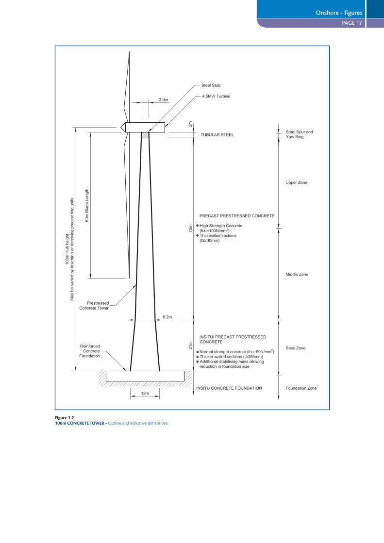
PAGE 17
Figure 1.2100m CONCRETE TOWER -
Onshore - figures
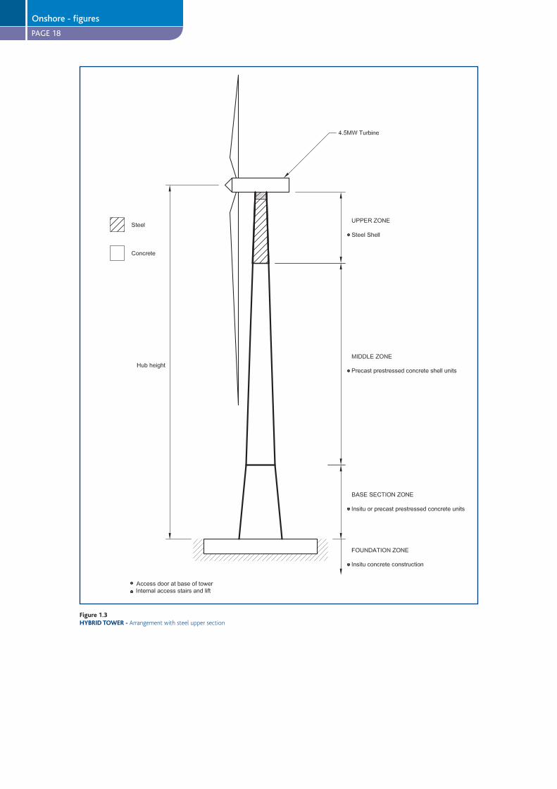
PAGE 18
Figure 1.3HYBRID TOWER -
Onshore - figures
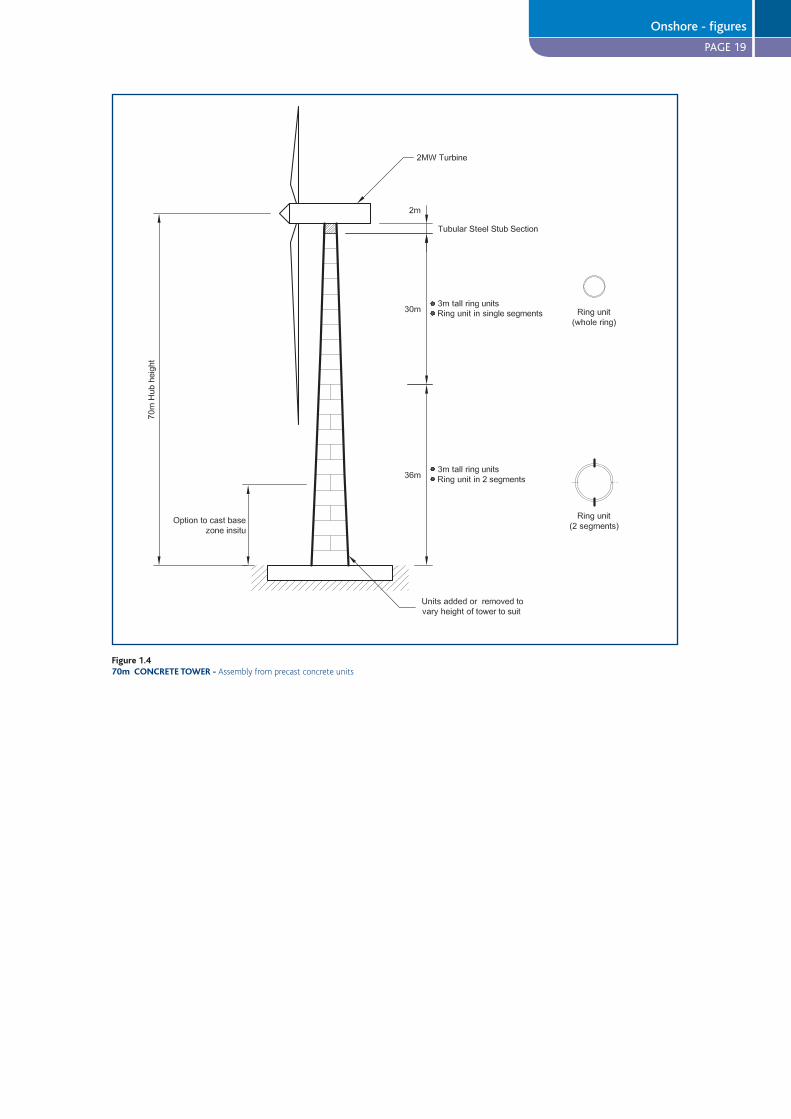
PAGE 19
Figure 1.470m CONCRETE TOWER -
Onshore - figures
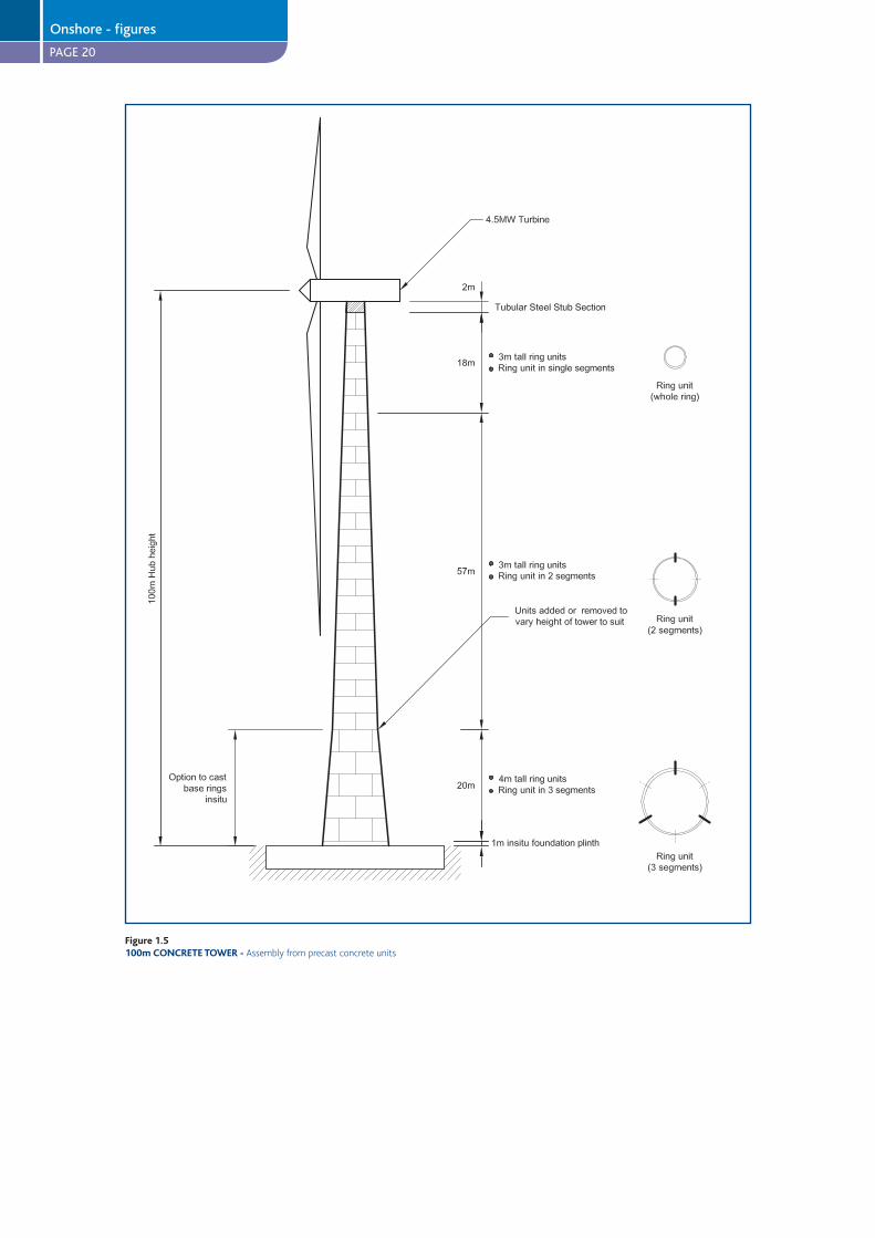
PAGE 20
Figure 1.5100m CONCRETE TOWER -
Onshore - figures

PAGE 21
Figure 1.6TOWER CONSTRUCTION SEQUENCE
Onshore - figures
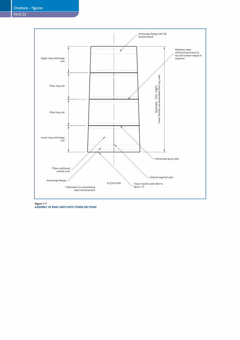
PAGE 22
Figure 1.7ASSEMBLY OF RING UNITS INTO TOWER SECTIONS
Onshore - figures
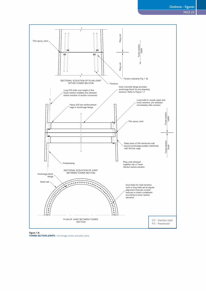
PAGE 23
0
7F
Figure 1.8TOWER SECTION JOINTS -
Onshore - figures

PAGE 24
Figure 1.9RING UNITS -
Onshore - figures
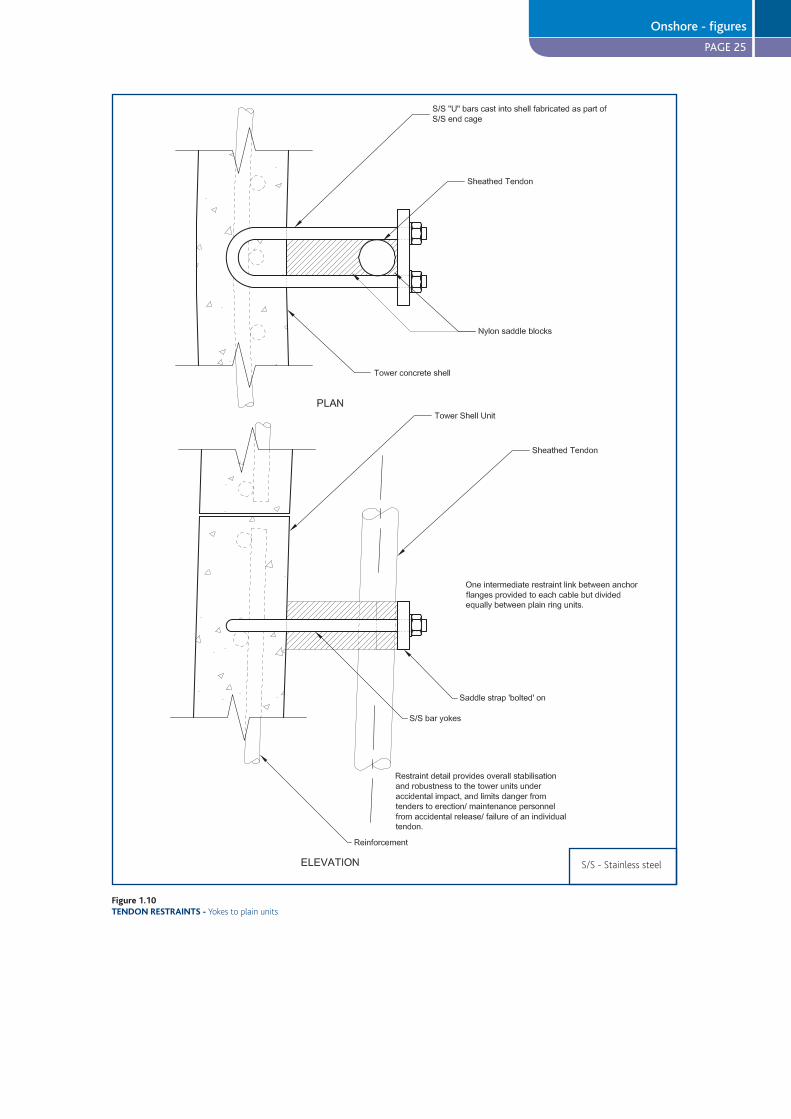
PAGE 25
Figure 1.10TENDON RESTRAINTS -
Onshore - figures

PAGE 26
STUDY OF CONCRETE TOWERS FOR OFFSHORE WIND FARMS
This study was undertaken before the work on onshore wind farms. Some of the concepts touched on in this section have already been covered, particularly in relation to the design of a lighter weight pylon. Readers are advised to read both the onshore and offshore studies in order to get the fullest information from this report.
7 DESIGN PHILOSOPHY
7.1 Design drivers and approachThis section focuses on producing a design solution for offshore wind farms. The design scenarios considered make
some allowance for the larger turbines and taller towers that are being developed to meet current trends. The aim is to
illustrate that the conceptual concrete designs proposed are adaptable to both present and future industry needs.
Design drivers include:
The size of turbines and rotors is increasing, demanding increased tower height, strength and stiffness.
Offshore towers have to resist significant wave and wind loadings during storm conditions.
Blade rotation leads to cyclic loading of both the blades themselves and the overall tower structure. Wave loading
on the tower pylon also involves a high number of cycles with some regularity in frequency. Fatigue effects and
tower resonance may both strongly affect design.
Competitive and economic design requires simplicity of form and detail allied to a basically competitive technology.
Aggressive marine environments require durable materials and details.
Offshore operations are difficult, expensive and weather prone. Careful planning and design are required for ease
and speed of erection and completion. Low maintenance and straightforward decommissioning are also important.
Limited availability of offshore heavy lifting plant and the limited offshore construction season needs to be
considered in design.
For greatest economy, large scale production utilising production-engineered design is needed.
Life cycle issues are especially important for renewable energy systems. During initial design stages, general
consideration has to be given to buildability - including fabrication, transportation and erection - based on current
capabilities and practice. Reversal of the construction process to allow for eventual removal and disposal at the end of
the tower’s operational life must also be considered. These issues have been given considerable thought when developing
the indicative designs.
7.2 Design scenarios and criteriaA generic scenario has been selected as a basis for preparation of trial designs. This is shown in Figure 2.1 and is intended
to provide a reasonably representative but demanding test of both the present and future applicability of concrete
designs for offshore applications.
Tower hub heights of both 80m and 100m above lowest astronomical tide (LAT) are considered in order to represent
both common current practice and the tallest offshore wind towers likely to be constructed in the next 10 years.
A water depth of 25m (from LAT) is chosen. This is based on an assessment of all UK Round 2 wind farm sites . Being at
the deeper end of the range, 25m has been chosen to meet future as well as current demand.
The scenario is based on the trend of increasing generator sizes, which demand large rotor diameters and tower heights.
It is anticipated that construction in water depths greater than those typical of the first generation offshore sites is likely
to become necessary over the next decade as the availability of further shallow water sites diminishes, putting more
importance on harvesting energy from sites that are currently less economic to exploit.
l
l
l
l
l
l
l
l
Offshore concrete wind towers study
PAGE 27
These further design criteria were applied for preliminary design purposes:
A design life for the structure of 20 years and a return period for extreme storm events of 50 years were chosen,
conforming to current practice.
The critical design condition is the extreme storm event.
Wave loading, wind loading and turbine loads are included. Wave induced/tidal current loads have not been
considered since they are negligible compared to the extreme wave loading. A 3MW turbine is selected as the
reference design case, as it is in the upper range of turbine capacity currently available. A commonly used turbine
model has been considered, and the manufacturer’s design loads have been used for the study.
In accordance with the Intergovernmental Panel on Climate Change, expected sea level rise is taken as 0.005m per
year, which is negligible for the purposes of this study. The effect of climate change on storms and on the recurrence
of extreme values of wind speeds or wave height has not been considered for present design purposes.
An allowance of two metres for seabed level changes (from scour, etc.) is included. Highest astronomical tide (HAT)
is taken as 3.8m above mean water level, with an allowance for storm surge of 1m on top of HAT.
An extreme wave height of 12m and wave period of 10 seconds are selected.
8 DESIGN
8.1 Tower configurationFor offshore situations, wind towers may be conveniently defined as having two distinct sections, namely:
The pylon – from the nacelle to the level of the highest wave crest
The foundation and substructure – everything below the pylon
Pylons experience substantial horizontal loads imposed from wind, through the operating turbine and directly on the
tower stem. Additionally the substructure and foundations are subjected to larger horizontal forces from waves and
possibly vessels. In comparison with structural forces imposed by turbine and pylon loads, the overturning moments
imposed at foundation level by wave, and vessel loading in deep water sites (20-30m) are virtually an order of
magnitude larger.
For deep water sites, it is likely that spread foundations – gravity or piled caisson, or tripod – rather than monopile, will
best provide the required dynamic and structural characteristics. Caisson structures can be designed to be self-buoyant
for tow-out and installation and, therefore, minimisation of self weight is not critical. Indeed, in such instances additional
mass may be advantageous for stability. Nevertheless, it is important to consider limiting the mass of the material in the
design for the sake of economy.
On the other hand, construction of pylons onshore with subsequent installation offshore might involve the use of
cranage to lift large pylon segments. Minimisation of the pylon self weight will be important using such methods. The
distribution of mass over the height of a pylon is also important as this is likely to contribute significantly to its dynamic
response. This may need to be tuned in relation to the overall dynamic characteristics of the foundation/pylon system.
8.2 PylonA tapering hollow cylinder has been selected as the structural configuration of the main wind tower pylon. Recently
constructed wind energy towers, both onshore and offshore, have predominantly used this simple and elegant form. It
provides both an efficient structural member and an aesthetically pleasing appearance and, as such, is an appropriate
starting point for this design exercise.
Variants on the tapering tube structure, or even perhaps some other form, might offer some potential improvements in
efficiency, particularly in terms of specific strength or stiffness (i.e. strength or stiffness per unit weight of structure).
l
l
l
l
l
l
l
l
Offshore concrete wind towers study

PAGE 28
8.3 Foundation and substructureGround conditions are likely to vary considerably between different sites. Other site conditions may also vary, including
water depths. In combination, the variations may demand a range of different foundation types and designs. To take
some account of this, the study looked at two different solutions for concrete pylon foundations: a concrete gravity
foundation and a steel monopile with a grouted concrete stem.
The concrete gravity foundation considered is a caisson filled with ballast or rock. The caisson would be circular or
polygonal in plan. This is a tried and tested solution for underwater foundations which is potentially simple and for which
there is a range of possible installation methods.
Where surface sea bed strata have sufficient strength, caissons can transfer loads through direct bearing. Alternatively,
caissons could be piled for weaker underlying ground conditions, to increase the strength and stiffness of the foundation
as necessary. The caisson would be set down on a prepared bed - usually comprising a levelled stone blanket. Typically
the caisson may have a down-standing skirt or cutting edge around its perimeter. This would ensure a good horizontal
key-in and provide some protection against bed scour and local soil weakness. An outer annulus of anti-scour rock may
also be needed, depending upon the scour potential from waves, currents and bed mobility. It is remarked that scour
protection is also an important and critical issue for monopile foundations.
An important aim is the achievement of maximum simplicity for gravity foundation designs and installation which can
be applied to as wide a range of site conditions as possible. It will therefore be necessary to devise solutions which can,
to a satisfactory extent, cope with a range of sea bed slopes, with poorer near-surface ground bearing strengths, and
which allow the installation of scour blankets with minimum on-site preparation and relatively low sensitivity to wave
and tidal conditions.
Whilst the initial focus for this study was the design of the tower superstructure, it is recognised that it is only one
component of an overall structural system comprising:
Bearing strata (ground/sea bed)
Formation and protection at interface
Foundation and tower stem (substructure)
Interface formed by transition piece providing adjustment and connection
Pylon (tower superstructure)
Interface providing yaw ring/bearing, connection and adjustment
Rotor and nacelle (carrying the hub and drive shaft, gearbox, electrical generator, ancillary equipment, controls etc.).
The rotor and nacelle have been lumped together here for simplicity but for other purposes they might be better
defined as a number of separate components
The conceptual and detailed designs of these interfaces/joints are fundamental to the success of the eventual system
and need to be considered, to some extent, even at the initial feasibility stage. It is almost certain that the potential
benefits from the use of concrete tower structures will be most fully realised in conjunction with the use of concrete
offshore foundations and substructures.
8.4 Structural design methodologyPreliminary design has been based on a static analysis of the proposed towers under the chosen design loads. The
dynamic response of the towers has been analysed to assess susceptibility to resonant excitation by either the turbine
blades (cyclic variation in loading from blades passing the tower) or by consecutive waves hitting the tower. The tower’s
natural frequency has been calculated and compared with the range of the turbine blade passing frequency and the
wave periods for the larger waves.
Natural frequency response of various types and dimensions of tower, both steel and concrete with different foundation
conditions, has been estimated. The comparisons provide pointers to possible design issues for overall tower systems in
deep waters, particularly where underlying soil properties do not provide sufficiently stiff support. It was identified that
concrete tower pylon and foundation systems are likely to offer advantages over current steel designs in this regard,
particularly as tower heights increase.
These comparisons are discussed further in Section 10.2.
l
l
l
l
Offshore concrete wind towers study
PAGE 29
8.5 Commentary on life cycle issuesThe economics of renewable energy systems are dominated by initial capital, maintenance/operational and
decommissioning costs, whilst ‘fuel’ is effectively free. This can lead to quite different cost/benefit balances and,
therefore, different lifecycle strategies for design and operation from fossil or other fuel-driven systems.
In order to achieve the potential benefits of these different strategies, the design approaches and life cycle criteria for
offshore wind machines need to be considered on their own merits. This is now becoming more widely understood.
Although there is still some debate about the actual overall benefit in terms of CO2 reduction, taking into account the
variable nature of the output, there is a broad acceptance of the important environmental benefits of offshore wind
generation. For the purposes of this study it is satisfactory to consider potential improvements on a comparative basis.
An interesting potential benefit from the use of a prestressed concrete design could be the increased life span of the
tower structure. To fully realise this, the substructure would have to have similar durability. It is possible to think of
re-fitting the turbine after its design life of 20 years with a next generation design over two, three or even four turbine
life cycles, thereby avoiding the financial and environmental costs of reconstructing the tower and foundations. (Current
thinking in Denmark in relation to steel towers is that they should be designed for a life of 50 years).
For the present exercise, the main interest lies in design concepts and approaches which can minimise production and
installation costs. However, even at this early conceptual stage it is possible to envisage detailed design arrangements
that could deliver life cycle improvements in this way. Other sections of this study describe possible production
processes and design details which are potentially simple to fabricate and assemble, have good durability and reliability,
and allow reversal of the erection process for eventual decommissioning.
8.6 Brief description of the outline designsFigures 2.2-2.5 illustrate variants of the basic pylon design, allied to different substructure/foundation configurations.
They provide for different site situations and a different balance between wall thickness and overall tube diameter, to
achieve similar strength and stiffness performance.
It should be noted that no attempt has been made at this stage to identify an optimum configuration, which may in
any case be strongly influenced by the characteristics and constraints of specific sites. Variables such as turbine loading
and environmental conditions are likely to vary considerably depending on the project. Consequently the pylon solutions
presented are considered to be a first design iteration.
8.6.1 Continuous taper design (Figure 2.2)
Within the lower pylon sections, the pylon diameter is kept down by the use of a wall thickness of 400mm plus. This
allows a smooth tapering profile to be maintained through the upper wave zone and down the lower stem without
attracting excessive wave forces.
For the larger water depths considered in this report, the strength and stiffness of the lower stem may be increased as
necessary by flaring out the stem diameter or buttressing.
8.6.2 Necked stem design (Figure 2.3)
This alternative illustrates a different approach to maintaining the necessary pylon strength and stiffness. The maximum
wall thickness in the pylon stem has been limited to 250mm and the pylon diameter increased accordingly. In order
to avoid excessive wave loadings the tower has been ‘necked’ through the upper part of the wave-affected zone. The
approach to maintaining sufficient strength and stiffness in the lower stem mentioned in Section 8.6.1 can also be
applied here.
8.6.3 Concrete pylon with a concrete gravity foundation
The options in Figures 2.2 and 2.3 incorporate the use of a concrete gravity foundation. This type of foundation
achieves stability by virtue of its mass and effective weight. Since the horizontal component of the principal operational
and environmental loads may be applied with generally similar magnitude from any compass direction, a circular or
polygonal plan shape is most efficient.
Simple gravity foundations transmit the vertical resultants of the applied loading (including self weight) by direct
bearing on the sea bed foundation. The strength and stability of the upper levels of the sea bed strata have a particularly
important effect on the behaviour of the foundation, although, as a rule of thumb, soil properties within a depth of 1.5
times the base diameter need to be considered.
Offshore concrete wind towers study
PAGE 30
Acceptable foundation diameters are considered on moderate strength soils. For situations where ground bearing
strength is low, it is common practice to use piles to support the base and thereby limit base diameter. This option
is notionally available offshore, but the installation of substantial numbers of integrally connected piles for each
foundation would be impractical and uneconomic. Certain ground improvement techniques might be feasible and
could widen the conditions for use of gravity foundations. This approach could be particularly valuable for dealing with
marginal variations in ground conditions within particular wind farm sites.
Vertical load is necessary to provide acceptable sliding resistance and resultant bearing stresses, under the high
horizontal and overturning forces.The additional weight of the concrete tower is advantageous in this respect.
The foundation needs to be massive, particularly bearing in mind the buoyant uplift on submerged structures. It is
economical to provide part of the foundation mass as ballast, in the form of dense rock or sand (if suitably contained).
Gravity foundations are conventional engineering solutions, both onshore and offshore, and have been used widely for
towers and chimneys. The dominance of the horizontal loading component in wind energy structures (and the associated
cyclic fluctuations) is towards the extreme end of the spectrum. Experience of long term foundation behaviour under
these conditions is limited but this is true of any applicable foundation type.
The gravity foundation might take the form of a large cellular caisson with a base slab, either open topped or closed with
a top slab. The open cells facilitate the placement of rock ballast onto the foundation after installation. A trial design for
this type is shown in Figure 2.4. Design exercises have shown that this is probably not the most economical type for the
larger diameter bases under consideration.
Alternatively the closed cells provide the possibility of buoyancy to assist flotation of the caisson for installation. A
closed cellular foundation can also be permanently ballasted with sand, pumped into place, which generally would
provide a cheaper solution than rock. Additionally, the lower tower stem may be buttressed against the caisson base to
assist in the efficient transmission of loads from the tower into the foundation.
An efficient version of the closed cell concept can be achieved by flaring the tower stem into a large cone, with a base
diameter approaching that of the required foundation base size. This gives a simple tower shell which is efficient in
spreading the loads to the base slab, with a structurally efficient form for tower strength and stiffness. Additionally it can
provide temporary buoyancy for the tow out condition, can be easily water ballasted as part of, or immediately following
installation, and can be economically ballasted with sand for the permanent condition.
Base diameter for such conditions would be in the region of 30-40m, depending on the depth of water, site exposure
and turbine rating. The presence of a foundation and tower structure projecting above the sea bed will affect the flow
patterns and bed stresses in the vicinity of the tower, due to waves and tidal currents. Depending on the bed conditions,
scour protection will be needed. This may be provided at various levels of protection, but particularly by means of a
perimeter skirt to the caisson penetrating into the bed, in conjunction with an annular blanket. This blanket would need
to be flexible and simply installed. It might simply comprise suitably graded stone or be a more connected arrangement
of elements.
Gravity bases have not to date been used extensively for offshore wind towers. However concrete bases have been
deployed successfully and economically on two or three substantial Danish wind farms (including Middelgrunden and
Nysted). To date, there are no examples in UK offshore wind farms. A key feature of their potential lies in their simplicity.
The opportunity exists for a relatively simple and quick procedure for installation, which could reduce time on site and
weather risk. The achievement and exploitation of this potential simplicity is discussed in Section 8.8.
Realisation of the potential simplicity of offshore installation of the gravity foundations, coupled with exploitation
of the associated installation benefit for the whole tower, could provide significant cost savings. The ability of gravity
foundation designs to cope satisfactorily with the range of topography and bed conditions encountered in particular
sites could have an important bearing on the number of sites for which this concept might be applied economically.
There is a variety of design configurations and techniques which can enhance versatility. These questions can only be
answered with real authority on the basis of further study. However there are good grounds to believe at this stage that
there is sufficient potential benefit to justify those studies.
8.6.4 Concrete pylon on a steel monopile (Figure 2.5)
Concrete pylons could be founded on a steel monopile if desired and if foundation conditions allow. The design life
of monopiles could be increased, if required, by additional corrosion protection; for instance by jacketing the most
vulnerable upper section of the stem and/or with other measures such as cathodic protection. For larger wind machines
and greater water depths, monopiles are reaching economic and performance limits, and alternatives such as piled tripod
foundations or gravity foundations may be technically more suitable and cheaper.
Nevertheless, some large wind farm sites may encompass a wide range of foundation conditions with water depths
varying between, say, 5m and 30m and bed soil profiles and characteristics also vary significantly. In these circumstances,
it may be necessary to adopt more than one foundation type. Versatility and interchangeability of component designs
could be valuable in such situations.
Offshore concrete wind towers study
PAGE 31
8.7 Pylon fabrication and erectionA significant part of the capital cost of wind towers will be determined by the offshore erection operation and the
perceived level of risk associated with it. In order to achieve the lowest installed cost, it is important to recognise and
allow for this and all other key fabrication and installation operations in the selection and development of conceptual
designs. It is important to develop the engineering design to a high level of detail, with full regard to production
engineering and the environmental conditions that might be experienced during erection. Careful attention must also be
paid to risk minimisation through design of the structure and erection methodologies.
It can be concluded right from the start that it is not feasible to undertake extensive in-situ concrete construction work
offshore on tower structures. The approach considered here relies on the use of precast concrete units and is broadly
analogous to the current methods of offshore assembly of steel towers. The method proposed is not intended to be
definitive, but provides a useful basis for reaching initial conclusions about feasibility and cost. This is described below
and is illustrated in Figures 2.6 – 2.8.
8.7.1 Precast concrete method
The pylon is envisaged as being erected offshore from three or four large segments – depending on the available lifting
capacity pre-selected for the project in hand. Other things being equal, it is preferable to use the lowest number of
segments possible to achieve the required tower height in order to minimise the number of lifts. Transport to site may
have a bearing on the decision.
Each segment would be pre-assembled from a number of shell units as illustrated in Figure 2.6.
A set of shells would be cast and then assembled into a segment, with prestressing strand threaded down the ‘vertical’
ducts cast into the wall of each shell. The strands would be prestressed and grouted to produce a monolithic segment
ready for transport offshore. In prestressed concrete terminology, the segments would be post-tensioned bonded
structures.
8.7.2 Slipforming the tower
Slipforming the tower is a continuous casting technique for building chimneys, silos and towers, which avoids the
formation of joints and the use of heavy cranage. In the right conditions it can provide very economical structures,
particularly where the special rig fabrication costs can be defrayed over a number of similar structures.
Slipforming offshore is not considered to be economically feasible. However, if transport and installation techniques can
be devised that allow construction onshore, or inshore in sheltered waters, then it could provide an attractive option for
tower (stem and pylon) construction. This is considered further in Section 8.8.
8.7.3 Prestressing techniques and details
The basic technique considered is the use of bonded (grouted) post-tensioned steel cables, housed within galvanized
steel or plastic ducts. This requires sufficient wall thickness to accommodate and give proper concrete cover to the duct,
which may limit the minimum wall thickness. This may be an unwelcome constraint in the middle and upper zones of
the tower pylon. It also involves the grouting operation after prestressing, which, if it could be eliminated, would usefully
reduce the work operations offshore.
Alternative approaches could involve the use of unbonded tendons, also in post-tensioning mode. These might be simply
substituted for a bonded system and installed in the cast-in ducts with suitable protective systems; for instance, the
normal sheathed strand for unbonded applications plus a duct fill of corrosion inhibiting grease/wax.
More radically they could be installed as external tendons on the inside face of the pylon shell. They would be restrained
and linked back to the separate shells by suitable brackets at each shell joint to ensure composite action under abnormal
horizontal or buckling loading. There would need to be a robust and reliable corrosion protection system in place, but
given the simplicity of the system this should be practicable, particularly for the tower pylon.
It would be possible to provide a further line of defence by introducing some active control of the tower’s internal
relative humidity. This might involve (and also benefit) climate control of the nacelle. Such approaches are being
considered for steel towers and are thought to be relatively simple and cost-effective.
Potential advantages of external cable systems would be great simplicity, economy and speed of installation, coupled
with inspectability, replaceability and ease of dismantling pylons at the end of their life cycle.
Offshore concrete wind towers study
PAGE 32
8.7.4 Ancillary details
There would of course be a number of detailed finishing operations; for example the installation of a light steel stair/lift
tower. These would include internal landing platforms to assist in the offshore operations during placement and joining
of segments. This light internal structure would also serve to provide access for subsequent inspection and maintenance
of the turbine assembly and of course, the tower itself. Similarly, certain other fixtures could be made, such as the
J–tube/electrical cable conductor tubes (whether of external or internal arrangement), the boat landing platform for
maintenance and general access.
8.7.5 Formwork for precast units
Formwork to produce the set of tapering units needed for each tower represents a significant setup cost. Given
sufficient initial investment in formwork and other production equipment and facilities, repeatable accurate surfaces
and dimensions can be achieved without a major cost premium. This investment needs to be defrayed for a significant
volume of business (i.e. sufficient numbers of units to be produced on an essentially continuing basis).
For instance, given 50-100 reuses for formwork, fabricating high accuracy steel formwork to produce coned concrete
shells/segments should be economic. (Conical steel formers may be produced by plate shaping and roller techniques
similar to those used for forming the structural shells of steel towers.) Such volumes are available within a single project
of the size of the large Round 2 wind farms.
8.7.6 Joint details
The aim is to keep joint details as simple as possible, both in form and in assembly. Joints between shell units within
segments are illustrated in Figure 2.9. These joints are based upon the use of a thin epoxy resin filler, with material being
placed before the positioning of the upper shell. It is assumed for the moment that vertical assembly would be most
suitable. Accurate alignment and flatness of shell unit joint surfaces will be required. It is envisaged that assembly will
take place under controlled and efficient conditions with an assembly frame providing access, weather protection and
jigging. The segments will be prestressed in this assembly position and the steel strand grouted into preformed ducts,
with post-tensioning in the normal way.
Joints between segments would need to be made in the more exposed and difficult circumstances of the offshore site
– unless the erection/installation approach discussed in Section 8.8.3 is adopted. It is important that the segment being
erected can quickly be lowered and accurately placed into position and secured. This may involve detachable temporary
guides or fixings. The joint detail shown in Figure 2.10 is intended to allow for this. It may be possible to use a number of
long prestressing bolts to provide initial fixing, with a nominal prestress prior to sealing and grouting the ‘thicker’ in-situ
epoxy joint.
Accurate vertical alignment of the upper unit could possibly be achieved by placement onto a limited number (say three)
of slightly raised and accurately pre-set bearing pads. These might be stainless steel plates or epoxy concrete. The joint
would be edge sealed and injected with epoxy grout. It would be necessary to design this operation to be undertaken
quickly and simply and for it to cure sufficiently rapidly to allow early stressing.
During shell and base segment assembly, a proprietary gasket or connector might be used to achieve alignment of the
duct tubes and sealing against epoxy grout intrusion. The prestressed bolts could be left unbonded, but would be end-
capped and the ducts filled with protective grease. This could provide not only good protection, but would allow sample
bolts to be inspected during their lifetime, allow any replacement if necessary and facilitate eventual decommissioning.
There are, of course, other ways that joints could be made and a more thorough study of joint design would be an
important part of the next stage of work for a precast method.
Offshore concrete wind towers study
PAGE 33
8.8 Construction and installation of the foundation and tower
8.8.1 Current installation methods for steel towers
For offshore wind farms the predominant structural configuration at present is steel tower/steel monopile foundation.
The installation of offshore wind towers currently involves at least two distinct major operations at the offshore site,
namely:
Foundation - substructure installation
Erection of the tower – pylon, nacelle and rotor
Monopiles comprise heavy, large diameter, steel tubes driven to considerable depth (typically 25-30 metres plus) where
conditions allow. Driving through glacial deposits (boulder clay, moraines etc) or weathered rock can be problematic and
uneconomic.
Where there is underlying rock at shallow depths, the pile may need to be housed into sockets cut into the rock and
grouted. Commonly, an adjustment piece comprising a substantial length of oversize tube is fitted over the driven pile.
This tube provides the arrangement for correcting any deviation from verticality in the monopile and has a connection
flange at its top end for the connection of the tower above. After setting to the required vertical alignment, the annular
space between the adjustment tube and the pile is cement grouted to provide the required structural connection.
Purpose-designed installation plant has been commissioned in the past two years or so, including various jack-up
platforms for monopile handling and driving, and jack-up ships for transporting and erecting pre-assembled pylons,
nacelles and rotors in one or several lifts according to size. Tower installation vessels are capable of transporting several
(three or four) towers on one trip. In suitable conditions, this plant can complete these operations efficiently within quite
short periods on-station.
It should be possible to use the current specialised plant for tower configurations using steel monopiles and concrete
pylons. Even so, erection cycles for a concrete pylon may be a little more extended, due to the greater number of lifts
per pylon dictated by the maximum crane lift capacity. With careful planning and optimisation of the concrete pylon
weight, this may not involve any serious increase in the on-site time and weather risk.
8.8.2 Installation of gravity foundations
There are many situations where gravity foundations might be used as an alternative to monopiles. The use of concrete
gravity foundations for offshore wind energy converters has so far been limited to two or three projects in the Baltic
Sea with relatively shallow water depths and where winter sea icing has been an issue. Typically installation has been
undertaken efficiently using adapted flat top barges carrying the foundations as deck cargo, along with separate floating
cranage for placement. Towers and turbines have been erected later as a separate operation as is normal for monopile
foundations.
Gravity foundations (concrete caissons) for deeper water would necessarily have to be quite large, typically with a
diameter of 35-40m (being circular, octagonal or hexagonal in plan). The installation methods adopted to date would
involve the use of very heavy offshore cranage and involve a prohibitive cost.
It is understood that the use of concrete gravity foundations for the Baltic Sea projects has resulted in useful cost
savings. For similar circumstances, it is possible that the techniques used to date could be further improved to good
effect. However, they are unlikely to be sufficiently economical for the greater proportion of future offshore wind sites
where deeper water and more severe wave conditions will be encountered, particularly in view of the large foundation
sizes and weights likely to be associated with these conditions.
In order to achieve the substantial cost and risk reductions that are needed to attract investment for the offshore wind
programme, a radically different approach that addresses the major cost and risk centres must be found.
There is currently no purpose-designed plant to handle such units although, with some ingenuity, it should be possible to
create facilities and plant at a viable cost.
Caisson foundations in nearshore and offshore situations have a long history in civil engineering practice and also in the
offshore oil industry over the past few decades.
8.8.3 Alternative proposals for caisson and tower construction and installation
As mentioned in Section 8.7.2 it should be possible in principle to achieve a very efficient process with installation work
offshore limited essentially to the placement of a completed tower structure in one operation, thereby avoiding the
potential weather risk from extended erection activities on the tower superstructure. This would involve assembly and
erection of the foundation and tower structure inshore, followed by a tow-out of the whole unit as a single entity.
Siting a shore-based waterside production facility where there is access to reasonably sheltered deep water, such as an
estuary-located port or shipyard would allow the following method to be used:
l
l
Offshore concrete wind towers study
PAGE 34
1) Construct the caisson and tower stem on a waterside construction berth (with suitable launch arrangements) or in a
wide dry dock.
2) Launch or float-out caisson with suitable temporary flotation attached for stability.
3) Sink onto prepared harbour bed pad in sheltered location (water depth say minimum eight to ten metres).
The construction of the tower onshore or in sheltered inshore conditions opens up the possibility of using two quite
different methods of tower construction as alternatives: a) precast concrete units/ segments, b) slipforming
(see Sections 8.7.1 and 8.7.2).
4a) Precast methods. Construction pads might be arranged alongside a quay with suitable water depth (say 8-10m
including neap tidal range) or either side of a finger jetty projecting from the shoreline. The quay/jetty would carry
a travelling gantry crane of sufficient capacity to lift at least the largest single precast units, (say 50 tonnes), or
ideally the fully fitted or substantially fitted out nacelle (100-250 tonnes plus depending on turbine type/rating).
The capacity of the gantry crane could be substantially reduced to, say, 60 tonnes if the requirement was limited to
lifting individual precast concrete tower units, leaving the turbine (rotor – generator etc.) to be lifted by crane barge,
either inshore or offshore, depending on the preferred methodology. Similarly, a smaller crane barge for lifting the
precast units could provide a more economic lifting facility for situations where the number of tower units to be
produced was insufficient to support the investment required for a more efficient facility.
4b) Slipforming method. Close proximity of construction pads to a quay or jetty would be less important as the
tower slipform operator in the ‘inshore’ pads could be supported by a simple floating barge or jack-up platform, to
provide accommodation for personnel, deck storage for materials delivered by barge and space for a small concrete
batching/mixing plant. The slipform rig would probably be attached to the base caisson onshore and sufficient
height of tower stem/pylon would be completed before launch and movement to the pad. Once the caisson was
settled down on the (temporary) construction pad, slipforming would resume until full completion of the tower.
The next stages of lifting the caisson/tower structure off the pad and transporting to site would proceed similarly
for each alternative.
5) A catamaran barge with an overall width of about 40m would be moved to straddle the tower and lift the caisson
and the whole tower unit off the pad for transport offshore. The caisson/lower tower would be connected to the
barge using lifting tendons well distributed around the structure. Lifting might be achieved by, say, strand jacking or
might be achieved or assisted by de-ballasting the barge or the effect of the rising tide.
6) The design of the shape and sizing of the ‘catamaran’ barge is itself a matter of detailed engineering and naval
architecture study. The outcome would depend upon the range of tower unit sizes and site water depths to be
catered for.
The tower caisson configuration could also affect the lifting/carrying capacity needed, as some designs could
provide substantial buoyancy assistance, reducing the required capacity from, say, 4000-5000 tonnes to 2000-3000
tonnes. For instance, sufficient capacity for the latter case could be provided by twin hulls, each of 60m x 10m
x 5m depth, operating at a maximum draft of, say, 3-3.5m. This spacing of the hulls would be determined by the
tower stem/upper caisson shape and dimension. Allowing for buttressing or significant flare on the tower stem, a
separation of some 20 plus metres may be required.
The tower would be lifted off the pad and moved to deeper water if necessary, where the draft to the underside of
the caisson unit could be adjusted for the tow offshore. A draft of 8-10m is expected to give good stability for open
sea towing.
7) The whole unit would be towed by tugs to site to arrive during a predicted weather window, suitable for lowering or
sinking the tower onto the bed (prepared as may be necessary).
8) Rock barges or a sand dredger would rendezvous at the site to ballast down the caisson once the catamaran barge
had cleared the site, to give full storm stability to the tower.
This method could be used for constructing and placing a concrete caisson unit with stem, ready for in-situ erection
of a steel or concrete tower, if circumstances favour such an approach. The facility for constructing and launching the
substructure unit (caisson and stem) alone would not need the cranage facilities for building the pylon. Figure 2.11
illustrates this latter situation, whilst Figure 2.12 shows the in-shore construction and tow out of the whole tower.
The methods illustrated provide different methodologies for offshore installation of a pre-assembled foundation/
tower at varying degrees of completion. They include the possibility of achieving the ultimate level of prefabrication,
by the inshore completion of a fully fitted out and equipped caisson foundation/tower/turbine unit pre-tested and
commissioned before tow out, requiring only limited finishing operations offshore, including final ballasting, scour
protection, and hauling in and connection of the electrical cabling.
This may seem too ambitious at this stage, but it nevertheless appears to provide a pathway to maximum economy for
offshore wind farms, based upon horizontal axis wind turbines as conceived at present.
Offshore concrete wind towers study
PAGE 35
8.9 Versatility of the concrete tower conceptThe design concepts may be applied in a wider way than simply presenting concrete as the alternative solution for the
entire wind tower. Concrete foundation elements and tower elements may be used separately in combination with steel
structures in a variety of configurations. Options include:
Concrete pylon with a concrete foundation.
Concrete pylon grouted onto a steel monopile.
Steel pylon bolted to a concrete foundation.
Concrete/ steel hybrid tower onto any of the above foundation types.
Figure 2.13 illustrates the versatility of the concept.
Up to now, steel monopile foundations and towers have dominated the offshore scene. The projected major increase
in the installed capacity of offshore wind energy generation over the next decade or two provides an opportunity for a
wider range of structural types and designs to be used to achieve optimum economy.
The ability to use hybrid material combinations for foundation/tower structures, and even within the tower pylon
itself, provides significant flexibility for design optimisation for particular projects. It allows better design tuning for a
wide spectrum of static and dynamic loading, for site circumstances (water depth; wave climate; bed and foundation
conditions), logistics, and the prevailing economics of construction, plant availability and material supply.
Certain hybrid combinations, besides having their own intrinsic merits for particular circumstances, may also be used
to provide a series of development stages prior to the deployment of the fully assembled and outfitted concrete
foundation/tower units proposed in Section 8.8.
8.10 Standardisation of pylon geometryThe achievement of a high level of re-use of special production equipment is likely to be a key part of cost competitiveness
and reduction. In the case of the tower pylons constructed using the precast method, this would concern the formwork/
moulding system, for instance, which would necessarily be purpose-made and represent a significant initial investment.
At the most basic level the moulds would have a fixed geometry with little or no adjustment. These could therefore only
produce a particular tower profile (maximum/minimum outer diameter and taper).
The production of a tapering tower barrel (for chimneys and other towers) is routine in slipforming practice, with well-
proven arrangements for continuous hydraulically-driven adjustment of the diameter of circular section forms. Similarly
adjustable forms are possible for the production of precast units. The balance between the complexity, and therefore the
cost, of adjustment mechanisms and the benefits is a specialist technical matter. However the economics will need to be
predicted from the costs of acquiring and operating the formwork system, its actual output as judged from its potential
output and likely utilisation.
It can be reasonably supposed that some effort to define a standard profile or standard range of profiles, taking
account of these considerations, is likely to be beneficial to promoting the wider use of concrete pylons. Given that
considerable finer tuning of the design can be achieved relatively easily by adjustment of concrete strength, prestress
level, reinforcement and wall thickness, it may be possible to define a limited set of standard profiles that are suitable for
a wide range of tower heights and duties.
8.11 Prototype and demonstration designsA number of onshore concrete tower pylons of considerable size (height 80-120m) have been constructed in Germany in
the past five years, using both precast and in-situ slipform techniques. Concrete gravity foundations have been used on
at least two or three Danish wind farm projects in the Baltic Sea.
No concrete wind tower pylons have been used offshore anywhere in the world as far as is known. However it is
remarked that a substantial number of very large concrete production platform structures have been deployed in the
North Sea for the last two or three decades. These include major slipformed concrete towers supporting the deck.
It will be almost certainly necessary to produce a number of prototype concrete structures at full scale or near full
scale for development purposes and for credibility and confidence. This is likely to be the case for the main elements
- foundations and tower pylons - both separately and in combination.
For concrete tower pylons the easiest prototype development route would be their use in onshore wind farms. This
should reduce development costs significantly by offsetting the prototype costs against the market price of the
’conventional’ solution.
l
l
l
l
Offshore concrete wind towers study
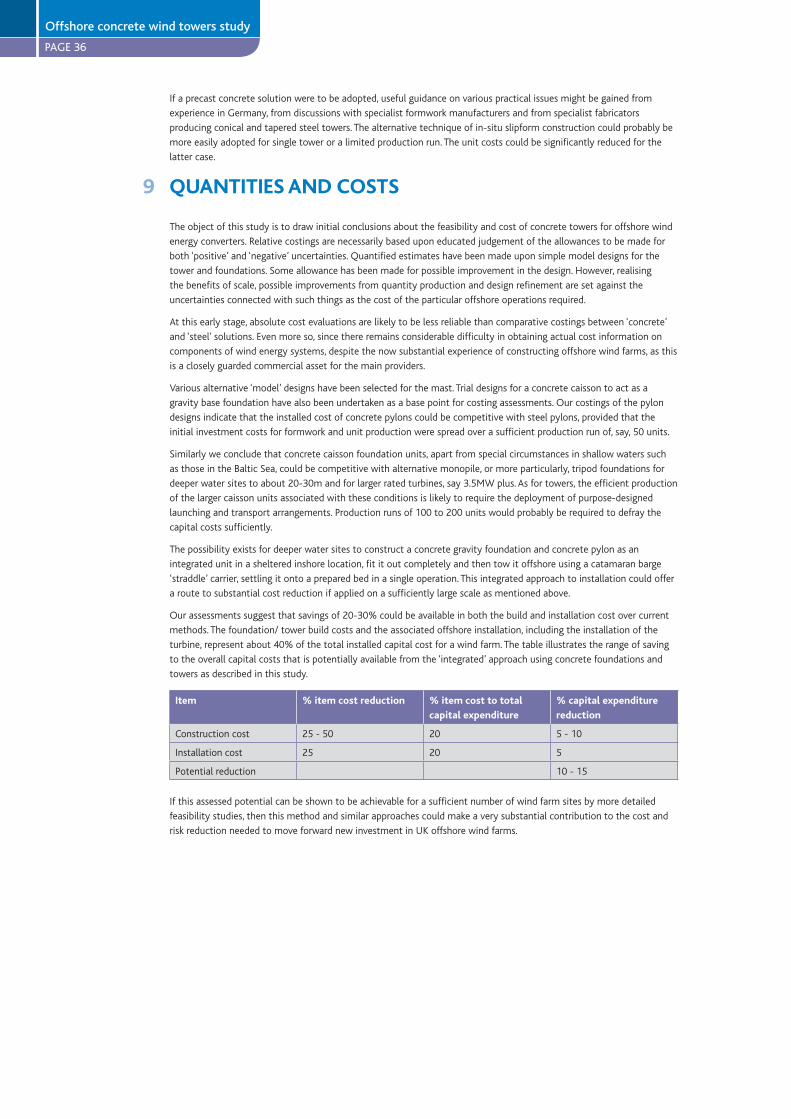
PAGE 36
If a precast concrete solution were to be adopted, useful guidance on various practical issues might be gained from
experience in Germany, from discussions with specialist formwork manufacturers and from specialist fabricators
producing conical and tapered steel towers. The alternative technique of in-situ slipform construction could probably be
more easily adopted for single tower or a limited production run. The unit costs could be significantly reduced for the
latter case.
9 QUANTITIES AND COSTS
The object of this study is to draw initial conclusions about the feasibility and cost of concrete towers for offshore wind
energy converters. Relative costings are necessarily based upon educated judgement of the allowances to be made for
both ‘positive’ and ‘negative’ uncertainties. Quantified estimates have been made upon simple model designs for the
tower and foundations. Some allowance has been made for possible improvement in the design. However, realising
the benefits of scale, possible improvements from quantity production and design refinement are set against the
uncertainties connected with such things as the cost of the particular offshore operations required.
At this early stage, absolute cost evaluations are likely to be less reliable than comparative costings between ‘concrete’
and ‘steel’ solutions. Even more so, since there remains considerable difficulty in obtaining actual cost information on
components of wind energy systems, despite the now substantial experience of constructing offshore wind farms, as this
is a closely guarded commercial asset for the main providers.
Various alternative ‘model’ designs have been selected for the mast. Trial designs for a concrete caisson to act as a
gravity base foundation have also been undertaken as a base point for costing assessments. Our costings of the pylon
designs indicate that the installed cost of concrete pylons could be competitive with steel pylons, provided that the
initial investment costs for formwork and unit production were spread over a sufficient production run of, say, 50 units.
Similarly we conclude that concrete caisson foundation units, apart from special circumstances in shallow waters such
as those in the Baltic Sea, could be competitive with alternative monopile, or more particularly, tripod foundations for
deeper water sites to about 20-30m and for larger rated turbines, say 3.5MW plus. As for towers, the efficient production
of the larger caisson units associated with these conditions is likely to require the deployment of purpose-designed
launching and transport arrangements. Production runs of 100 to 200 units would probably be required to defray the
capital costs sufficiently.
The possibility exists for deeper water sites to construct a concrete gravity foundation and concrete pylon as an
integrated unit in a sheltered inshore location, fit it out completely and then tow it offshore using a catamaran barge
‘straddle’ carrier, settling it onto a prepared bed in a single operation. This integrated approach to installation could offer
a route to substantial cost reduction if applied on a sufficiently large scale as mentioned above.
Our assessments suggest that savings of 20-30% could be available in both the build and installation cost over current
methods. The foundation/ tower build costs and the associated offshore installation, including the installation of the
turbine, represent about 40% of the total installed capital cost for a wind farm. The table illustrates the range of saving
to the overall capital costs that is potentially available from the ‘integrated’ approach using concrete foundations and
towers as described in this study.
Item % item cost reduction % item cost to total
capital expenditure
% capital expenditure
reduction
Construction cost 25 - 50 20 5 - 10
Installation cost 25 20 5
Potential reduction 10 - 15
If this assessed potential can be shown to be achievable for a sufficient number of wind farm sites by more detailed
feasibility studies, then this method and similar approaches could make a very substantial contribution to the cost and
risk reduction needed to move forward new investment in UK offshore wind farms.
Offshore concrete wind towers study
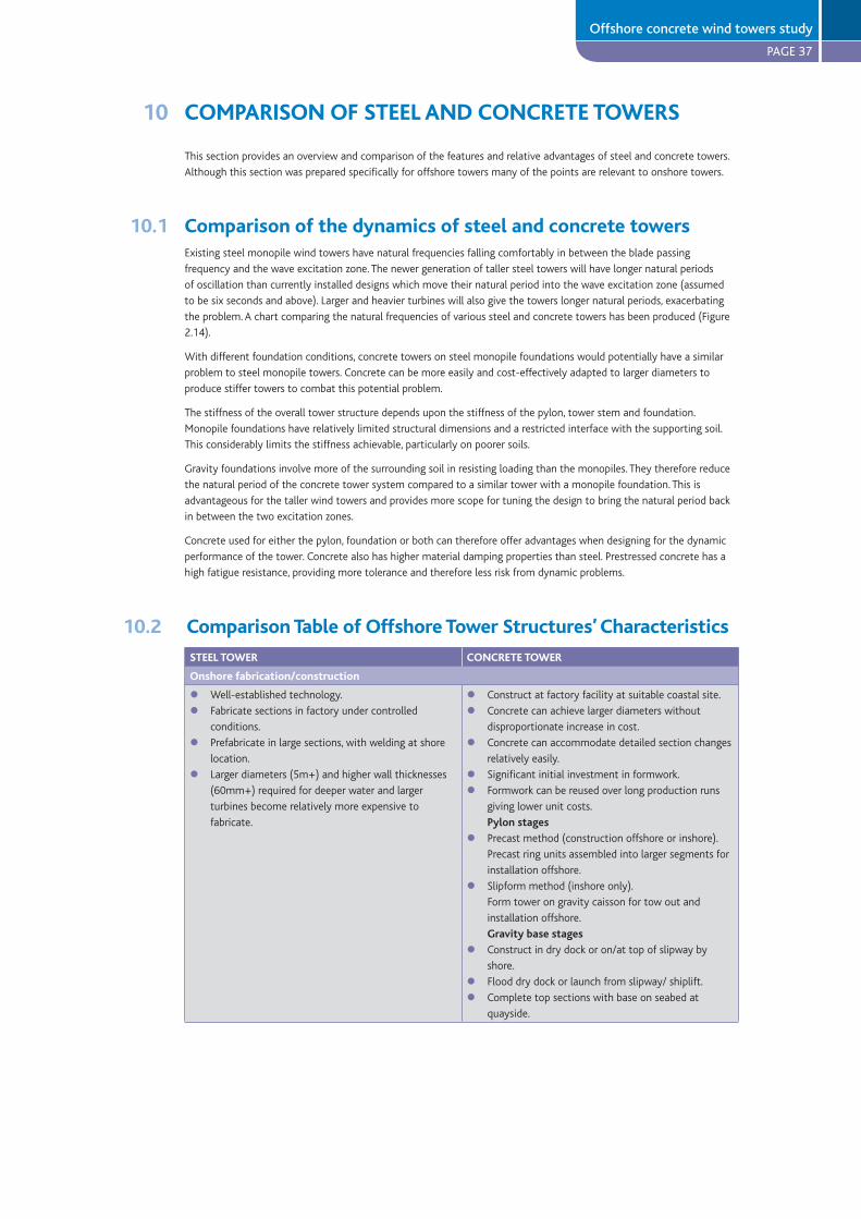
PAGE 37
10 COMPARISON OF STEEL AND CONCRETE TOWERS
This section provides an overview and comparison of the features and relative advantages of steel and concrete towers.
Although this section was prepared specifically for offshore towers many of the points are relevant to onshore towers.
10.1 Comparison of the dynamics of steel and concrete towersExisting steel monopile wind towers have natural frequencies falling comfortably in between the blade passing
frequency and the wave excitation zone. The newer generation of taller steel towers will have longer natural periods
of oscillation than currently installed designs which move their natural period into the wave excitation zone (assumed
to be six seconds and above). Larger and heavier turbines will also give the towers longer natural periods, exacerbating
the problem. A chart comparing the natural frequencies of various steel and concrete towers has been produced (Figure
2.14).
With different foundation conditions, concrete towers on steel monopile foundations would potentially have a similar
problem to steel monopile towers. Concrete can be more easily and cost-effectively adapted to larger diameters to
produce stiffer towers to combat this potential problem.
The stiffness of the overall tower structure depends upon the stiffness of the pylon, tower stem and foundation.
Monopile foundations have relatively limited structural dimensions and a restricted interface with the supporting soil.
This considerably limits the stiffness achievable, particularly on poorer soils.
Gravity foundations involve more of the surrounding soil in resisting loading than the monopiles. They therefore reduce
the natural period of the concrete tower system compared to a similar tower with a monopile foundation. This is
advantageous for the taller wind towers and provides more scope for tuning the design to bring the natural period back
in between the two excitation zones.
Concrete used for either the pylon, foundation or both can therefore offer advantages when designing for the dynamic
performance of the tower. Concrete also has higher material damping properties than steel. Prestressed concrete has a
high fatigue resistance, providing more tolerance and therefore less risk from dynamic problems.
10.2 Comparison Table of Offshore Tower Structures’ Characteristics
STEEL TOWER CONCRETE TOWER
Onshore fabrication/construction
Well-established technology.
Fabricate sections in factory under controlled
conditions.
Prefabricate in large sections, with welding at shore
location.
Larger diameters (5m+) and higher wall thicknesses
(60mm+) required for deeper water and larger
turbines become relatively more expensive to
fabricate.
ll
l
l
Construct at factory facility at suitable coastal site.
Concrete can achieve larger diameters without
disproportionate increase in cost.
Concrete can accommodate detailed section changes
relatively easily.
Significant initial investment in formwork.
Formwork can be reused over long production runs
giving lower unit costs.
Pylon stages
Precast method (construction offshore or inshore).
Precast ring units assembled into larger segments for
installation offshore.
Slipform method (inshore only).
Form tower on gravity caisson for tow out and
installation offshore.
Gravity base stages
Construct in dry dock or on/at top of slipway by
shore.
Flood dry dock or launch from slipway/ shiplift.
Complete top sections with base on seabed at
quayside.
ll
l
ll
l
l
l
ll
Offshore concrete wind towers study
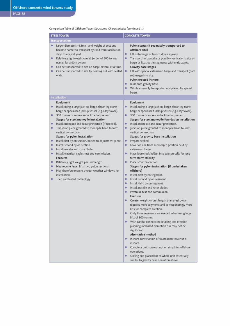
PAGE 38
STEEL TOWER CONCRETE TOWER
Transportation
Larger diameters (4.3m+) and weight of sections
become harder to transport by road from fabrication
shop to coastal yard.
Relatively lightweight overall (order of 500 tonnes
overall for a 90m pylon).
Can be transported to site on barge, several at a time.
Can be transported to site by floating out with sealed
ends.
l
l
ll
Pylon stages (if separately transported to
offshore site)
Lift onto barge or launch down slipway.
Transport horizontally or possibly vertically to site on
barge or float out in segments with ends sealed.
Gravity base stages
Lift with special catamaran barge and transport (part
submerged) to site.
Pylon erected inshore
Built onto gravity base.
Whole assembly transported and placed by special
barge.
ll
l
ll
Installation
Equipment
Install using a large jack-up barge, shear-leg crane
barge or specialised jackup vessel (e.g. Mayflower).
300 tonnes or more can be lifted at present.
Stages for steel monopile installation
Install monopile and scour protection (if needed).
Transition piece grouted to monopile head to form
vertical connection.
Stages for pylon installation
Install first pylon section, bolted to adjustment piece.
Install second pylon section.
Install nacelle and rotor blades.
Install electrical cables test and commission.
Features
Relatively light weight per unit length.
May require fewer lifts (two pylon sections).
May therefore require shorter weather windows for
installation.
Tried and tested technology.
l
l
ll
llll
lll
l
Equipment
Install using a large jack-up barge, shear-leg crane
barge or specialised jackup vessel (e.g. Mayflower).
300 tonnes or more can be lifted at present.
Stages for steel monopile foundation installation
Install monopile and scour protection.
Junction piece grouted to monopile head to form
vertical connection.
Stages for gravity base installation
Prepare seabed
Lower or sink from submerged position held by
catamaran barge.
Place loose rock ballast into caisson cells for long
term storm stability.
Place scour protection.
Stages for pylon installation (if undertaken
offshore)
Install first pylon segment.
Install second pylon segment.
Install third pylon segment.
Install nacelle and rotor blades.
Prestress, test and commission.
Features
Greater weight or unit length than steel pylon
requires more segments and correspondingly more
lifts for complete erection.
Only three segments are needed when using large
lifts of 300 tonnes.
With careful connection detailing and erection
planning increased disruption risk may not be
significant.
Alternative method
Inshore construction of foundation tower unit
inshore.
Complete unit tow-out option simplifies offshore
operations.
Sinking and placement of whole unit essentially
similar to gravity base operation above.
l
l
ll
ll
l
l
lllll
l
l
l
l
l
l
Comparison Table of Offshore Tower Structures’ Characteristics (continued ...)
Offshore concrete wind towers study

PAGE 39
STEEL TOWER CONCRETE TOWER
Performance
Static loading: plenty of reserve capacity in section.
Dynamic loading and response: the natural periods
of present designs (circa six seconds) lie between
the blade passing period (one to two seconds) and
the periods of extreme wave conditions (six seconds
plus).
Taller turbines need larger pylon and foundation
diameters, providing sufficient stiffness to control
the dynamic response (i.e. to keep the natural base
period of the pylon-foundation system below the
periods of extreme wave conditions).
Larger diameters will require larger wall thickness,
making steel harder to procure and fabricate than
hitherto, as well as heavier.
Larger diameter elements will be more difficult to
install.
Connections (flanges etc.) – lives are limited by
fatigue.
ll
l
l
l
l
If supported on a monopile foundation, require large
diameter for concrete solution to avoid wave period
resonance.
A spread foundation (gravity or piled) in contrast has
potential to give good dynamic response for a large
height tower.
Low maintenance.
Prestress can improve durability and provide a good
fatigue performance.
Concrete has higher material damping than steel:
potentially more tolerant of occasional resonance
and avoidance of ‘ringing’ due to impact by breaking
waves.
Significant potential for further value engineering:
use of higher strength concrete; use of fibres to
reduce vertical rebar and improve durability; use of
carbon fibre reinforced polymer (CFRP) prestressed
concrete.
l
l
ll
l
l
Maintenance
Corrosion protection: high specification paint
systems have about 15 to 20 years to first
maintenance. Repainting may therefore be necessary
if a design life of more than 20 years is required,
particularly in the intertidal and splash zones.
Cathodic protection below mean sea level will also
require periodic maintenance.
Maintenance is difficult in isolated offshore
structures.
Bolted flanges particularly at lower levels are
vulnerable to corrosion.
l
l
l
Highly durable if good quality construction.
Very little maintenance for structure.
ll
Upgrade
Offshore wind energy converters have a typical
design life of about 20 years. It may be possible to
extend their life if required, but control of corrosion
and of fatigue damage at connections could present
significant problems. If the foundations and pylon are
still serviceable, then the turbine could be replaced
with a newer model.
l Concrete can be very durable (design life 50 to 100
years), thus the reuse of tower by upgrading the
turbine at 20 years is highly possible. At this stage,
the foundation and pylon, which may originally
comprise some 40% of the overall cost of a new
development, is almost “free”.
A prestressed concrete section could be strengthened
relatively easily for potentially higher loads, from
newer larger turbines by providing some margin in
strength of concrete selected, and by subsequently
increasing the vertical prestress force by installing
‘external’ unbonded tendons coupled to the inner
face of the pylon walls.
l
l
Decommissioning
Large diameter monopiles cannot be extracted at
present; therefore they will have to be cut off at or
below seabed level.
Steel of tower can be brought onshore and recycled.
l
l
Offshore assembled towers
Pylon unbolted in sections and returned to shore for
disposal or recycling.
Gravity foundation could be deballasted and floated
back to shore for decommissioning.
Large diameter monopiles if used cannot be
extracted at present; therefore they will have to be
cut off at or below seabed level.
Inshore constructed tower/ foundation units
The whole installation can be reversed in effect,
utilising equipment similar to that for original
installation.
l
l
l
l
Comparison Table of Offshore Tower Structures’ Characteristics (continued ...)
Offshore concrete wind towers study
PAGE 40
11 OFFSHORE STUDY CONCLUSIONS
The main conclusions are:
Offshore wind farms are generally becoming larger, with a move to more units in deeper water, and deploying larger
turbines. This trend points to the need for taller and stronger towers.
An outline design of a prestressed concrete tower has been prepared for use offshore with the larger turbines likely
to be used in the Round 2 offshore programme. The design is considered to be feasible and economic, although it will
require further development to achieve optimal competitiveness.
Concrete solutions offer advantages and disadvantages for the various scenarios for current offshore wind energy
converters. The balance of advantage for taller offshore wind energy converter towers is shifting towards concrete
design solutions.
Concrete gravity foundations are competitive with steel alternatives (tripod system) in deeper water (particularly in the
range of 15-30 metres), although the actual advantage would depend on the specific site conditions.
An integrated design of concrete caisson and tower could be assembled in sheltered inshore waters, towed out as
a completed unit and sunk at its offshore location. This approach could reduce substantially the number of critical
offshore operations and thereby the associated weather risk. It could provide a radical alternative to current offshore
wind farm construction methods and potentially could provide significantly lower out-turn costs than other existing
deeper-water solutions such as the steel tripod foundation.
Concrete design solutions have a potential for longer reliable operational lives (50-100 years) allowing reuse of the
tower and foundation structure for later re-fits of the turbine and mechanical/electrical plant. They could thereby give
significantly improved longer term financial returns and substantial improvements in sustainability.
There is a very large programme of offshore wind farm development planned for UK and European coastal waters over
the next five years. There is likely to be a continuing programme beyond that, with an increasing proportion of sites
to be found in deeper waters further offshore. All this implies the need for a significantly increased industrial capacity
to achieve it. The introduction of concrete designs as an alternative to steel could offer the important benefit of
mobilising a wider sector of the industrial and technological resources of the civil engineering industry. This would tend
to maintain or extend competition and provide more options for accommodating local economic and employment
circumstances.
12 FIGURES - OFFSHORE WIND TOWERS
Figure No.
2.1 GENERAL STUDY SCENARIO
2.2 CONCRETE TOWER - Continuous taper design
2.3 CONCRETE TOWER - Necked stem design
2.4 CONCRETE FOUNDATION - Gravity base solution
2.5 CONCRETE PYLON - With steel monopile substructure
2.6 PRODUCTION PROCESS - Concrete pylon
2.7 TOWER SECTIONS - For offshore erection
2.8 TOWER SECTIONS - Showing build-up from precast concrete ring units
2.9 PRECAST CONCRETE RING UNITS - Outline details
2.10 JOINT BETWEEN TOWER SECTION - Internal prestress arrangement
2.11 COMPOSITE/HYBRID ARRANGEMENTS FOR WIND TOWER STRUCTURE - Flexibility of solution
2.12 INSTALLATION OF CONCRETE TOWER AND GRAVITY FOUNDATION - Methods 1 & 2
(Pylon construction offshore)
2.13 INSTALLATION OF CONCRETE TOWER AND GRAVITY FOUNDATION - Method 3 (Pylon construction inshore)
2.14 DYNAMIC RESPONSES OF VARIOUS TOWER DESIGNS
l
l
l
l
l
l
Offshore concrete wind towers study

PAGE 41
Figure 2.1GENERAL STUDY SCENARIO
Offshore - figures
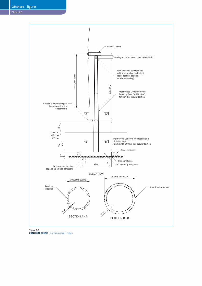
PAGE 42
Figure 2.2CONCRETE TOWER -
Offshore - figures
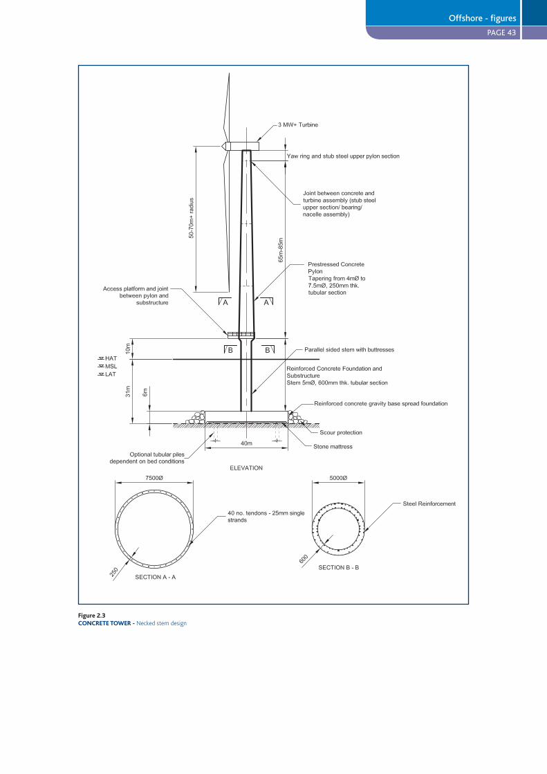
PAGE 43
Figure 2.3CONCRETE TOWER -
Offshore - figures
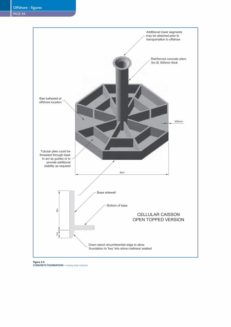
PAGE 44
Figure 2.4CONCRETE FOUNDATION -
Offshore - figures
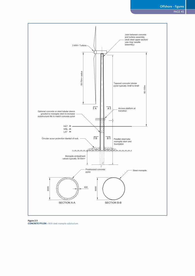
PAGE 45
Figure 2.5CONCRETE PYLON -
Offshore - figures

PAGE 46
Figure 2.6PRODUCTION PROCESS -
Figure 2.7TOWER SECTIONS -
Offshore - figures
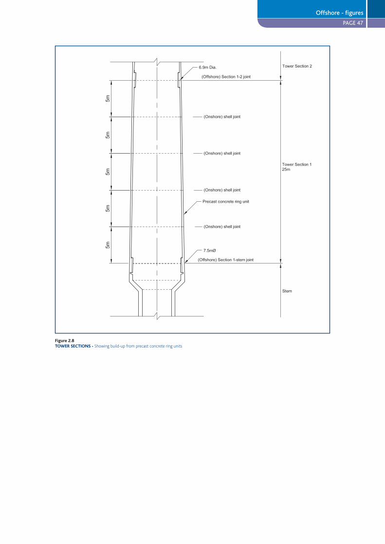
PAGE 47
Figure 2.8TOWER SECTIONS -
Offshore - figures

PAGE 48
For alternative solution using externalunbonded prestressing see onshore study figures
Figure 2.9PRECAST CONCRETE RING UNITS -
Offshore - figures
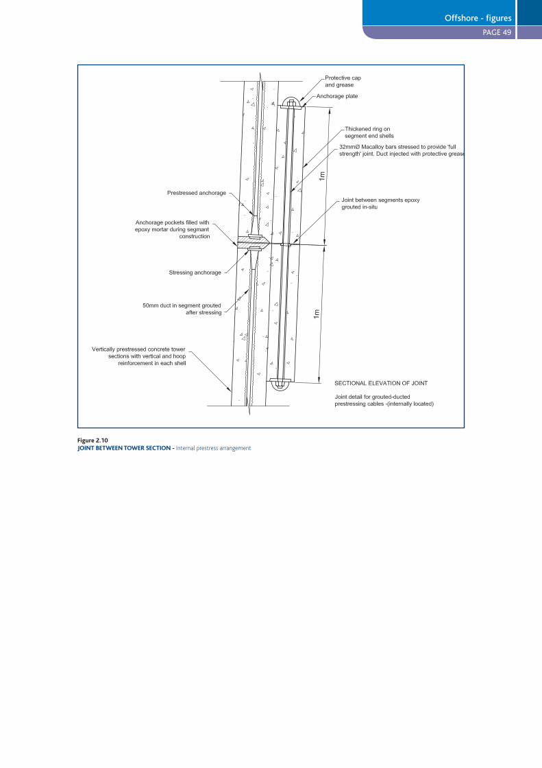
PAGE 49
Figure 2.10JOINT BETWEEN TOWER SECTION -
Offshore - figures
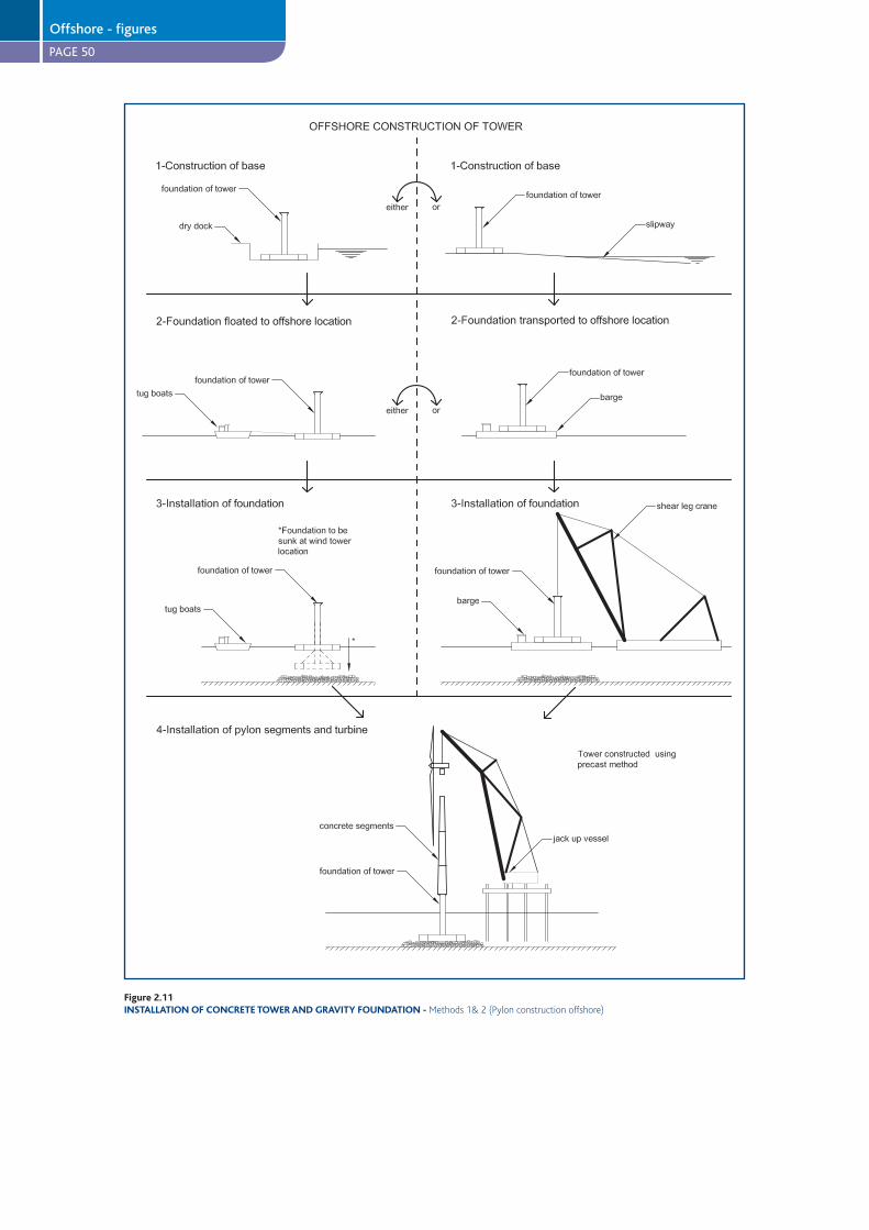
PAGE 50
Figure 2.11INSTALLATION OF CONCRETE TOWER AND GRAVITY FOUNDATION -
Offshore - figures
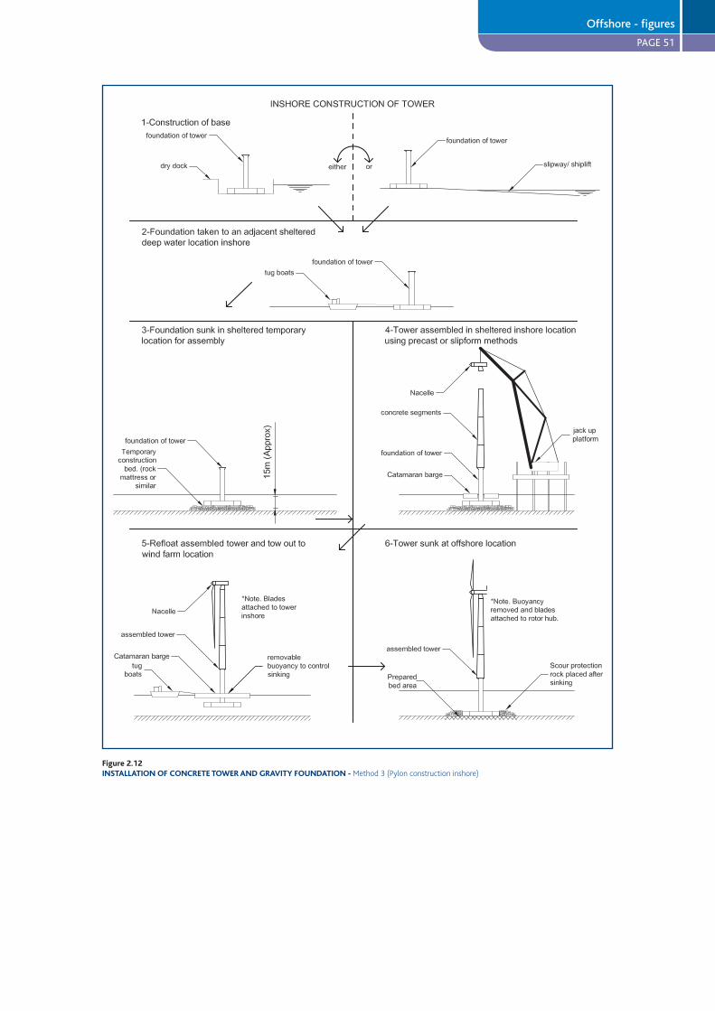
PAGE 51
Figure 2.12INSTALLATION OF CONCRETE TOWER AND GRAVITY FOUNDATION -
Offshore - figures
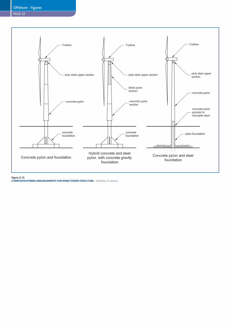
PAGE 52
Figure 2.13COMPOSITE/HYBRID ARRANGEMENTS FOR WIND TOWER STRUCTURE -
Offshore - figures
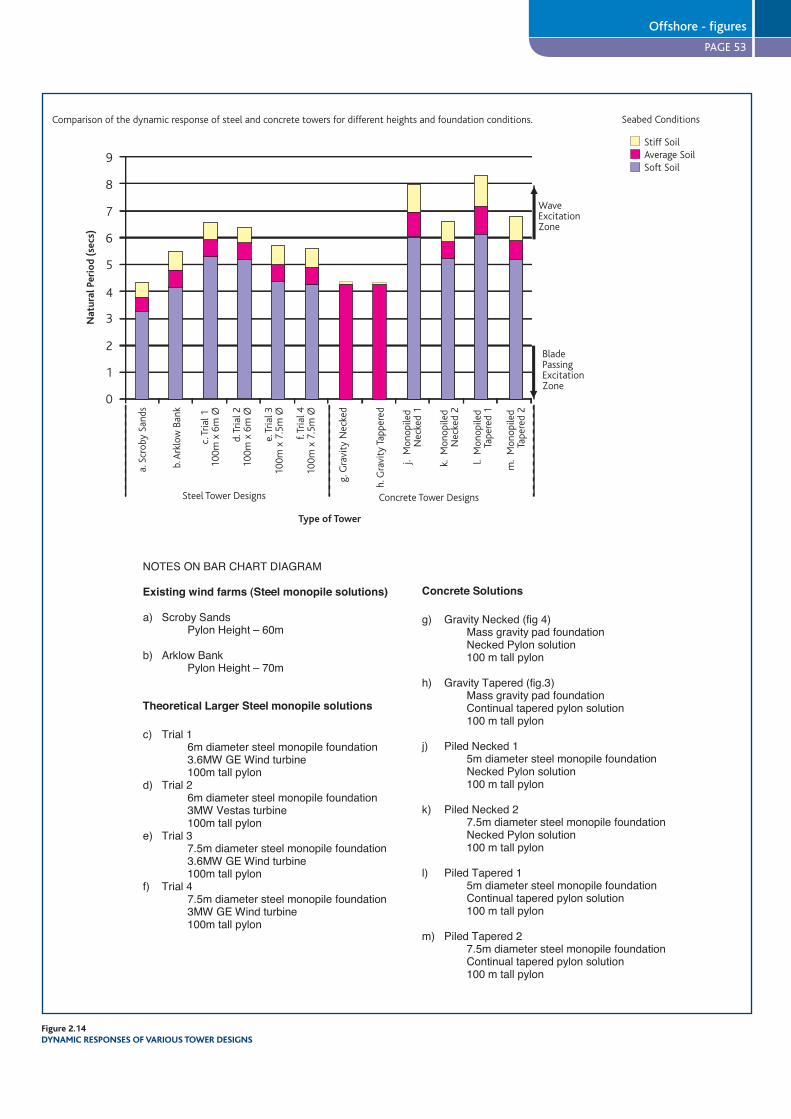
PAGE 53
Comparison of the dynamic response of steel and concrete towers for different heights and foundation conditions.
9
8
7
6
5
4
3
2
1
0
Nat
ural
Per
iod
(sec
s)
a. S
crob
y Sa
nds
b. A
rklo
w B
ank
c. T
rial 1
10
0m x
6m
Ø
d. T
rial 2
100m
x 6
m Ø
e. T
rial 3
100m
x 7
.5m
Ø
f. Tr
ial 4
100m
x 7
.5m
Ø
g. G
ravi
ty N
ecke
d
h. G
ravi
ty T
appe
red
j. M
onop
iled
Nec
ked
1
k. M
onop
iled
Nec
ked
2
l. M
onop
iled
Tape
red
1
m.
Mon
opile
d Ta
pere
d 2
Steel Tower Designs Concrete Tower Designs
Type of Tower
WaveExcitationZone
BladePassingExcitationZone
Stiff SoilAverage SoilSoft Soil
Seabed Conditions
Figure 2.14DYNAMIC RESPONSES OF VARIOUS TOWER DESIGNS
NOTES ON BAR CHART DIAGRAM
Existing wind farms (Steel monopile solutions)
a) Scroby SandsPylon Height – 60m
b) Arklow BankPylon Height – 70m
Theoretical Larger Steel monopile solutions
c) Trial 16m diameter steel monopile foundation3.6MW GE Wind turbine100m tall pylon
d) Trial 26m diameter steel monopile foundation3MW Vestas turbine100m tall pylon
e) Trial 37.5m diameter steel monopile foundation3.6MW GE Wind turbine100m tall pylon
f) Trial 47.5m diameter steel monopile foundation3MW GE Wind turbine100m tall pylon
Concrete Solutions
g) Gravity Necked (fig 4)Mass gravity pad foundationNecked Pylon solution100 m tall pylon
h) Gravity Tapered (fig.3)Mass gravity pad foundationContinual tapered pylon solution100 m tall pylon
j) Piled Necked 15m diameter steel monopile foundationNecked Pylon solution100 m tall pylon
k) Piled Necked 27.5m diameter steel monopile foundationNecked Pylon solution100 m tall pylon
l) Piled Tapered 1
Concrete Solutions
g) Gravity Necked (fig 4)Mass gravity pad foundationNecked Pylon solution100 m tall pylon
h) Gravity Tapered (fig.3)Mass gravity pad foundationContinual tapered pylon solution100 m tall pylon
j) Piled Necked 15m diameter steel monopile foundationNecked Pylon solution100 m tall pylon
k) Piled Necked 27.5m diameter steel monopile foundationNecked Pylon solution100 m tall pylon
l) Piled Tapered 15m diameter steel monopile foundationContinual tapered pylon solution100 m tall pylon
m) Piled Tapered 27.5m diameter steel monopile foundationContinual tapered pylon solution100 m tall pylon
Offshore - figures
PAGE 54
13 GENERAL CONCLUSIONS
Although some large concrete wind towers have been constructed in Germany and elsewhere in Europe, they represent
a small fraction of the present tower population. This report points to the potential for improved competitiveness of
prestressed concrete towers, particularly for taller towers and larger rated turbines for both offshore and onshore
wind farms.
For onshore wind farms viable designs for both precast and in-situ slipform construction methods are possible.
For offshore wind farms, precast concrete tower designs following current offshore erection methods are considered
to be feasible, and possibly competitive. The lower unit construction costs will tend to be offset by possibly slightly
longer erection cycles, and the balance of competitiveness could be affected by plant availability and other market
circumstances.
Concrete gravity foundations could provide significant benefits and cost savings given appropriate site circumstances,
particularly for water depths in the range 15-30 metres.
An innovative approach to construction of an integrated tower/ foundation structure at an inshore site is proposed,
followed by transportation and placement offshore of the fully outfitted unit by a purpose designed lift barge. This
combines the most economic construction solutions and circumstances with minimum offshore work and risk. This
scheme has the potential to reduce the installed cost of the tower structure by as much as 25%.
Further conclusions are:
Concrete tower solutions are adaptable and durable.
The high fatigue resistance of prestressed concrete, combined with the good material damping properties of the
concrete, can provide a solution which will be potentially less susceptible to and more tolerant of occasional
resonance, and therefore have a reduced risk of dynamic problems.
Given careful design of key details, the high potential durability of concrete can be realised. The tower will need
little maintenance during a long design life.
The use of prestressed concrete can further increase the tower’s durability.
Prestressed concrete towers can be adapted relatively easily to cope with some future increase in loading associated
with re-using the tower.
For taller towers with high top head loading, concrete pylons can be cost-effectively stiffened by enlarging the
diameter of the lower tower section above the wave affected zone. This will reduce susceptibility to resonant
exposure to excitation by energetic waves.
Concrete gravity foundations have the potential to give taller towers an improved dynamic response over monopile
foundations.
Concrete solutions are heavier than equivalent steel solutions. Careful selection of section size, concrete strength
and the use of prestress can reduce the difference.
A substantial initial investment in formwork and other equipment will be needed for low unit cost of tower pylons
and rapid production. A large enough base market will be needed to fully realise competitive advantages. These
investment costs will be larger for offshore designs than for onshore designs.
The potentially longer service life of concrete towers can be used to significant long term advantage by the
adoption of a turbine re-fit programme, involving the replacement of the turbine after the expiry of its (20 year) life.
This approach could have a profound impact on the sustainability of the wind energy programme as a whole.
l
l
l
l
l
l
l
l
l
l
General conclusions
PAGE 55
14 REFERENCES
1. BWEA Report, Offshore Wind at the Crossroads, British Wind Energy Association Offshore Wind Conference
April 2006
2. Boyle, G, UK Offshore Wind Potential, reFOCUS magazine, Elsevier, July/August 2006
3. Per Vølund, Concrete is the future of offshore foundations, International Conference and Exhibition - Copenhagen
Offshore Wind 2005, ENERGI E2, 2005
4. Enercon GmbH, Tower Versions, 2004. Available from: www1.enercon.de
5. Seidel, M, Experiences with two of the world’s largest wind turbine towers. Proceedings of the 2003 European Wind
Energy Conference and Exhibition, 16-19 June 2003 Madrid, GE Wind Energy GmbH, 2003
6. Brughuis, FJ, Advanced tower solutions for large wind turbines and extreme tower heights. Proceedings of the 2003
European Wind Energy Conference and Exhibition, 16-19 June 2003 Madrid, Mecal Applied Mechanics BV, 2003
7. Brughuis, FJ, 2004. Improved return on investment due to larger wind turbines. Proceedings of the 2004 European
Wind Energy Conference and Exhibition, 22-25 November 2004 London. Netherlands: Mecal Applied Mechanics BV
8. See Nordex website: www.nordex-online.com
9. See BWEA website: www.bwea.com
Background readingBWEA Press Release, Global wind industry grows as positive assessment of grid integration reported from Germany,
2005. Available from: www.bwea.com/media/2005.html
BWEA Report, Onshore Wind: Powering Ahead, March 2006
The Concrete Centre, An estimate of the embodied CO2 in steel and concrete wind turbine towers, 2005.
Gifford, Review of the estimated embodied CO2 in steel and concrete wind towers. (Report No. 12318/R02), 2005
Wind Power in the UK, Sustainable Development Commission, 2005. Available from: www.sd-commission.org.uk
APPENDIX A – Embodied CO2 estimates for wind towers
Table A1 provides comparisons of the typical quantities of CO2 embodied in structural steel and reinforced concrete.
Calculated by independent industry experts, the values reported encompass average CO2 levels associated with material
extraction, production and transportation.
Based on these figures, the estimated total mass of embodied CO2 in a 70m wind tower constructed from steel and
concrete is compared in Table A2. 70m was chosen as a height representative of typical onshore solutions and owing to
the widespread availability of industry data on steel towers of this height.
Recognising the indicative nature of these calculations, it is clear that embodied levels of CO2 in concrete wind towers
can be significantly lower than for steel (64% reduction in Table A2).
Concrete offers this improvement as, despite cement production’s energy-intensive nature, it is a locally sourced
material produced predominantly from materials with low environmental footprints. For further information on the
cement and concrete industry’s commitment to sustainability, please refer to www.cementindustry.org.uk and
www.sustainableconcrete.org.uk
References and background reading
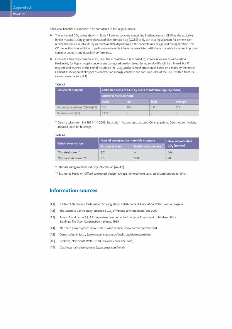
PAGE 56
Appendix A
Additional benefits of concrete to be considered in this regard include:
The embodied CO2 values shown in Table A1 are for concrete containing Portland cement CEMI as the exclusive
binder material. Using ground granulated blast furnace slag (GGBS) or fly ash as a replacement for cement can
reduce the values in Table A1 by as much as 40% depending on the concrete mix design and the application. This
CO2 reduction is in addition to performance benefits inherently associated with these materials including improved
concrete strength and durability performance.
Concrete inherently consumes CO2 from the atmosphere it is exposed to, a process known as carbonation.
Particularly for high strength concrete structures, carbonation levels during service life will be minimal, but if
recycled and crushed at the end of its service life, CO2 uptake is much more rapid. Based on a study by the British
Cement Association of all types of concrete, on average concrete can consume 20% of the CO2 emitted from its
cement manufacture [A1].
Table A1
Structural material Embodied mass of CO2 by mass of material (kgCO2/tonne)
Reinforcement content
none low high average
* Density taken from EN 1991-1-1:2002, Eurocode 1. Actions on structures. General actions. Densities, self-weight,
imposed loads for buildings.
Table A2
Wind tower optionMass of construction materials (tonnes) Mass of embodied
CO2 (tonnes)Structural steel Reinforced concrete
70m steel tower * 125 ~ 242
70m concrete tower ** 2.0 550 88
* Estimate using available industry information [A4-A7]
** Estimated based on Gifford conceptual design (average reinforcement level, steel contribution at joints)
Information sources
[A1] C Clear, T De Saulles, Carbonation Scoping Study, British Cement Association, 2007, draft in progress
[A2] The Concrete Centre study, Embodied CO2 of various concrete mixes, due 2007
[A3] Amato A and Eaton K J., A Comparative Environmental Life Cycle Assessment of Modern Office
Buildings, The Steel Construction Institute, 1998
[A4] Northern power Systems NW 100/19 wind turbine (www.northernpower.com)
[A5] Danish Wind Industry (www.newenergy.org.cn/english/guide/towerm.htm)
[A6] Crokwell, New South Wales 1998 (www.bluecopesteel.com)
[A7] Clashindarroch development (www.amec.com/wind)
l
l
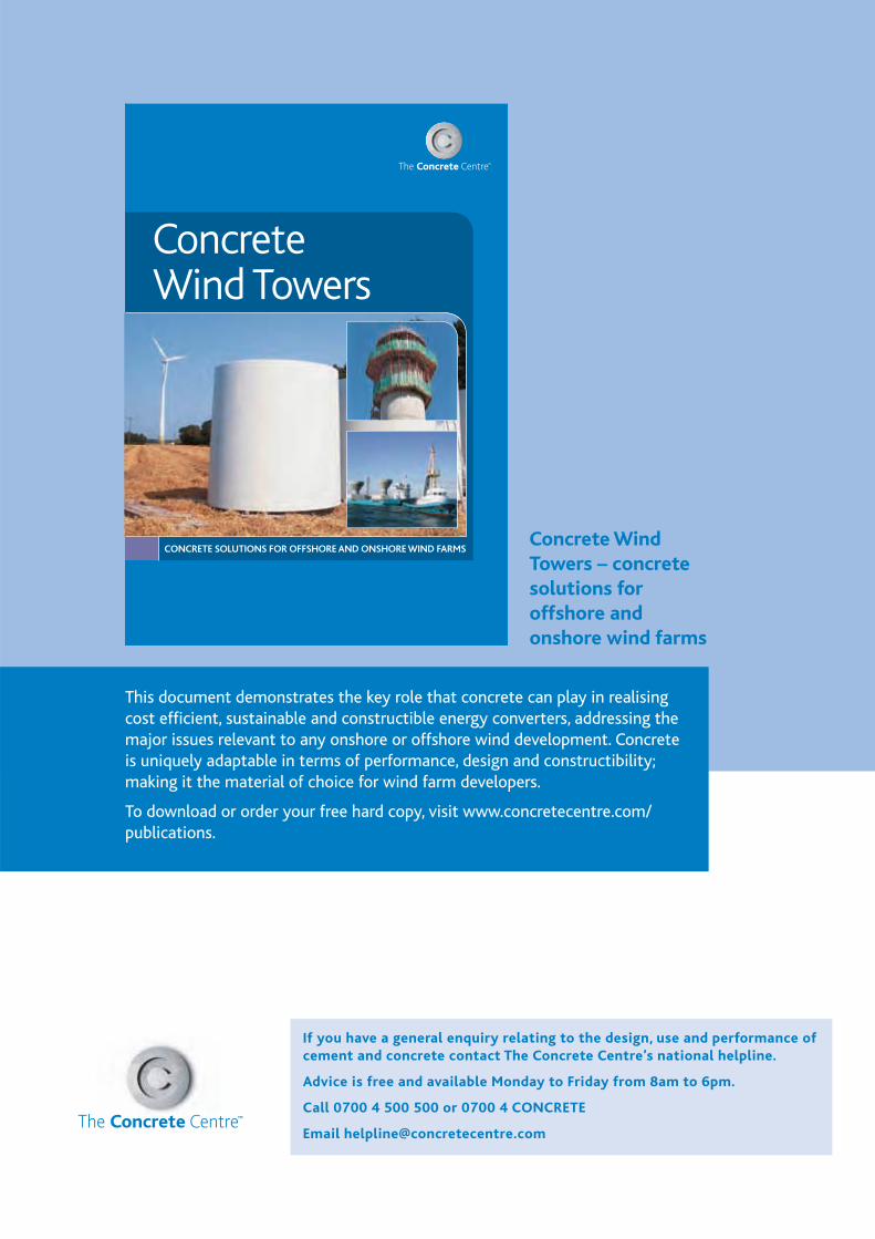
PAGE 57
If you have a general enquiry relating to the design, use and performance of cement and concrete contact The Concrete Centre’s national helpline.
Advice is free and available Monday to Friday from 8am to 6pm.
Call 0700 4 500 500 or 0700 4 CONCRETE
Email [email protected]
CONCRETE SOLUTIONS FOR OFFSHORE AND ONSHORE WIND FARMS
Concrete Wind Towers
Concrete Wind Towers – concrete solutions for offshore and onshore wind farms
This document demonstrates the key role that concrete can play in realising cost efficient, sustainable and constructible energy converters, addressing the major issues relevant to any onshore or offshore wind development. Concrete is uniquely adaptable in terms of performance, design and constructibility; making it the material of choice for wind farm developers.
To download or order your free hard copy, visit www.concretecentre.com/publications.
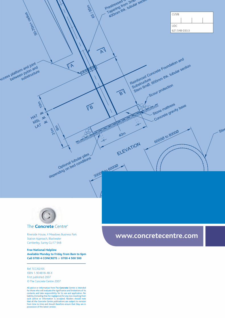
All advice or information from The Concrete Centre is intended for those who will evaluate the significance and limitations of its contents and take responsibility for its use and application. No liability (including that for negligence) for any loss resulting from such advice or information is accepted. Readers should note that all the Concrete Centre publications are subject to revision from time to time and should therefore ensure that they are in possession of the latest version.
Free National Helpline
Available Monday to Friday from 8am to 6pm
Call 0700 4 CONCRETE 0700 4 500 500
www.concretecentre.com