Embed Size (px)
Citation preview

< 1 >
CONCRETE SUSTAINABILITY REPORT NATIONAL READY MIXED CONCRETE ASSOCIATION CSR04—OCTOBER 2011
hen it comes to commercial building construction, concrete offers several environmental benefits. For example, the production of concrete is resource effi-cient and the ingredients require little processing.
Most materials for concrete are acquired and manufactured locally which minimizes transportation energy and associated greenhouse gas emissions. Concrete incorporates recycled industrial byproducts such as fly ash, slag and silica fume which helps reduce embodied energy, carbon footprint and waste. Concrete has a long service life, thereby increasing the period between reconstruc-tion, repair and main-tenance and associ-ated environmental impacts. Because concrete is light in color it can help minimize the urban heat island effect when used as pave-ment for parking ar-eas and plazas or for exterior cladding.
Most importantly, because of concrete’s thermal mass, concrete buildings can be extremely energy efficient. From a life cycle perspective, con-crete-frame buildings perform well when compared to steel-frame buildings. As a result, concrete buildings have lower car-bon footprint over their entire life cycle. This paper explores how concrete performs for commercial buildings using life cycle assessment (LCA) methods of determining environmental per-formance.
What is Life Cycle Assessment?
Life cycle assessment, or LCA, is the investigation and evaluation of the environmental impacts of a product, process or service. LCA evaluates all stages of a product’s life and considers each stage interdependently, meaning that one operation leads to the next. There are several life cycle stages for a given system or process. These stages can include, but are not limited to, those shown in Figure 1. Inputs may include raw materials and energy.
Life cycle stages may include raw material acquisition, manufac-turing, building use or operations and, finally, recycling or waste management. The outputs, many of which impact the envi-ronment negatively, include atmospheric emissions, waterborne wastes, solid wastes, coproducts and other releases.
When looking at the environmental impact
of a building, it is important to assess every stage of the environ-mental life cycle, from material extraction, manufacturing and construction; building operations; and the end-of-life stage where the building is demolished and reused or discarded. LCA is the most comprehensive approach to determining the envi-ronmental life cycle impacts of a building and can be used as a tool to make design decisions that would result in lower envi-ronmental impacts.
Life Cycle Assessment of Concrete Buildings By Lionel Lemay, P.E., S.E., LEED AP, Sr. VP, Sustainable Development, NRMCA
W
Figure 1. Life cycle stages, inputs and outputs for life cycle assessment (adapted from EPA).
CONCRETE SUSTAINABILITY REPORT NRMCA CSR04
< 2 >
Per the ISO 140401 and 140442 standards, LCA is conducted in four distinct phases:
1. Goal Definition and Scoping - Define and describe the prod-uct, process or activity being analyzed.
2. Inventory Analysis - Identify and quantify energy, water and materials use and environmental releases. Environmental releases may be solid waste, air emissions and waste wa-ter discharges.
3. Impact Assessment - Assess the potential human and eco-logical effects of energy, water and material usage, and the environmental releases identified in the inventory analysis.
4. Interpretation - Evaluate the results and select the pre-ferred product or process.
The first phase, Goal Definition and Scoping, is relatively simple since one can generally identify and define the product or proc-ess being analyzed. The second phase, Inventory Analysis, is more diffi-cult since one must have the capabilities to measure and account for all inputs and out-puts from a particular product or process. In many cases, it is rela-tively easy to measure the inputs to a product or process but it be-comes much more difficult and expensive to measure environ-mental releases.
The third phase, Impact Assessment, is the most complex phase of an LCA. In this phase, one attempts to equate the environmental releases identified in the Inventory Analysis phase and assess their potential human and ecological effects. The U.S. Environmental Protection Agency (EPA) developed the Tool for the Reduction and Assessment of Chemical and Other Environmental Impacts (TRACI).3 TRACI allows the examination of the potential for impacts associated with the raw material usage and chemical releases resulting from the processes involved in producing a product.
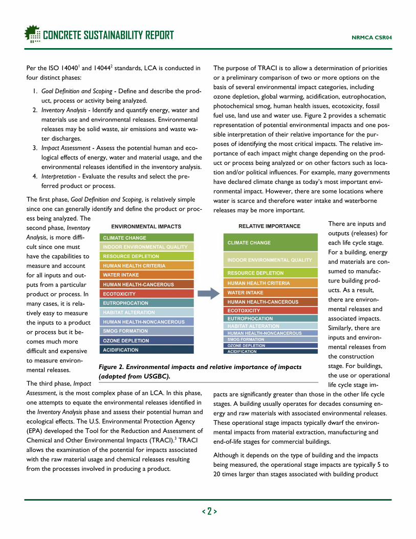
The purpose of TRACI is to allow a determination of priorities or a preliminary comparison of two or more options on the basis of several environmental impact categories, including ozone depletion, global warming, acidification, eutrophocation, photochemical smog, human health issues, ecotoxicity, fossil fuel use, land use and water use. Figure 2 provides a schematic representation of potential environmental impacts and one pos-sible interpretation of their relative importance for the pur-poses of identifying the most critical impacts. The relative im-portance of each impact might change depending on the prod-uct or process being analyzed or on other factors such as loca-tion and/or political influences. For example, many governments have declared climate change as today’s most important envi-ronmental impact. However, there are some locations where water is scarce and therefore water intake and waterborne releases may be more important.
There are inputs and outputs (releases) for each life cycle stage. For a building, energy and materials are con-sumed to manufac-ture building prod-ucts. As a result, there are environ-mental releases and associated impacts. Similarly, there are inputs and environ-mental releases from the construction stage. For buildings, the use or operational life cycle stage im-
pacts are significantly greater than those in the other life cycle stages. A building usually operates for decades consuming en-ergy and raw materials with associated environmental releases. These operational stage impacts typically dwarf the environ-mental impacts from material extraction, manufacturing and end-of-life stages for commercial buildings.
Although it depends on the type of building and the impacts being measured, the operational stage impacts are typically 5 to 20 times larger than stages associated with building product
Figure 2. Environmental impacts and relative importance of impacts (adapted from USGBC).

CONCRETE SUSTAINABILITY REPORT NRMCA CSR04
< 3 >
manufacturing and demolition. In fact, operating buildings in the U.S. consumes 19% of the nation’s energy and 37% of the na-tion’s electricity. In total, commercial buildings account for 19% of the CO2 emissions in the U.S.4 Therefore, when conducting an LCA for buildings, it is extremely important to include the operational stage.
How Can Concrete Help Reduce Life Cycle Impacts of a Building?
Low Processing Energy Water, sand, stone, gravel and other ingredients make up about 90% of a concrete mixture by weight. The process of mining sand and gravel, crushing stone, combining the materials in a concrete plant and transporting concrete to the construction site requires very little energy and therefore only emits a rela-tively small amount of CO2 into the atmosphere. The amount of CO2 embodied in concrete is primarily a function of the ce-ment content in the mix. Cement is an ingredient of concrete. It's the fine, gray powder that, when mixed with water, sand and gravel, forms the rock-like mass known as concrete.
Concrete uses between about 7% and 15% cement by mass depending on the performance requirements of the concrete. The average quantity of portland cement is around 250 kg/m3
(420 lb/yd3). This average quantity has consistently decreased with better optimization of concrete mixtures and increased use of supplementary cementitious materials (SCMs) that can improve the strength and durability characteristics of concrete. As a result, approximately 100 to 300 kg of CO2 is embodied in every cubic meter of concrete (170 to 500 lb per yd3) pro-duced or approximately 5% to 13% of the weight of concrete produced, depending on the mixture proportions, which is rela-tively low when compared to other building materials.5
Concrete also provides the distinct benefit of being a locally produced material. The use of locally manufactured materials reduces the environmental impact of transportation. In addi-tion, using concrete that is produced and manufactured in the same community as the construction site supports the local economy.
Recycled Materials The U.S. concrete industry uses a significant amount of indus-trial byproducts such as fly ash, blast furnace slag and silica fume to supplement a portion of the cement used in concrete. These industrial byproducts, which would otherwise end up in land-
fills, are called supplementary cementitious materials or SCMs for short. The use of SCMs in concrete work in combination with portland cement to improve strength and durability, in addition to reducing the CO2 embodied in concrete by as much as 70%, with typical values ranging between 15 and 40%.
Fly ash is the waste byproduct of burning coal in electrical power plants. Generally, 15 to 20% of burned coal takes the form of fly ash. At one time, most fly ash was landfilled, but today a significant portion is used in concrete. Blast furnace slag is the waste byproduct of iron manufacture. After quenching and grinding, the blast furnace slag takes on much higher value as a supplementary cementitious material for concrete. Blast furnace slag is used as a partial replacement for cement to im-part added strength and durability to concrete. Silica fume is a waste byproduct of processing quartz into silicon or ferrosili-con metals in an electric arc furnace. It consists of superfine, spherical particles that when combined with cement signifi-cantly increases strength and durability of concrete.
The concrete industry also incorporates a variety of environ-mental best management practices in the production of its product. These include the reuse and recycling of waste from concrete manufacture such as water and unused returned con-crete. It also incorporates waste byproducts from other indus-tries such as recycled industrial wastewater, foundry sands, glass and other materials that would typically end up in landfills.
In addition to the use of SCMs in the concrete mix, concrete from demolition can be crushed and recycled as aggregate. Re-cycled aggregate is often used as backfill and pavement base and is sometimes used for making new concrete. Reinforcing steel in concrete (which often is made from recycled materials) can be recycled and reused.6
Indoor Air Quality Indoor air quality can directly impact the health of a building’s occupants. Poor indoor air quality can exacerbate asthma or cause irritation to eyes, nose and throat. Incidences of nose dryness often lead to nose bleeds, skin rash, headaches, upper respiratory distress and dizziness. Outdoor air quality has been regulated and has become cleaner; however, indoor air has de-teriorated. The indoor air quality in buildings may be two to five times more polluted than the outside air. Indoor air quality can be impacted by cigarette or tobacco smoke, high Volatile Or-ganic Compound (VOC) levels due to materials used in lami-
CONCRETE SUSTAINABILITY REPORT NRMCA CSR04
< 4 >
nate, particleboard, hardboard, treated wood, etc., carpeting and cleaning materials, among others building products.
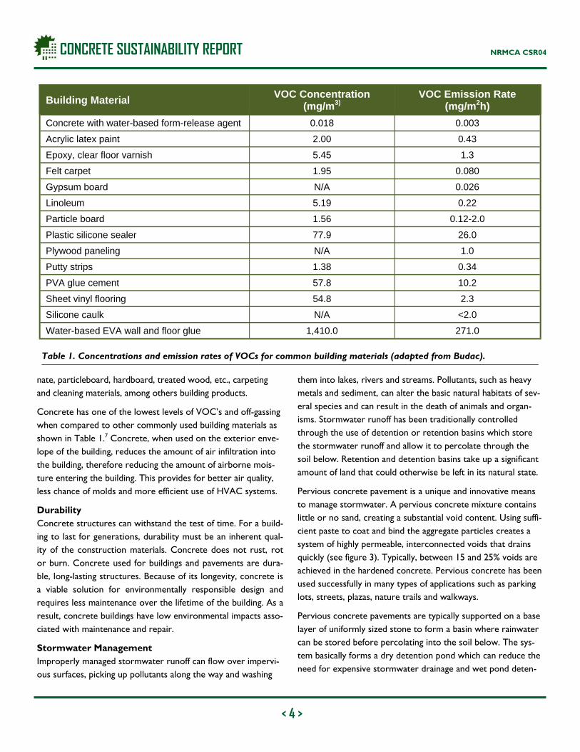
Concrete has one of the lowest levels of VOC’s and off-gassing when compared to other commonly used building materials as shown in Table 1.7 Concrete, when used on the exterior enve-lope of the building, reduces the amount of air infiltration into the building, therefore reducing the amount of airborne mois-ture entering the building. This provides for better air quality, less chance of molds and more efficient use of HVAC systems.
Durability Concrete structures can withstand the test of time. For a build-ing to last for generations, durability must be an inherent qual-ity of the construction materials. Concrete does not rust, rot or burn. Concrete used for buildings and pavements are dura-ble, long-lasting structures. Because of its longevity, concrete is a viable solution for environmentally responsible design and requires less maintenance over the lifetime of the building. As a result, concrete buildings have low environmental impacts asso-ciated with maintenance and repair.
Stormwater Management Improperly managed stormwater runoff can flow over impervi-ous surfaces, picking up pollutants along the way and washing
them into lakes, rivers and streams. Pollutants, such as heavy metals and sediment, can alter the basic natural habitats of sev-eral species and can result in the death of animals and organ-isms. Stormwater runoff has been traditionally controlled through the use of detention or retention basins which store the stormwater runoff and allow it to percolate through the soil below. Retention and detention basins take up a significant amount of land that could otherwise be left in its natural state.
Pervious concrete pavement is a unique and innovative means to manage stormwater. A pervious concrete mixture contains little or no sand, creating a substantial void content. Using suffi-cient paste to coat and bind the aggregate particles creates a system of highly permeable, interconnected voids that drains quickly (see figure 3). Typically, between 15 and 25% voids are achieved in the hardened concrete. Pervious concrete has been used successfully in many types of applications such as parking lots, streets, plazas, nature trails and walkways.
Pervious concrete pavements are typically supported on a base layer of uniformly sized stone to form a basin where rainwater can be stored before percolating into the soil below. The sys-tem basically forms a dry detention pond which can reduce the need for expensive stormwater drainage and wet pond deten-
Building Material VOC Concentration
(mg/m3) VOC Emission Rate
(mg/m2h)
Concrete with water-based form-release agent 0.018 0.003
Acrylic latex paint 2.00 0.43
Epoxy, clear floor varnish 5.45 1.3
Felt carpet 1.95 0.080
Gypsum board N/A 0.026
Linoleum 5.19 0.22
Particle board 1.56 0.12-2.0
Plastic silicone sealer 77.9 26.0
Plywood paneling N/A 1.0
Putty strips 1.38 0.34
PVA glue cement 57.8 10.2
Sheet vinyl flooring 54.8 2.3
Silicone caulk N/A <2.0
Water-based EVA wall and floor glue 1,410.0 271.0
Table 1. Concentrations and emission rates of VOCs for common building materials (adapted from Budac).

CONCRETE SUSTAINABILITY REPORT NRMCA CSR04
< 5 >
tion/retention systems, thereby allowing for more effective land use. In effect, the pervious concrete pavement system serves two functions: 1) as a paved surface for driving, parking or walking, and 2) as a detention basin for storing and treating rainwater during a storm event.
Pervious pavement systems can treat common pollutants found in the urban environment. Pollutants are those typically found on parking areas, including cadmium, oils, lead and gasoline among others. The pollutants are captured in the voids of the pervious concrete and aggregate base layer and the treated water is filtered into the groundwater below. The oil-based pollutants that are stored in the voids of the pervious pavement are digested by naturally occurring microorganisms that inhabit the large surface area surrounding the voids.8
Thermal Mass Thermal mass is the term used to describe a material that ab-sorbs and stores heat energy. In a building system, it is the mass of the building elements that stores heat during the hottest periods of the day and releases the heat during the cooler eve-ning hours. Concrete is one of several building materials that possess thermal mass properties. In the winter season, high thermal mass concrete walls and floors absorbs radiant heat from the sun and gradually releases it back into the occupied
space during the night when the outdoor temperature drops. Concrete is an ideal building material for commercial and resi-dential structures due to its high specific heat, high density and low thermal conductivity.
The distinct benefits of high thermal mass buildings are:
Moderate shifts in peak loads of energy requirements due to the reduction in high fluctuations between indoor and outdoor temperatures.
Heat transfer through a high thermal mass wall is reduced, therefore less energy is used to heat and cool the interior space.
The thermal mass of concrete delays peak temperatures, and reduces and spaces out peak energy loads, therefore shifting the energy demand to off peak periods when util-ity rates may be lower.
The damping and lag effects of a high thermal mass building are shown in Figure 4.
Urban Heat Island Reduction On warm summer days, the air in urban areas can be 3-4 ºC (6-8 °F) hotter than its surrounding areas. This is called the urban heat island effect (see figure 5).9 The use of light colored pave-ments, cladding and roofing in urban areas can contribute to overall energy savings and reduced carbon emissions. Because concrete is light in color, it absorbs less heat and reflects more light than dark-colored materials, therefore maintaining a rela-tively low surface temperature. Concrete has been demon-
Figure 4: Damping and lag effect of thermal mass.
Figure 3. Pervious concrete has between 15 and 25% voids that allow stormwater to percolate through it.

CONCRETE SUSTAINABILITY REPORT NRMCA CSR04
< 6 >
strated to have a positive impact on the localized ambient tem-peratures and therefore reduce energy required to air condi-tion buildings.
A material’s ability to reflect solar radiation is measured by the material’s albedo or measure of solar reflectivity. A material’s albedo is the extent to which the material diffusely reflects light from the sun. Although not always an indicator, materials with a light color have a high albedo whereas materials that appear darker typically have a lower albedo. A material’s ability to re-flect infrared light is directly proportional to a material’s ability to reflect heat from the surface. During the hot summer months, the ambient air surrounding dark colored paving or cladding materials can be up to 10 degrees warmer than paving or cladding with a light color, or high albedo.10
One study measured the temperature of various pavement types during a hot 32 °C (90 °F) summer day and found that weathered concrete had a temperature of 68 °C (155 °F) at the material surface whereas dark asphalt had a temperature of 90 °C (195 °F). The asphalt pavement was 32 °C (40 °F) hotter than the concrete pavement.11
The Urban Heat Island Reduction Program of the U.S. Depart-ment of Energy (DOE) provides several recommendations for reducing urban heat islands. The program suggests that by re-placing dark colored pavements with light and heat-reflective concrete-based materials, along with careful planting of trees, the average summer afternoon temperature in urban areas can
be significantly reduced. Researchers at Lawrence Berkeley National Laboratory (LBNL) have estimated that every 10 per-cent increase in solar reflectance could decrease surface tem-peratures by 4 ºC (7 ºF). Further, they predicted that if pave-ment reflectance throughout a city were increased from 10 percent to 35 percent, the air temperature could potentially be reduced by 0.6 ºC (1 ºF) which would result in significant bene-fits in terms of lower energy use and reduced ozone levels.12 Another separate study estimated over $90 million per year in savings from temperature reductions attributed to increased pavement albedo in the Los Angeles area.13
Depending on the electric power fuel mix, decreased energy demand associated with cool pavements will result in lower associated air pollution and greenhouse gas emissions. Cooler air temperatures also slow the rate of ground-level ozone for-mation and reduce evaporative emissions from vehicles. A 2007 paper estimated that increasing pavement albedo in cities worldwide, from an average of 35 to 39 percent, could achieve reductions in global carbon dioxide (CO2) emissions worth about $400 billion.14
Reduced Lighting Requirements Using concrete for pavements can also help reduce energy de-mand for lighting. A research study analyzed the lighting re-quired to meet specified luminance for an asphalt and a con-crete parking lot. Results indicate that a 250 watt lamp used in a concrete parking lot would produce background luminance equal (or greater) to a 400 watt lamp used in an asphalt parking lot with the same geometric configurations. Therefore, by using a concrete parking surface, energy savings of up to 41% could be realized. With the assumption that an average parking lot lighting system operates up to five hours per day, in one year the asphalt parking lot would consume 60% more energy than the concrete parking lot. In addition, with the increased lumi-nance of a concrete parking lot, the number of light poles can be reduced.15
Research Examples of LCA of Buildings
There are relatively few examples of LCAs of commercial build-ings in the literature. LCA is still a relatively new science and can be extremely time consuming and expensive to conduct. Most researchers have only conducted partial LCAs and choose to limit the scope of an LCA by ignoring certain life cycle stages because of the lack of data or scope of research.
Figure 5. Urban Heat Island Effect for various localities.

< 7 >
CONCRETE SUSTAINABILITY REPORT NATIONAL READY MIXED CONCRETE ASSOCIATION CSR04—OCTOBER 2011
Others focus on specific impacts to simplify the LCA process. The following are several examples of research that compare the life cycle impacts of concrete buildings and steel buildings.
Environmental Effects of Steel- and Concrete-Framed Buildings Guggemos and Horvath published a paper titled Comparison of Environmental Effects of Steel- and Concrete-Framed Buildings in the Journal of Infrastructure Systems, ASCE, 2005.16 The objective of the paper was to identify and quantify the energy use and the envi-ronmental emissions during the construction stage of two typical office buildings, one with a structural steel frame and one with a cast-in-place concrete frame, and then put these environmental loadings in the larger perspective of the overall life cycle of each building. Concrete and steel frames were chosen because they are two of the most commonly used structural materials for commer-cial buildings. Knowing the total life cycle energy use and emissions would allow a decision maker to form an objective comparison of the two building types.
The functional unit selected was a 4,400 m2 (47,361 ft2), five-story building designed to reflect a typical office building. It is located in the Midwestern U.S. and expected to be used for 50 years. The building has a concrete mat foundations, aluminum-framed glass panel curtain walls and built-up roofing. The inte-rior finishes include painted partition walls, acoustical drop ceil-ings, and carpet or ceramic tile flooring. The mechanical systems provide both heating and cooling. The only difference between the two buildings is the type of structural frame: steel or con-crete. The steel structure includes special moment-resisting frames and braced frames. The floor slabs are lightweight con-crete over steel decking. The concrete structural frame consists of reinforced-concrete columns, beams, shear walls and slabs.
Figure 6 shows the construction-stage energy inputs and envi-ronmental releases of the two structural frames separately from the total building construction-stage impacts because the struc-tural frames are the only difference between the two buildings in the construction stage. The concrete structural frame has
Figure 6. Construction stage inventories of steel- and concrete-frame buildings.
< 8 >
CONCRETE SUSTAINABILITY REPORT NATIONAL READY MIXED CONCRETE ASSOCIATION CSR04—OCTOBER 2011
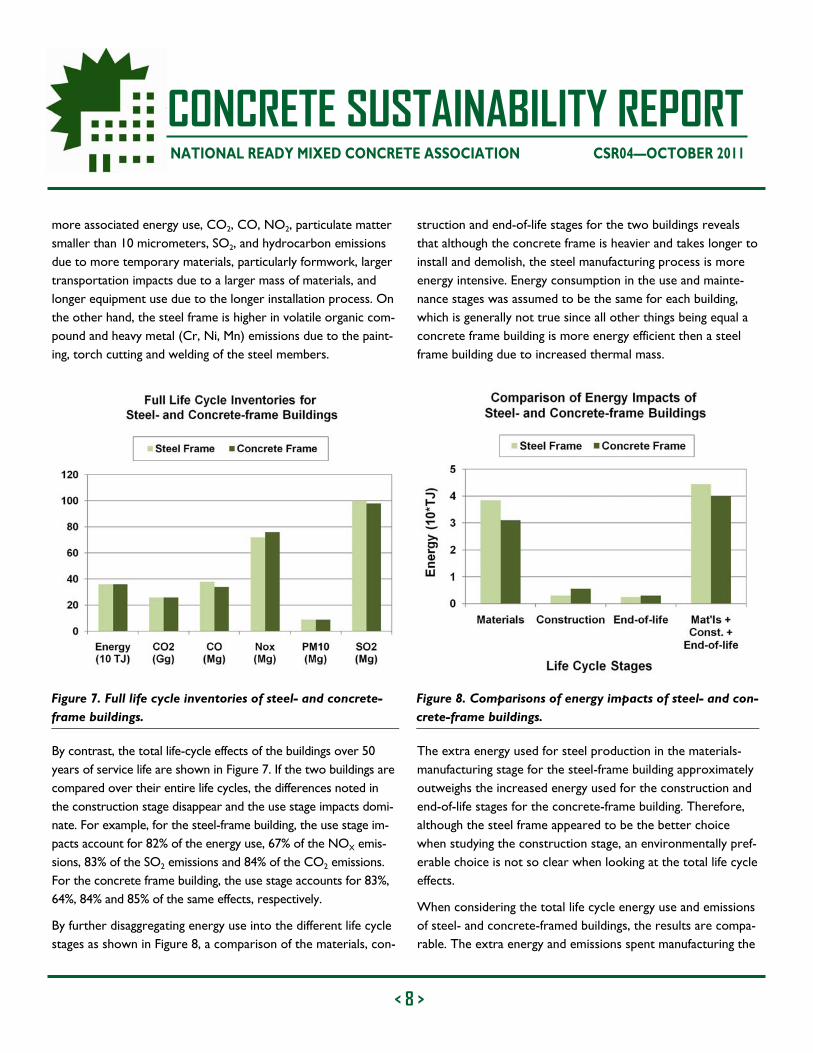
more associated energy use, CO2, CO, NO2, particulate matter smaller than 10 micrometers, SO2, and hydrocarbon emissions due to more temporary materials, particularly formwork, larger transportation impacts due to a larger mass of materials, and longer equipment use due to the longer installation process. On the other hand, the steel frame is higher in volatile organic com-pound and heavy metal (Cr, Ni, Mn) emissions due to the paint-ing, torch cutting and welding of the steel members.
By contrast, the total life-cycle effects of the buildings over 50 years of service life are shown in Figure 7. If the two buildings are compared over their entire life cycles, the differences noted in the construction stage disappear and the use stage impacts domi-nate. For example, for the steel-frame building, the use stage im-pacts account for 82% of the energy use, 67% of the NOX emis-sions, 83% of the SO2 emissions and 84% of the CO2 emissions. For the concrete frame building, the use stage accounts for 83%, 64%, 84% and 85% of the same effects, respectively.
By further disaggregating energy use into the different life cycle stages as shown in Figure 8, a comparison of the materials, con-
struction and end-of-life stages for the two buildings reveals that although the concrete frame is heavier and takes longer to install and demolish, the steel manufacturing process is more energy intensive. Energy consumption in the use and mainte-nance stages was assumed to be the same for each building, which is generally not true since all other things being equal a concrete frame building is more energy efficient then a steel frame building due to increased thermal mass.
The extra energy used for steel production in the materials-manufacturing stage for the steel-frame building approximately outweighs the increased energy used for the construction and end-of-life stages for the concrete-frame building. Therefore, although the steel frame appeared to be the better choice when studying the construction stage, an environmentally pref-erable choice is not so clear when looking at the total life cycle effects.
When considering the total life cycle energy use and emissions of steel- and concrete-framed buildings, the results are compa-rable. The extra energy and emissions spent manufacturing the
Figure 7. Full life cycle inventories of steel- and concrete-frame buildings.
Figure 8. Comparisons of energy impacts of steel- and con-crete-frame buildings.

< 9 >
CONCRETE SUSTAINABILITY REPORT NATIONAL READY MIXED CONCRETE ASSOCIATION CSR04—OCTOBER 2011
structural steel as compared to the concrete are comparable to the extra energy and emissions used to construct and ulti-mately demolish the concrete frame.
Overall, the large use stage environmental effects dwarf every other life cycle stage. For the overall building life cycle, the con-struction stage impacts represent a relatively small part (0.4–11%) of the overall building life cycle energy use and emissions. The maintenance and end-of-life stages also tend to have small contributions to total energy use and emissions. The building use stage contributes the most energy use impacts. This study did not take into account the differences in energy savings over a building’s lifetime from thermal mass and other potential sav-ings such as urban heat island reduction and lighting reduction.
Modeling Energy Performance of Concrete Buildings Marceau and VanGeem conducted research to determine the energy cost savings of concrete-frame buildings versus steel-frame buildings.17 The researchers conducted dynamic whole building energy simulations in six climate zones using DOE2.1E software. They measured energy consumption for a typical 5-
story building with 10 different configurations of exterior walls, structural frames, floors and interior walls as shown in Table 2.
First, the energy analysis was conducted for a baseline building (designation EL in Table 2) as defined in ASHRAE 90.1.18 The base building comprises common, lightweight assemblies with roof insulation entirely above the deck. Above-grade walls are built of metal studs and with exterior insulated finish system (EIFS). Floors are concrete on metal deck supported by steel-joists. The window-to-wall ratio was 0.40 and roof reflectivity was 0.30.
Results show that in all cases, the MMX concrete building simu-lation (see Table 2) demonstrated the lowest energy costs in all six climate zones. The MMX building simulation comprised pre-cast concrete exterior walls exceeding code, reinforced con-crete frame, concrete floors and reinforced concrete interior walls for the building core. Figure 9 provides the cost saving of the MMX building simulation over the EL (base building) for the six different climate zones evaluated. Savings range from 5 to 9% for warm climates like Miami and Phoenix, respectively, 16%
Designation Exterior walls Structural frame Floors Interior walls
EL (baseline) EIFS & metal stud structural steel concrete on metal deck metal stud
CL curtain wall structural steel concrete on metal deck metal stud
ML precast concrete structural steel concrete on metal deck metal stud
EM EIFS & metal stud reinforced concrete 12" (300 mm) solid concrete reinforced concrete
CM curtain wall reinforced concrete 12" (300 mm) solid concrete reinforced concrete
MM precast concrete reinforced concrete 12" (300 mm) solid concrete reinforced concrete
MLX precast concrete exceeding code structural steel concrete on metal deck metal stud
MMX precast concrete exceeding code reinforced concrete 12" (300 mm) solid concrete reinforced concrete
MMI** precast concrete reinforced concrete 12" (300 mm) solid concrete reinforced concrete
MMXI** precast concrete exceeding code reinforced concrete 12" (300 mm) solid concrete reinforced concrete
**High internal load equipment placed near the central core of the building.
Table 2: Building configurations evaluated for energy consumption (adapted from Marceau).

< 10 >
CONCRETE SUSTAINABILITY REPORT NATIONAL READY MIXED CONCRETE ASSOCIATION CSR04—OCTOBER 2011
for a
mild climate like Memphis, 18 to 21% for cold climates like Chi-cago and Denver, respectively and 23% for cool climates like Salem, Oregon.
Life Cycle Assessment of Buildings at the Massachusetts Institute of Technology
Research at the Massachusetts Institute of Technology (MIT) published in a report titled Methods, Impacts, and Opportunities in the Concrete Building Life Cycle explored and advanced key areas relevant to the field of LCA, including methodology, benchmarking and impact reduction.19 A comprehensive LCA was conducted for a benchmark 12-story, 46,321 m2 (498,590 ft2) commercial building. The building was analyzed for two
climates, Phoenix and Chicago, and for two different structural materials, concrete and steel. The annual operating energy, determined using building energy analysis software, was con-ducted for a 60-year life cycle. The Global Warming Potential (GWP) was quantified using CO2 equivalents (CO2e) for several purposes, including benchmarking emissions for current con-struction practices, comparing impacts of concrete versus steel and understanding the relative magnitude of impacts for differ-ent life cycle phases.
The analysis demonstrated that the greenhouse gas emissions due to operational energy of the benchmark buildings are re-sponsible for 95-96% of life cycle emissions. Compared to the
Figure 9. Energy cost savings of concrete-frame buildings (MMX designation in Table 2) over steel-frame buildings (EL designation in Table 2).
Figure 10. Total Global Warming Potential (GWP) over 60-year lifespan for 12-story, 46, 321 m2 (498, 590 ft2) commercial building studied by MIT.

< 11 >
CONCRETE SUSTAINABILITY REPORT NATIONAL READY MIXED CONCRETE ASSOCIATION CSR04—OCTOBER 2011
steel structure, the concrete building has approximately the same embodied emissions (pre-use, maintenance and end-of-life phases), but have lower operating emissions (use phase), which can lead to similar life cycle emissions over time.
For all cases considered, the concrete buildings had similar emissions over 60 years as the steel alternatives. The LCA re-search drew several conclusions, including:
The concrete and steel commercial buildings studied had similar embodied GWP of 205 kg CO2e/m2 (42 lbs CO2e/ft2);
Thermal mass of an exposed concrete frame can provide HVAC savings of 7-9% compared to a steel frame. This accounts for 2% savings in annual operating emissions;
Over a lifetime of 60 years, the CO2e emissions of the concrete building were slightly lower than the steel alter-native (see figure 10); and
The steel and concrete buildings have very similar emis-sions over the full life cycle and the choice of structural material does not dramatically influence the total emis-sions.
Finally, several recommendations for reducing life cycle emis-sions of concrete buildings were presented. In particular, the GWP reduction effects of SCMs in concrete, such as fly ash, were quantified. Additional options for reducing operating
emissions were introduced and quantified within the full life cycle. There are a number of potential emissions reduction strategies for concrete buildings and LCA provides guidance for future environmental improvements, including:
Increasing SCM substitution (such as fly ash) in the con-crete building from 10% to 25% can decrease pre-use GWP for the building by 4.3%; and
Low-lift cooling can decrease the operating energy re-quirements for concrete buildings. Low-lift cooling takes advantage of the high heat capacity of concrete.
Conclusion
Environmental life cycle assessment is a valuable tool for assess-ing the environmental impact of buildings. It is extremely im-portant to include the operational stage of a building life cycle since the operational stage impacts dwarf the impacts of mate-rial extraction, manufacturing, construction and end-of-life life cycle stages. LCA provides a scientific approach to evaluating the merits of design alternatives. For the few LCAs conducted that compare the environmental impacts of steel- and concrete-framed buildings, it has been demonstrated that concrete buildings can offer energy savings and significant reductions in carbon emissions. Concrete building systems combine insula-tion with high thermal mass and low air infiltration to make buildings more energy efficient, therefore reducing the environ-mental impacts of buildings over their entire life cycles.
References
1. ISO 14040 (2006): Environmental management – Life cycle assessment – Principles and framework, International Or-ganisation for Standardisation (ISO), Geneve
2. ISO 14044 (2006): Environmental management – Life cycle assessment – Requirements and guidelines, International Organisation for Standardisation (ISO), Geneve
3. U.S. Environmental Protection Agency, http://www.epa.gov/nrmrl/std/sab/traci/. Accessed April 2011.
4. Energy Information Administration, Annual Energy Outlook 2011, http://www.eia.doe.gov/energyexplained/index.cfm?page=environment_where_ghg_come_from. Accessed April 2011.
5. Marceau, Medgar L., Nisbet, Michael A., and VanGeem, Martha G., Life Cycle Inventory of Portland Cement Concrete, SN3011, Portland Cement Association, Skokie, IL, 2007, 121 pages.

CONCRETE SUSTAINABILITY REPORT
< 12 >
National Ready Mixed Concrete Association
900 Spring Street, Silver Spring, Maryland 20910 888-846-7622 | www.nrmca.org
© National Ready Mixed Concrete Association | All Rights Reserved | October 2011 2PCSR04
NRMCA CSR04
6. National Ready Mixed Concrete Association Sustainability Initiatives, www.nrmca.org/sustainability. Accessed April 2011.
7. Budac, D., Concrete’s Role in the Indoor Air Environment, SN2098, Portland Cement Association, Skokie, IL, 2007.
8. Ferguson, B., Porous Pavements, An Overview. University of Georgia, 1996.
9. Lawrence Berkeley National Laboratory Urban Heat Island Group, http://heatisland.lbl.gov/learn/. Accessed April 2011.
10. LEED 2.2 Reference Guide, United States Green Building Council, 2007.
11. Rosenfeld, A. H.; Akbari, H.; Bretz, S.; Sailor, D.; and Taha, H., Mitigation of Urban Heat Islands: Materials, Utility Pro-grams, and Updates, Submitted to the Journal of Energy Effi-ciency, Vol. 1, No. 1, 1993.
12. Pomerantz, M., Pon, B., Akbari, H. and Chang, S.-C., The Effect of Pavements’ Temperatures on Air Temperatures in Large Cities, Paper LBNL-43442, Lawrence Berkeley Na-tional Laboratory, Berkeley, CA, 2000
13. Rosenfeld, A.H., Romm, J.J., Akbari, H. and Pomerantz, M., Cool Communities: Strategies for Heat Islands Mitigation and Smog Reduction, Energy and Buildings, pp. 51-62, 1998.
14. Akbari, H., and Menon, S., Global Cooling: Effect of Urban Albedo on Global Temperature. Paper for the Proceedings of the International Seminar on Planetary Emergencies. Erice, Sicily, 2007.
15. Jobanputra, W., Influence of Pavement Reflectance on Lighting of Parking Lots. PCA 2458. Portland Cement Association, Skokie, IL, 2005.
16. Guggemos, A. A. and Horvath, A., Comparison of Environ-mental Effects of Steel and Concrete Framed Buildings, ASCE Journal of Infrastructure Systems, June 2005, American Society of Civil Engineers, Reston, VA, 2005.
17. Marceau, M.L, and VanGeem, M.G., Modeling Energy Per-formance of Concrete Buildings for LEED-NC Version 2.2: En-ergy and Atmosphere Credit 1, SN2880a, Portland Cement Association, Skokie, IL, 2007a, 55 pp.
18. ASHRAE, ANSI/ASHRAE/IESNA Standard 90.1-2004, Energy Standard for Buildings Except Low-Rise Residential Buildings, American Society of Heating, Refrigerating, and Air-Conditioning Engineers, Inc., Atlanta, 2004, 191 pp.
19. Ochsendorf, J., et al., Methods, Impacts, and Opportunities in the Concrete Building Life Cycle, Massachusetts Institute of Technology Concrete Sustainability Hub, Cambridge, MA, 2011.


![DESIGN AND EXPERIMENTAL INVESTIGATION ON HIGH ......Brooks et. al. [4] studied the effect of silica fume (SF), metakaolin (MK), flyash and ground granulated blast furnace slag (GGBFS)](https://img.pdfslide.us/doc/110x75/5fe67b629b1ec154305014a3/design-and-experimental-investigation-on-high-brooks-et-al-4-studied.jpg)