Embed Size (px)
Citation preview
1
V 1.0 – Rev. 09.10.07
AASHTO- Load and Resistance Factor Design (LRFD)
Concrete Structures
Bryce Binney, P.E., S.E. and Teddy Theryo, P.E.
Credits
The content for this course has been provided by the following PB employees:
If you have any questions about the content of this courseplease contact Bryce Binney or email [email protected].
2
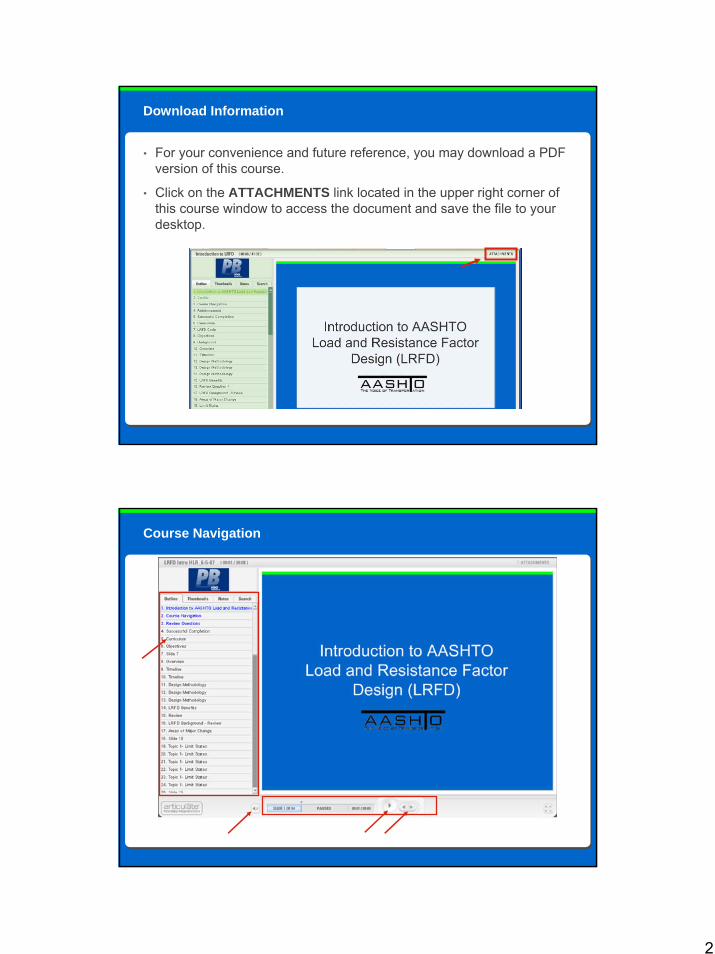
• For your convenience and future reference, you may download a PDF version of this course.
• Click on the ATTACHMENTS link located in the upper right corner of this course window to access the document and save the file to your desktop.
Download Information
Course Navigation

3
Throughout the course review questions are provided. These are designed to reinforce what you have learned in this course and help prepare you for the final assessment. The review scores will not count toward your final grade on the assessment.
Reinforcement
• After completing the content within the course you will be asked to take a final test to ensure that you mastered the key training objectives.
• You will need to make a minimum scoreof 80% on the final assessment to receive credit for passing the course.
• Successful completion of the course will earn 0.1 IACET CEU.
• Please refer to your state’s specific continuing education requirements regarding applicability.
Successful Completion
4
This class is the third class in the Structures TRC curriculum for LRFD Design, developed internally at PB. The curriculum focuses on the following ten areas of major change introduced bythe LRFD Bridge Design Specifications:
• Foundations
• Decks & Deck Systems
• Joints and Bearings
• Abutments, Piers, and Walls
• Railings
• Introduction to LRFD
• Loads and Load Factors
• Concrete Structures
• Steel Structures
• Buried Structures
LRFD Design Curriculum
After completing the training program, you will be able to identify:
1. Reasons for the large size difference between the LRFD and Standard Specification concrete sections
2. The components of “unified” design provisions for concrete members
3. The elements of LRFD shear theories including simplified methods of design, and the Modified Compression Field Theory
4. The concept of strut-and-tie modeling and when it is appropriate
5. Changes to prestressing, including losses and partial prestressing
6. The miscellaneous differences between LRFD and the Standard Specification which may affect everyday design.
Objectives
5
Course Outline
Lesson 1: LRFD Concrete Overview• Introduction to concrete section• Reasons for large size differences Lesson 2: Unified Design• “Unified Design”Lesson 3: Shear Design & Strut and Tie Modeling• Modified Compression Field Theory• Simplified method for shear design• Shear design per the Segmental Specification• Torsion and Shear Friction• Strut & Tie ModelingLesson 4: Prestressing• Partial Prestressing• Prestress lossesLesson 5: Miscellaneous Items
Lesson 1
LRFD Concrete Overview
Narrated by Bryce Binney, P.E., S.E.
Lesson 1
6
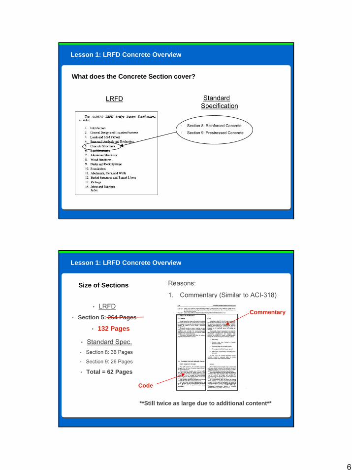
Lesson 1: LRFD Concrete Overview
What does the Concrete Section cover?
LRFD Standard Specification
• Section 8: Reinforced Concrete
• Section 9: Prestressed Concrete
Lesson 1: LRFD Concrete Overview
Size of Sections
• LRFD• Section 5: 264 Pages
• Standard Spec.• Section 8: 36 Pages
• Section 9: 26 Pages
• Total = 62 Pages
Reasons:
1. Commentary (Similar to ACI-318)
Code
Commentary
**Still twice as large due to additional content**
• 132 Pages
7
Lesson 1: LRFD Concrete Overview
Additional Reasons for size differences in sections2. Combination of reinforced and prestressed concrete
3. Lengthy shear provisions (now include torsion)
4. Strut & Tie modeling
5. New provisions for post-tensioning & anchorage zones
6. Seismic provisions specific to concrete
7. Provisions for specific structure typesa. Segmental Construction (AASHTO Guide Specification)
b. Precast girders continuous for live load
c. Precast “spliced” girders
Size of Sections (cont’d)
Lesson 1: LRFD Concrete Overview
What’s New?
Major differences1. Unified design provision which unite reinforced and prestressed components
(flexure & shear)
2. Service design of reinforced concrete is absent (concept of serviceability remains, as well as stress checks for prestressed concrete)
3. Partial prestressing is introduced
4. Shear friction (horizontal shear)
5. No more over-reinforced sections, use smaller φ factor
6. Different equations for prestress losses (for pretensioned concrete)
7. Principle web tension for segmental construction is limited to 3.5√f’c
8. Minimum reinforcing (Mcr)
8
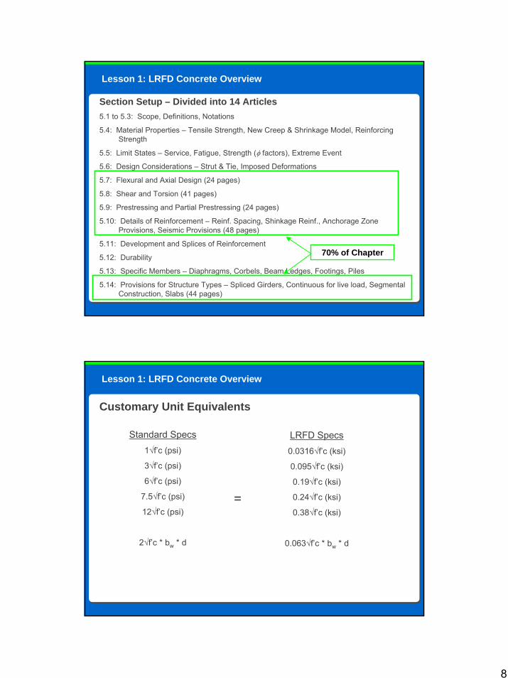
Lesson 1: LRFD Concrete Overview
Section Setup – Divided into 14 Articles5.1 to 5.3: Scope, Definitions, Notations
5.4: Material Properties – Tensile Strength, New Creep & Shrinkage Model, Reinforcing Strength
5.5: Limit States – Service, Fatigue, Strength (φ factors), Extreme Event
5.6: Design Considerations – Strut & Tie, Imposed Deformations
5.7: Flexural and Axial Design (24 pages)
5.8: Shear and Torsion (41 pages)
5.9: Prestressing and Partial Prestressing (24 pages)
5.10: Details of Reinforcement – Reinf. Spacing, Shinkage Reinf., Anchorage Zone Provisions, Seismic Provisions (48 pages)
5.11: Development and Splices of Reinforcement
5.12: Durability
5.13: Specific Members – Diaphragms, Corbels, Beam Ledges, Footings, Piles
5.14: Provisions for Structure Types – Spliced Girders, Continuous for live load, Segmental Construction, Slabs (44 pages)
70% of Chapter
Lesson 1: LRFD Concrete Overview
Customary Unit Equivalents
Standard Specs1√f’c (psi)
3√f’c (psi)
6√f’c (psi)
7.5√f’c (psi)
12√f’c (psi)
2√f’c * bw * d
LRFD Specs0.0316√f’c (ksi)
0.095√f’c (ksi)
0.19√f’c (ksi)
0.24√f’c (ksi)
0.38√f’c (ksi)
0.063√f’c * bw * d
=

9
Course Outline
Lesson 1: LRFD Concrete Overview• Introduction to concrete section• Reasons for large size differences Lesson 2: Unified Design Approach to Structural Concrete• “Unified Design”Lesson 3: Shear Design & Strut and Tie Modeling• Modified Compression Field Theory• Simplified method for shear design• Shear design per the Segmental Specification• Torsion and Shear Friction• Strut & Tie ModelingLesson 4: Prestressing• Partial Prestressing• Prestress lossesLesson 5: Miscellaneous Items
10
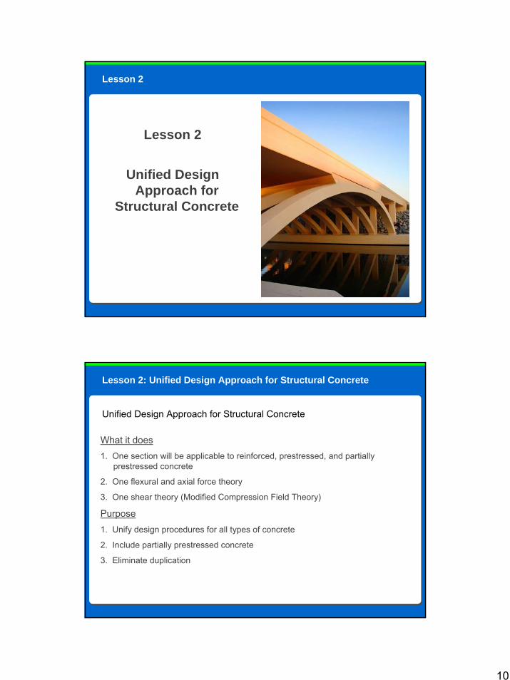
Lesson 2
Lesson 2
Unified Design Approach for
Structural Concrete
Lesson 2: Unified Design Approach for Structural Concrete
What it does1. One section will be applicable to reinforced, prestressed, and partially
prestressed concrete
2. One flexural and axial force theory
3. One shear theory (Modified Compression Field Theory)
Purpose1. Unify design procedures for all types of concrete
2. Include partially prestressed concrete
3. Eliminate duplication
Unified Design Approach for Structural Concrete
11
Lesson 2: Unified Design Approach for Structural Concrete
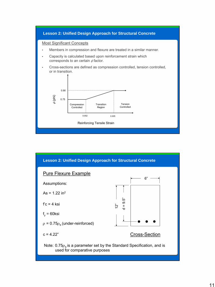
Most Significant Concepts• Members in compression and flexure are treated in a similar manner.
• Capacity is calculated based upon reinforcement strain which corresponds to an certain φ factor.
• Cross-sections are defined as compression controlled, tension controlled, or in transition.
φ(p
hi)
Reinforcing Tensile Strain
0.75
0.90
Compression Controlled
Transition Region
Tension Controlled
0.002 0.005
Lesson 2: Unified Design Approach for Structural Concrete
Pure Flexure Example
Assumptions:
As = 1.22 in2
f’c = 4 ksi
fy = 60ksi
ρ = 0.75ρb (under-reinforced)
c = 4.22”
12”
d =
9.5”
6”
Cross-Section
Note: 0.75ρb is a parameter set by the Standard Specification, and isused for comparative purposes
12
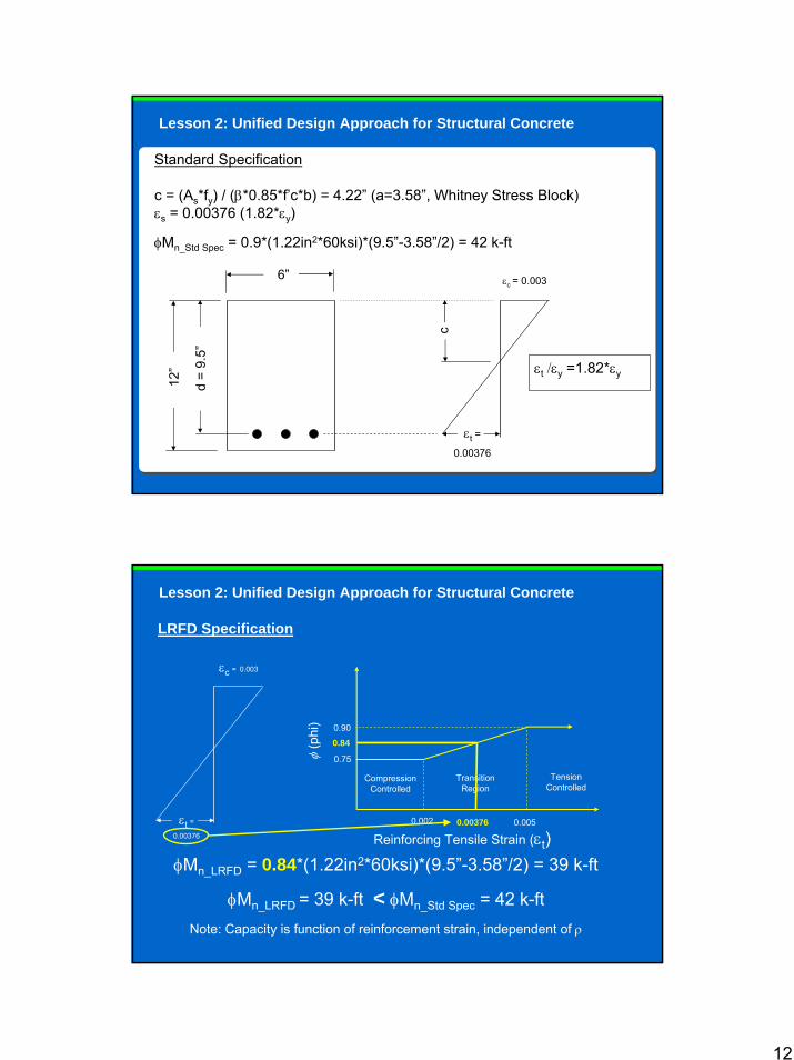
Lesson 2: Unified Design Approach for Structural Concrete
Standard Specification
c = (As*fy) / (β*0.85*f’c*b) = 4.22” (a=3.58”, Whitney Stress Block) εs = 0.00376 (1.82*εy)
φMn_Std Spec = 0.9*(1.22in2*60ksi)*(9.5”-3.58”/2) = 42 k-ft
12”
d =
9.5”
6”
εt =
0.00376
εc = 0.003
εt /εy =1.82*εy
c
LRFD Specification
εt =0.00376
εc = 0.003
φ(p
hi)
Reinforcing Tensile Strain (εt)0.002 0.005
0.75
0.90
Compression Controlled
Transition Region
Tension Controlled
0.00376
0.84
φMn_LRFD = 0.84*(1.22in2*60ksi)*(9.5”-3.58”/2) = 39 k-ft
φMn_LRFD = 39 k-ft < φMn_Std Spec = 42 k-ftNote: Capacity is function of reinforcement strain, independent of ρ
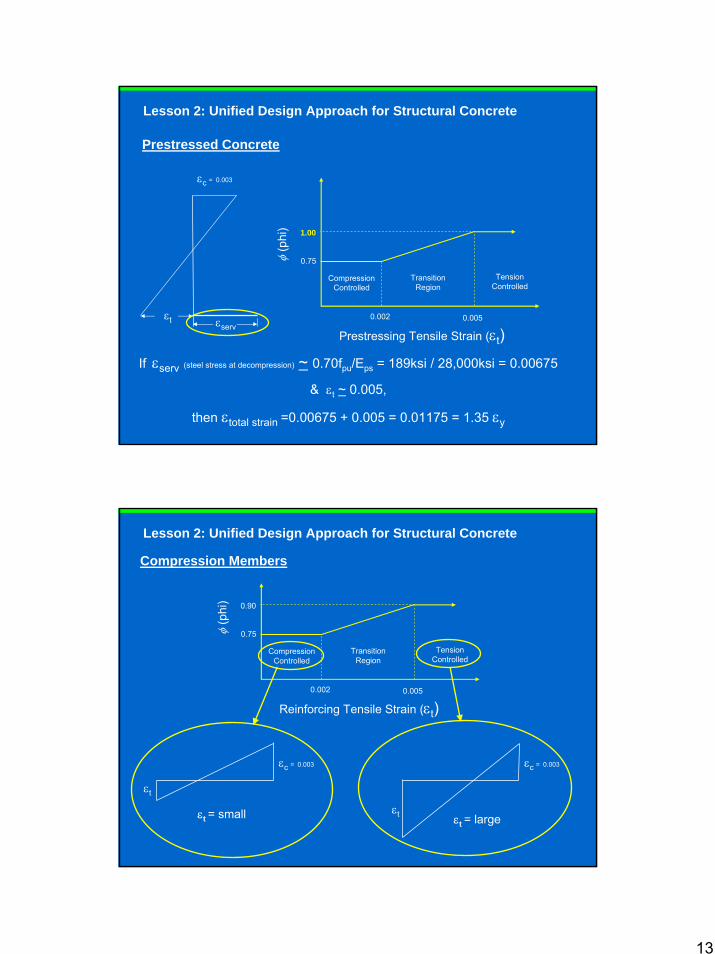
Lesson 2: Unified Design Approach for Structural Concrete
13
Prestressed Concrete
εt
εc = 0.003
φ(p
hi)
Prestressing Tensile Strain (εt)0.002 0.005
0.75
1.00
Compression Controlled
Transition Region
Tension Controlled
If εserv (steel stress at decompression) ~ 0.70fpu/Eps = 189ksi / 28,000ksi = 0.00675
& εt ~ 0.005,
then εtotal strain =0.00675 + 0.005 = 0.01175 = 1.35 εy
εserv
Lesson 2: Unified Design Approach for Structural Concrete
Compression Members
φ(p
hi)
Reinforcing Tensile Strain (εt)0.002 0.005
0.75
0.90
Compression Controlled
Transition Region
Tension Controlled
εc = 0.003
εt
εc = 0.003
εtεt = small εt = large
Lesson 2: Unified Design Approach for Structural Concrete
14
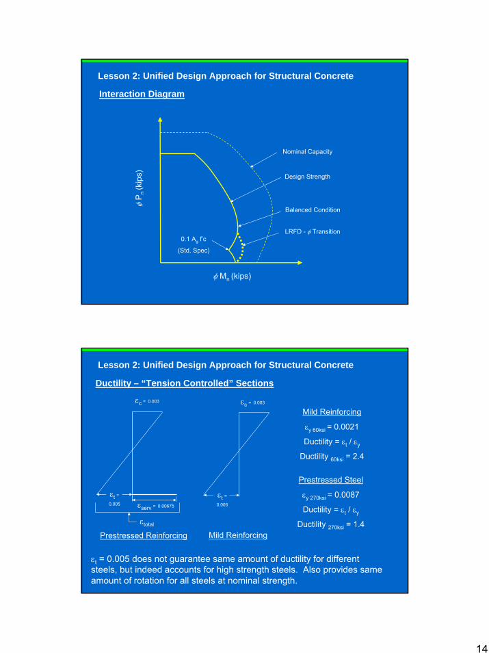
Interaction Diagram
φP
n(k
ips)
φ Mn (kips)
0.1 Ag f’c
(Std. Spec)
LRFD - φ Transition
Balanced Condition
Nominal Capacity
Design Strength
Lesson 2: Unified Design Approach for Structural Concrete
Ductility – “Tension Controlled” Sections
εc = 0.003
εt = 0.005 does not guarantee same amount of ductility for different steels, but indeed accounts for high strength steels. Also provides same amount of rotation for all steels at nominal strength.
εserv = 0.00675
εt =0.005
εt =0.005
εc = 0.003
Mild Reinforcing
εy 60ksi = 0.0021
Ductility = εt / εy
Ductility 60ksi = 2.4
Prestressed Steel
εy 270ksi = 0.0087
Ductility = εt / εy
Ductility 270ksi = 1.4εtotal
Mild ReinforcingPrestressed Reinforcing
Lesson 2: Unified Design Approach for Structural Concrete
15
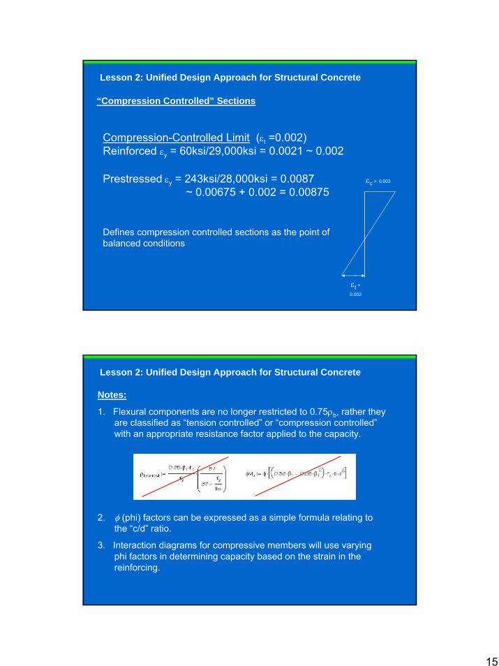
Compression-Controlled Limit (εt =0.002)Reinforced εy = 60ksi/29,000ksi = 0.0021 ~ 0.002
Prestressed εy = 243ksi/28,000ksi = 0.0087 ~ 0.00675 + 0.002 = 0.00875
Defines compression controlled sections as the point of balanced conditions
“Compression Controlled” Sections
εt =0.002
εc = 0.003
Lesson 2: Unified Design Approach for Structural Concrete
Notes:
1. Flexural components are no longer restricted to 0.75ρb, rather they are classified as “tension controlled” or “compression controlled”with an appropriate resistance factor applied to the capacity.
2. φ (phi) factors can be expressed as a simple formula relating to the “c/d” ratio.
3. Interaction diagrams for compressive members will use varying phi factors in determining capacity based on the strain in the reinforcing.
Lesson 2: Unified Design Approach for Structural Concrete

16
Course Outline
Lesson 1: LRFD Concrete Overview• Introduction to chapter• Reasons for large size differences Lesson 2: Unified Design• “Unified Design”Lesson 3: Shear Design & Strut and Tie Modeling• Modified Compression Field Theory• Simplified method for shear design• Shear design per the Segmental Specification• Torsion and Shear Friction• Strut & Tie ModelingLesson 4: Prestressing• Partial Prestressing• Prestress lossesLesson 5: Miscellaneous Items
17
Lesson 3
Shear Design & Strut and Tie Modeling
Lesson 3
Lesson 3 – Shear Design & Strut and Tie Modeling
Shear Design: (LRFD - 3 ways to determine capacity)1. Modified Compression Field Theory
2. Simplified method for shear design (NCHRP 549)
3. Shear design per the AASHTO Guide Specification for Design and Construction of Segmental Concrete Bridges
Other Topics1. Torsion
2. Horizontal Shear (Shear Friction)
3. Strut & Tie modeling (deep beams)
Lesson 3 Overview
18
Method 1 - Modified Compression Field Theory
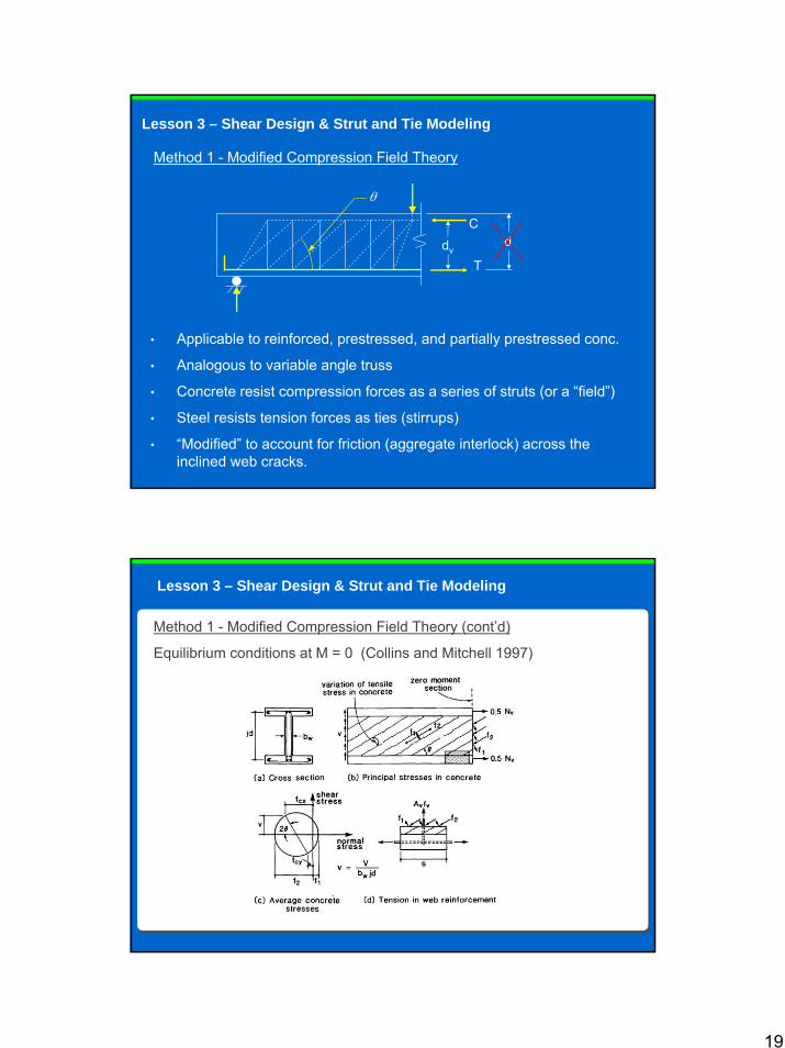
Method 1 - Modified Compression Field Theory
• Ritter (1899), also Morsch (1902) defined shear behavior in cracked concrete analogous to truss behavior
• Both assumed a 45 degree inclination of compression struts
• From this, Vecchio and Collins have expanded the theory into what it is today
θ
C
T
Lesson 3 – Shear Design & Strut and Tie Modeling
19
Method 1 - Modified Compression Field Theory
• Applicable to reinforced, prestressed, and partially prestressed conc.
• Analogous to variable angle truss
• Concrete resist compression forces as a series of struts (or a “field”)
• Steel resists tension forces as ties (stirrups)
• “Modified” to account for friction (aggregate interlock) across the inclined web cracks.
θ
C
Tdv
Lesson 3 – Shear Design & Strut and Tie Modeling
d
Lesson 3 – Shear Design & Strut and Tie Modeling
Method 1 - Modified Compression Field Theory (cont’d)
Equilibrium conditions at M = 0 (Collins and Mitchell 1997)
20
Lesson 3 – Shear Design & Strut and Tie Modeling
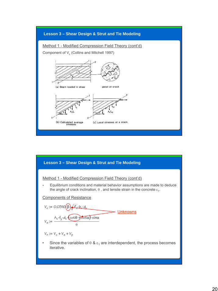
Method 1 - Modified Compression Field Theory (cont’d)Component of Vc (Collins and Mitchell 1997)
Lesson 3 – Shear Design & Strut and Tie Modeling
Method 1 - Modified Compression Field Theory (cont’d)• Equilibrium conditions and material behavior assumptions are made to deduce
the angle of crack inclination, θ , and tensile strain in the concrete ε1.
Components of Resistance
Unknowns
• Since the variables of θ & ε1 are interdependent, the process becomes iterative.
21
Lesson 3 – Shear Design & Strut and Tie Modeling
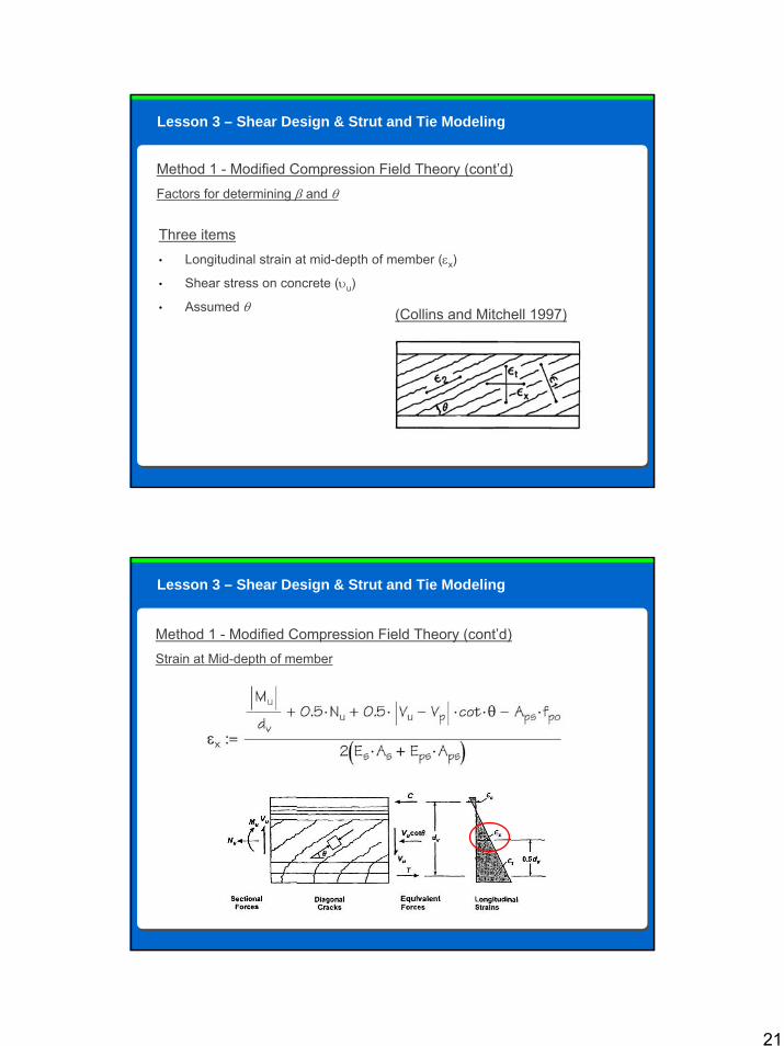
Method 1 - Modified Compression Field Theory (cont’d)Factors for determining β and θ
Three items• Longitudinal strain at mid-depth of member (εx)
• Shear stress on concrete (υu)
• Assumed θ (Collins and Mitchell 1997)
Lesson 3 – Shear Design & Strut and Tie Modeling
Method 1 - Modified Compression Field Theory (cont’d)Strain at Mid-depth of member
22
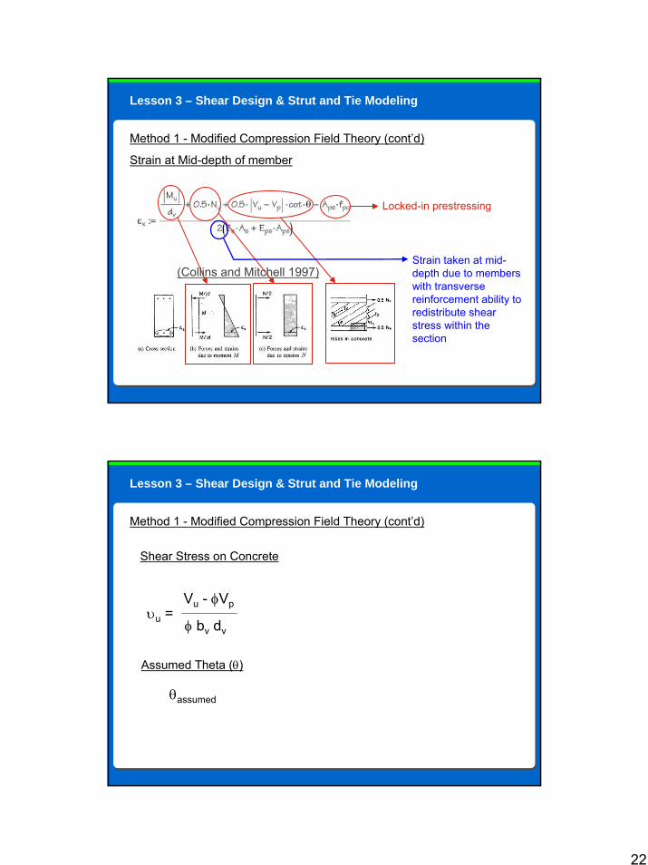
Method 1 - Modified Compression Field Theory (cont’d)
Strain at Mid-depth of member
Strain taken at mid-depth due to members with transverse reinforcement ability to redistribute shear stress within the section
Locked-in prestressing
Lesson 3 – Shear Design & Strut and Tie Modeling
(Collins and Mitchell 1997)
Method 1 - Modified Compression Field Theory (cont’d)
υu =Vu - φVp
φ bv dv
Shear Stress on Concrete
θassumed
Assumed Theta (θ)
Lesson 3 – Shear Design & Strut and Tie Modeling
23
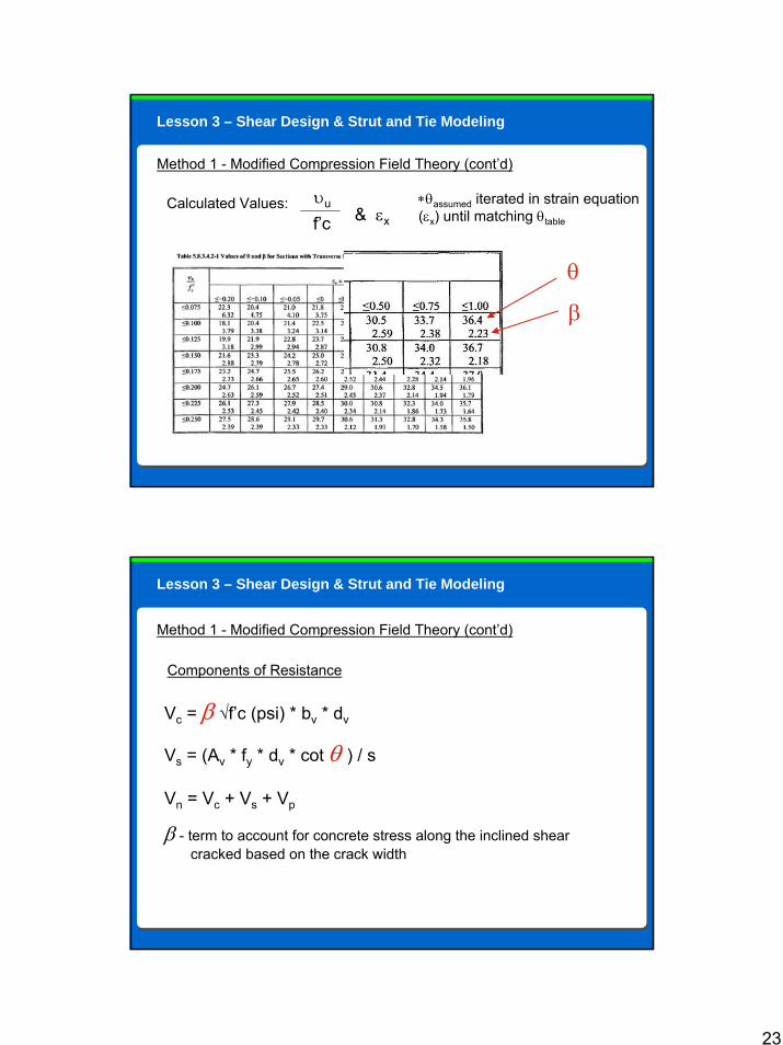
Method 1 - Modified Compression Field Theory (cont’d)
υuCalculated Values:& εxf’c
∗θassumed iterated in strain equation (εx) until matching θtable
θ
β
Lesson 3 – Shear Design & Strut and Tie Modeling
Method 1 - Modified Compression Field Theory (cont’d)
Components of Resistance
Vc = β √f’c (psi) * bv * dv
Vs = (Av * fy * dv * cot θ ) / s
Vn = Vc + Vs + Vp
β - term to account for concrete stress along the inclined shear cracked based on the crack width
Lesson 3 – Shear Design & Strut and Tie Modeling
24
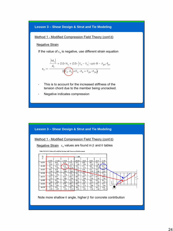
Method 1 - Modified Compression Field Theory (cont’d)
Negative Strain
If the value of εx is negative, use different strain equation
• This is to account for the increased stiffness of the tension chord due to the member being uncracked.
• Negative indicates compression
Lesson 3 – Shear Design & Strut and Tie Modeling
Method 1 - Modified Compression Field Theory (cont’d)
Negative Strain εx values are found in β and θ tables
Note more shallow θ angle, higher β for concrete contribution
Lesson 3 – Shear Design & Strut and Tie Modeling
25
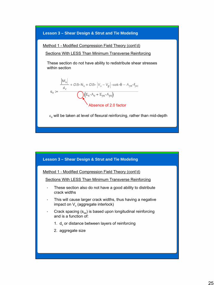
Method 1 - Modified Compression Field Theory (cont’d)
Sections With LESS Than Minimum Transverse Reinforcing
εx will be taken at level of flexural reinforcing, rather than mid-depth
These section do not have ability to redistribute shear stresseswithin section
Absence of 2.0 factor
Lesson 3 – Shear Design & Strut and Tie Modeling
Method 1 - Modified Compression Field Theory (cont’d)
Sections With LESS Than Minimum Transverse Reinforcing
• These section also do not have a good ability to distribute crack widths
• This will cause larger crack widths, thus having a negative impact on Vc (aggregate interlock)
• Crack spacing (sxe) is based upon longitudinal reinforcing and is a function of:
1. dv or distance between layers of reinforcing
2. aggregate size
Lesson 3 – Shear Design & Strut and Tie Modeling
26
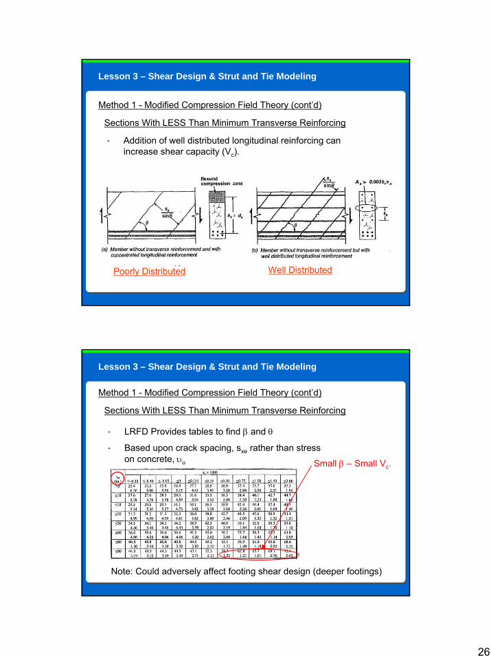
Method 1 - Modified Compression Field Theory (cont’d)
Sections With LESS Than Minimum Transverse Reinforcing
• Addition of well distributed longitudinal reinforcing can increase shear capacity (Vc).
Lesson 3 – Shear Design & Strut and Tie Modeling
Poorly Distributed Well Distributed
Method 1 - Modified Compression Field Theory (cont’d)
Sections With LESS Than Minimum Transverse Reinforcing
• LRFD Provides tables to find β and θ
• Based upon crack spacing, sxe rather than stress on concrete, υu Small β – Small Vc.
Note: Could adversely affect footing shear design (deeper footings)
Lesson 3 – Shear Design & Strut and Tie Modeling
27
Method 1 - Modified Compression Field Theory (cont’d)
Two more important issues
• Minimum longitudinal reinforcing (equilibrium)
• Maximum allowable shear stress on a cross section
Lesson 3 – Shear Design & Strut and Tie Modeling
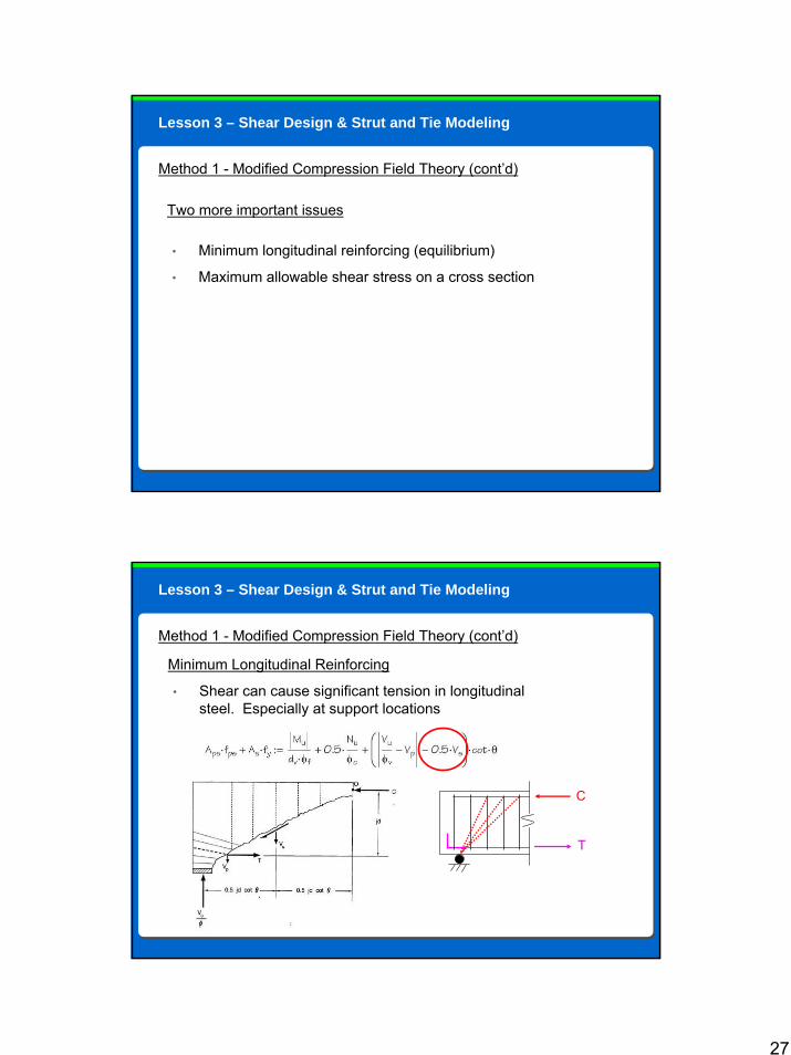
Method 1 - Modified Compression Field Theory (cont’d)
Minimum Longitudinal Reinforcing
• Shear can cause significant tension in longitudinal steel. Especially at support locations
Lesson 3 – Shear Design & Strut and Tie Modeling
C
T
28
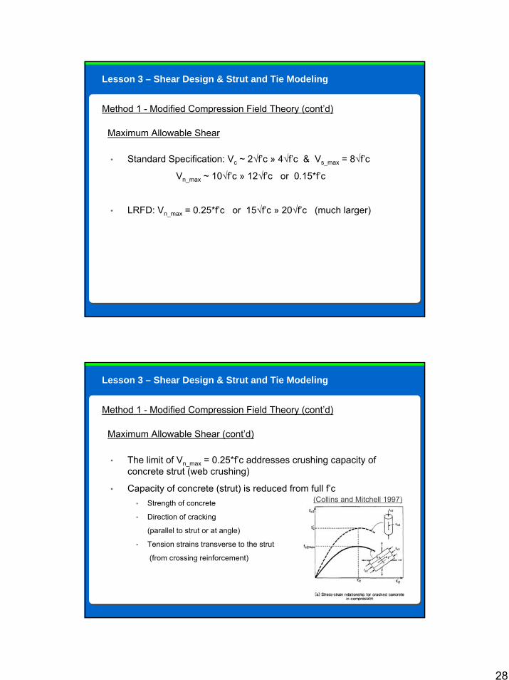
Method 1 - Modified Compression Field Theory (cont’d)
Maximum Allowable Shear
• Standard Specification: Vc ~ 2√f’c » 4√f’c & Vs_max = 8√f’c
Vn_max ~ 10√f’c » 12√f’c or 0.15*f’c
• LRFD: Vn_max = 0.25*f’c or 15√f’c » 20√f’c (much larger)
Lesson 3 – Shear Design & Strut and Tie Modeling
Method 1 - Modified Compression Field Theory (cont’d)
Maximum Allowable Shear (cont’d)
• The limit of Vn_max = 0.25*f’c addresses crushing capacity of concrete strut (web crushing)
• Capacity of concrete (strut) is reduced from full f’c• Strength of concrete
• Direction of cracking
(parallel to strut or at angle)
• Tension strains transverse to the strut
(from crossing reinforcement)
Lesson 3 – Shear Design & Strut and Tie Modeling
(Collins and Mitchell 1997)

29
Course Outline
Lesson 1: LRFD Concrete Overview• Introduction to concrete section• Reasons for large size differences Lesson 2: Unified Design• “Unified Design”Lesson 3: Shear Design & Strut and Tie Modeling• Modified Compression Field Theory• MCFT Subset - Simplified method for non-prestressed sections• Simplified method for shear design• Shear design per the Segmental Specification• Torsion and Shear Friction• Strut & Tie ModelingLesson 4: Prestressing• Partial Prestressing• Prestress lossesLesson 5: Miscellaneous Items
30
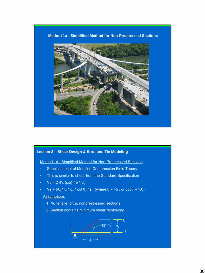
Method 1a - Simplified Method for Non-Prestressed Sections
Method 1a - Simplified Method for Non-Prestressed Sections
• Special subset of Modified Compression Field Theory
• This is similar to shear from the Standard Specification
• Vc = 2√f’c (psi) * b * dv
• Vs = (Av * fy * dv * cot θ) / s (where θ = 45 , or cot θ = 1.0)
45°
dv
C
Tdv
Assumptions
1. No tensile force, nonprestressed sections
2. Section contains minimum shear reinforcing
Lesson 3 – Shear Design & Strut and Tie Modeling
31
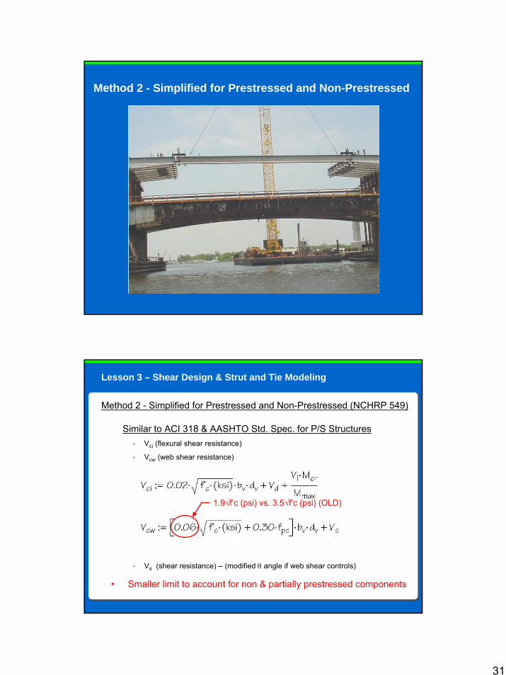
Method 2 - Simplified for Prestressed and Non-Prestressed
Method 2 - Simplified for Prestressed and Non-Prestressed (NCHRP 549)
Similar to ACI 318 & AASHTO Std. Spec. for P/S Structures• Vci (flexural shear resistance)
• Vcw (web shear resistance)
• Vs (shear resistance) – (modified θ angle if web shear controls)
1.9√f’c (psi) vs. 3.5√f’c (psi) (OLD)
• Smaller limit to account for non & partially prestressed components
Lesson 3 – Shear Design & Strut and Tie Modeling
32
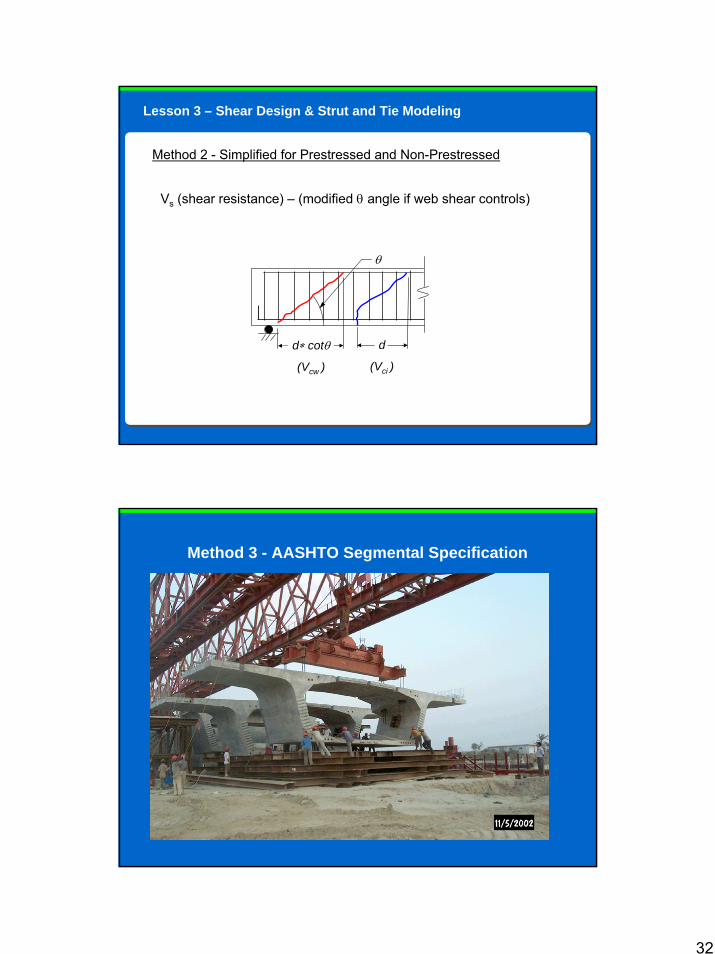
Method 2 - Simplified for Prestressed and Non-Prestressed
θ
d∗ cotθ
(Vcw )
d
(Vci )
Vs (shear resistance) – (modified θ angle if web shear controls)
Lesson 3 – Shear Design & Strut and Tie Modeling
Method 3 - AASHTO Segmental Specification
33
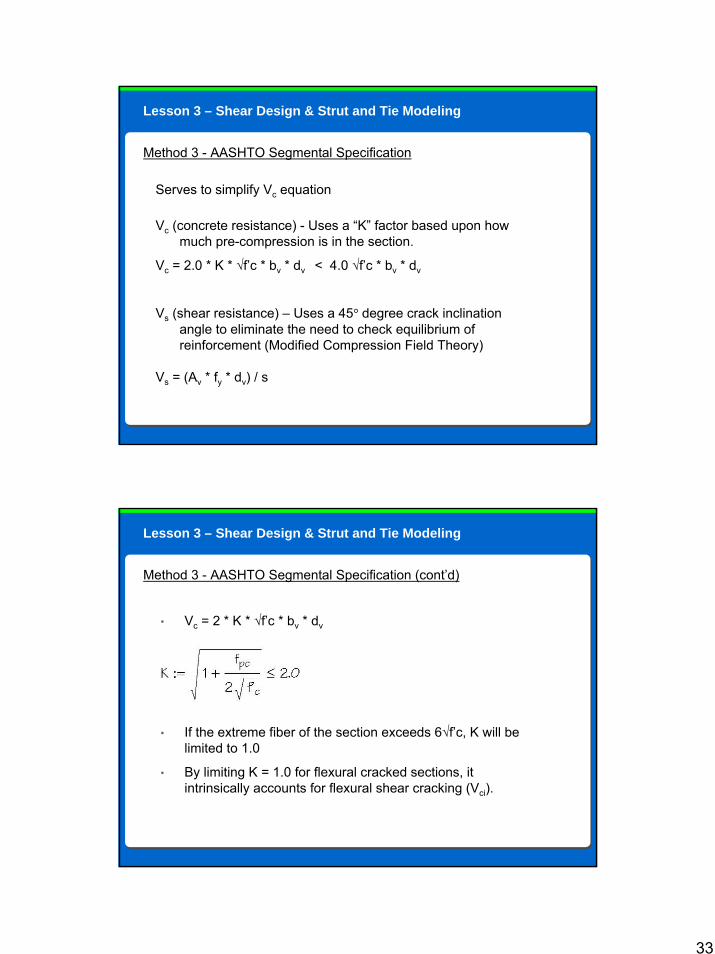
Method 3 - AASHTO Segmental Specification
Serves to simplify Vc equation
Vc (concrete resistance) - Uses a “K” factor based upon how much pre-compression is in the section.
Vc = 2.0 * K * √f’c * bv * dv < 4.0 √f’c * bv * dv
Vs (shear resistance) – Uses a 45° degree crack inclination angle to eliminate the need to check equilibrium of reinforcement (Modified Compression Field Theory)
Vs = (Av * fy * dv) / s
Lesson 3 – Shear Design & Strut and Tie Modeling
• Vc = 2 * K * √f’c * bv * dv
• If the extreme fiber of the section exceeds 6√f’c, K will be limited to 1.0
• By limiting K = 1.0 for flexural cracked sections, it intrinsically accounts for flexural shear cracking (Vci).
Method 3 - AASHTO Segmental Specification (cont’d)
Lesson 3 – Shear Design & Strut and Tie Modeling
34
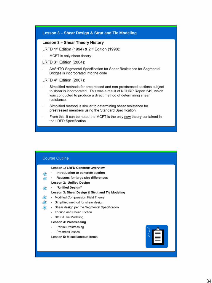
Lesson 3 – Shear Design & Strut and Tie Modeling
LRFD 1st Edition (1994) & 2nd Edition (1998):• MCFT is only shear theory
Lesson 3 – Shear Theory History
LRFD 3rd Edition (2004):• AASHTO Segmental Specification for Shear Resistance for Segmental
Bridges is incorporated into the code
LRFD 4th Edition (2007):• Simplified methods for prestressed and non-prestressed sections subject
to shear is incorporated. This was a result of NCHRP Report 549, which was conducted to produce a direct method of determining shear resistance.
• Simplified method is similar to determining shear resistance forprestressed members using the Standard Specification
• From this, it can be noted the MCFT is the only new theory contained in the LRFD Specification
Course Outline
Lesson 1: LRFD Concrete Overview• Introduction to concrete section• Reasons for large size differences Lesson 2: Unified Design• “Unified Design”Lesson 3: Shear Design & Strut and Tie Modeling• Modified Compression Field Theory• Simplified method for shear design• Shear design per the Segmental Specification• Torsion and Shear Friction• Strut & Tie ModelingLesson 4: Prestressing• Partial Prestressing• Prestress lossesLesson 5: Miscellaneous Items
35
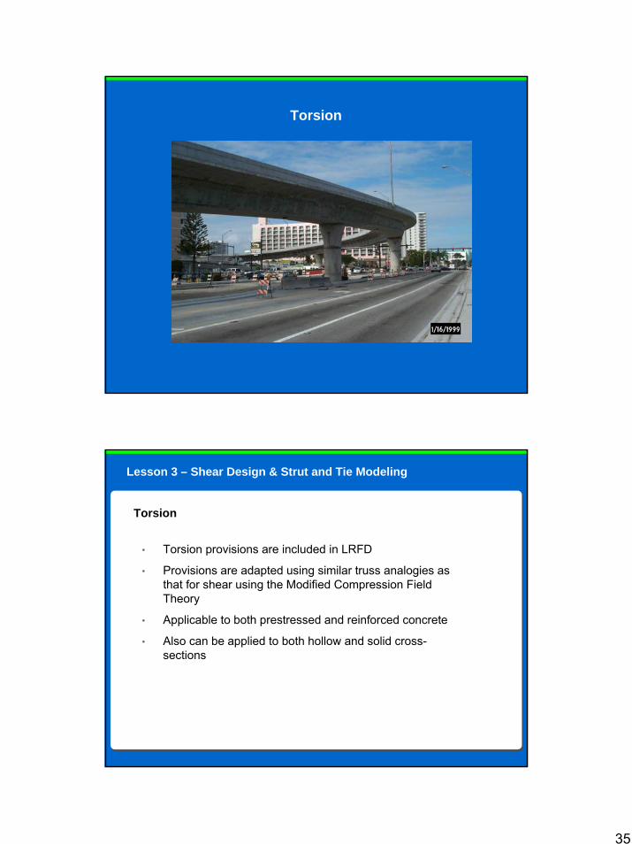
Torsion
• Torsion provisions are included in LRFD
• Provisions are adapted using similar truss analogies as that for shear using the Modified Compression Field Theory
• Applicable to both prestressed and reinforced concrete
• Also can be applied to both hollow and solid cross-sections
Torsion
Lesson 3 – Shear Design & Strut and Tie Modeling
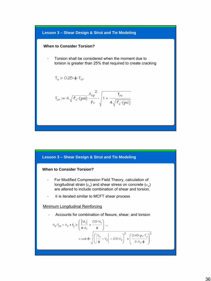
36
• Torsion shall be considered when the moment due to torsion is greater than 25% that required to create cracking
When to Consider Torsion?
Lesson 3 – Shear Design & Strut and Tie Modeling
• For Modified Compression Field Theory, calculation of longitudinal strain (εx) and shear stress on concrete (υu) are altered to include combination of shear and torsion.
• θ is iterated similar to MCFT shear process
When to Consider Torsion?
Minimum Longitudinal Reinforcing
• Accounts for combination of flexure, shear, and torsion
Lesson 3 – Shear Design & Strut and Tie Modeling
37
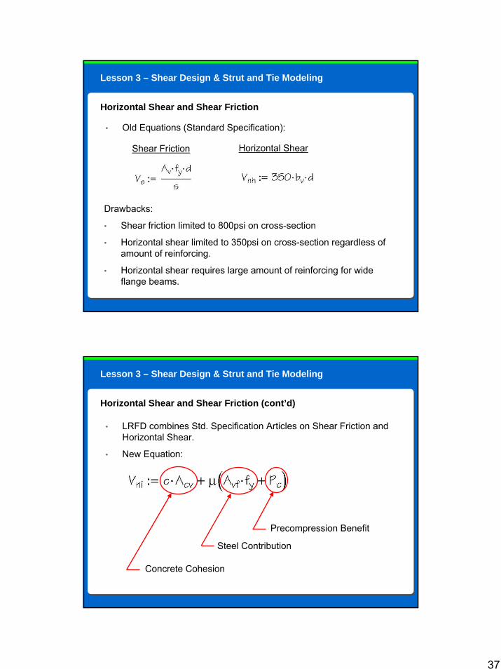
• Old Equations (Standard Specification):
Horizontal Shear and Shear Friction
Shear Friction Horizontal Shear
Drawbacks:
• Shear friction limited to 800psi on cross-section
• Horizontal shear limited to 350psi on cross-section regardless of amount of reinforcing.
• Horizontal shear requires large amount of reinforcing for wide flange beams.
Lesson 3 – Shear Design & Strut and Tie Modeling
• LRFD combines Std. Specification Articles on Shear Friction and Horizontal Shear.
• New Equation:
Horizontal Shear and Shear Friction (cont’d)
Concrete Cohesion
Steel Contribution
Precompression Benefit
Lesson 3 – Shear Design & Strut and Tie Modeling

38
Benefits:
• Accounts for concrete cohesion
• Takes advantage of precompression benefits
• Shear friction has higher limits of max nominal shear stress (upto 1800psi from old limit of 800psi)
• Uses a more rational approach for horiz. shear, considering quantity of steel crossing the plane, rather than blindly using 350psi.
• Horiz. shear will require less steel for wide flange beams, since Av > 50psi*Ac can be waived if φVni > 1.33Vui / φ
Horizontal Shear and Shear Friction (cont’d)
Lesson 3 – Shear Design & Strut and Tie Modeling
39
Course Outline
Lesson 1: LRFD Concrete Overview• Introduction to concrete section• Reasons for large size differences Lesson 2: Unified Design• “Unified Design”Lesson 3: Shear Design & Strut and Tie Modeling• Modified Compression Field Theory• Simplified method for shear design• Shear design per the Segmental Specification• Torsion and Shear Friction• Strut & Tie ModelingLesson 4: Prestressing• Partial Prestressing• Prestress lossesLesson 5: Miscellaneous Items
Strut & Tie Modeling
40
• New section in code (Article 5.6.3)
• Used to determine internal force effects at regions near supports and locations of concentrated loads
• Used in “disturbed” regions or those where plane section do notremain plane
What is a strut and tie model?
• A design tool used to determine the flow of forces through a member
• Uses equilibrium conditions at strength limits
• Relies on concrete providing compression “struts” and reinforcing providing tension “ties” to resist internal forces
• Compression struts and tension ties meet at nodal locations
Strut & Tie Modeling
Lesson 3 – Shear Design & Strut and Tie Modeling
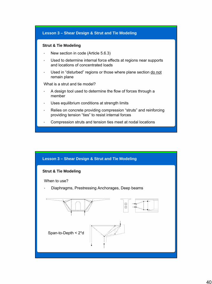
Strut & Tie Modeling
When to use?
• Diaphragms, Prestressing Anchorages, Deep beams
Span-to-Depth < 2*d
Lesson 3 – Shear Design & Strut and Tie Modeling
41
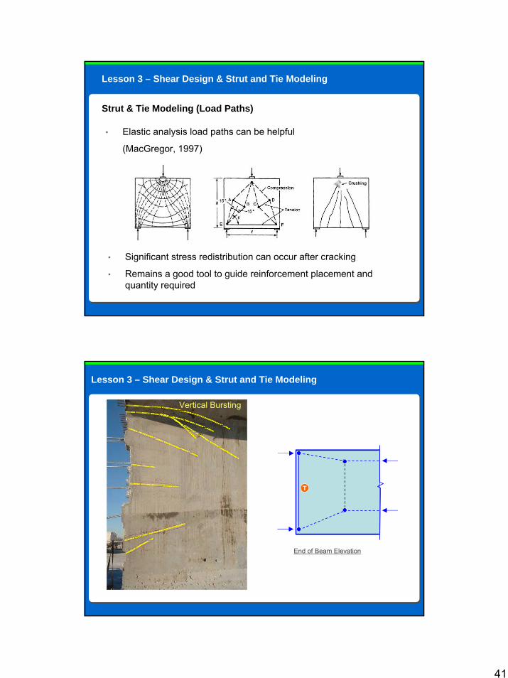
Strut & Tie Modeling (Load Paths)
• Significant stress redistribution can occur after cracking
• Remains a good tool to guide reinforcement placement and quantity required
• Elastic analysis load paths can be helpful
(MacGregor, 1997)
Lesson 3 – Shear Design & Strut and Tie Modeling
Vertical Bursting
P
P
P
P
≅ 0.6H ≅ 0.4H
3”
1.75”11.5”
26.5”
End of Beam Elevation
T
Lesson 3 – Shear Design & Strut and Tie Modeling
42
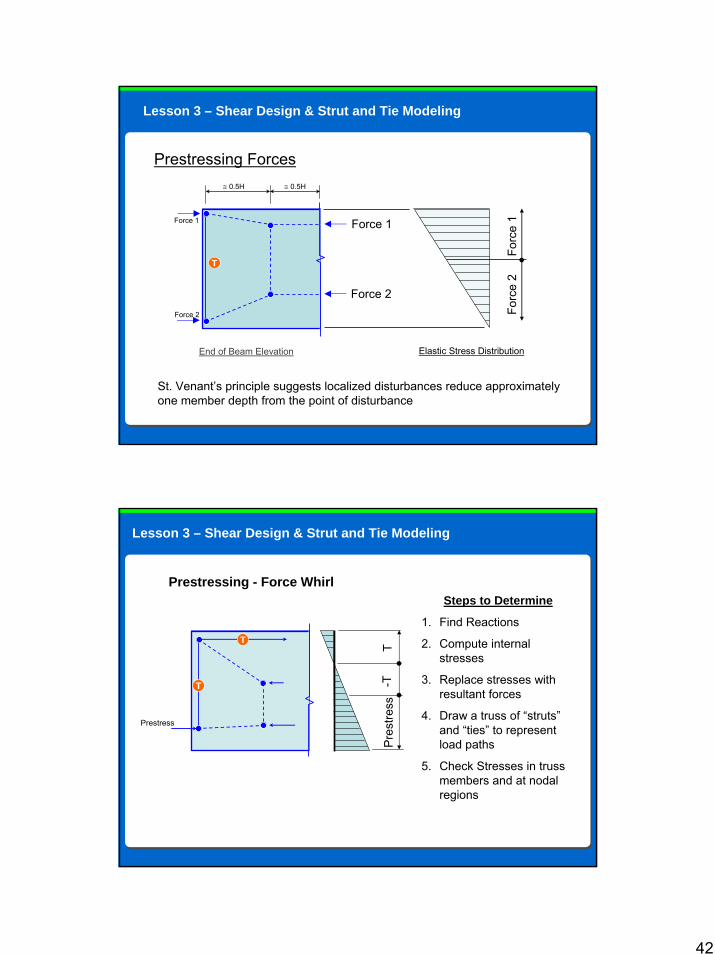
Prestressing Forces
Force 1
Force 2
P
P
≅ 0.5H ≅ 0.5H
3”
1.75”11.5”
26.5”
End of Beam Elevation
T
Force 1
Force 2
Elastic Stress Distribution
Forc
e 1
Forc
e 2
St. Venant’s principle suggests localized disturbances reduce approximately one member depth from the point of disturbance
Lesson 3 – Shear Design & Strut and Tie Modeling
Prestressing - Force Whirl
T
T
Prestress
2nd Stage P/T
Stage 1 & P/S
T-T
Pre
stre
ss
Steps to Determine
1. Find Reactions
2. Compute internal stresses
3. Replace stresses with resultant forces
4. Draw a truss of “struts”and “ties” to represent load paths
5. Check Stresses in truss members and at nodal regions
Lesson 3 – Shear Design & Strut and Tie Modeling
43
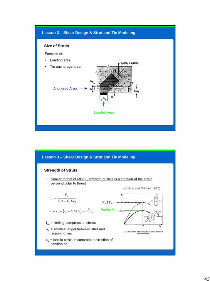
Size of Struts
2nd Stage P/T
Stage 1 & P/S
Loaded Area
Anchored Area
Function of:
• Loading area
• Tie anchorage area
Lesson 3 – Shear Design & Strut and Tie Modeling
Strength of Struts
2nd Stage P/T
Stage 1 & P/S
• Similar to that of MCFT, strength of strut is a function of the strain perpendicular to thrust
fcu = limiting compression stress
αs = smallest angel between strut and adjoining ties
εs = tensile strain in concrete in direction of tension tie
Partial f’c
Full f’c
Lesson 3 – Shear Design & Strut and Tie Modeling
(Collins and Mitchell 1997)
44
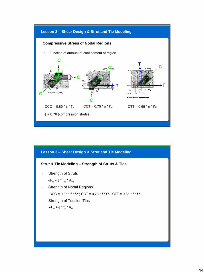
Compressive Stress of Nodal Regions
2nd Stage P/T
• Function of amount of confinement of region
C
C
C
C
C
C
T T
T
CCC = 0.85 * φ * f’c CCT = 0.75 * φ * f’c CTT = 0.65 * φ * f’c
φ = 0.70 (compression struts)
Lesson 3 – Shear Design & Strut and Tie Modeling
• Strength of Struts
φPn = φ * fcu * Acs
• Strength of Nodal Regions
CCC = 0.85 * f * f’c ; CCT = 0.75 * f * f’c ; CTT = 0.65 * f * f’c
• Strength of Tension TiesφPn = φ * fy * Ast
Strut & Tie Modeling – Strength of Struts & Ties
Lesson 3 – Shear Design & Strut and Tie Modeling

45
• Structures designed using strut and tie models are required to contain an orthogonal grid of reinforcing at each face to control cracking.
• Spacing not to exceed 12inches
• Ratio of reinforcing to gross area shall be 0.003 in each direction
Strut & Tie Modeling – Crack Control Reinforcement
Lesson 3 – Shear Design & Strut and Tie Modeling
46
Course Outline
Lesson 1: LRFD Concrete Overview• Introduction to concrete section• Reasons for large size differences Lesson 2: Unified Design• “Unified Design”Lesson 3: Shear Design & Strut and Tie Modeling• Modified Compression Field Theory• Simplified method for shear design• Shear design per the Segmental Specification• Torsion and Shear Friction• Strut & Tie ModelingLesson 4: Prestressing• Partial Prestressing• Prestress lossesLesson 5: Miscellaneous Items
Lesson 4
Lesson 4
Prestressing
47
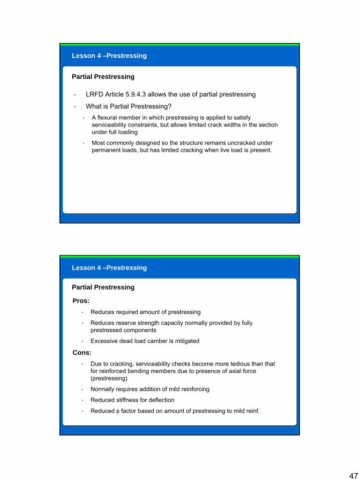
• LRFD Article 5.9.4.3 allows the use of partial prestressing
• What is Partial Prestressing?• A flexural member in which prestressing is applied to satisfy
serviceability constraints, but allows limited crack widths in the section under full loading
• Most commonly designed so the structure remains uncracked under permanent loads, but has limited cracking when live load is present.
Partial Prestressing
Lesson 4 –Prestressing
Pros:• Reduces required amount of prestressing
• Reduces reserve strength capacity normally provided by fully prestressed components
• Excessive dead load camber is mitigated
Cons:• Due to cracking, serviceability checks become more tedious than that
for reinforced bending members due to presence of axial force (prestressing)
• Normally requires addition of mild reinforcing
• Reduced stiffness for deflection
• Reduced φ factor based on amount of prestressing to mild reinf.
Partial Prestressing
Lesson 4 –Prestressing
48
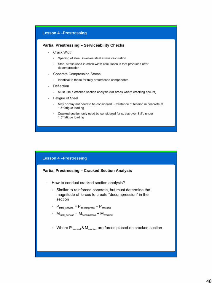
• Crack Width• Spacing of steel, involves steel stress calculation
• Steel stress used in crack width calculation is that produced after decompression
• Concrete Compression Stress• Identical to those for fully prestressed components
• Deflection• Must use a cracked section analysis (for areas where cracking occurs)
• Fatigue of Steel• May or may not need to be considered - existence of tension in concrete at
1.5*fatigue loading
• Cracked section only need be considered for stress over 3√f’c under 1.5*fatigue loading
Partial Prestressing – Serviceability Checks
Lesson 4 –Prestressing
• How to conduct cracked section analysis?
• Similar to reinforced concrete, but must determine the magnitude of forces to create “decompression” in the section
• Ptotal_service = Pdecompress + Pcracked
• Mtotal_service = Mdecompress + Mcracked
• Where Pcracked & Mcracked are forces placed on cracked section
Partial Prestressing – Cracked Section Analysis
Lesson 4 –Prestressing
49
Partial Prestressing – Cracked Section Analysis, cont.
Steps to Determine Stresses and Strains1. Calculate σ and ε at transfer
2. Changes in σ and ε due to creep, shrinkage, relaxation
3. Changes in σ and ε due to decompression (opposite of 1 + 2)
4. Changes in σ and ε in the cracked stage• (Mcracked = Mtotal_service – Mdecompress) & (Pcracked = Ptotal_service – Pdecompress)
• Calculate compression block depth (third order equation)
5. Sum strains in reinforcing
Note: Curvature of section will be the summation of Steps 1 to 4
Lesson 4 –Prestressing
Prestress Losses
50
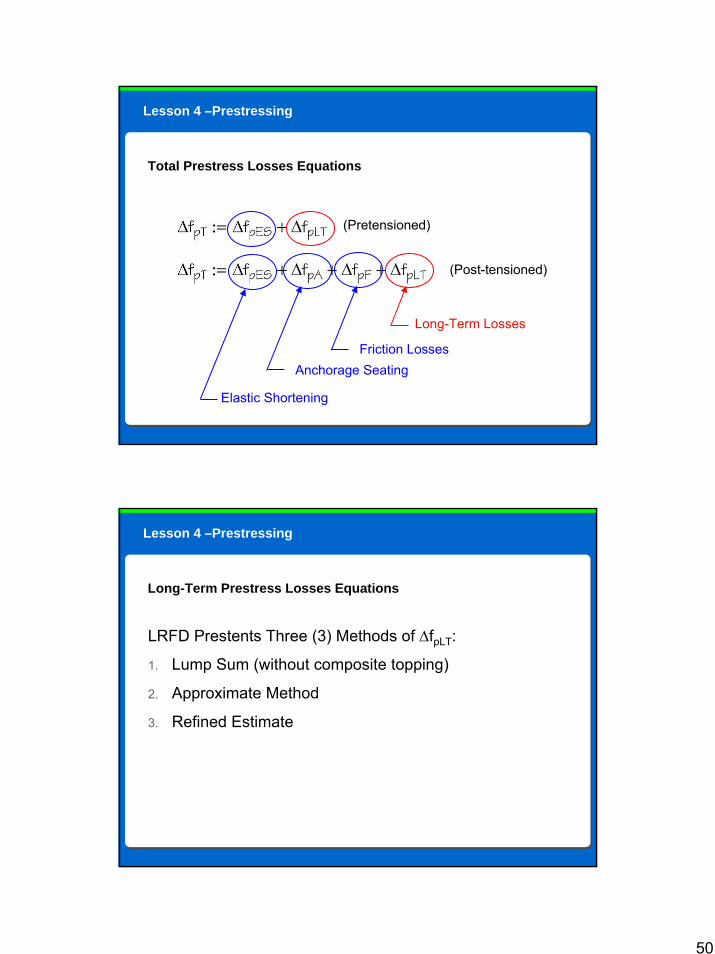
Total Prestress Losses Equations
(Pretensioned)
(Post-tensioned)
Elastic Shortening
Anchorage SeatingFriction Losses
Long-Term Losses
Lesson 4 –Prestressing
Long-Term Prestress Losses Equations
LRFD Prestents Three (3) Methods of ∆fpLT:
1. Lump Sum (without composite topping)
2. Approximate Method
3. Refined Estimate
Lesson 4 –Prestressing
51
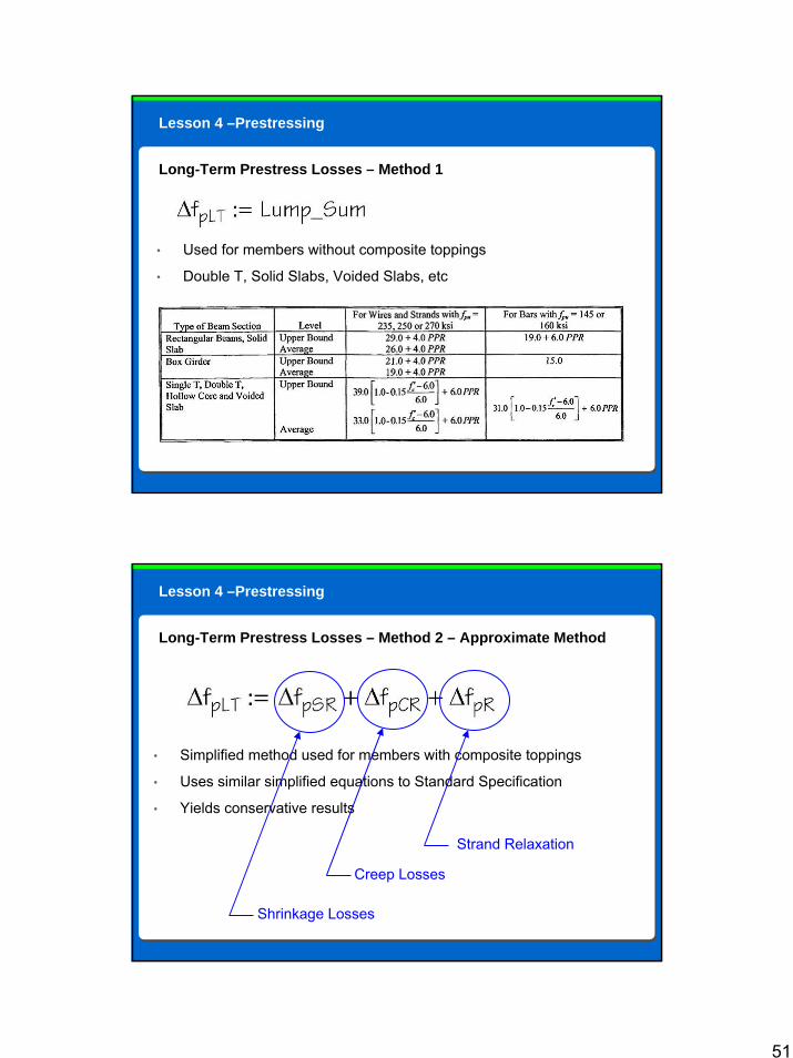
Long-Term Prestress Losses – Method 1
• Used for members without composite toppings
• Double T, Solid Slabs, Voided Slabs, etc
Lesson 4 –Prestressing
Long-Term Prestress Losses – Method 2 – Approximate Method
• Simplified method used for members with composite toppings
• Uses similar simplified equations to Standard Specification
• Yields conservative results
Shrinkage Losses
Creep Losses
Strand Relaxation
Lesson 4 –Prestressing
52
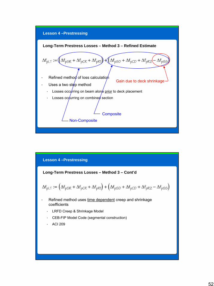
Long-Term Prestress Losses – Method 3 – Refined Estimate
• Refined method of loss calculation
• Uses a two step method• Losses occurring on beam alone prior to deck placement
• Losses occurring on combined section
Non-CompositeComposite
Gain due to deck shrinkage
Lesson 4 –Prestressing
Long-Term Prestress Losses – Method 3 – Cont’d
• Refined method uses time dependent creep and shrinkage coefficients
• LRFD Creep & Shrinkage Model
• CEB-FIP Model Code (segmental construction)
• ACI 209
Lesson 4 –Prestressing

53
Course Outline
Lesson 1: LRFD Concrete Overview• Introduction to concrete section• Reasons for large size differences Lesson 2: Unified Design• “Unified Design”Lesson 3: Shear Design & Strut and Tie Modeling• Modified Compression Field Theory• Simplified method for shear design• Shear design per the Segmental Specification• Torsion and Shear Friction• Shear Theories (including Strut & Tie)Lesson 4: Prestressing• Partial Prestressing• Prestress lossesLesson 5: Miscellaneous Items
54
Lesson 5
Lesson 5
Miscellaneous Items
• Non-Linear Temp. Gradient
• Minimum Flexural Reinforcing
• Minimum Shear Reinforcing
• Span-to-Depth Ratios
• Crack Width (“z” factor)
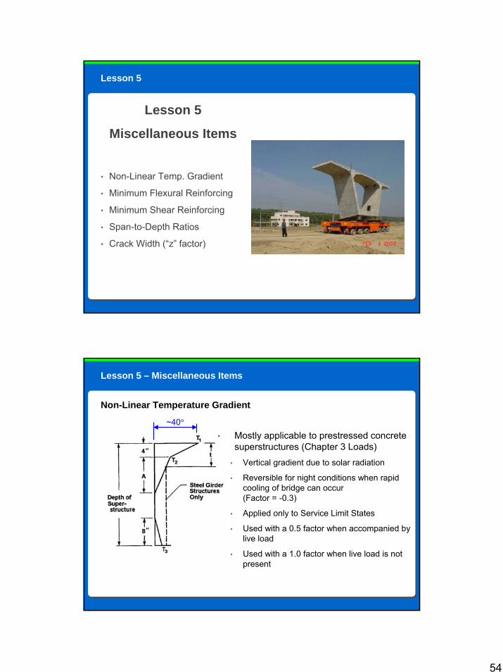
Non-Linear Temperature Gradient
• Mostly applicable to prestressed concrete superstructures (Chapter 3 Loads)
• Vertical gradient due to solar radiation
• Reversible for night conditions when rapid cooling of bridge can occur (Factor = -0.3)
• Applied only to Service Limit States
• Used with a 0.5 factor when accompanied by live load
• Used with a 1.0 factor when live load is not present
~40°
Lesson 5 – Miscellaneous Items
55
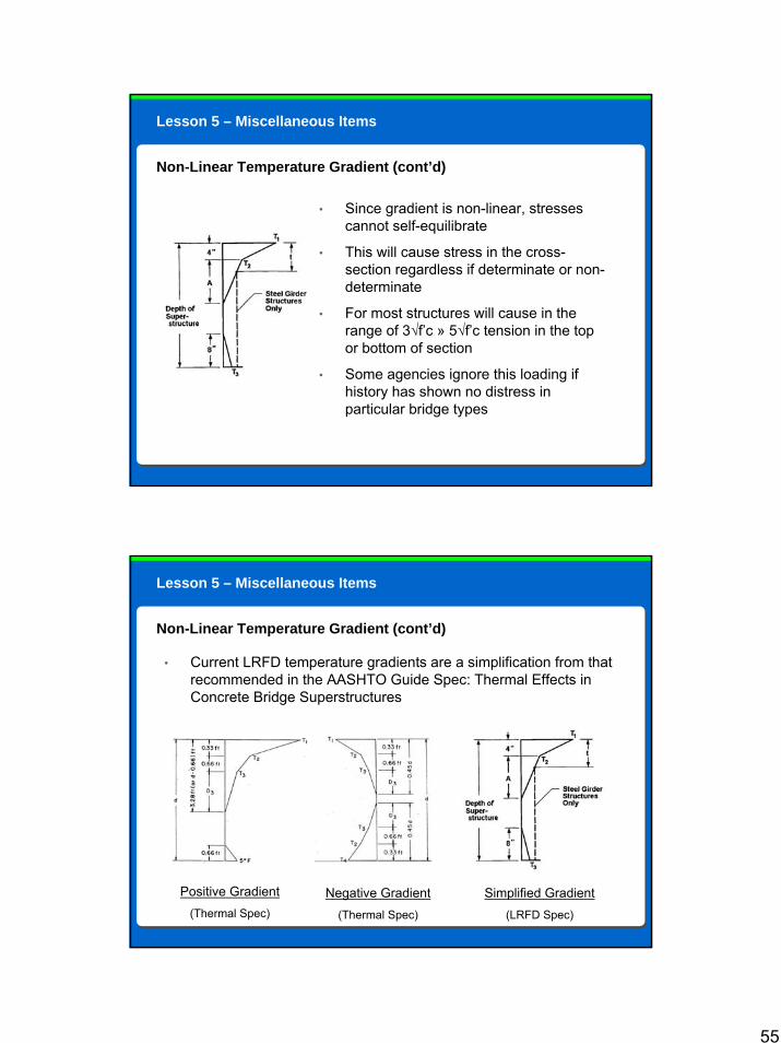
Non-Linear Temperature Gradient (cont’d)
• Since gradient is non-linear, stresses cannot self-equilibrate
• This will cause stress in the cross-section regardless if determinate or non-determinate
• For most structures will cause in the range of 3√f’c » 5√f’c tension in the top or bottom of section
• Some agencies ignore this loading if history has shown no distress in particular bridge types
Lesson 5 – Miscellaneous Items
Lesson 5 – Miscellaneous Items
Non-Linear Temperature Gradient (cont’d)
• Current LRFD temperature gradients are a simplification from that recommended in the AASHTO Guide Spec: Thermal Effects in Concrete Bridge Superstructures
Positive Gradient(Thermal Spec)
Negative Gradient(Thermal Spec)
Simplified Gradient(LRFD Spec)
56
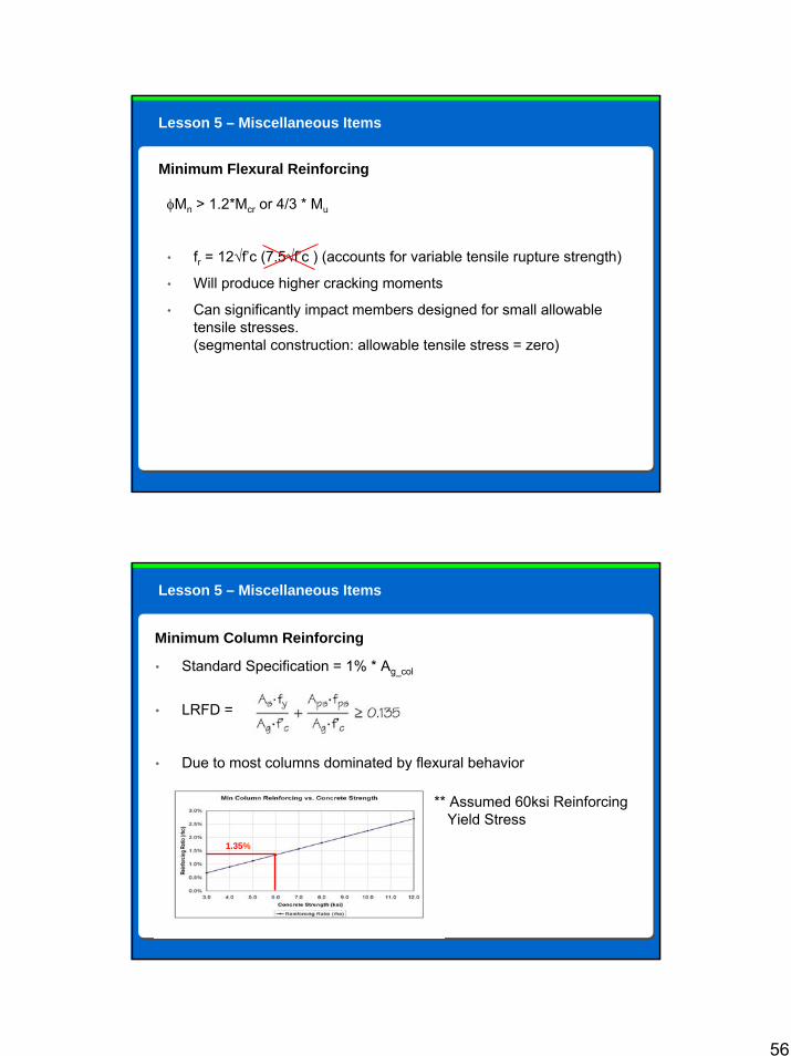
Minimum Flexural Reinforcing
φMn > 1.2*Mcr or 4/3 * Mu
• fr = 12√f’c (7.5√f’c ) (accounts for variable tensile rupture strength)
• Will produce higher cracking moments
• Can significantly impact members designed for small allowable tensile stresses. (segmental construction: allowable tensile stress = zero)
Lesson 5 – Miscellaneous Items
Lesson 5 – Miscellaneous Items
Minimum Column Reinforcing
• Standard Specification = 1% * Ag_col
• LRFD =
• Due to most columns dominated by flexural behavior
1.35%
** Assumed 60ksi Reinforcing Yield Stress
57
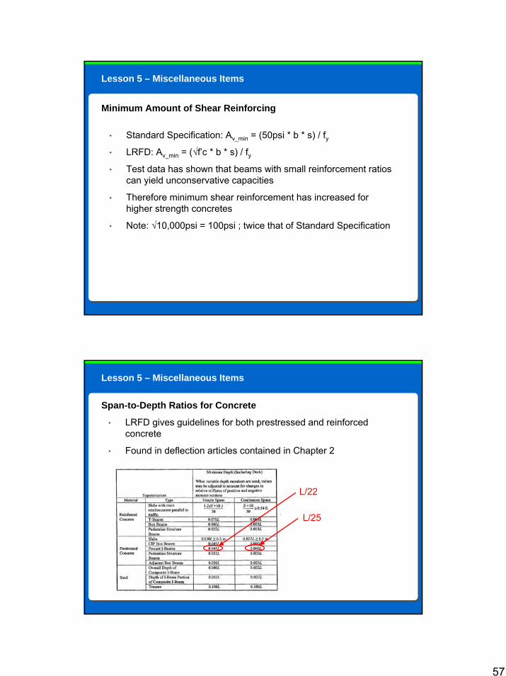
Minimum Amount of Shear Reinforcing
• Standard Specification: Av_min = (50psi * b * s) / fy• LRFD: Av_min = (√f’c * b * s) / fy• Test data has shown that beams with small reinforcement ratios
can yield unconservative capacities
• Therefore minimum shear reinforcement has increased for higher strength concretes
• Note: √10,000psi = 100psi ; twice that of Standard Specification
Lesson 5 – Miscellaneous Items
Lesson 5 – Miscellaneous Items
Span-to-Depth Ratios for Concrete
• LRFD gives guidelines for both prestressed and reinforced concrete
• Found in deflection articles contained in Chapter 2
L/22
L/25
58
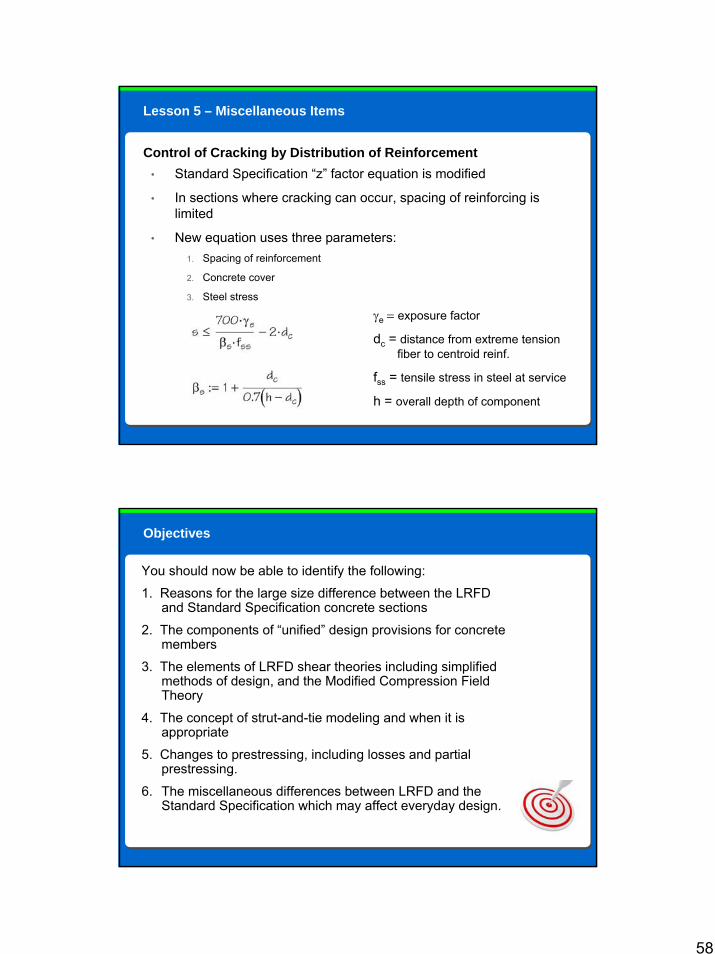
Lesson 5 – Miscellaneous Items
Control of Cracking by Distribution of Reinforcement• Standard Specification “z” factor equation is modified
• In sections where cracking can occur, spacing of reinforcing is limited
• New equation uses three parameters:1. Spacing of reinforcement
2. Concrete cover
3. Steel stress
γe = exposure factor
dc = distance from extreme tension fiber to centroid reinf.
fss = tensile stress in steel at service
h = overall depth of component
You should now be able to identify the following:
1. Reasons for the large size difference between the LRFD and Standard Specification concrete sections
2. The components of “unified” design provisions for concrete members
3. The elements of LRFD shear theories including simplified methods of design, and the Modified Compression Field Theory
4. The concept of strut-and-tie modeling and when it is appropriate
5. Changes to prestressing, including losses and partial prestressing.
6. The miscellaneous differences between LRFD and the Standard Specification which may affect everyday design.
Objectives
59
References
• AASHTO, “Standard Specifications for Highway Bridges,” 17th Edition, American Association of State Highway and Transportation Officials, Washington D.C., 2002.
• AASHTO, “LRFD Bridge Design Specifications,” 4th Edition, American Association of State Highway and Transportation Officials, Washington D.C., 2007.
• Collins, M.P., and Mitchell, D. (1980), “Shear and Torsion Design of Prestressed and Non-Prestressed Concrete Beams,” Journal of the Prestressed Concrete Institute, V. 25, No. 5, Sept.-Oct., pp. 32-100.
• Collins, M.P., and Mitchell, D., Prestressed Concrete Structures, Response Publications, Canada, 1997.
• Ghali, A., Favre, R., and Elbadry, M., Concrete Structures, 3rd Edition, E & FN Spon, London, 2002.
• MacGregor, James G., Reinforced Concrete, Prentice Hall, New Jersey, 1997.
• Vecchio, F.J., and Collins, M.P., “The Modified Compression-Field Theory for Reinforced Concrete Elements Subjected to Shear,” ACI Structural Journal, V. 83, No. 2, Mar.-Apr. 1986, pp. 219-231.
The following references were used in the preparation of this course.
Instructions
• The assessment consists of 10 multiple choice questions.
• You will need to achieve a minimum score of 80% to receive credit for passing the course.
• If you score below 80%, please go back and review the content of this course, and then retake the assessment to achieve a passing score.
You are now ready to begin the final assessment.
When ready, click the Right arrow below to advance to the assessment.
Final Assessment

60
Thank you for completing this course. If you received a passing score on the assessment, simply close this window to exit the course. Your score will be recorded on your transcript.
If you did not achieve a passing score, please review the content of this course and then retake the assessment to achieve a passing score.
If you have any questions or problems with the functionality of this course, please email us at [email protected] and specify the name of the course and the issue you are experiencing so that we may assist you.
Conclusion


![[XLS]ondemandweb.pbworld.netondemandweb.pbworld.net/pbucontent/RV-Course... · Web viewConcrete Additives: Water ... the condition of the concrete in a structure relating the](https://img.pdfslide.us/doc/110x75/5ad274d67f8b9a72118d2ae3/xls-viewconcrete-additives-water-the-condition-of-the-concrete-in-a-structure.jpg)