Embed Size (px)
Citation preview

1
Concrete Strength Testing
Techniciandeveloped by:
The University of Arkansas, Dept. of Civil Engineering
in conjunction with
The Arkansas Department of Transportation
Basic Aggregates Certification
Renewal• 5 Year Certification
• To prevent expiration :
o Take online Basic Aggregates Certification Renewal course
o Pass final quiz after all online modules are
complete
o Cost - $0
o Extends Basic Aggregates Certification for 5 years
• If not completed prior to expiration date, other
CTTP certifications will be suspended
o Soils, Hot-Mix Asphalt, NPDES, Concrete Field, Concrete Strength
2
2
Course Topics
• ASTM C 617 (T 231)o Capping Cylindrical Concrete Specimens
• ASTM C 1231o Use of Unbonded Caps in Determination of
Compressive Strength of Hardened Concrete Cylinders
• ASTM C 39 (T 22)o Compressive Strength of Cylindrical Concrete
Specimens
• ASTM C 78 (T 97)o Flexural Strength of Concrete
3
Concrete Strength Testing
Certification Program• 5 Year Certification
o Written Exam
o Performance Exam
• Failure of Either Examo Requires retake of failed exam within 1 year
• Entire written exam
• Entire performance exam
• If date is missed, student must retake both exams
o Student is responsible for rescheduling of retake
4
3
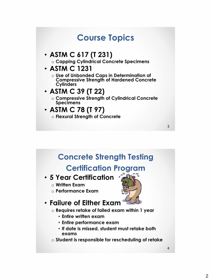
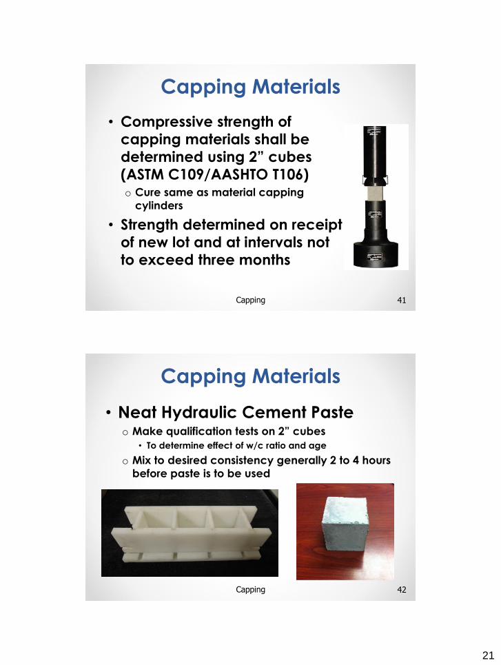
Written Exam
• Questionso Standards
o Special Applications
• ~ 40 Questionso Multiple Choice
o True / False
o At least 8 questions
on each of the test
methods
• Limitationso 1 Hour Exam
o Closed Book
• Passing
Requirementso 60 % Each Standard
o 70 % Overall
5
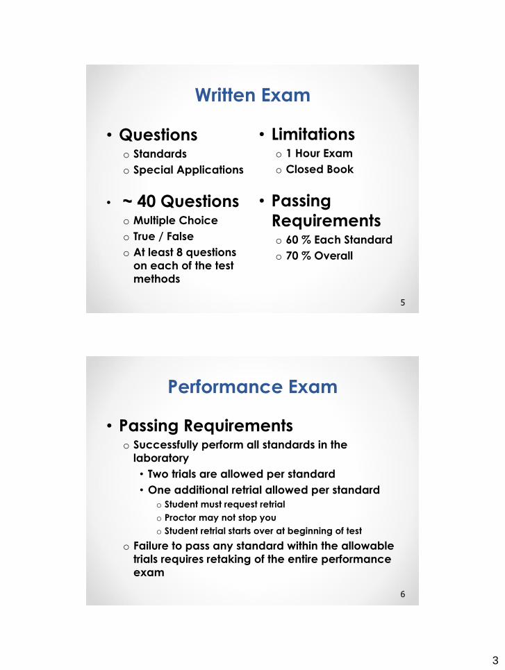
Performance Exam
• Passing Requirementso Successfully perform all standards in the
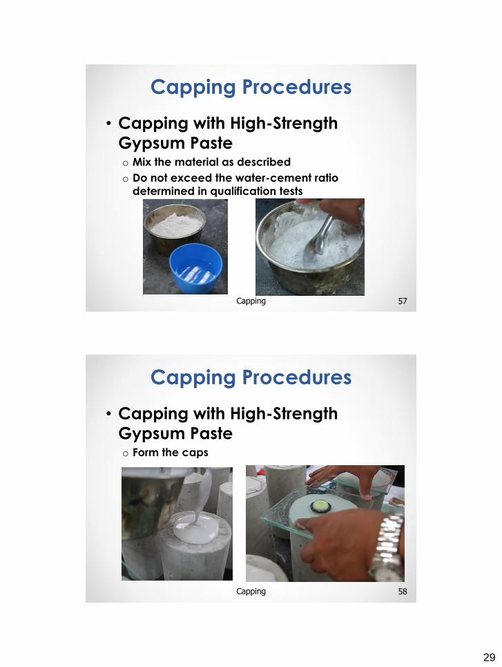
laboratory
• Two trials are allowed per standard
• One additional retrial allowed per standard
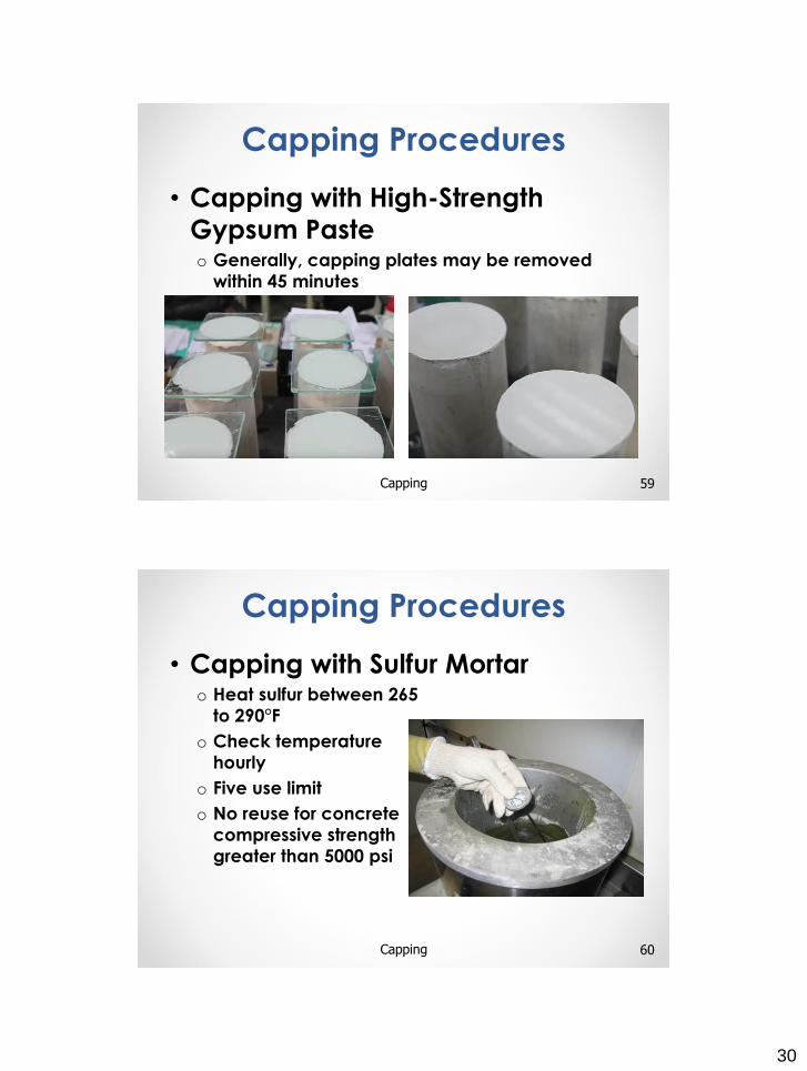
o Student must request retrial
o Proctor may not stop you
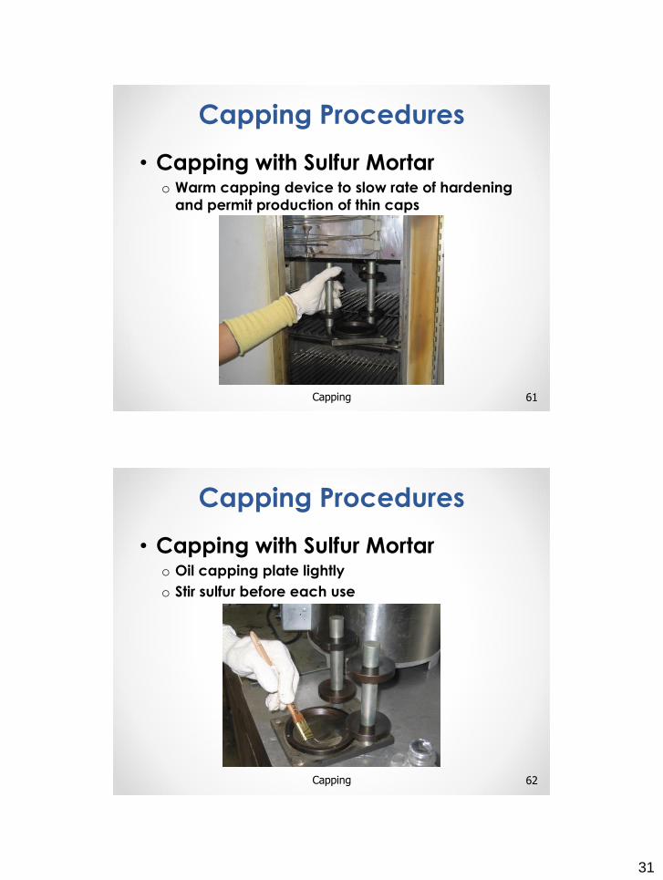
o Student retrial starts over at beginning of test
o Failure to pass any standard within the allowable
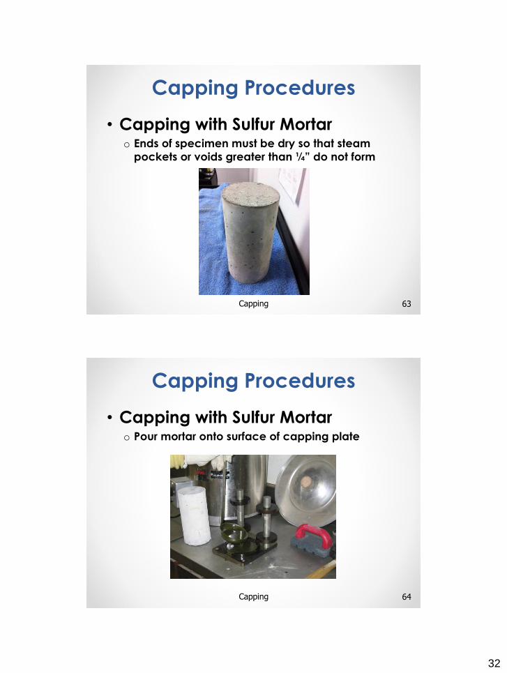
trials requires retaking of the entire performance
exam
6

4
ARDOT Standard Specifications
7ARDOT Standard Specifications
• 501.03 (Mix Design)o Minimum 28 day compressive strength: 4000 psi
o Test according to AASHTO T22 Compressive
Strength
8ARDOT Standard Specifications
Pavements
5
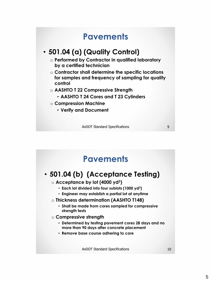
• 501.04 (a) (Quality Control)o Performed by Contractor in qualified laboratory
by a certified technician
o Contractor shall determine the specific locations
for samples and frequency of sampling for quality
control
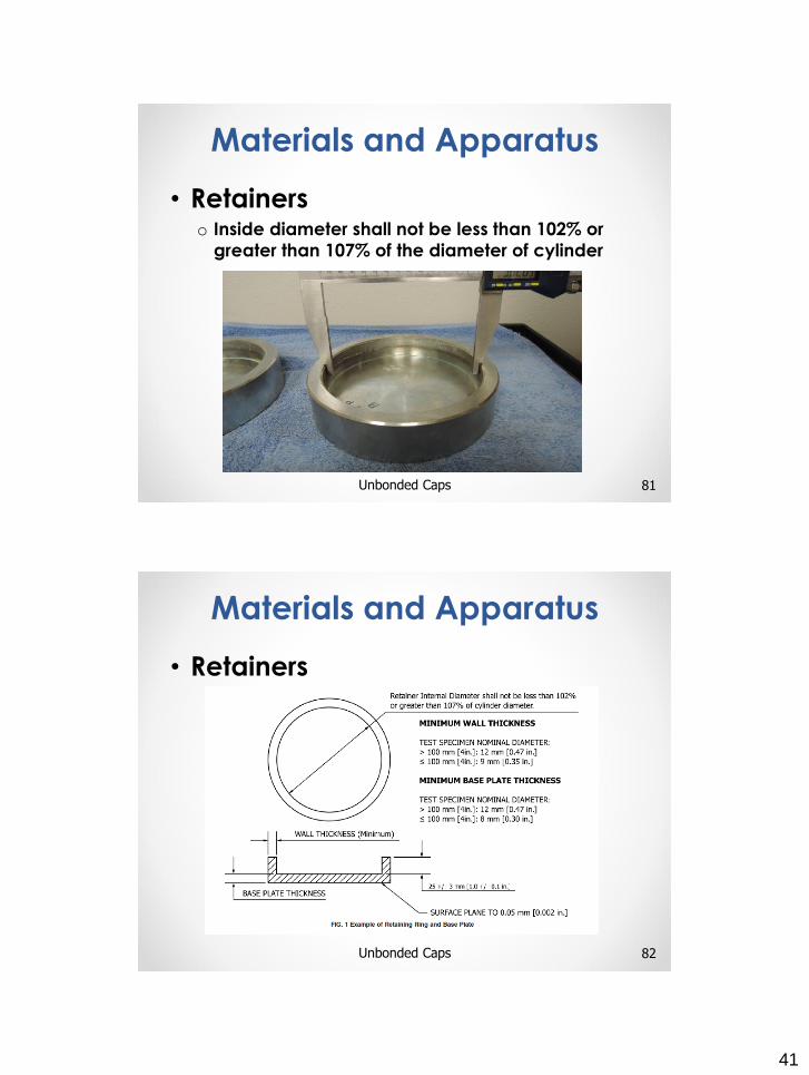
o AASHTO T 22 Compressive Strength
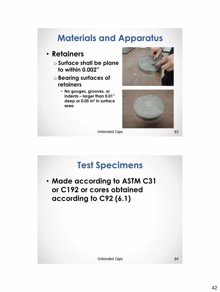
• AASHTO T 24 Cores and T 23 Cylinders
o Compression Machine
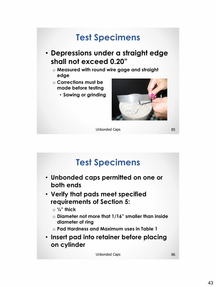
• Verify and Document
9ARDOT Standard Specifications
Pavements
• 501.04 (b) (Acceptance Testing)o Acceptance by lot (4000 yd3)
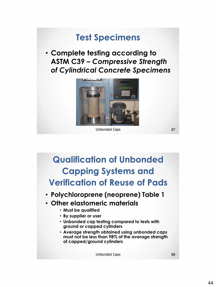
• Each lot divided into four sublots (1000 yd3)
• Engineer may establish a partial lot at anytime
o Thickness determination (AASHTO T148)
• Shall be made from cores sampled for compressive
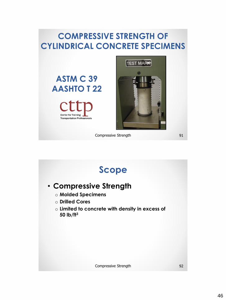
strength tests
o Compressive strength
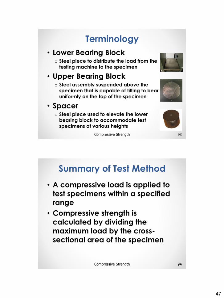
• Determined by testing pavement cores 28 days and no
more than 90 days after concrete placement
• Remove base course adhering to core
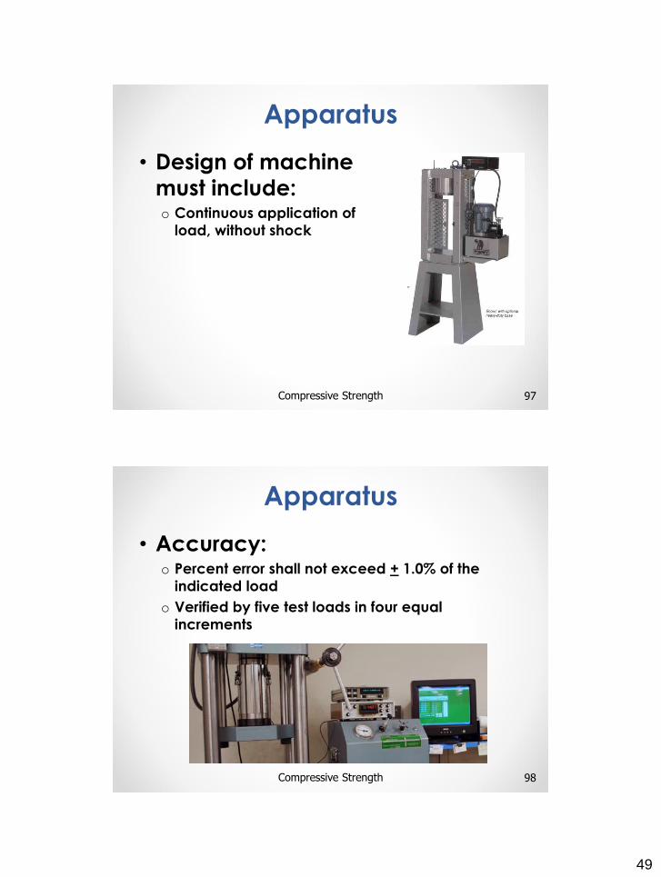
10ARDOT Standard Specifications
Pavements
6
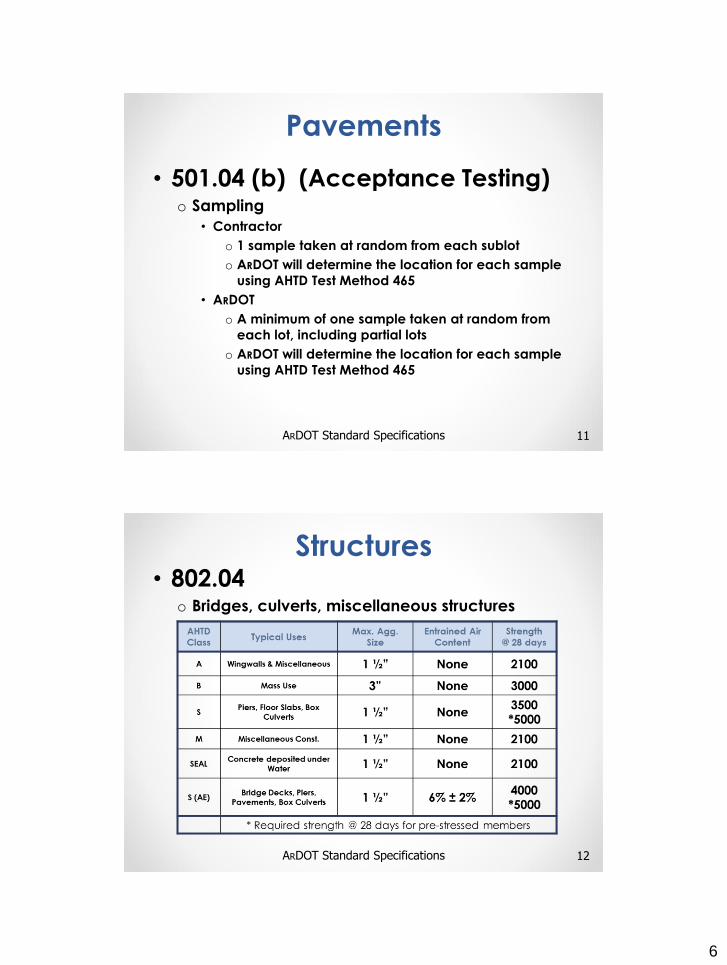
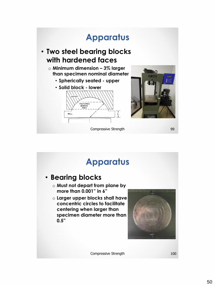
• 501.04 (b) (Acceptance Testing)o Sampling
• Contractor
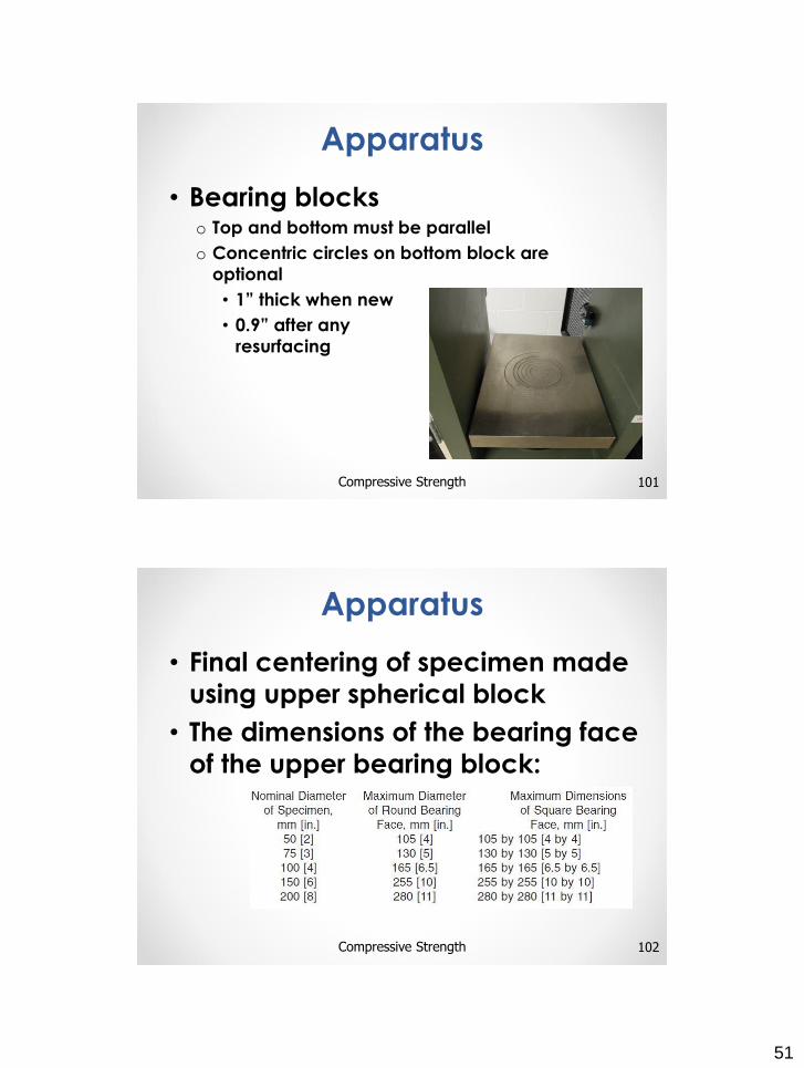
o 1 sample taken at random from each sublot
o ARDOT will determine the location for each sample
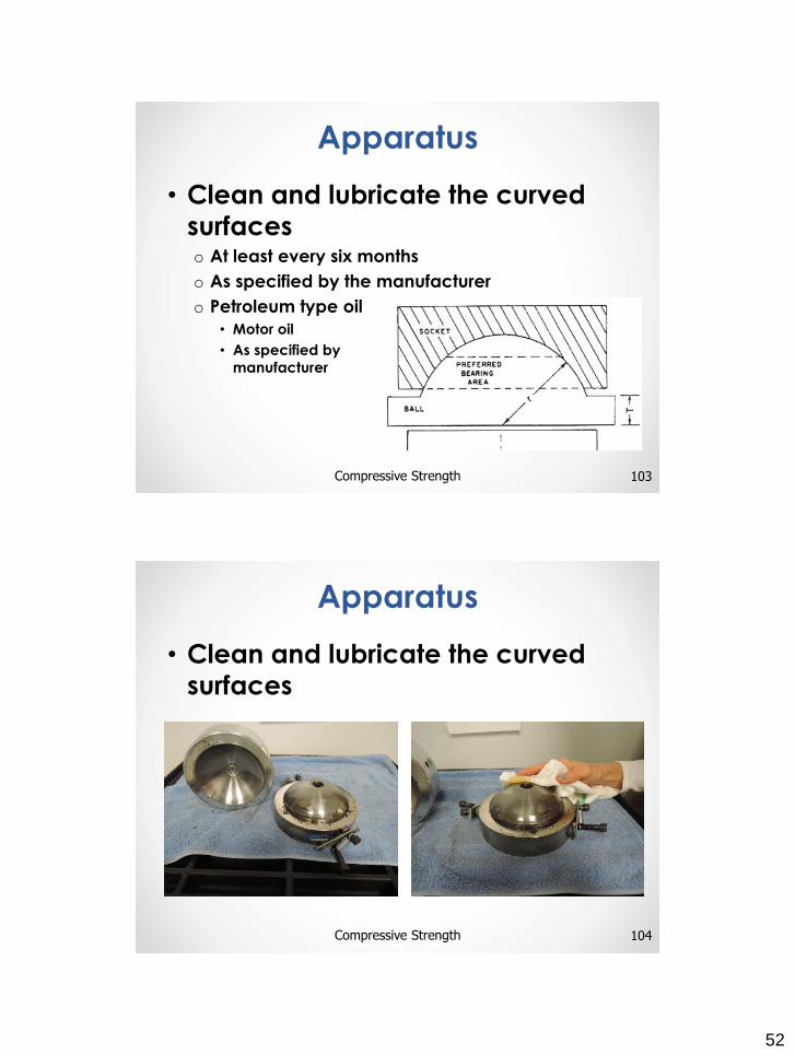
using AHTD Test Method 465
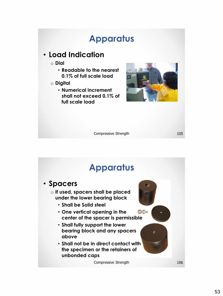
• ARDOT
o A minimum of one sample taken at random from
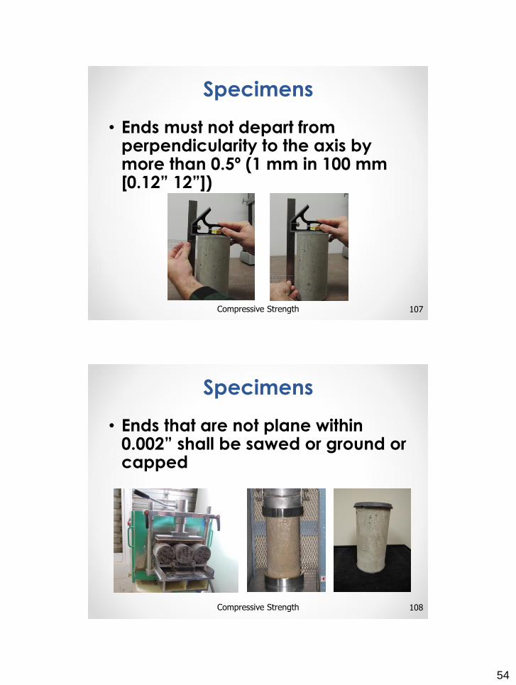
each lot, including partial lots
o ARDOT will determine the location for each sample
using AHTD Test Method 465
11ARDOT Standard Specifications
Pavements
• 802.04 o Bridges, culverts, miscellaneous structures
12ARDOT Standard Specifications
Structures
7
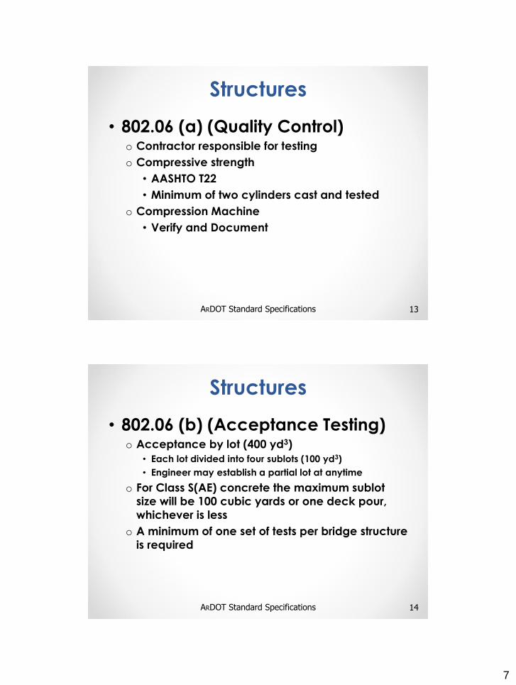
• 802.06 (a) (Quality Control) o Contractor responsible for testing
o Compressive strength
• AASHTO T22
• Minimum of two cylinders cast and tested
o Compression Machine
• Verify and Document
13ARDOT Standard Specifications
Structures
• 802.06 (b) (Acceptance Testing)o Acceptance by lot (400 yd3)
• Each lot divided into four sublots (100 yd3)
• Engineer may establish a partial lot at anytime
o For Class S(AE) concrete the maximum sublot
size will be 100 cubic yards or one deck pour,
whichever is less
o A minimum of one set of tests per bridge structure
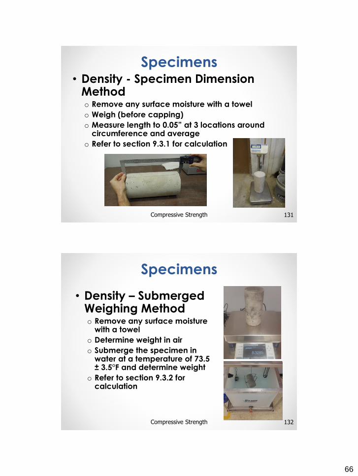
is required
14ARDOT Standard Specifications
Structures
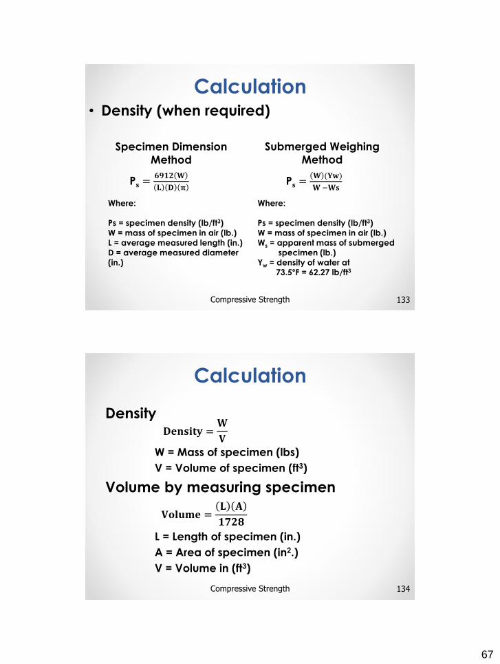
8
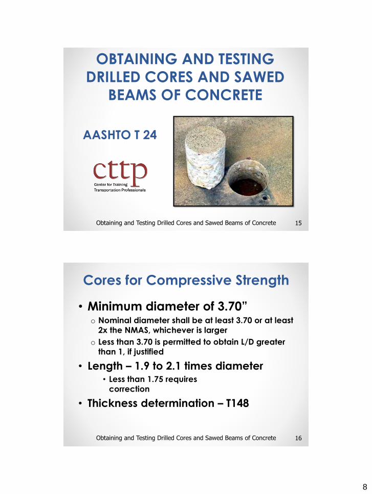
AASHTO T 24
15Obtaining and Testing Drilled Cores and Sawed Beams of Concrete
OBTAINING AND TESTING
DRILLED CORES AND SAWED
BEAMS OF CONCRETE
• Minimum diameter of 3.70”o Nominal diameter shall be at least 3.70 or at least
2x the NMAS, whichever is larger
o Less than 3.70 is permitted to obtain L/D greater
than 1, if justified
• Length – 1.9 to 2.1 times diameter• Less than 1.75 requires
correction
• Thickness determination – T148
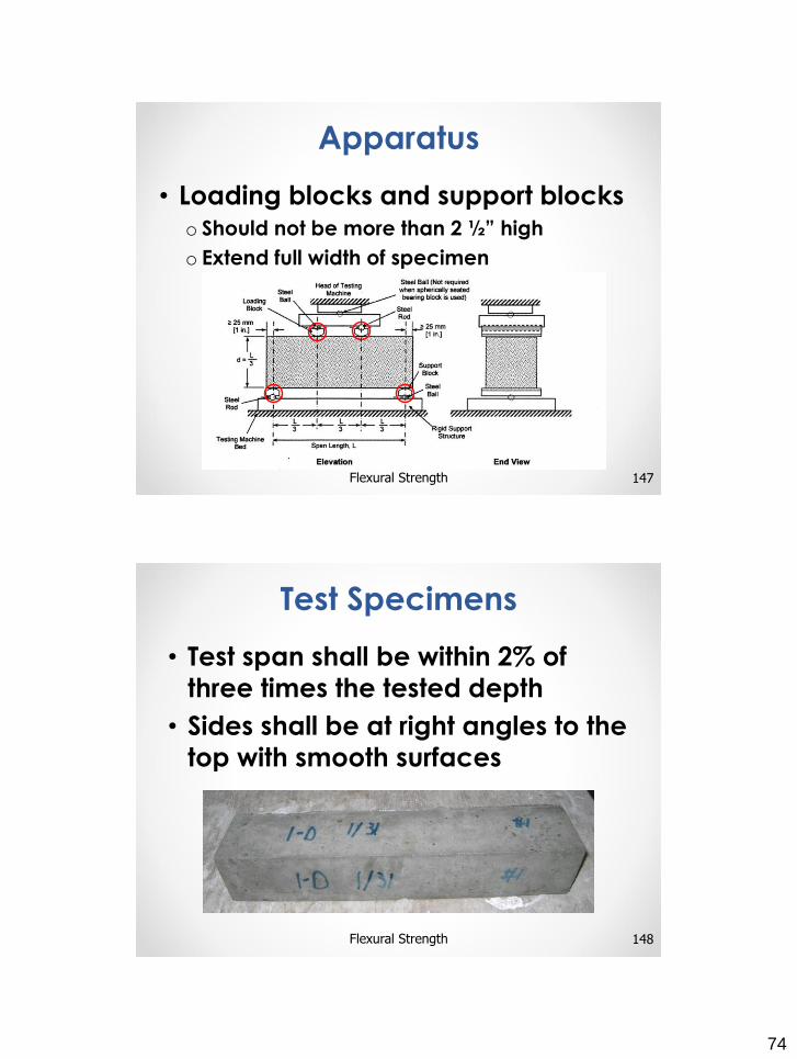
16Obtaining and Testing Drilled Cores and Sawed Beams of Concrete
Cores for Compressive Strength
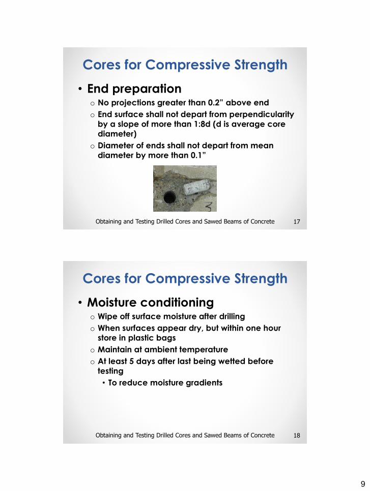
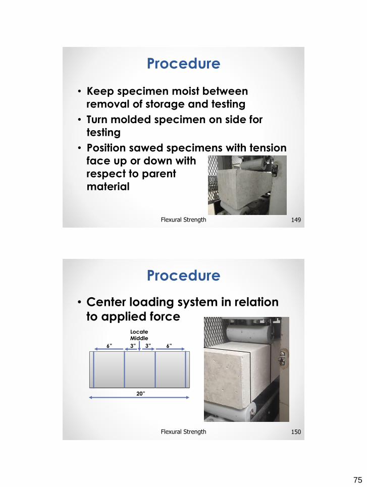
9
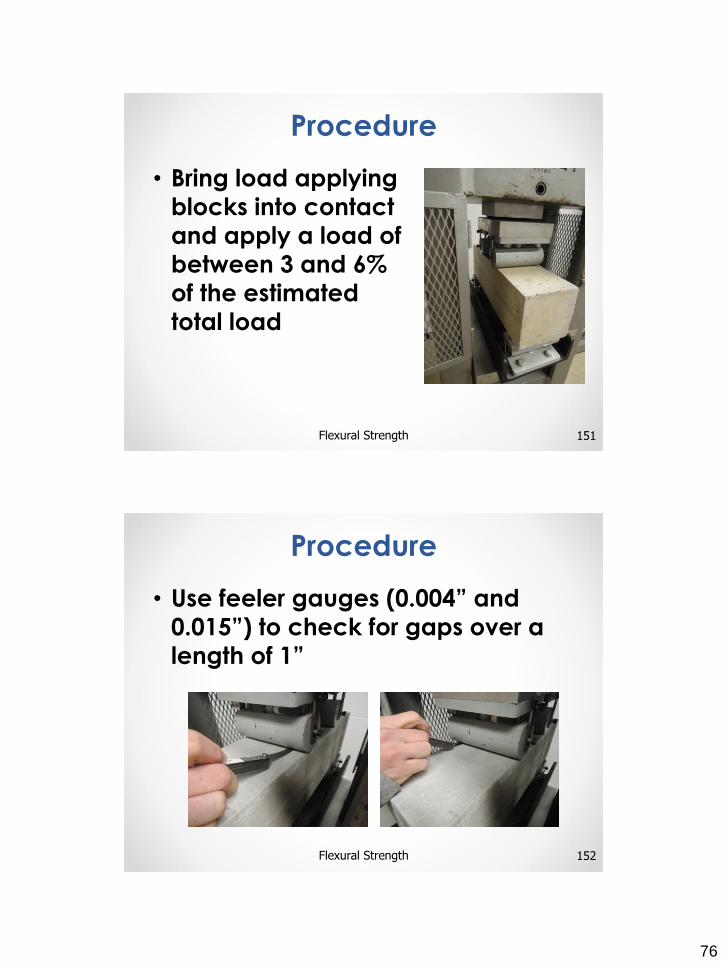
• End preparationo No projections greater than 0.2” above end
o End surface shall not depart from perpendicularity
by a slope of more than 1:8d (d is average core
diameter)
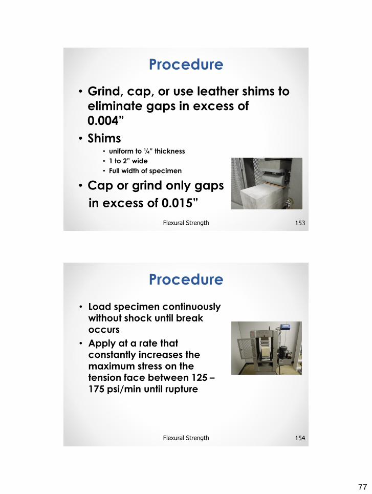
o Diameter of ends shall not depart from mean
diameter by more than 0.1”
17Obtaining and Testing Drilled Cores and Sawed Beams of Concrete
Cores for Compressive Strength
• Moisture conditioningo Wipe off surface moisture after drilling
o When surfaces appear dry, but within one hour
store in plastic bags
o Maintain at ambient temperature
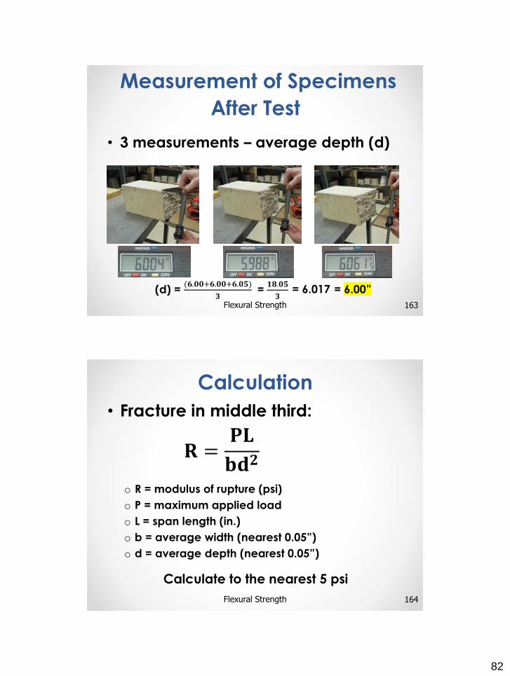
o At least 5 days after last being wetted before
testing
• To reduce moisture gradients
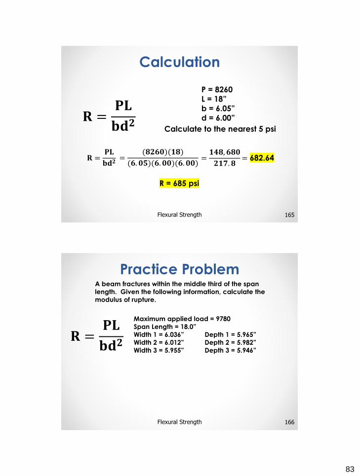
18Obtaining and Testing Drilled Cores and Sawed Beams of Concrete
Cores for Compressive Strength
10
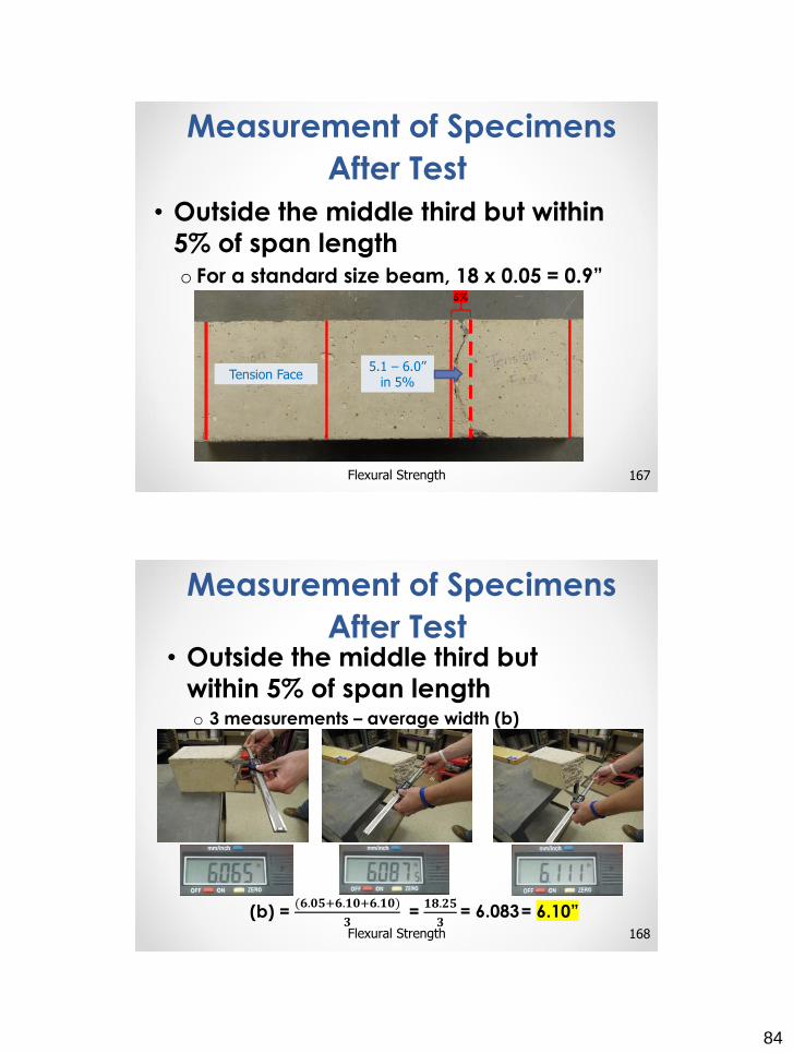
• Measure length for L/D ratio
• Measure two diameterso Do not test if largest and smallest diameter
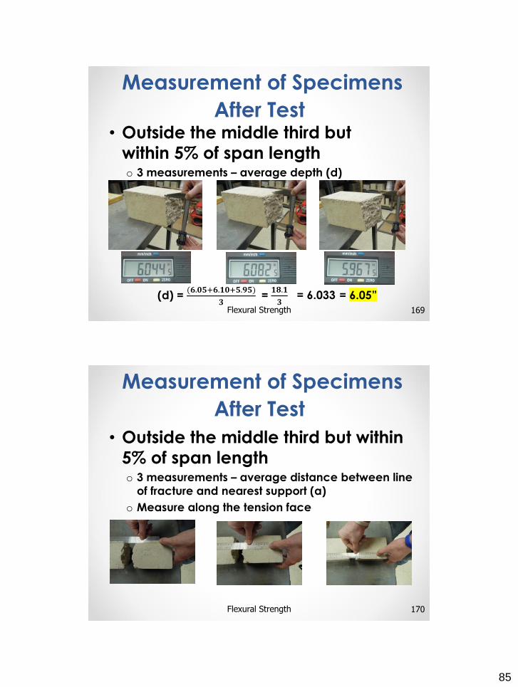
exceed 5 percent of average
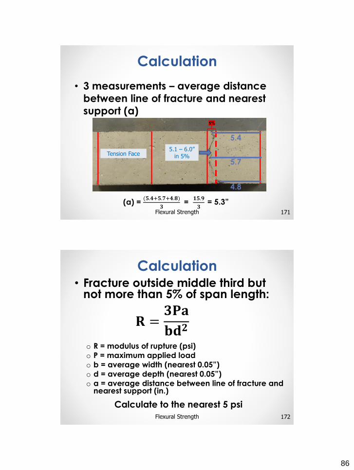
• Test within 7 days, unless specified
otherwise
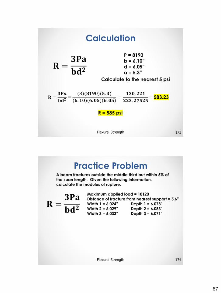
• Test according to T 22
• Report
19Obtaining and Testing Drilled Cores and Sawed Beams of Concrete
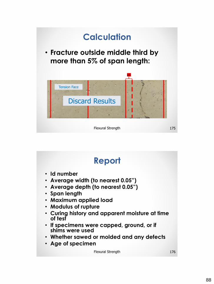
Cores for Compressive Strength
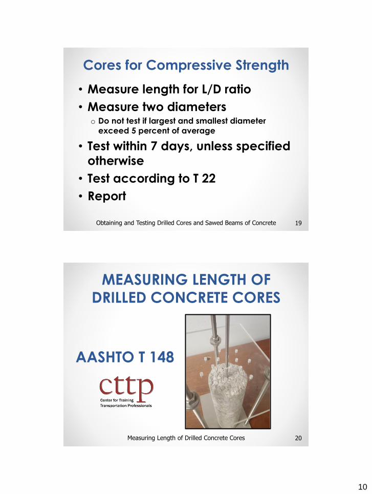
MEASURING LENGTH OF
DRILLED CONCRETE CORES
20
AASHTO T 148
Measuring Length of Drilled Concrete Cores
11
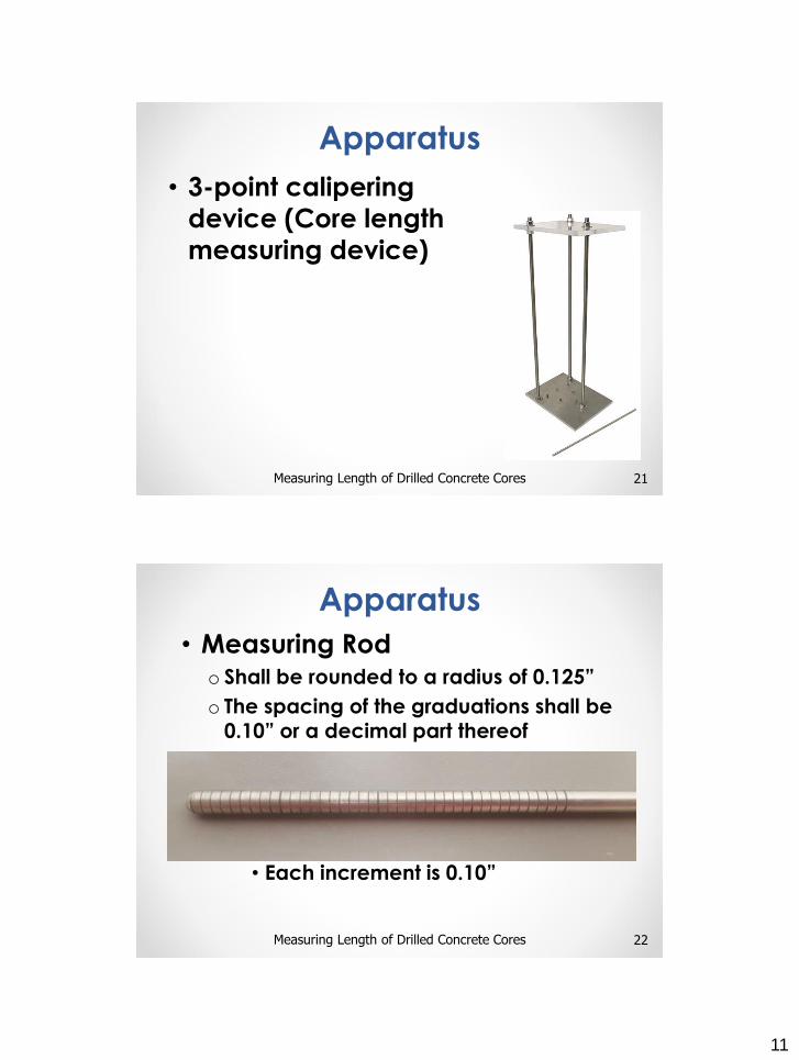
• 3-point calipering
device (Core length
measuring device)
21Measuring Length of Drilled Concrete Cores
Apparatus
• Measuring Rodo Shall be rounded to a radius of 0.125”
o The spacing of the graduations shall be 0.10” or a decimal part thereof
• Each increment is 0.10”
22Measuring Length of Drilled Concrete Cores
Apparatus
12
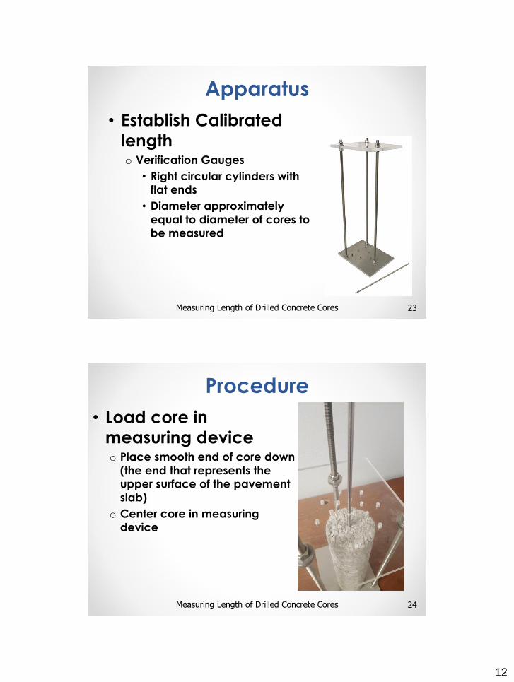
• Establish Calibrated
lengtho Verification Gauges
• Right circular cylinders with
flat ends
• Diameter approximately
equal to diameter of cores to
be measured
23Measuring Length of Drilled Concrete Cores
Apparatus
• Load core in
measuring deviceo Place smooth end of core down
(the end that represents the
upper surface of the pavement
slab)
o Center core in measuring
device
24Measuring Length of Drilled Concrete Cores
Procedure
13
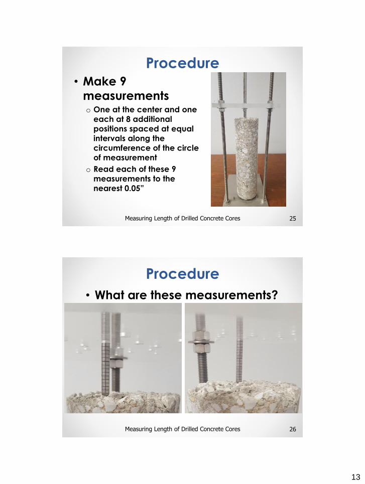
• Make 9
measurementso One at the center and one
each at 8 additional
positions spaced at equal
intervals along the
circumference of the circle
of measurement
o Read each of these 9
measurements to the
nearest 0.05”
25Measuring Length of Drilled Concrete Cores
Procedure
• What are these measurements?
26Measuring Length of Drilled Concrete Cores
Procedure
14
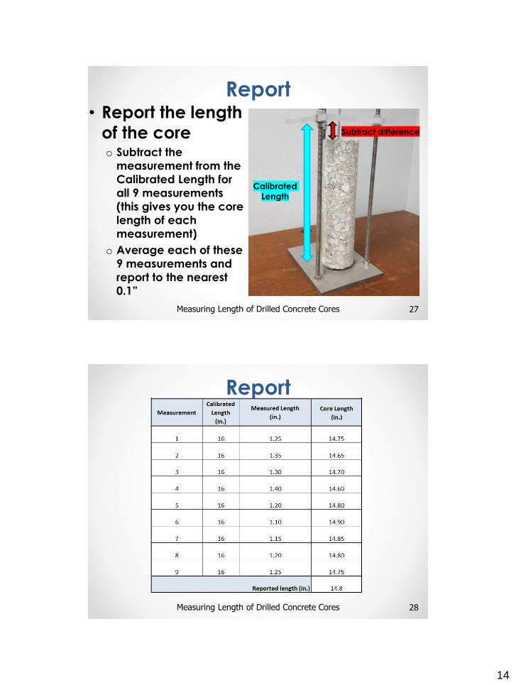
• Report the length
of the coreo Subtract the
measurement from the
Calibrated Length for
all 9 measurements
(this gives you the core
length of each
measurement)
o Average each of these
9 measurements and
report to the nearest
0.1”
27Measuring Length of Drilled Concrete Cores
Report
Subtract difference
Calibrated
Length
Example
28Measuring Length of Drilled Concrete Cores
Report
15
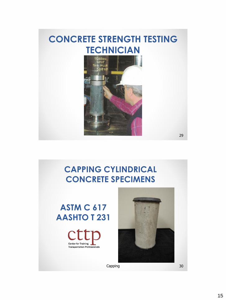
CONCRETE STRENGTH TESTING
TECHNICIAN
29
CAPPING CYLINDRICAL
CONCRETE SPECIMENS
30
ASTM C 617
AASHTO T 231
Capping
16
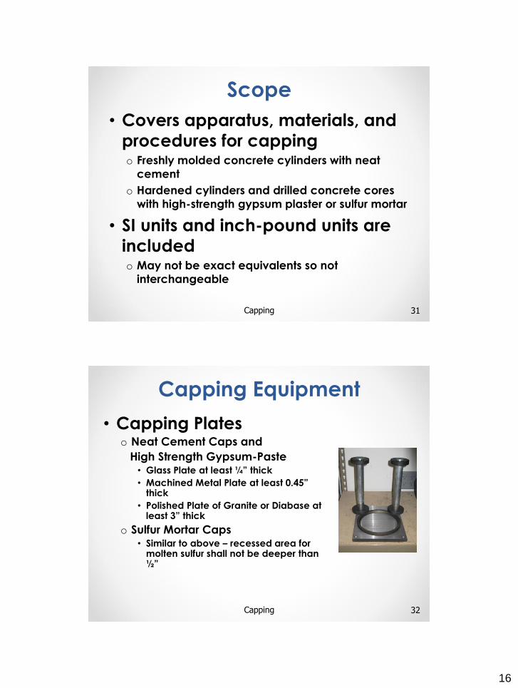
Scope
• Covers apparatus, materials, and
procedures for capping o Freshly molded concrete cylinders with neat
cement
o Hardened cylinders and drilled concrete cores
with high-strength gypsum plaster or sulfur mortar
• SI units and inch-pound units are
includedo May not be exact equivalents so not
interchangeable
31Capping
• Capping Plateso Neat Cement Caps and
High Strength Gypsum-Paste• Glass Plate at least ¼” thick
• Machined Metal Plate at least 0.45” thick
• Polished Plate of Granite or Diabase at least 3” thick
o Sulfur Mortar Caps• Similar to above – recessed area for
molten sulfur shall not be deeper than ½”
32Capping
Capping Equipment
17
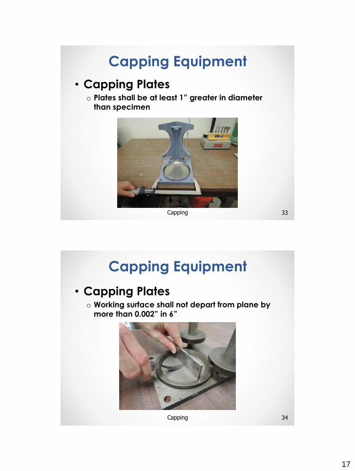
• Capping Plateso Plates shall be at least 1” greater in diameter
than specimen
33Capping
Capping Equipment
• Capping Plateso Working surface shall not depart from plane by
more than 0.002” in 6”
34Capping
Capping Equipment
18
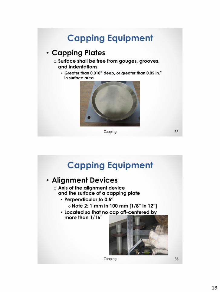
• Capping Plateso Surface shall be free from gouges, grooves,
and indentations
• Greater than 0.010” deep, or greater than 0.05 in.2
in surface area
35Capping
Capping Equipment
• Alignment Deviceso Axis of the alignment device
and the surface of a capping plate
• Perpendicular to 0.5°
oNote 2: 1 mm in 100 mm [1/8” in 12”]
• Located so that no cap off-centered by more than 1/16”
36Capping
Capping Equipment
19
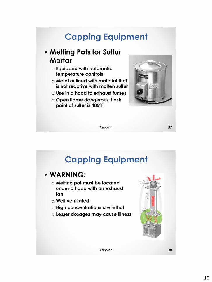
• Melting Pots for Sulfur
Mortaro Equipped with automatic
temperature controls
o Metal or lined with material that
is not reactive with molten sulfur
o Use in a hood to exhaust fumes
o Open flame dangerous: flash
point of sulfur is 405°F
37Capping
Capping Equipment
• WARNING:o Melting pot must be located
under a hood with an exhaust
fan
o Well ventilated
o High concentrations are lethal
o Lesser dosages may cause illness
38Capping
Capping Equipment
20
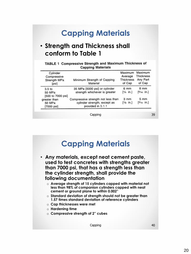
• Strength and Thickness shall
conform to Table 1
39Capping
Capping Materials
• Any materials, except neat cement paste, used to test concretes with strengths greater than 7000 psi, that has a strength less than the cylinder strength, shall provide the following documentationo Average strength of 15 cylinders capped with material not
less than 98% of companion cylinders capped with neat cement or ground plane to within 0.002”
o Standard deviation of strength should not be greater than 1.57 times standard deviation of reference cylinders
o Cap thicknesses were met
o Hardening time
o Compressive strength of 2” cubes
40Capping
Capping Materials
21
• Compressive strength of
capping materials shall be
determined using 2” cubes
(ASTM C109/AASHTO T106)o Cure same as material capping
cylinders
• Strength determined on receipt
of new lot and at intervals not
to exceed three months
41Capping
Capping Materials
• Neat Hydraulic Cement Pasteo Make qualification tests on 2” cubes
• To determine effect of w/c ratio and age
o Mix to desired consistency generally 2 to 4 hours
before paste is to be used
42Capping
Capping Materials
22
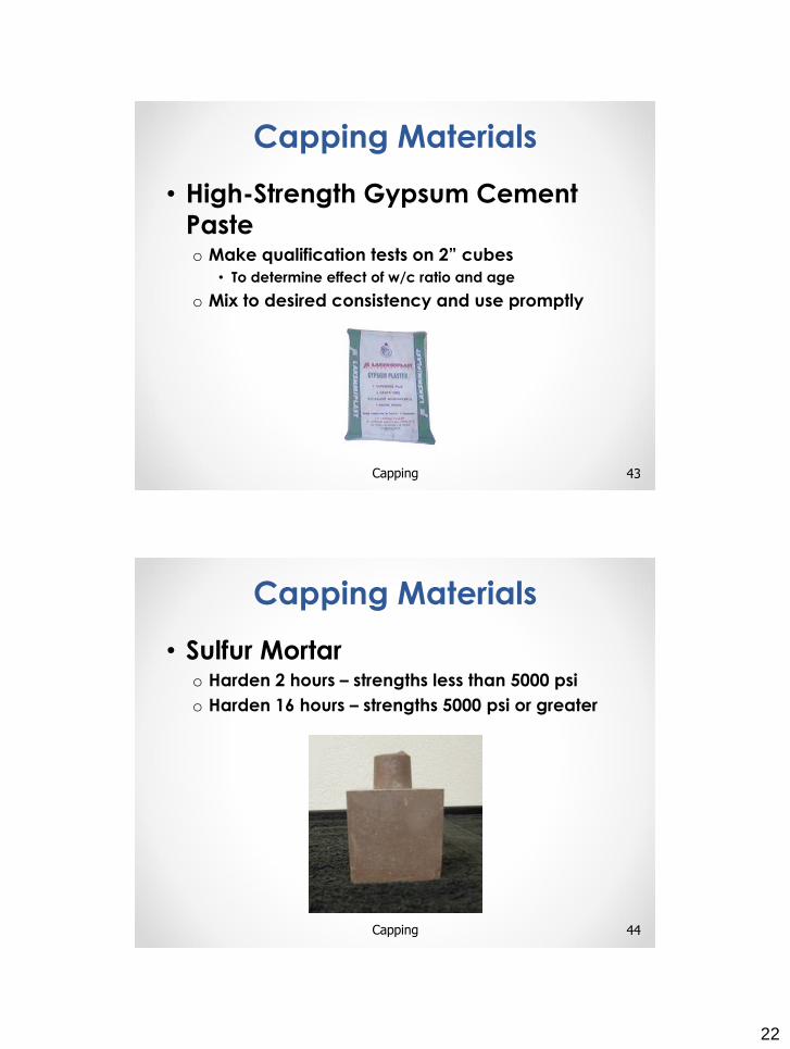
• High-Strength Gypsum Cement
Pasteo Make qualification tests on 2” cubes
• To determine effect of w/c ratio and age
o Mix to desired consistency and use promptly
43Capping
Capping Materials
• Sulfur Mortaro Harden 2 hours – strengths less than 5000 psi
o Harden 16 hours – strengths 5000 psi or greater
44Capping
Capping Materials
23
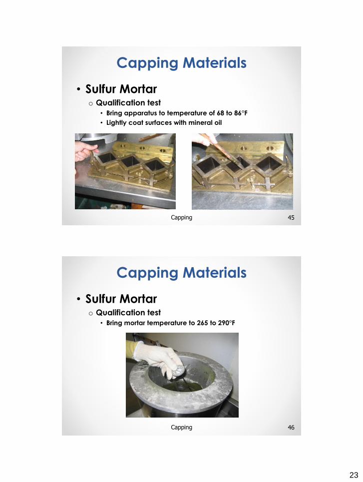
• Sulfur Mortar o Qualification test
• Bring apparatus to temperature of 68 to 86°F
• Lightly coat surfaces with mineral oil
45Capping
Capping Materials
• Sulfur Mortaro Qualification test
• Bring mortar temperature to 265 to 290°F
46Capping
Capping Materials
24
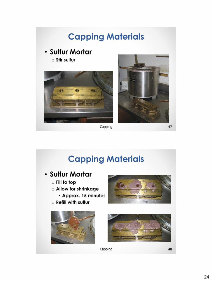
• Sulfur Mortaro Stir sulfur
47Capping
Capping Materials
• Sulfur Mortaro Fill to top
o Allow for shrinkage
• Approx. 15 minutes
o Refill with sulfur
48Capping
Capping Materials
25
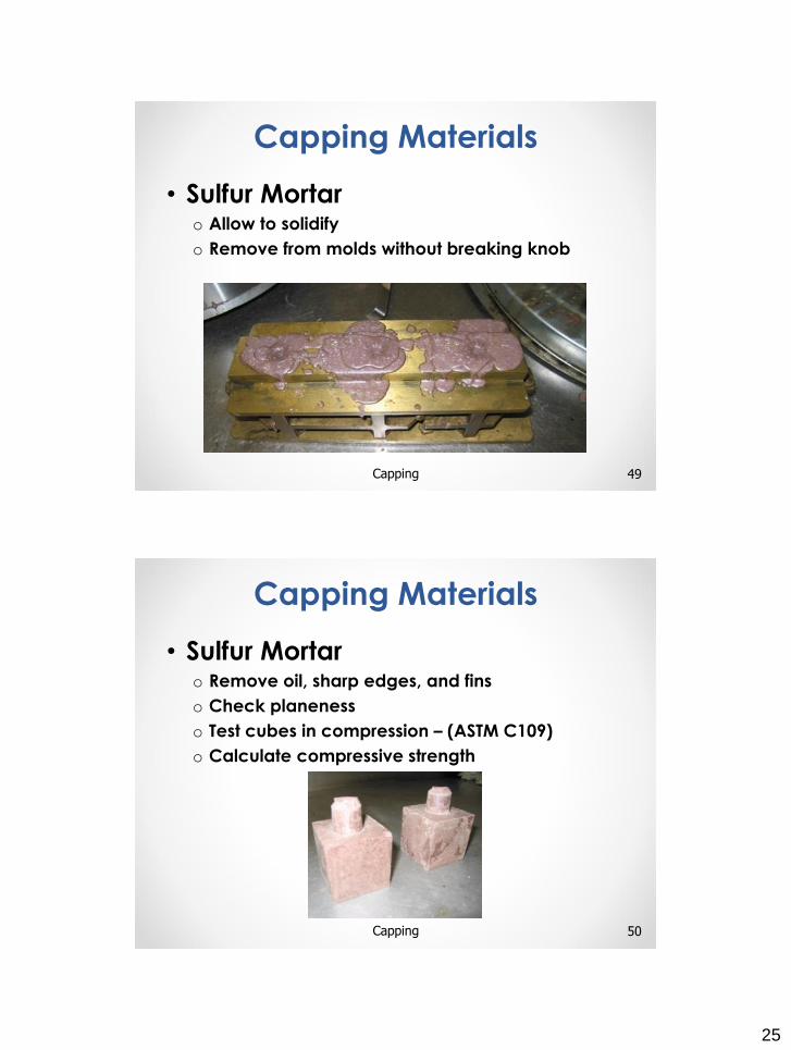
• Sulfur Mortaro Allow to solidify
o Remove from molds without breaking knob
49Capping
Capping Materials
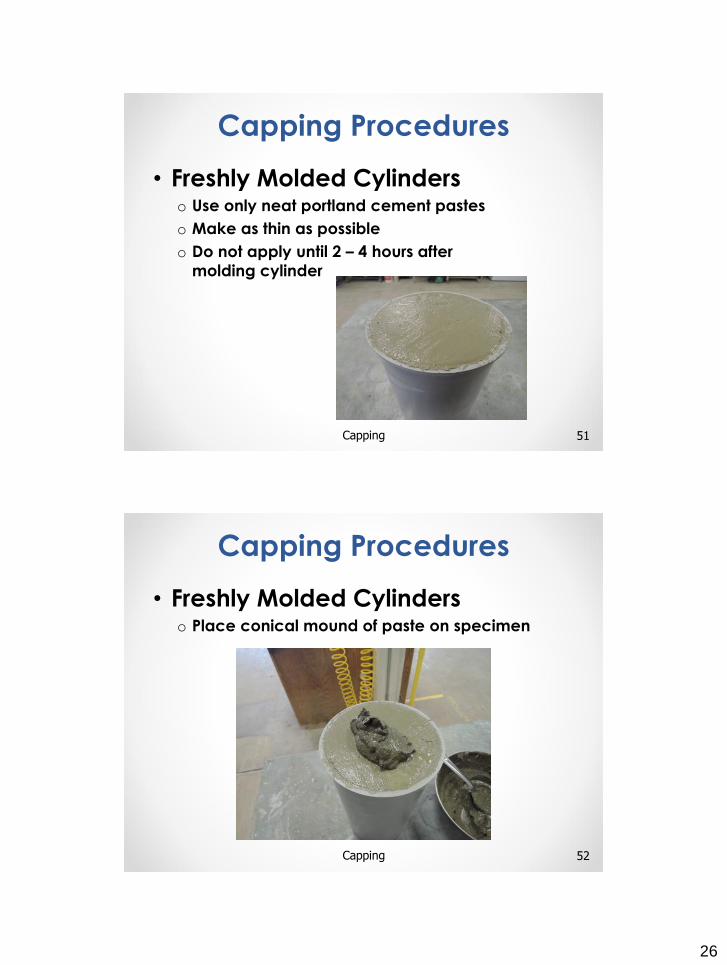
• Sulfur Mortaro Remove oil, sharp edges, and fins
o Check planeness
o Test cubes in compression – (ASTM C109)
o Calculate compressive strength
50Capping
Capping Materials
26
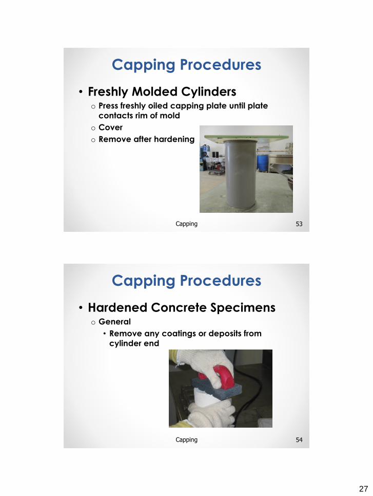
• Freshly Molded Cylinderso Use only neat portland cement pastes
o Make as thin as possible
o Do not apply until 2 – 4 hours after
molding cylinder
51Capping
Capping Procedures
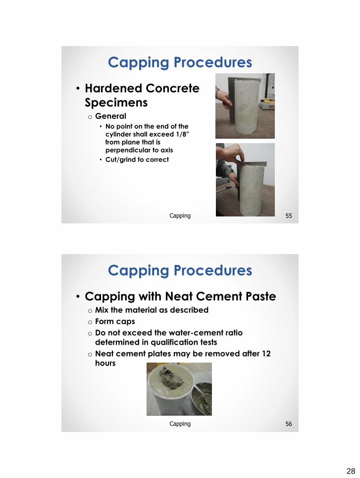
• Freshly Molded Cylinderso Place conical mound of paste on specimen
52Capping
Capping Procedures
27
• Freshly Molded Cylinderso Press freshly oiled capping plate until plate
contacts rim of mold
o Cover
o Remove after hardening
53Capping
Capping Procedures
• Hardened Concrete Specimenso General
• Remove any coatings or deposits from
cylinder end
54Capping
Capping Procedures
28
• Hardened Concrete
Specimenso General
• No point on the end of the
cylinder shall exceed 1/8”
from plane that is
perpendicular to axis
• Cut/grind to correct
55Capping
Capping Procedures
• Capping with Neat Cement Pasteo Mix the material as described
o Form caps
o Do not exceed the water-cement ratio
determined in qualification tests
o Neat cement plates may be removed after 12
hours
56Capping
Capping Procedures
29
• Capping with High-Strength
Gypsum Pasteo Mix the material as described
o Do not exceed the water-cement ratio
determined in qualification tests
57Capping
Capping Procedures
• Capping with High-Strength
Gypsum Pasteo Form the caps
58Capping
Capping Procedures
30
• Capping with High-Strength
Gypsum Pasteo Generally, capping plates may be removed
within 45 minutes
59Capping
Capping Procedures
• Capping with Sulfur Mortaro Heat sulfur between 265
to 290°F
o Check temperature
hourly
o Five use limit
o No reuse for concrete
compressive strength
greater than 5000 psi
60Capping
Capping Procedures
31
• Capping with Sulfur Mortaro Warm capping device to slow rate of hardening
and permit production of thin caps
61Capping
Capping Procedures
• Capping with Sulfur Mortaro Oil capping plate lightly
o Stir sulfur before each use
62Capping
Capping Procedures
32
• Capping with Sulfur Mortaro Ends of specimen must be dry so that steam
pockets or voids greater than ¼” do not form
63Capping
Capping Procedures
• Capping with Sulfur Mortaro Pour mortar onto surface of capping plate
64Capping
Capping Procedures
33
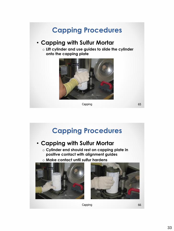
• Capping with Sulfur Mortaro Lift cylinder and use guides to slide the cylinder
onto the capping plate
65Capping
Capping Procedures
• Capping with Sulfur Mortaro Cylinder end should rest on capping plate in
positive contact with alignment guides
o Make contact until sulfur hardens
66Capping
Capping Procedures
34
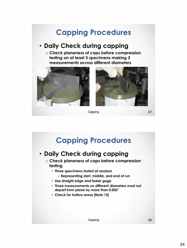
• Daily Check during cappingo Check planeness of caps before compression
testing on at least 3 specimens making 3
measurements across different diameters
67Capping
Capping Procedures
• Daily Check during capping o Check planeness of caps before compression
testing
• Three specimens tested at random
o Representing start, middle, and end of run
• Use straight edge and feeler gage
• Three measurements on different diameters must not
depart from plane by more than 0.002”
• Check for hollow areas [Note 15]
68Capping
Capping Procedures
35
• Daily Check during compression
testingo Thickness of caps on at least three specimens
• Recover at least six pieces of capping material
• Measure thickness to the nearest 0.01”
• Compare averages and maximum thickness to values
in Table 1
69Capping
Capping Procedures
• Maintain moist cured specimens in moist
condition
• Do not store specimens with gypsum
plaster caps immersed in water or for
more than 4 hours in moist room
• Protect gypsum caps from dripping water
• Do not test until strength has developed
in capping material
70Capping
Protection of Specimens
After Capping
36
UNBONDED CAPS FOR
CONCRETE CYLINDERS
71
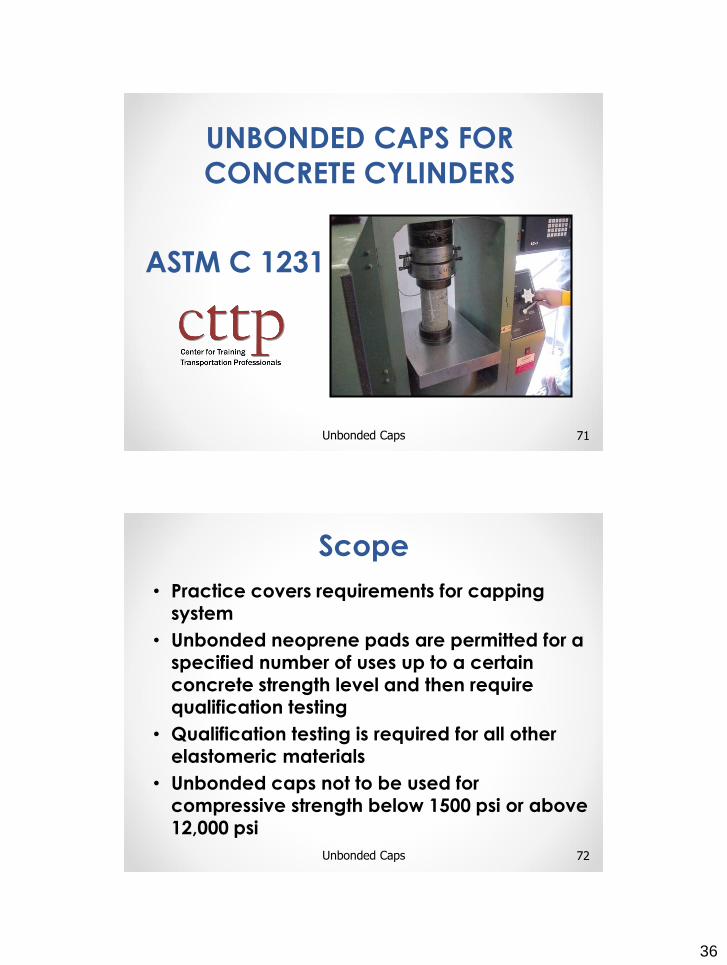
ASTM C 1231
Unbonded Caps
• Practice covers requirements for capping system
• Unbonded neoprene pads are permitted for a specified number of uses up to a certain concrete strength level and then require qualification testing
• Qualification testing is required for all other elastomeric materials
• Unbonded caps not to be used for compressive strength below 1500 psi or above 12,000 psi
72
Scope
Unbonded Caps
37
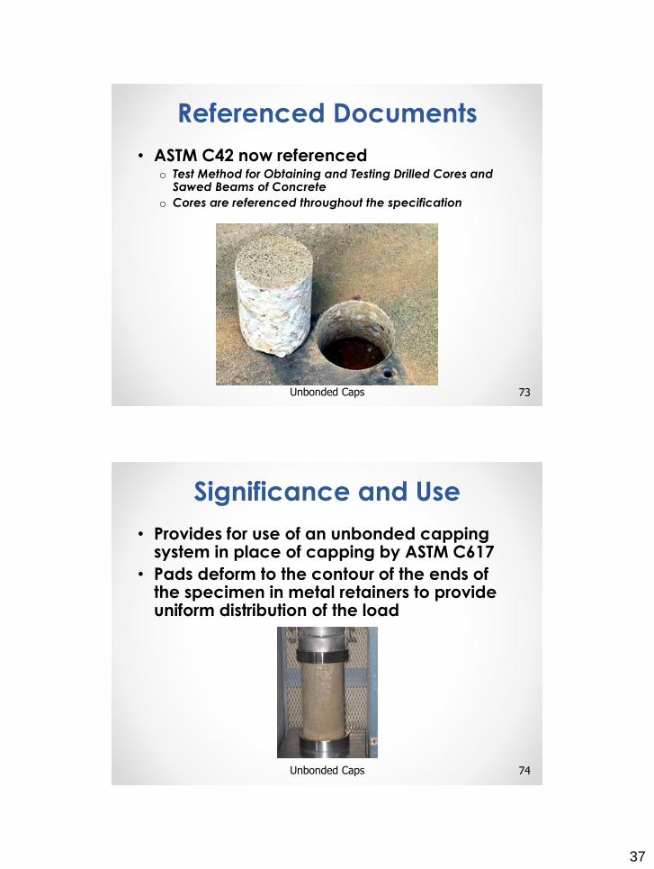
• ASTM C42 now referencedo Test Method for Obtaining and Testing Drilled Cores and
Sawed Beams of Concrete
o Cores are referenced throughout the specification
73
Referenced Documents
Unbonded Caps
• Provides for use of an unbonded capping system in place of capping by ASTM C617
• Pads deform to the contour of the ends of the specimen in metal retainers to provide uniform distribution of the load
74Unbonded Caps
Significance and Use
38
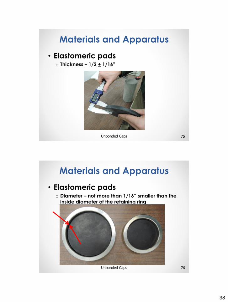
• Elastomeric padso Thickness – 1/2 + 1/16”
75Unbonded Caps
Materials and Apparatus
• Elastomeric padso Diameter – not more than 1/16” smaller than the
inside diameter of the retaining ring
76Unbonded Caps
Materials and Apparatus
39
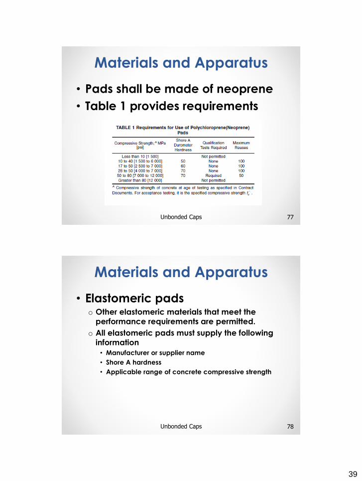
• Pads shall be made of neoprene
• Table 1 provides requirements
77Unbonded Caps
Materials and Apparatus
• Elastomeric padso Other elastomeric materials that meet the
performance requirements are permitted.
o All elastomeric pads must supply the following
information
• Manufacturer or supplier name
• Shore A hardness
• Applicable range of concrete compressive strength
78Unbonded Caps
Materials and Apparatus
40
• Elastomeric padso User shall maintain record indicating
• Date pads are put in service
• Pad Durometer
• Number of uses
79Unbonded Caps
Materials and Apparatus
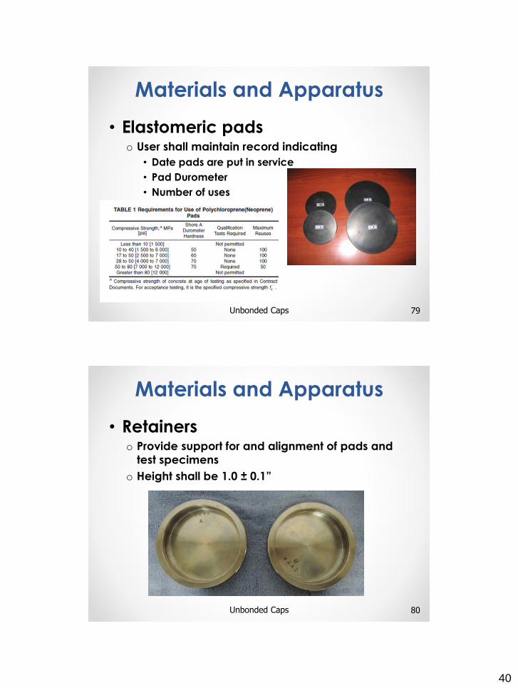
• Retainerso Provide support for and alignment of pads and
test specimens
o Height shall be 1.0 ± 0.1”
80Unbonded Caps
Materials and Apparatus
41
• Retainerso Inside diameter shall not be less than 102% or
greater than 107% of the diameter of cylinder
81Unbonded Caps
Materials and Apparatus
• Retainers
82Unbonded Caps
Materials and Apparatus
42
• Retainerso Surface shall be plane
to within 0.002”
o Bearing surfaces of retainers• No gouges, grooves, or
indents – larger than 0.01”
deep or 0.05 in2 in surface
area
83Unbonded Caps
Materials and Apparatus
• Made according to ASTM C31
or C192 or cores obtained
according to C92 (6.1)
84Unbonded Caps
Test Specimens
43
• Depressions under a straight edge
shall not exceed 0.20”o Measured with round wire gage and straight
edge
o Corrections must be
made before testing
• Sawing or grinding
85Unbonded Caps
Test Specimens
• Unbonded caps permitted on one or
both ends
• Verify that pads meet specified
requirements of Section 5:o ½” thick
o Diameter not more that 1/16” smaller than inside
diameter of ring
o Pad Hardness and Maximum uses in Table 1
• Insert pad into retainer before placing
on cylinder
86Unbonded Caps
Test Specimens
44
• Complete testing according to
ASTM C39 – Compressive Strength
of Cylindrical Concrete Specimens
87Unbonded Caps
Test Specimens
• Polychloroprene (neoprene) Table 1
• Other elastomeric materials• Must be qualified
• By supplier or user
• Unbonded cap testing compared to tests with ground or capped cylinders
• Average strength obtained using unbonded caps must not be less than 98% of the average strength of capped/ground cylinders
88Unbonded Caps
Qualification of Unbonded
Capping Systems and
Verification of Reuse of Pads
45
• Establishing reuseso Additional uses to Table 1
o Only tests that are within 2000 psi of highest
strength level can be included
o Records must be maintained
89Unbonded Caps
Qualification of Unbonded
Capping Systems and
Verification of Reuse of Pads
• Qualification and pad reuse testingo Pairs of cylinders cured alike
o Test one by grinding or capping and one by unbonded capping
o 10 pairs at both highest and lowest strength levels
o Minimum of two samples made on different days
90Unbonded Caps
Qualification of Unbonded
Capping Systems and
Verification of Reuse of Pads
46
COMPRESSIVE STRENGTH OF
CYLINDRICAL CONCRETE SPECIMENS
91
ASTM C 39
AASHTO T 22
Compressive Strength
• Compressive Strengtho Molded Specimens
o Drilled Cores
o Limited to concrete with density in excess of
50 lb/ft3
92
Scope
Compressive Strength
47
• Lower Bearing Blocko Steel piece to distribute the load from the
testing machine to the specimen
• Upper Bearing Blocko Steel assembly suspended above the
specimen that is capable of tilting to bear
uniformly on the top of the specimen
• Spacero Steel piece used to elevate the lower
bearing block to accommodate test
specimens at various heights
93
Terminology
Compressive Strength
• A compressive load is applied to
test specimens within a specified
range
• Compressive strength is
calculated by dividing the
maximum load by the cross-
sectional area of the specimen
94Compressive Strength
Summary of Test Method
48
• Care must be used in interpretation of the results:o Size
o Shape
o Batching
o Mixing Procedures
o Sampling
o Molding
o Fabrication
o Age, Temperature, and Moisture Conditions during curing
95Compressive Strength
Significance and Use
• Testing Machineo Sufficient Capacity
o Capability to provide rates of loading in section 7.5
o Verification in accordance with Practice E4• Within 13 months of last calibration
• Original installation or relocation
• After repairs or adjustments
• Reason to doubt accuracy
96Compressive Strength
Apparatus
49
• Design of machine
must include:o Continuous application of
load, without shock
97Compressive Strength
Apparatus
• Accuracy:o Percent error shall not exceed + 1.0% of the
indicated load
o Verified by five test loads in four equal
increments
98Compressive Strength
Apparatus
50
• Two steel bearing blocks
with hardened faceso Minimum dimension – 3% larger
than specimen nominal diameter
• Spherically seated - upper
• Solid block - lower
99Compressive Strength
Apparatus
• Bearing blockso Must not depart from plane by
more than 0.001” in 6”
o Larger upper blocks shall have
concentric circles to facilitate
centering when larger than
specimen diameter more than
0.5”
100Compressive Strength
Apparatus
51
• Bearing blockso Top and bottom must be parallel
o Concentric circles on bottom block are
optional
• 1” thick when new
• 0.9” after any
resurfacing
101Compressive Strength
Apparatus
• Final centering of specimen made
using upper spherical block
• The dimensions of the bearing face
of the upper bearing block:
102Compressive Strength
Apparatus
52
• Clean and lubricate the curved
surfaces o At least every six months
o As specified by the manufacturer
o Petroleum type oil
• Motor oil
• As specified by
manufacturer
103Compressive Strength
Apparatus
• Clean and lubricate the curved
surfaces
104Compressive Strength
Apparatus
53
• Load Indicationo Dial
• Readable to the nearest
0.1% of full scale load
o Digital
• Numerical increment
shall not exceed 0.1% of
full scale load
105Compressive Strength
Apparatus
• Spacerso If used, spacers shall be placed
under the lower bearing block
• Shall be Solid steel
• One vertical opening in the
center of the spacer is permissible
• Shall fully support the lower
bearing block and any spacers
above
• Shall not be in direct contact with
the specimen or the retainers of
unbonded caps
106Compressive Strength
Apparatus
54
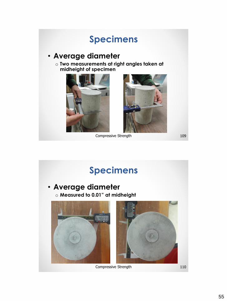
• Ends must not depart from perpendicularity to the axis by more than 0.5º (1 mm in 100 mm [0.12” 12”])
107Compressive Strength
Specimens
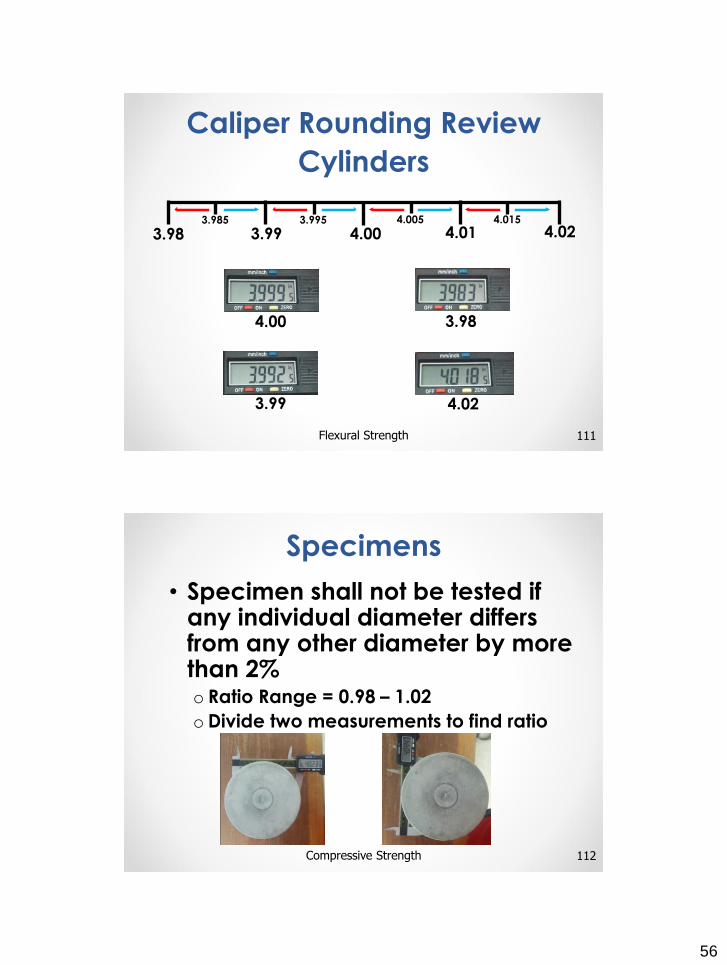
• Ends that are not plane within 0.002” shall be sawed or ground or capped
108Compressive Strength
Specimens
55
• Average diametero Two measurements at right angles taken at
midheight of specimen
109Compressive Strength
Specimens
• Average diametero Measured to 0.01” at midheight
110Compressive Strength
Specimens
56
111Flexural Strength
Caliper Rounding Review
Cylinders
4.00 3.98
3.99
3.98 3.99 4.00 4.01 4.023.985 3.995 4.005 4.015
4.02
• Specimen shall not be tested if any individual diameter differs from any other diameter by more than 2%o Ratio Range = 0.98 – 1.02
oDivide two measurements to find ratio
112Compressive Strength
Specimens

57
• Do the individual diameters differ from each other by more than 2%? Determine the average diameter.
Ratio
113Compressive Strength
Specimens
P
(𝟒.𝟎𝟐+𝟒.𝟎𝟒)
𝟐= = 4.03”
𝟖.𝟎𝟔
𝟐
𝟒.𝟎𝟐
𝟒.𝟎𝟒= .9950
Average Diameter
Range = 0.98 – 1.02
Diameter 1 = 3.96”
Diameter 2 = 4.06”
114Compressive Strength
Practice Problem
• Do the individual diameters differ from each other by more than 2%? Determine the average diameter.
58
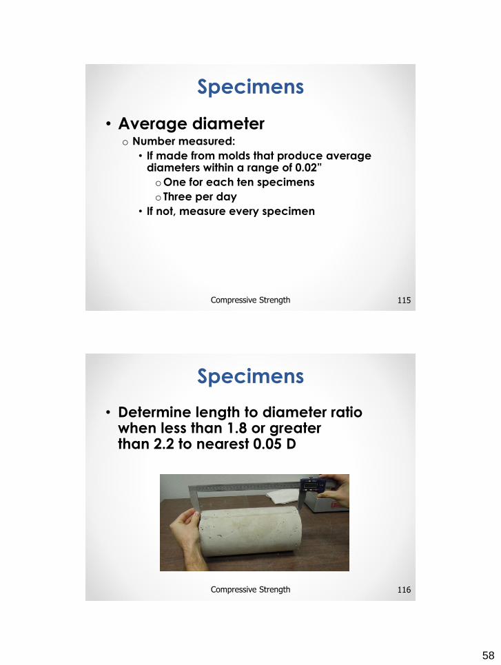
• Average diametero Number measured:
• If made from molds that produce averagediameters within a range of 0.02”
oOne for each ten specimens
o Three per day
• If not, measure every specimen
115Compressive Strength
Specimens
• Determine length to diameter ratio when less than 1.8 or greater than 2.2 to nearest 0.05 D
116Compressive Strength
Specimens
59
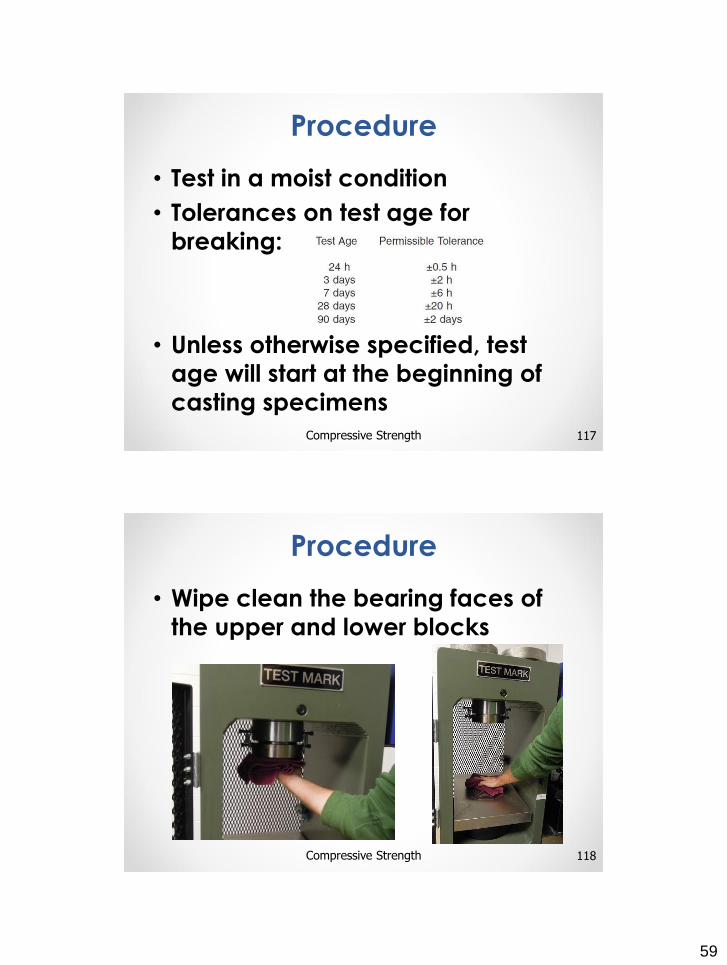
• Test in a moist condition
• Tolerances on test age for
breaking:
• Unless otherwise specified, test
age will start at the beginning of
casting specimens
117Compressive Strength
Procedure
• Wipe clean the bearing faces of
the upper and lower blocks
118Compressive Strength
Procedure
60
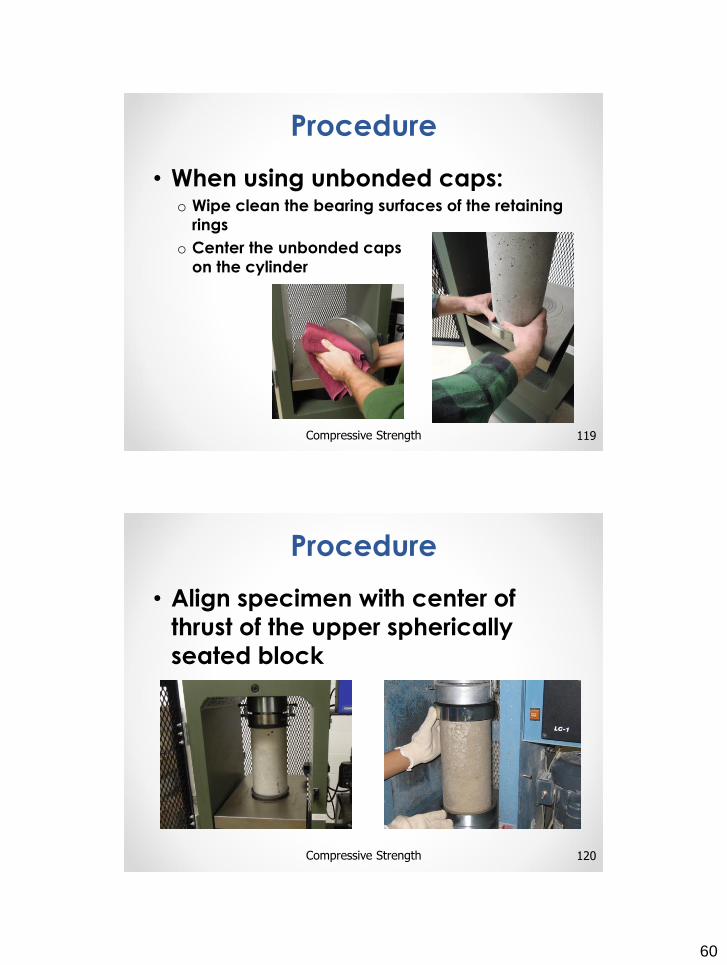
• When using unbonded caps:o Wipe clean the bearing surfaces of the retaining
rings
o Center the unbonded caps
on the cylinder
119Compressive Strength
Procedure
• Align specimen with center of
thrust of the upper spherically
seated block
120Compressive Strength
Procedure
61
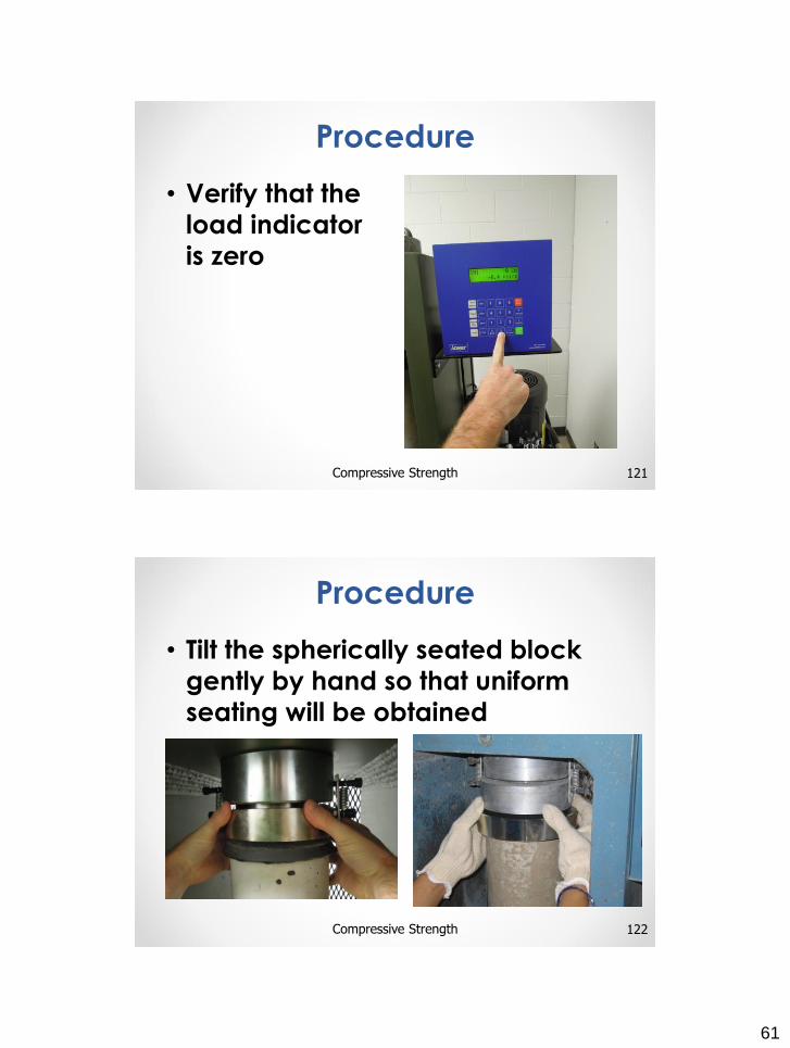
• Verify that the
load indicator
is zero
121Compressive Strength
Procedure
• Tilt the spherically seated block
gently by hand so that uniform
seating will be obtained
122Compressive Strength
Procedure
62
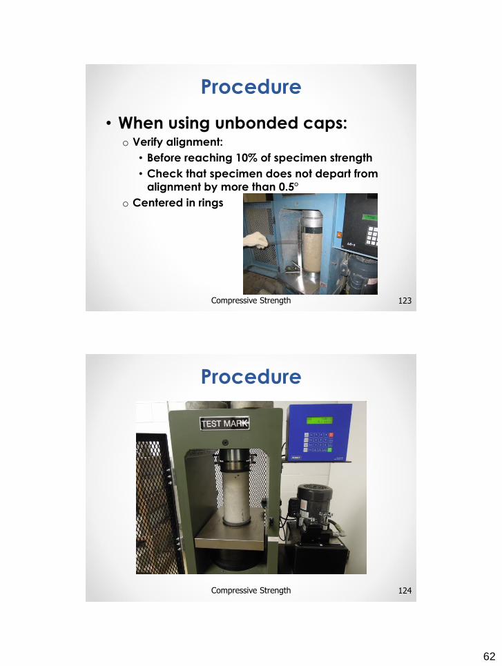
• When using unbonded caps:o Verify alignment:
• Before reaching 10% of specimen strength
• Check that specimen does not depart from
alignment by more than 0.5°
o Centered in rings
123Compressive Strength
Procedure
124Compressive Strength
Procedure
63
• Apply load continuously and
without shock
• Stress rate on the specimen of 35 +
7 psi/s
• Rate of movement maintained at
least during the latter half of the
anticipated load
• Apply load until specimen failure
125Compressive Strength
Procedure
• Compressive StrengthDivide maximum load by cross-sectional area
Cross-sectional area = 𝝅𝒅𝟐
𝟒=
𝛑 𝐝 𝐝
𝟒
d = average diameter (nearest 0.01”)
Compressive Strength = Maximum Load
Cross−sectional area
Results rounded to the nearest 10 psi
126Compressive Strength
Calculation
64
• Compressive StrengthCalculate the compressive strength of the cylinder.
Average Diameter = 4.02”
Maximum Load = 72,460
127Compressive Strength
Calculation
=𝛑 𝟒. 𝟎𝟐 𝟒. 𝟎𝟐
𝟒𝑨𝒓𝒆𝒂 =
𝛑 𝒅 𝒅
𝟒
Comp. Str =Max Load
Area=
𝟕𝟐,𝟒𝟔𝟎
𝟏𝟐.𝟔𝟗= 5,710 psi
= 12.69 in2
• Compressive StrengthCalculate the Reported Compressive Strength of the
cylinder.
Average Diameter = 6.01”
Maximum Load = 118,250
128Compressive Strength
Practice Problem
65
• When length to diameter is 1.75 or
less:
• Multiply unrounded compressive
strength by correction factor then
round to the nearest 10 psi
L/D 1.75 1.50 1.25 1.00
Factor 0.98 0.96 0.93 0.87
129Compressive Strength
Calculation
• Density (if required)o Determine by either of the following 2 methods
• Specimen Dimension Method
• Submerged Weighing Method
o For either method use a scale that is accurate to within 0.3% of the mass being measured
130Compressive Strength
Specimens
66
• Density - Specimen Dimension Methodo Remove any surface moisture with a towel
o Weigh (before capping)
o Measure length to 0.05” at 3 locations around circumference and average
o Refer to section 9.3.1 for calculation
131Compressive Strength
Specimens
• Density – Submerged Weighing Methodo Remove any surface moisture
with a towel
o Determine weight in air
o Submerge the specimen in water at a temperature of 73.5 ± 3.5°F and determine weight
o Refer to section 9.3.2 for calculation
132Compressive Strength
Specimens
67
• Density (when required)
133Compressive Strength
Calculation
P𝐬 =𝟔𝟗𝟏𝟐 𝐖
𝐋 𝐃 𝛑
Where:
Ps = specimen density (lb/ft3)
W = mass of specimen in air (lb.)
L = average measured length (in.)
D = average measured diameter
(in.)
P𝐬 =𝐖 (𝐘𝐰)
𝐖−𝐖𝐬
Where:
Ps = specimen density (lb/ft3)
W = mass of specimen in air (lb.)
Ws = apparent mass of submerged
specimen (lb.)
Yw = density of water at 73.5°F = 62.27 lb/ft3
Specimen Dimension
Method
Submerged Weighing
Method
Density
W = Mass of specimen (lbs)
V = Volume of specimen (ft3)
Volume by measuring specimen
L = Length of specimen (in.)
A = Area of specimen (in2.)
V = Volume in (ft3)
134Compressive Strength
Calculation
𝐕𝐨𝐥𝐮𝐦𝐞 =𝐋 𝐀
𝟏𝟕𝟐𝟖
𝐃𝐞𝐧𝐬𝐢𝐭𝐲 =𝐖
𝐕
68
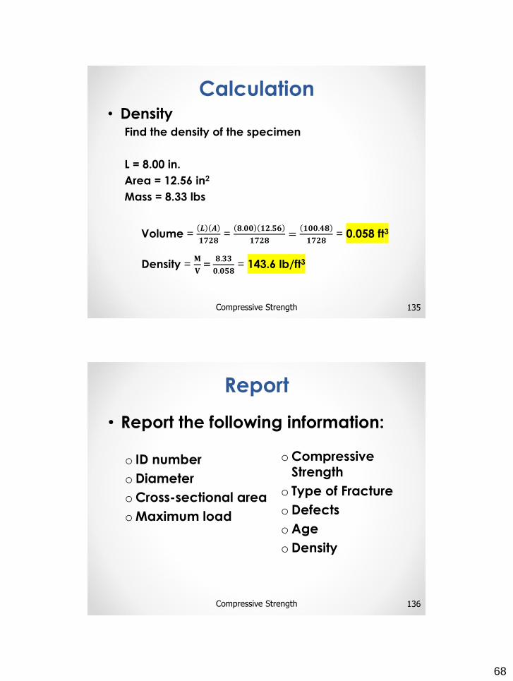
• DensityFind the density of the specimen
L = 8.00 in.
Area = 12.56 in2
Mass = 8.33 lbs
135Compressive Strength
Calculation
Volume =𝑳 𝑨
𝟏𝟕𝟐𝟖=
𝟖.𝟎𝟎 𝟏𝟐.𝟓𝟔
𝟏𝟕𝟐𝟖=
𝟏𝟎𝟎.𝟒𝟖
𝟏𝟕𝟐𝟖= 0.058 ft3
Density =𝐌
𝐕=
𝟖.𝟑𝟑
𝟎.𝟎𝟓𝟖= 143.6 lb/ft3
• Report the following information:
o ID number
oDiameter
oCross-sectional area
oMaximum load
oCompressive Strength
o Type of Fracture
oDefects
oAge
oDensity
136Compressive Strength
Report
69
137Compressive Strength
Calculation
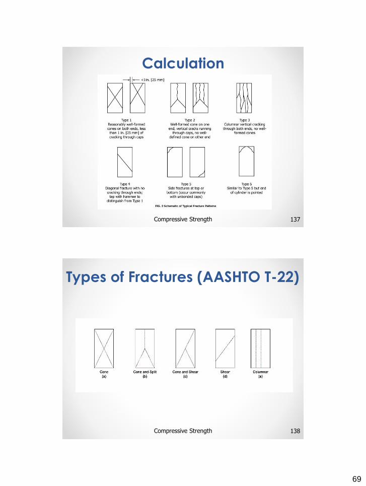
Types of Fractures (AASHTO T-22)
138Compressive Strength
70
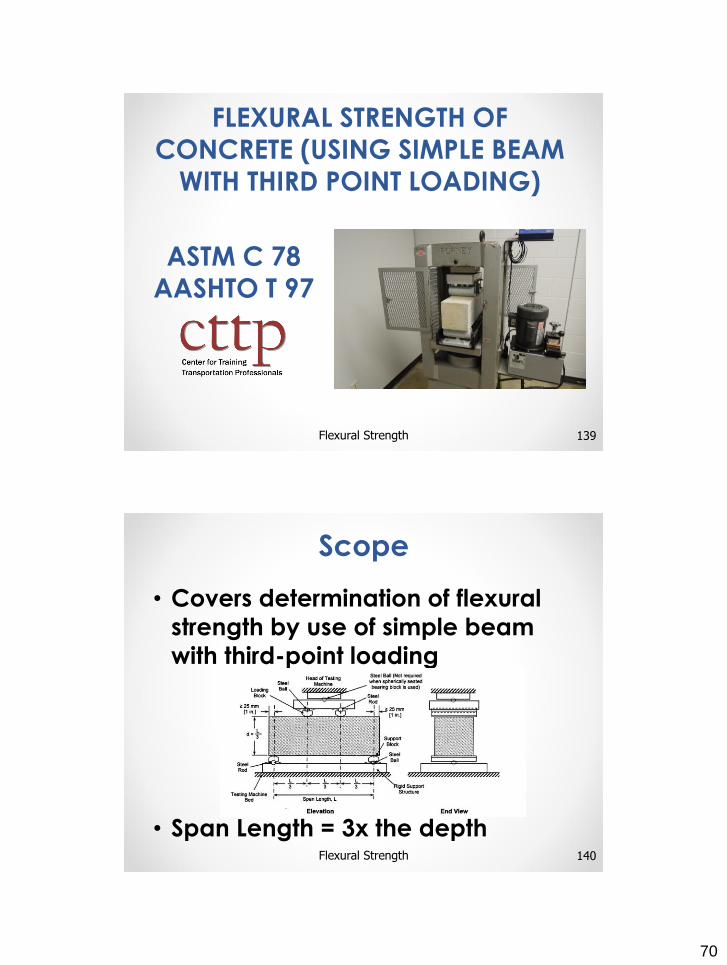
FLEXURAL STRENGTH OF
CONCRETE (USING SIMPLE BEAM
WITH THIRD POINT LOADING)
139Flexural Strength
ASTM C 78
AASHTO T 97
• Covers determination of flexural
strength by use of simple beam
with third-point loading
• Span Length = 3x the depth140Flexural Strength
Scope
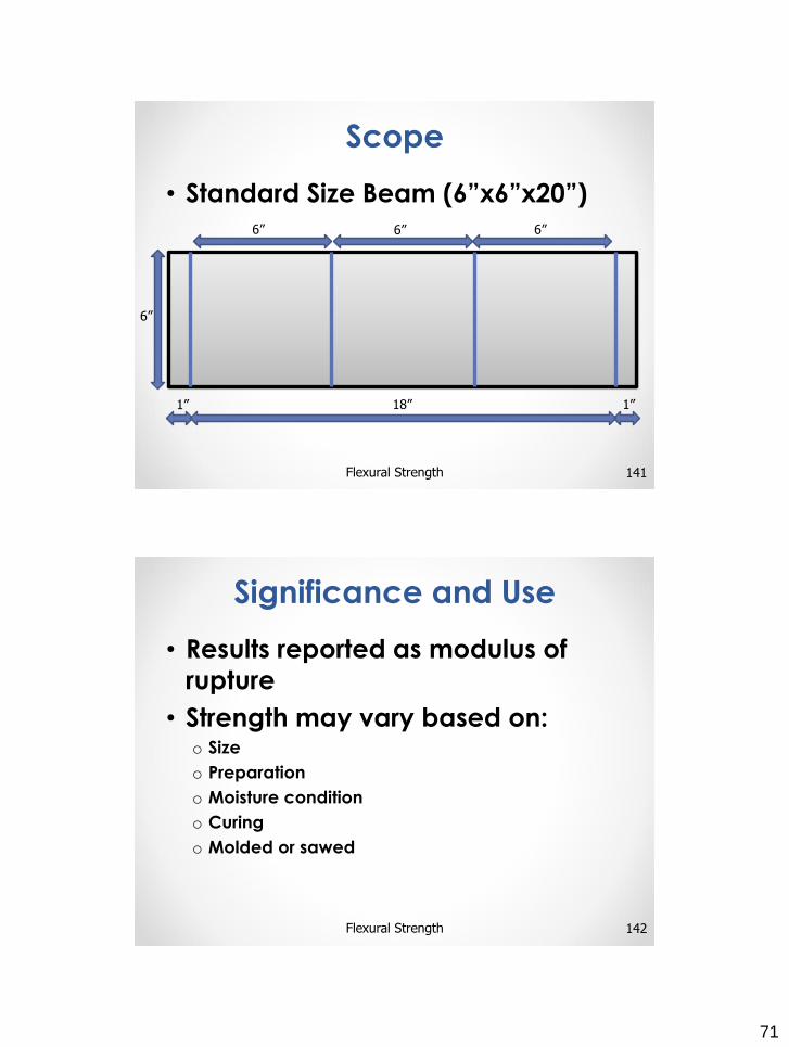
71
• Standard Size Beam (6”x6”x20”)
141Flexural Strength
Scope
18”1” 1”
6”6”6”
6”
• Results reported as modulus of
rupture
• Strength may vary based on:o Size
o Preparation
o Moisture condition
o Curing
o Molded or sawed
142Flexural Strength
Significance and Use
72
• Results o Used to determine compliance with
specifications
o Basis for proportioning, mixing and placing
o Used in testing concrete for slabs and pavements
143Flexural Strength
Significance and Use
• Shall conform to Practice E 4
• Must be capable of applying
load at uniform rate without
shock or interruption
144Flexural Strength
Apparatus
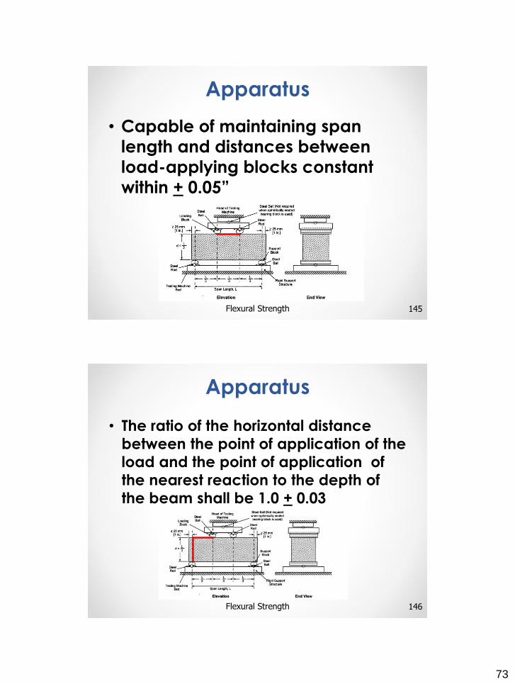
73
• Capable of maintaining span
length and distances between
load-applying blocks constant
within + 0.05”
145Flexural Strength
Apparatus
• The ratio of the horizontal distance
between the point of application of the
load and the point of application of
the nearest reaction to the depth of
the beam shall be 1.0 + 0.03
146Flexural Strength
Apparatus
74
• Loading blocks and support blockso Should not be more than 2 ½” high
o Extend full width of specimen
147Flexural Strength
Apparatus
• Test span shall be within 2% of
three times the tested depth
• Sides shall be at right angles to the
top with smooth surfaces
148Flexural Strength
Test Specimens
75
• Keep specimen moist between
removal of storage and testing
• Turn molded specimen on side for
testing
• Position sawed specimens with tension
face up or down with
respect to parent
material
149Flexural Strength
Procedure
• Center loading system in relation
to applied force
150Flexural Strength
Procedure
20”
3”3” 6”6”
Locate Middle
76
• Bring load applying
blocks into contact
and apply a load of
between 3 and 6%
of the estimated
total load
151Flexural Strength
Procedure
• Use feeler gauges (0.004” and
0.015”) to check for gaps over a
length of 1”
152Flexural Strength
Procedure
77
• Grind, cap, or use leather shims to
eliminate gaps in excess of
0.004”
• Shims• uniform to ¼” thickness
• 1 to 2” wide
• Full width of specimen
• Cap or grind only gaps
in excess of 0.015”
153Flexural Strength
Procedure
• Load specimen continuously without shock until break occurs
• Apply at a rate that constantly increases the
maximum stress on the tension face between 125 –175 psi/min until rupture
154Flexural Strength
Procedure
78
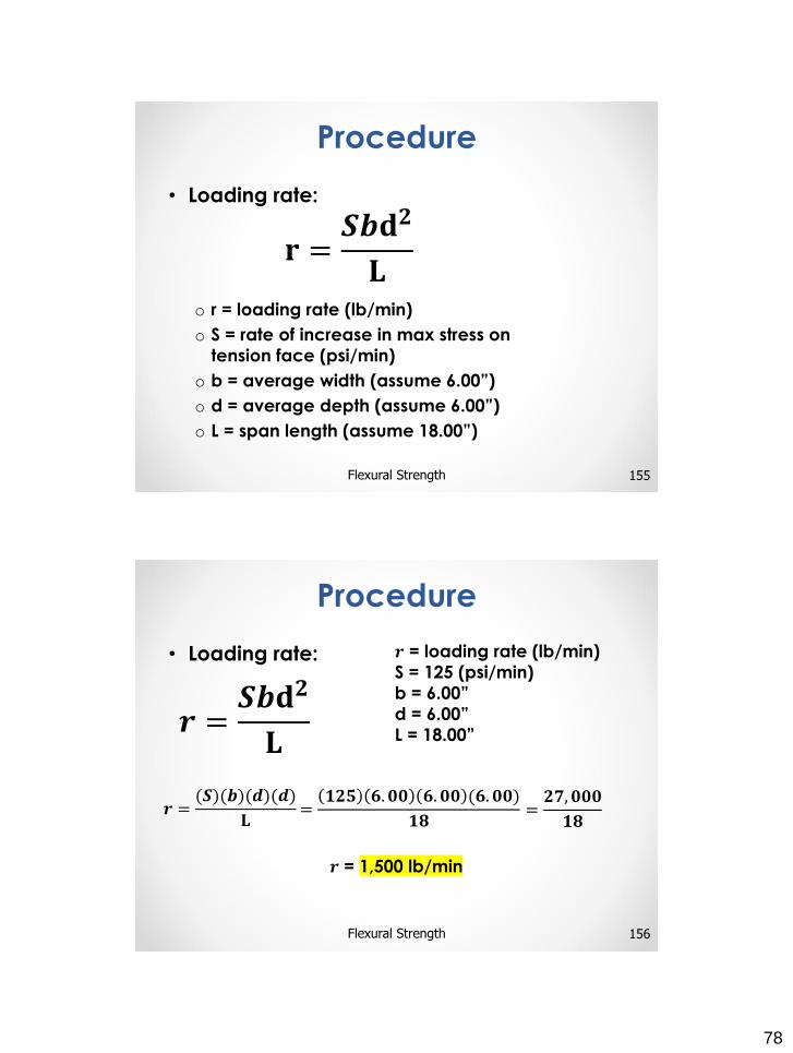
• Loading rate:
o r = loading rate (lb/min)
o S = rate of increase in max stress on
tension face (psi/min)
o b = average width (assume 6.00”)
o d = average depth (assume 6.00”)
o L = span length (assume 18.00”)
𝐫 =𝑺𝒃𝐝𝟐
𝐋
155Flexural Strength
Procedure
• Loading rate:
𝒓 =𝑺𝒃𝐝𝟐
𝐋
156Flexural Strength
Procedure
𝒓 = loading rate (lb/min)
S = 125 (psi/min)
b = 6.00”
d = 6.00”
L = 18.00”
=𝟏𝟐𝟓 𝟔. 𝟎𝟎 𝟔. 𝟎𝟎 (𝟔. 𝟎𝟎)
𝟏𝟖𝒓 =
(𝑺)(𝒃)(𝒅)(𝒅)
𝐋=𝟐𝟕, 𝟎𝟎𝟎
𝟏𝟖
𝒓 = 1,500 lb/min
79
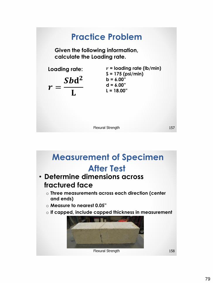
157Flexural Strength
Practice Problem
Loading rate:
𝒓 =𝑺𝒃𝐝𝟐
𝐋
𝒓 = loading rate (lb/min)
S = 175 (psi/min)
b = 6.00”
d = 6.00”
L = 18.00”
Given the following information, calculate the Loading rate.
• Determine dimensions across
fractured faceo Three measurements across each direction (center
and ends)
o Measure to nearest 0.05”
o If capped, include capped thickness in measurement
158Flexural Strength
Measurement of Specimen
After Test
80
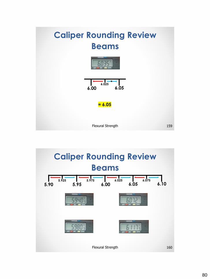
159Flexural Strength
Caliper Rounding Review
Beams
= 6.05
6.00 6.056.025
160Flexural Strength
Caliper Rounding Review
Beams
5.90 5.95 6.00 6.05 6.105.925 5.975 6.025 6.075
81
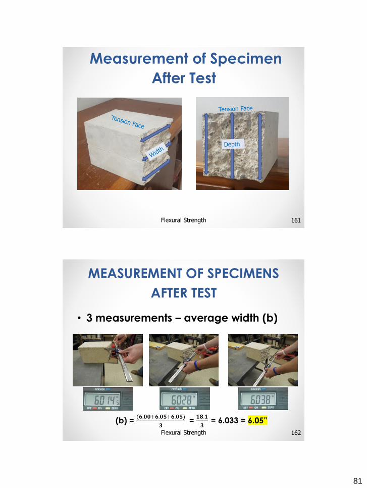
161Flexural Strength
Measurement of Specimen
After Test
• 3 measurements – average width (b)
MEASUREMENT OF SPECIMENS
AFTER TEST
162Flexural Strength
(b) = (𝟔.𝟎𝟎+𝟔.𝟎𝟓+𝟔.𝟎𝟓)
𝟑= = 6.033 𝟏𝟖.𝟏
𝟑= 6.05”
82
• 3 measurements – average depth (d)
163Flexural Strength
Measurement of Specimens
After Test
(d) = (𝟔.𝟎𝟎+𝟔.𝟎𝟎+𝟔.𝟎𝟓)
𝟑= = 6.017 𝟏𝟖.𝟎𝟓
𝟑= 6.00”
• Fracture in middle third:
o R = modulus of rupture (psi)
o P = maximum applied load
o L = span length (in.)
o b = average width (nearest 0.05”)
o d = average depth (nearest 0.05”)
Calculate to the nearest 5 psi
𝐑 =𝐏𝐋
𝐛𝐝𝟐
164Flexural Strength
Calculation
83
165Flexural Strength
Calculation
P = 8260
L = 18”
b = 6.05”
d = 6.00”
=(𝟖𝟐𝟔𝟎)(𝟏𝟖)
(𝟔. 𝟎𝟓)(𝟔. 𝟎𝟎)(𝟔. 𝟎𝟎)=𝟏𝟒𝟖, 𝟔𝟖𝟎
𝟐𝟏𝟕. 𝟖
𝐑 =𝐏𝐋
𝐛𝐝𝟐
𝐑 =𝐏𝐋
𝐛𝐝𝟐
Calculate to the nearest 5 psi
R = 685 psi
= 682.64
166Flexural Strength
Practice ProblemA beam fractures within the middle third of the span
length. Given the following information, calculate the
modulus of rupture.
𝐑 =𝐏𝐋
𝐛𝐝𝟐
Maximum applied load = 9780
Span Length = 18.0”
Width 1 = 6.036” Depth 1 = 5.965”
Width 2 = 6.012” Depth 2 = 5.982”
Width 3 = 5.955” Depth 3 = 5.946”
84
• Outside the middle third but within
5% of span lengtho For a standard size beam, 18 x 0.05 = 0.9”
167Flexural Strength
Measurement of Specimens
After Test
5%
5.1 – 6.0” in 5%
Tension Face
• Outside the middle third but
within 5% of span lengtho 3 measurements – average width (b)
168Flexural Strength
(b) = (𝟔.𝟎𝟓+𝟔.𝟏𝟎+𝟔.𝟏𝟎)
𝟑= = 6.083 𝟏𝟖.𝟐𝟓
𝟑= 6.10”
Measurement of Specimens
After Test
85
• Outside the middle third but
within 5% of span lengtho 3 measurements – average depth (d)
169Flexural Strength
Measurement of Specimens
After Test
(d) = (𝟔.𝟎𝟓+𝟔.𝟏𝟎+𝟓.𝟗𝟓)
𝟑= = 6.033 𝟏𝟖.𝟏
𝟑= 6.05”
• Outside the middle third but within
5% of span lengtho 3 measurements – average distance between line
of fracture and nearest support (a)
o Measure along the tension face
170Flexural Strength
Measurement of Specimens
After Test
86
• 3 measurements – average distance
between line of fracture and nearest
support (a)
171Flexural Strength
Calculation
5.4
5.7
4.8
(a) = (𝟓.𝟒+𝟓.𝟕+𝟒.𝟖)
𝟑= = 5.3”
𝟏𝟓.𝟗
𝟑
5%
5.1 – 6.0” in 5%Tension Face
• Fracture outside middle third but not more than 5% of span length:
o R = modulus of rupture (psi)
o P = maximum applied load
o b = average width (nearest 0.05”)
o d = average depth (nearest 0.05”)
o a = average distance between line of fracture and nearest support (in.)
Calculate to the nearest 5 psi
𝐑 =𝟑𝐏𝐚
𝐛𝐝𝟐
172Flexural Strength
Calculation
87
173Flexural Strength
Calculation
P = 8190
b = 6.10”
d = 6.05”
a = 5.3”
=(𝟑)(𝟖𝟏𝟗𝟎)(𝟓. 𝟑)
(𝟔. 𝟏𝟎)(𝟔. 𝟎𝟓)(𝟔. 𝟎𝟓)=
𝟏𝟑𝟎, 𝟐𝟐𝟏
𝟐𝟐𝟑. 𝟐𝟕𝟓𝟐𝟓𝐑 =
𝟑𝐏𝒂
𝐛𝐝𝟐
Calculate to the nearest 5 psi
𝐑 =𝟑𝐏𝐚
𝐛𝐝𝟐
R = 585 psi
= 583.23
174Flexural Strength
Practice ProblemA beam fractures outside the middle third but within 5% of
the span length. Given the following information,
calculate the modulus of rupture.
Maximum applied load = 10120
Distance of fracture from nearest support = 5.6”
Width 1 = 6.024” Depth 1 = 6.078”
Width 2 = 6.029” Depth 2 = 6.083”
Width 3 = 6.033” Depth 3 = 6.071”
𝐑 =𝟑𝐏𝐚
𝐛𝐝𝟐
88
• Fracture outside middle third by
more than 5% of span length:
175Flexural Strength
Calculation
5%
Discard Results
Tension Face
• Id number• Average width (to nearest 0.05”)• Average depth (to nearest 0.05”)• Span length• Maximum applied load• Modulus of rupture• Curing history and apparent moisture at time
of test• If specimens were capped, ground, or if
shims were used• Whether sawed or molded and any defects• Age of specimen
176Flexural Strength
Report