Embed Size (px)
Citation preview

Title Authors
Technical reports/
Controlling ASR Expansion by Lithium Ion PressurizedInjection Method
Technical reports/
A Study on Quality Control of Precast Concrete andInspection of Cover Depth of Precast Concrete
Technical reports/
Research and Development on Concrete Pavement that AllowsEarly Opening to Traffic ―1 DAY PAVE―
Technical reports/
Shotcrete Method Using Thixotropic Mortar for Long-RangePumping Over 1000 Meters
Construction records/
Aggressive Application of Fly-ash in Concrete to ReduceEnvironmental Burden and Improve Quality of StructuralMembers of Buildings ―Record Case of the Denki BuildingKyosoukan Site―
Construction records/
Design and Construction of Kumakawa Bridge on JobanExpressway
Concrete Journal, Vol.50, No.2, Feb. 2012
Kazunori ERA
Junichi YANAGIDA, NobuharuOHNUMA, Masaru YAMAGUCHIand Masahiro YAMADA
Souichiro KAJIMOTO, DoheiTAKAGI, Tessho KAMETANI andTadashi KOMIKADO
Junichi NODA, Yutaka ANDO andMasashi KOYANAGAWA
Tatsuya SASATANI, HiromiFUJIWARA, KazuhikoNAGASAWA and TadashiHAMAGO
Kimihiro ABE, Hidenori FUJITA,and Hiroshi TAKEMURA

Concrete Journal Vol.50, No.2, pp.155-162, Feb. 2012/ Copyright ○c Japan Concrete Institute
(email:[email protected])
Keywords: ASR, Lithium ion, Pressurized injection, EPMA, TOF-SIMS
Recently, lithium ion pressurized injection method has been spotlighted as the repair method of concrete structure which deteriorated by ASR. In this study, the effect of lithium ion on ASR expansion was investigated. The elemental analysis of the ASR gel sample to which lithium ion had been supplied was also performed by using SEM, EPMA and TOF-SIMS. The change of the physical form of the ASR gel due to the supply of lithium ion was not found by SEM observation. However, the elemental analysis by TOF-SIMS enable to obtain the element mapping of the lithium ion in ASR gel. Furthermore, the elemental analysis by EPMA and TOF-SIMS demonstrated that lithium ion by the pressurized injection method has extended to the gel.
By pre-mixing Li ions in concrete with a reactive aggregate and a Li/Na mole ratio of 0.4, ASR expansion was found to be suppressed. Also, by adding Li ions into ASR-deteriorated concrete by pressurized injection to a Li/Na mole ratio of 0.4, ASR expansion after the injection was suppressed. Although Li ions in the gel could not be detected
by using EPMA, it was shown to be feasible by
using TOF-SIMS, and elemental mapping was carried out. Elemental mapping using EPMA and TOF-SIMS
showed that Li ions introduced by pressurized injection are present in the gel. Also, the results of a quantitative elemental analysis indicated that the Li ion exists at a rate of the Li/Na molar ratio of 0.17 to 0.21 in gel.
.............. .........
Technical reports
Controlling ASR Expansion by Lithium Ion Pressurized Injection Method
Kazunori ERA*1
*1 Group Leader, Concrete Maintenance Division, Kyokuto Kowa Co., Ltd. Dr.E., JCI Member
-500
0
500
1000
1500
2000
2500
3000
3500
4000
4500
5000
5500
6000
0 50 100 150 200 250 300 350 400 450Time [days]
Expa
nsio
n [µ
]
Premixture, 0.4Premixture, 0.8Premixture, 1.2Injection, 0.4Injection, 0.6Injection, 0.8No addit ion
Figure 1: Expansion of concrete specimen
Pressurized
6 000
5 500
5 000
4 500
4 000
3 500
3 000
2 500
2 000
1 500
1 000
Figure 3: Elemental analysis on Li in ASR gel, aggregate and cement paste by TOF-SIMS
Figure 2: Elemental analysis on Na, C, Si in ASR gel, aggregate and cement paste in concrete by EPMA(EDS)
KNa
Si CaC
SEM
Aggregate
Crack
Gel
Gel
Cementpaste
Gel
Gel Li
Concrete Journal Vol.50, No.2, pp.163-170, Feb. 2012/ Copyright ○c Japan Concrete Institute
Keywords: precast concrete, quality control, concrete cover depth , electromagnetic induction
method 1. Introduction
About maintaining and controlling the high level of quality of precast concrete members (hereafter called "PCa"), related systems and examples of methods were presented. The applicability of electromagnetic induction method to measurement of cover depths of PCa members was also studied. 2. Abstract 2-1. Quality Approval Systems for PCa Members
Introduction was made about the assessment of manufacturing and quality control capabilities at PCa plants, "Quality Approval Systems for PCa Members," which is conducted by Japan Prefabricated Construction Suppliers and Manufacturers Association to ensure the quality of PCa members.
PCa plants are set to maintain necessary capabilities to manufacture PCa members through the challenge of acquiring this quality approval and passing the subsequent assessment processes. 2-2. Examples of Quality Control Methods
Quality control in manufacturing PCa members focuses on eliminating consumer's risks. The risk is attributed primarily to human errors made by
inspectors. Several examples of the recent human error preventive measures were introduced. 3. Cover Depth Control by Electromagnetic Induction Method
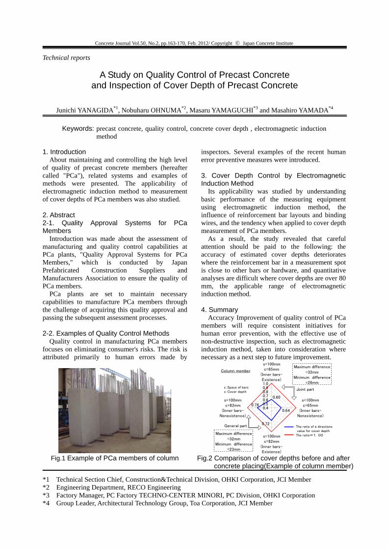
Its applicability was studied by understanding basic performance of the measuring equipment using electromagnetic induction method, the influence of reinforcement bar layouts and binding wires, and the tendency when applied to cover depth measurement of PCa members.
As a result, the study revealed that careful attention should be paid to the following: the accuracy of estimated cover depths deteriorates where the reinforcement bar in a measurement spot is close to other bars or hardware, and quantitative analyses are difficult where cover depths are over 80 mm, the applicable range of electromagnetic induction method. 4. Summary
Accuracy Improvement of quality control of PCa members will require consistent initiatives for human error prevention, with the effective use of non-destructive inspection, such as electromagnetic induction method, taken into consideration where necessary as a next step to future improvement.
Technical reports
A Study on Quality Control of Precast Concrete and Inspection of Cover Depth of Precast Concrete
Junichi YANAGIDA*1, Nobuharu OHNUMA*2, Masaru YAMAGUCHI*3 and Masahiro YAMADA*4
*1 Technical Section Chief, Construction&Technical Division, OHKI Corporation, JCI Member *2 Engineering Department, RECO Engineering *3 Factory Manager, PC Factory TECHNO-CENTER MINORI, PC Division, OHKI Corporation *4 Group Leader, Architectural Technology Group, Toa Corporation, JCI Member
0.72
0.64
0.60
0.760.40.50.60.70.80.91.0
s=100mmc=65mm
(Inner bars-Existence)
s=100mmc=65mm
(Inner bars-Nonexistence)
s=100mmc=82mm
(Inner bars-Existence)
s=100mmc=82mm
(Inner bars-Nonexistence)
Column memberMaximum difference
=32mmMinimum difference
=26mm
Maximum difference
=32mmMinimum difference
=23mm
s:Space of barsc:Cover depth
Joint part
General part The ratio of a directions value for cover depthThe ratio=1.00
Fig.2 Comparison of cover depths before and after concrete placing(Example of column member)
Fig.1 Example of PCa members of column

Concrete Journal Vol.50, No.2, pp.171-179, Feb. 2012/ Copyright ○c Japan Concrete Institute
Keywords: 1 DAY PAVE,Concrete pavement,Early opening to traffic,Skid resistance,Test pavement,Flexural strength,Surface smoothness
The JCA committee on Pavement examined the
concrete pavement (We call it “1DAY PAVE” as follows.) that a traffic opening was enabled in curing period of less than 1 day with general materials. We found a kind of the cement, a curing condition and a mix proportion condition by a laboratory test. Moreover we carried out two test pavements and confirmed their placeability and their change of surface conditions of in-service road. Table -1 shows the mix proportion of 1DAY PAVE concrete.
Table-1 Mix proportion of 1 DAY PAVE
About 1DAY PAVE concrete, becoming dull at fresh time was not confirmed by the visual observation. The flexural strength was 4.7N/mm2 in a day. The skid resistance value of the 1DAY PAVE concrete was 88 BPN.
We carried out the test pavement of 1DAY PAVE on the yard road in the Kumagaya factory of Taiheiyo Cement Corp. Co., Ltd. in May, 2009. The pavement section consists of mechanical stabilized base of thickness 20cm and 1DAY PAVE concrete surface course of thickness 20cm. The joint spacing is 6m as well as the joint spacing of an existing concrete pavement. The scale of the examination pavement is 256m2 of 64m in length and 4m in width. The execution speed of the concrete pave was about 12.8m/h and it was about 75 hours in time from a traffic regulation to a traffic opening (actual work 42 hours). Figure -1 shows the execution situation. The flexural strength was 5.69N/mm2 in a day. As the result, it was assumed that the flexural strength reached the traffic opening strength in about 15 hours. The surface smoothness was 1.93mm before the traffic opening and it was 1.99mm in one year later. In addition, as a result of investigation one year later, quantity of rutting was 1.30mm and there was no joint faulting. The skid resistance was less than 0.3 μ at a certain
measurement point. We evaluated the influence that the time of the broom marks on the ground finish gave to the improvement of the skid resistance in laboratory test. The test body which imitated a road surface of the examination pavement was less than BPN value 50 by the abrasion of the tire after 15,000 rounds by the rotary ravelling test machine, but the test body which was able to delay the broom marks on the ground insertion time was in a healthy state. From these results, we found the possibility that could improve the skid resistance by delaying the broom marks on the ground insertion time.
In Uji River dike sky edge paving work (Kyoto Fushimi-ku side main thoroughfare district), we carried out the test pavement of 1 DAY PAVE in February, 2011. The execution scale is 30m in length, 3m in width and joint spacing 5m. We did not use the wire meshes and the dowel bars. The pavement section consists of the base of thickness 10cm using a hydraulic mechanically stabilized slag and the concrete surface course of thickness 20cm. Three pieces of curing sheet were used for thermal effect. The execution speed was 20.0m/h at the same level as the yard examination pavement. The flexural strength was 3.94N/mm2, and it was higher than the traffic opening strength. In addition, the surface smoothness was 2.15mm. There was no crack and the road surface condition was good. The skid resistance value was 0.39μ. We are going to confirm how the skid resistance value changes in the future.
Fig-1 The execution situation
Technical reports
Research and Development on Concrete Pavement that Allows Early Opening to Traffic
―1 DAY PAVE―
Junichi NODA*1, Yutaka ANDO*2 and Masashi KOYANAGAWA*3
*1 Research & Development Laboratory, JAPAN CEMENT ASSOCIATION *2 Cement/Concrete Research Laboratory, SUMITOMO OSAKA CEMENT CO., LTD, JCI Member *3 Professor, Department of Regional Environment Science, Tokyo University of Agriculture., JCI Member
Unit Content (kg/m3) W/C s/a
W C S G
35% 42% 155 443 733 1012

Concrete Journal Vol.50, No.2, pp.180-186, Feb. 2012/ Copyright ○c Japan Concrete Institute
(email:[email protected])
0.00.20.40.60.81.01.21.41.61.82.02.22.42.62.83.0
0 10 20 30 40 50 60 70 80 90 100圧送距離(×10m)
圧送圧力(
MPa
)
10(㍑/min) 20(㍑/min)30(㍑/min) 40(㍑/min)50(㍑/min)
図-2 1,000m圧送における各流量条件の圧力測定値
Pumping pressure
(MPa
)
Pumping range(×10m)
liter liter liter
liter liter
Fig.2 Pressure measurement under various flow conditions in 1,000 pumping
①ミキサによりモルタル
材料を製造し、ポンプで
1,000m圧送 ②モルタル材料と急
結剤の流量をコンピ
ュータシステムで制
御
③モルタル材料・急結剤・圧縮空気をノズルで合流し、吹付け
図-1 施工フロー
パネルコンピュータ
Compressed air
Quick setting agent
Compressor
Quick setting agent pump
Panel computer Grout mixer
Provided agitator Material pump
(1) Produce mortar material with a mixer for pumping at a range of 1,000 m
Material
Fig.1 Execution flow
(2) Control the flow of mortar material and quick setting agent using a computer system
Spray nozzle
(3) Mix mortar material, quick setting agent and compressed air at the nozzle and spray the mixture
Keywords: long-range pumping, thixotropy, patch repair, strengthening, slope failure
prevention, high strength shotcrete, We describe a new technique of mortar spraying method, or shotcrete method using thixotropic mortar, to enable a long range pumping operation using light weight hose at low pressure which was not made possible by means of existing techniques.
Mortar material gains thixotropy when it has thixotropic material added. Specifically, being pressurized during pumping, mortar material releases a moderate amount of water, which was contained inside by thixotropic material, decreasing in viscosity, thus reducing its friction resistance against the hose inner surface. After pumping has been done, the material gets released from the pressure, which in turn lets the thixotropic material absorb water again, thus the viscosity restores to its original state. By taking advantage of this phenomenon induced by the difference in pressure environments where water coming in and going out of the thixotropic material, long range pumping becomes a reality. As a result, we realized pumping over 1,000 m using 1.5 inch hose at a maximum pressure of 3.0 MPa or even lower. To obtain thixotropic mortar, we mixed cement and thixotropic material at a mass ratio of 64.5 : 35.5, cement and fine aggregate at a volume ratio of 1:1, keeping the additive mass ratio of highly-effective water reducing agent to powder (cement and thixotropic material) at 0.5% to 2.0% and mass ratio of water to powder at 40.4%. At the tip of spray nozzle, we mixed quick setting agent at a volume ratio of 3% to 5% to the mortar material.
Our execution technique is to mix mortar material, quick setting agent and compressed air together at the nozzle tip to spray the mixture. The mixing ratio of mortar material to quick setting agent is automatically controlled by a panel computer. Execution flow is illustrated in Fig.1.
We describe a long range pumping operation based on our test and its result. We mounted a pressure gage every 100 m on a 1,000 m long, 1.5 inch broad hose to visually check the gage pressure while performing pumping at a specified flow. The flow rate was set at 10 to 50 liter per
minute as the test conditions. The test result (Fig.2) indicates the pump root pressure of 2.6 MPa at zero meters under the condition of 50 liter per minute flow, whereas the maximum pumping flow at execution is 50 liter per minute. This result proves that pumping over 1,000 m is feasible at a pump root pressure of 3.0 MPa or
less.
Technical reports
Shotcrete Method Using Thixotropic Mortar for Long-Range Pumping Over 1000 Meters
Tatsuya SASATANI*1, Hiromi FUJIWARA*2, Kazuhiko NAGASAWA*3 and Tadashi HAMAGO*4
*1 Acting Head of a Section, Production Engineering Division, Nittoc Construction Co.,Ltd., JCI Member *2 Prof., Faculty of Engineering, Utsunomiya University, JCI Member *3 Graduate School of Engineering, Utsunomiya University, JCI Member *4 Group Leader, Production Engineering Division, Nittoc Construction Co.,Ltd.

Concrete Journal Vol.50, No.2, pp.188-193, Feb. 2012/ Copyright ○c Japan Concrete Institute
Keywords: lyash, Mass Concrete, CFT (Concrete-Filled Steel Tube), Enviromental load
reduction, heat of hydration, thermal crack
Large amount of Fly-Ash (FA) was applied to the concrete of CFT elements of the building as well as to the mass concrete of the underground structure. The overall quality of structural members was improved by the positive effect of FA concrete such as the improvement of flowability of fresh concrete, reduction of heat of hydration and increase of water-tightness performance of hardened concrete. Furthermore, preserving the quality of fly-ash helped supply stable FA ready-mixed concrete of excellent quality throughout the execution period.
Construction records
Aggressive Application of Fly-ash in Concrete to Reduce Environmental Burden and Improve Quality of Structural Members of Buildings
―Record Case of the Denki Building Kyosoukan Site―
Souichiro KAJIMOTO*1, Dohei TAKAGI*2, Tessho KAMETANI*3 and Tadashi KOMIKADO*4
*1 Engineering group,Construction Department,Takenaka Corporation *2 General Construction Manager,Construction field office,Takenaka Corporation *3 Section chief,Plant and structural design team,Architecture department,West Japan Engineering
Consultant *4 Plant and structural design team,Architecture department,West Japan Engineering Consultants
0
5
10
15
20
25
30
35
40
45
50
55
60
0.0 0.5 1.0 1.5 2.0 2.5 3.0 3.5 4.0 4.5 5.0 5.5 6.0 6.5 7.0経過日数 (日)
コンクリート温
度 (℃
)
N-FA0%
N-FA30%
最大 42.8℃
最大 51.0℃
抑制効果▲8.2℃
配合条件W/C=50%スランプ=12±1cm空気量=4.5±1.0%
Max
Mineffect
PreparationW/C=50%Slump=12±1cmAir=4.5±1.0%co
ncre
te te
mpe
ratu
re(℃
)
lapsed days
0
5
10
15
20
25
30
35
40
45
50
55
60
0.0 0.5 1.0 1.5 2.0 2.5 3.0 3.5 4.0 4.5 5.0 5.5 6.0 6.5 7.0経過日数 (日)
コンクリート温
度 (℃
)
N-FA0%
N-FA30%
最大 42.8℃
最大 51.0℃
抑制効果▲8.2℃
配合条件W/C=50%スランプ=12±1cm空気量=4.5±1.0%
Max
Mineffect
PreparationW/C=50%Slump=12±1cmAir=4.5±1.0%co
ncre
te te
mpe
ratu
re(℃
)
lapsed days
Fig.1 increment of simplified adiabatic temperature rise
water-binder ratio (W/B)
0
0.02
0.04
0.06
0.08
0.1
0.12
0.14
30.0 32.0 34.0 36.0 38.0 40.0 42.0 44.0
/
A工場 N+FA120kg/m3
B工場 N
Am
ount
of b
leed
ing(
cm3 /c
m2 )
Fig.2 Water-binder, Amount of bleeding
Fig.3 Minimum value of cracking index distribution
1.08
0.87
0
0.2
0.4
0.6
0.8
1
1.2
FA(置換率20%) NFA(Substitute-rate20%)Min
imum
val
ue o
f cra
ckin
g in
dex
Fig.4 Compared Minimum value of cracking index
Crack range(mm)
number
opening other than opening
~below0.1mm 24 2
more than 0.1mm~below 0.2mm 29 7
more than 0.2mm~below 0.3mm 10 2
more than 0.3mm~below 0.4mm 1 1
Table 1 search result of Crack

Concrete Journal Vol.50, No.2, pp.194-199, Feb. 2012/ Copyright ○c Japan Concrete Institute
Keywords: corrugated steel web, cantilever erection, thermal stress analysis, expansive concrete
1. Introduction
Kumakawa Bridge (Fig-1) is a three-span PC box-girder bridge using corrugated steel web on Joban Expressway across the Kumakawa River in Okuma town, Fukushima prefecture. Using corrugated steel web enables to reduce the girder weight because they replace heavy concrete web and to lessen site works. It also unnecessitates rebar installation and formwork for concrete web. The bridge length is 259.0m and the central span length is 118.0m, which is the longest span for corrugated steel web bridges in Tohoku branch of East Nippon Expressway Co. 2. Design
We designed the sections on the piers with concrete web. By doing so, the volume of steel is largely reduced because concrete diaphragms unnecessitate high and thick steel webs there. It has economical merit compared with using corrugated steel web for the sections.
Since the sections on the piers had massive concrete whose strength was 40N/mm2, there was a great concern of harmful thermal cracks. Therefore, the sections on the piers were designed to reduce concrete volume by adopting hollow cross section. Fig-2 shows the adopted section that reduced concrete volume by about 32m3. Concrete for the sections on the piers was placed in
three stages to lessen the concrete volume per pour and to lower the temperature of concrete. Furthermore, air-cooling was carried out at the second lift to lower the temperature of concrete further. Expansive concrete was adopted for upper slab at the third lift to prevent concrete cracking.
The effects of these steps were confirmed by thermal stress analysis.
3. Construction
Kumakawa Bridge was constructed by balanced cantilever erection. During the erection, daily
average temperature needs to be higher than 4℃ for grouting work. But it was below 4℃ in winter at the construction area when the cantilever erection was carried out. Therefore, grouting had not been conducted for four months until daily average temperature went up to over 4℃. While there was no grout in the sheath, humidity control system for PC strands by sending air was carried out to prevent rust from occurring.
The camber calculation for the cantilever erection was conducted by using measured young’s modulus and unit weight of concrete, and also considered shear deformation of girder.
Expansive concrete was adopted to slabs in the mid-span jointing segment, the upper slab in side span constructed with hanging scaffolding and concrete guardrails as well as the upper slab of the sections on the piers to prevent concrete cracking.
Construction records
Design and Construction of Kumakawa Bridge on Joban Expressway
Kimihiro ABE*1, Hidenori FUJITA*2, and Hiroshi TAKEMURA*3
*1 Construction Manager, Iwaki Construction Office, Tohoku Branch, East Nippon Expressway Co. *2 Project Manager, Construction Division, Osaka Branch, PS Mitsubishi Co. *3 Group Leader, Design Division, Tokyo Branch, PS Mitsubishi Co.
Fig.2 Form of column capital
Fig.1 Kumakawa Bridge
4 - 4 54
4 5
5 - 5
3
2
11
2
3
2 - 2 3 - 31 - 1
1500 2000 1500
6300 750 4800 750 2000750 800 7502000
1500
1500
2000
2000
1500
1500
5000
1500 2000 1500
1500
3500
2500
15001800
1700
2500