Embed Size (px)
Citation preview

Available online at www.worldscientificnews.com
WSN 80 (2017) 1-17 EISSN 2392-2192
Concrete Foundation Systems and Footings
1Allen P. Nangan II, 2Tomas U. Ganiron Jr, 3Doyce T. Martinez 1Fletcher Construction, Port Vila, Vanuatu, South Pacific
2College of Architecture, Qassim University, Buraidah City, KSA
3Department of Chemical and Materials Engineering, Auckland University, NZ
E-mail address: [email protected] , [email protected] ,
ABSTRACT
This paper discusses a list of information and issues that causes of structural failure in the
foundations and footings of a building. When a load is gradually applied on a foundation, settlement
occurs which is almost elastic to begin with. At the ultimate load, general shear failure occurs when a
plastic yield surface develops under the footing, extending outward and upward to the ground surface,
and catastrophic settlement or rotation of the foundation occurs. Foundation failure is caused by
multiple reasons such as poor soil preparation, water problems, dry heat, large trees and plumbing
issues Foundation failure is where the foundation settles below level of original construction to a point
where damages has occurred such as veneer cracking, interior sheetrock cracking, separations in the
veneer and misaligning doors to name a few common symptoms
Keywords: Building, footings, foundation, geotechnical engineering, structural systems
1. INTRODUCTION
The importance of a foundation in a structure is a major consideration in the
construction of any building, whether it is intended for residential, commercial and industrial
purposes. The load of the structure is the primary consideration in the design.
Buildings, dams, monuments, bridges, piers, walls, roads, and any construction

World Scientific News 80 (2017) 1-17
-2-
requiring a stable base for successful execution requires accurate structural analysis as well as
the in-depth review of the supporting geology. Historical examples of failed design in
foundation construction are legion (Becker, 1997). The leaning tower of Pisa is a well-known
early anomaly, built at a site with inadequate geological load bearing capacity coupled with
poor structural foundation design (Buchanan, 2011). The Austin Dam failure in Pennsylvania
in 1911 is a more recent example which involved correct geological load bearing assessment
but failed to recognize base rock sliding and uplift risks as well as poor structural concrete
design. At least one case of foundation failure was intentional; some early constructions on
permafrost deliberately utilized the slow thawing of the frozen soil and resultant settling of
the building to create subsurface basements without the need for excavation. Fortunately more
recent extreme foundations failures are rare. This is largely due to the recognized need for
correct geological site analysis and testing as well as better structural design and construction
processes.
Two broad categories of modern foundation design can be defined, the shallow form
and the deep form (Chopra, 1974). Shallow foundations include slabs, stem walls, footings,
basements, and other forms which can be created using surface excavation techniques. Deep
foundations refer to driven pilings and piers, shafts, caissons, injected borings, and forms
which derive stability from subsurface geological formations and soils underlying soil and
rock are the geotechnical contribution of the design process (Buchanan, 2010). A site survey
is conducted to identify the geological materials present. This survey may include testing and
analysis of shallow surface samples as well as deep core samples taken from drilled borings,
and review of data from existing related formations. The resulting geotechnical report will
identify compressively and shear load capacities available for the various layers of soils and
rock formations present at the proposed construction site. It may also identify settlement
potential, moisture swelling, erosion concerns, and freeze/thaw processes. This may result in
modifying, moving, or even abandoning a construction project site due to inadequate
foundation support capacities of the local geology (Clark, 1998).
As the ultimate foundation of foundations, constant information exchange and
collaboration throughout the design and analysis process will continue to be the driving
influence for continual improvement in this vital construction element (Dunham, 1954).
2. TYPES OF FOUNDATIONS
All foundations are divided into two categories: shallow foundations and deep
foundations. The words shallow and deep refer to the depth of soil in which the foundation is
made. Shallow foundations can be made in depths of as little as 3ft (1 m), while deep
foundations can be made at depths of 60 - 200ft (20 – 65 m).
Shallow foundations are also called spread footings or open footings. The 'open' refers
to the fact that the foundations are made by first excavating all the earth till the bottom of the
footing, and then constructing the footing. During the early stages of work, the entire footing
is visible to the eye and is, therefore, called an open foundation (Dashti, 2009). The idea is
that each footing takes the concentrated load of the column and spreads it out over a large area
so that the actual weight of the soil does not exceed the safe bearing capacity of the soil
(Dutta, 2004).

World Scientific News 80 (2017) 1-17
-3-
Figure 1. Individual footings awaiting concreting of the footing column
There are several kinds of shallow footings: individual footings, strip footings, and raft
foundations. In cold climates, shallow foundations must be protected from freezing. This is
because water in the soil around the foundation can freeze and expand, thereby damaging the
foundation (Ellingwood, 2007). These foundations should be built below the frost line, which
is the level on the ground above which freezing occurs. If they cannot be built below the frost
line, they should be protected by insulation: normally a little heat from the building will
permeate into the soil and prevent freezing.
As shown in Figure 1, individual footings are one of the most simple and common types
of foundations. These are used when the load of the building is carried by columns. Usually,
each column will have its own footing. The footing is just a square or rectangular pad of
concrete on which the column sits. To get a very rough idea of the size of the footing, the
engineer will take the total load on the column and divide it by the safe bearing capacity
(SBC) of the soil. For example, if a column has a vertical load of 10 T, and the SBC of the
soil is 10 T/m2, then the area of the footing will be 1 m
2 (Elgar, 1951). In practice, the
designer will look at many other factors before preparing a construction design for the
footing.
In Figure 2, individual footings are usually connected by a plinth beam. This is a
horizontal beam that is built at the ground or below ground level. Strip footings are commonly
found in load-bearing masonry construction, and act as a long strip that supports the weight of
an entire wall. These are used where the building loads are carried by entire walls rather than
isolated columns, such as in older buildings made of masonry. In Figure 3, raft foundations,
also called mat foundations, are most often used when basements are to be constructed. In a
raft foundation, the entire basement floor slab acts as the foundation; the weight of the
building is spread evenly over the entire footprint of the building. It is called a raft because
the building is like a vessel that 'floats' in a sea of soil (Grinda, 1997).

World Scientific News 80 (2017) 1-17
-4-
Figure 2. Individual footings connected by a plinth beam
Figure 3. Raft Foundation

World Scientific News 80 (2017) 1-17
-5-
Mat foundations are used where the soil is a week, and therefore building loads have to
be spread over a large area, or where columns are closely spaced, which means that if
individual footings were used, they would touch each other (Ganiron Jr, 2016).
A pile is basically a long cylinder of a strong material such as concrete that is pushed
into the ground so that structures can be supported on top of it (Ganiron Jr, 2016).
Pile foundations are used in the following situations: (a) when there is a layer of weak
soil at the surface shown in Figure 4. This layer cannot support the weight of the building, so
Loads of the buildings have to bypass this layer and be transferred to the layer of stronger soil
or rock that is below the weak layer and (b) when a building has very heavy, concentrated
loads, such as in a high-rise structure.
Figure 4. Pile Foundation
In end bearing piles, the bottom end of the pile rests on a layer of, especially strong soil
or rock. The load of the building is transferred to the pile onto the strong layer. In a sense, this
pile acts like a column. The key principle is that the bottom end rests on the surface which is
the intersection of a weak and strong layer. The load, therefore, by passes the weak layer and
is safely transferred to the strong layer (Ganiron Jr, 2015).
Friction piles work on a different principle. The pile transfers the load of the building to
the soil across the full height of the pile, by friction. In other words, the entire surface of the
pile, which is cylindrical in shape, works to transfer the forces to the soil.
To visualize how this works, imagine people are pushing a solid metal rod of say 4mm
diameter into a tub of frozen ice cream. Once people have pushed it in, it is strong enough to

World Scientific News 80 (2017) 1-17
-6-
support some load. The greater the embedment depth in the ice cream, the more load it can
support. This is very similar to how a friction pile works. In a friction pile, the amount of load
a pile can support is directly proportionate to its length. In practice, however, each pile resists
load by a combination of end bearing and friction.
3. SITE DRAINAGE AND THE DANGER TO FOOTINGS OF STRUCTURES
When homeowners think of all the things with the potential to damage the footings and
foundation of their home or commercial property, chances are, homeowners not thinking
about the site itself. In fact, even if homeowner keeps guttering and downpipes in good repair,
poor site drainage can contribute to foundation damage.
Damp, soggy lawns are the least of your troubles if site drainage on your property is
compromised. More than just a muddy lawn, the homeowner may also be facing damage to
footings or foundations. When water begins to pool around footings or the soil surrounding a
foundation is consistently waterlogged, the extended presence of moisture can and will
weaken foundations, damage footings and lead to structural damage. There are several
different factors which can contribute to poor site drainage, which may not always be
immediately obvious to the untrained eye.
Slopes can lend visual interest to homeowner property, for instance, but they can also
send water sluicing to the lowest point. Depending on the presence of man-made drainage
systems and the condition of the soil upon which homeowner structure is built, water may be
retained in the soil for extended periods of time. Slope-related drainage problems can usually
be addressed with the addition of ditches or even a subsurface drain.
Human traffic can also be an unexpected source of site drainage issues. Just building
homeowner home or commercial building can compact the soil and diminish its ability to
absorb water properly. Compounded by foot traffic and the presence of vehicles, compacted
soil becomes even less absorbent over time
If there are standing puddles on homeowner property long after the rain has stopped, it’s
fairly obvious to even those without experience in the building trades, that there may be a
problem afoot. Site drainage issues which present the most danger to footings and building
foundations are those which aren’t so easily spotted. For property owners who are planning a
new construction project, drainage problems may not even be apparent until the structure is
erected.
This is where the assistance of a professional building inspector can be invaluable.
Unlike builders and landscaping professionals with a vested financial interest in finding fault
with site drainage on homeowner property, a professional building inspector has no financial
stake in the findings of their report. Whether homeowners getting ready to begin a new
construction project on homeowner new property or are simply concerned about the quality of
drainage on your existing site, working with a professional building inspection company can
help homeowner avoid danger to footings and damage to foundations by detecting and
addressing site drainage issues before they become a costly and difficult problem to fix.

World Scientific News 80 (2017) 1-17
-7-
4. FOUNDATION MAINTENANCE AND FOOTING PERFORMANCE
Buildings can and often do move. This movement can be up, down, lateral or rotational.
The fundamental cause of movement in buildings can usually be related to one or more
problems in the foundation soil. It is important for the homeowner to identify the soil type in
order to ascertain the measures that should be put in place in order to ensure that problems in
the foundation soil can be prevented, thus protecting against building movement.
This research is designed to identify causes of soil-related building movement and to
suggest methods of prevention of resultant cracking in buildings.
4. 1. Soil Types
The types of soils usually present under the topsoil in land zoned for residential
buildings can be split into two approximate groups – granular and clay. Quite often,
foundation soil is a mixture of both types. The general problems associated with soils having
granular content are usually caused by erosion. Clay soils are subject to saturation and
swell/shrink problems (Ganiron Jr, 2014). Classifications for a given area can generally be
obtained by application to the local authority, but these are sometimes unreliable and if there
is doubt, a geotechnical report should be commissioned. As most buildings suffering
movement problems are found on clay soils, there is an emphasis on classification of soils
according to the amount of swell and shrinkage they experience with variations of water
content. Table 1 shows the general definitions of site classes.
Table 1. General Definitions of Site Classes
Class Foundation
A Most sand and rock sites with little or no ground movement
from moisture changes
S Slightly reactive clay sites with only slight ground movement
from moisture changes
M Moderately reactive clay or silt sites, which can experience
moderate ground movement from moisture changes
H Highly reactive clay sites, which can experience high ground
movement from moisture changes
E Extremely reactive sites, which can experience extreme
ground movement from moisture changes
A to P Filled sites
P
Sites which include soft soils, such as soft clay or silt or loose sands;
landslip; mine subsidence; collapsing soils; soils subject to erosion;
reactive sites subject to abnormal moisture conditions or sites which
cannot be classified otherwise

World Scientific News 80 (2017) 1-17
-8-
4. 2. Causes of movement
All the data gathered treated using the following tools. There are two types of settlement
that occur as a result of construction: (a) Immediate settlement occurs when a building is first
placed on its foundation soil, as a result of compaction of the soil under the weight of the
structure (Ganiron Jr, 2017). The cohesive quality of clay soil mitigates against this, but the
granular (particularly sandy) soil is susceptible. (b) Consolidation settlement is a feature of
clay soil and may take place because of the expulsion of moisture from the soil or because of
the soil's lack of resistance to local compressive or shear stresses.This will usually take place
during the first few months after construction, but has been known to take many years in
exceptional cases. These problems are the province of the builder and should be taken into
consideration as part of the preparation of the site for construction. All soils are prone to
erosion, but sandy soil is particularly susceptible to being washed away. Even clay with a
sand component of say 10% or more can suffer from erosion (Hardin, 1972).
This is particularly a problem in clay soils. Saturation creates a bog like suspension of
the soil that causes it to lose virtually all of its bearing capacity. To a lesser degree, sand is
affected by saturation because saturated sand may undergo a reduction in volume –
particularly imported sand fill for bedding and blinding layers. However, this usually occurs
as immediate settlement and should normally be the province of the builder.
All clays react to the presence of water by slowly absorbing it, making the soil increase
in volume. The degree of increase varies considerably between different clays, as does the
degree of decrease during the subsequent drying out caused by fair weather periods. Because
of the low absorption and expulsion rate, this phenomenon will not usually be noticeable
unless there are prolonged rainy or dry periods, usually of weeks or months, depending on the
land and soil characteristics. The swelling of soil creates an upward force on the footings of
the building, and shrinkage creates subsidence that takes away the support needed by the
footing to retain equilibrium.
Shear failure occurs when the foundation soil does not have sufficient strength to
support the weight of the footing. There are two major post-construction causes (Kishida,
1966): (a) Significant load increase. (b) Reduction of lateral support of the soil under the
footing due to erosion or excavation. (c) In clay soil, shear failure can be caused by saturation
of the soil adjacent to or under the footing.
Trees and shrubs that are allowed to grow in the vicinity of footings can cause
foundation soil movement in two ways: (a) Roots that grow under footings may increase in
cross-sectional size, exerting upward pressure on footings. (b) Roots in the vicinity of
footings will absorb much of the moisture in the foundation soil, causing shrinkage or
subsidence.
4. 3. Unevenness of Movement
The types of ground movement described above usually occur unevenly throughout the
building’s foundation soil. Settlement due to construction tends to be uneven because of
differing compaction of foundation soil prior to construction and differing moisture content of
foundation soil prior to construction.
Movement due to non-construction causes is usually more uneven still. Erosion can
undermine a footing that traverses the flow or can create the conditions for shear failure by
eroding soil adjacent to a footing that runs in the same direction as the flow.

World Scientific News 80 (2017) 1-17
-9-
Saturation of clay foundation soil may occur where subfloor walls create a dam that
makes water pond. It can also occur wherever there is a source of water near footings in clay
soil. This leads to a severe reduction in the strength of the soil which may create local shear
failure.
Seasonal swelling and shrinkage of clay soil affect the perimeter of the building first,
then gradually spreads to the interior. The swelling process will usually begin at the uphill
extreme of the building, or on the weather side where the land is flat. Swelling gradually
reaches the interior soil as absorption continues. Shrinkage usually begins where the sun’s
heat is greatest (Liu, 1997).
4. 4. Effects of Uneven Soil Movement on Structures
The types of ground movement described above usually occur unevenly throughout the
building’s foundation soil. Settlement due to construction tends to be uneven because of
differing compaction of foundation soil prior to construction and differing moisture content of
foundation soil prior to construction (Merritt, 1954). Erosion removes the support from under
footings, tending to create subsidence of the part of the structure under which it occurs.
Brickwork walls will resist the stress created by this removal of support by bridging the gap
or cantilevering until the bricks or the mortar bedding fail. Older masonry has little resistance.
Evidence of failure varies according to circumstances and symptoms may include (Shiba,
2007): (a) Step cracking in the mortar beds in the body of the wall or above/below openings
such as doors or windows. (b) Vertical cracking in the bricks (usually but not necessarily in
line with the vertical beds). Isolated piers affected by erosion or saturation of foundations will
eventually lose contact with the bearers they support and may tilt or fall over. The floors that
have lost this support will become bouncy, sometimes rattling ornaments etc.
Swelling foundation soil due to rainy periods first lifts the most exposed extremities of
the footing system, then the remainder of the perimeter footings while gradually permeating
inside the building footprint to lift internal footings (Tsang, 2012). This swelling first tends to
create a dish effect, because the external footings are pushed higher than the internal ones.
The first noticeable symptom may be that the floor appears slightly dished. This is often
accompanied by some doors binding on the floor or the door head, together with some
cracking of cornice miters. In buildings with timber flooring supported by bearers and joists,
the floor can be bouncy. Externally there may be visible dishing of the hip or ridge lines. As
the moisture absorption process completes its journey to the innermost areas of the building,
the internal footings will rise. If the spread of moisture is roughly even, it may be that the
symptoms will temporarily disappear, but it is more likely that swelling will be uneven,
creating a difference rather than a disappearance in symptoms. In buildings with timber
flooring supported by bearers and joists, the isolated piers will rise more easily than the strip
footings or piers under walls, creating noticeable doming of flooring (Velotso, 1971).
As the weather pattern changes and the soil begin to dry out, the external footings will
be first affected, beginning with the locations where the sun's effect is strongest. This has the
effect of lowering the external footings. The doming is accentuated and cracking reduces or
disappears where it occurred because of dishing, but other cracks open up. The roof lines may
become convex (Weaver, 1993). Doming and dishing are also affected by weather in other
ways. In areas where warm, wet summers and cooler dry winters prevail, water migration
tends to be toward the interior and doming will be accentuated, whereas where summers are
dry and winters are cold and wet, migration tends to be toward the exterior and the underlying
World Scientific News 80 (2017) 1-17
-10-
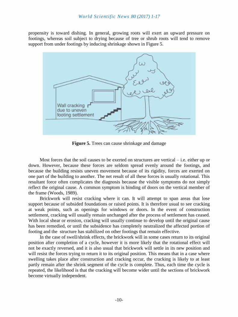
propensity is toward dishing. In general, growing roots will exert an upward pressure on
footings, whereas soil subject to drying because of tree or shrub roots will tend to remove
support from under footings by inducing shrinkage shown in Figure 5.
Figure 5. Trees can cause shrinkage and damage
Most forces that the soil causes to be exerted on structures are vertical – i.e. either up or
down. However, because these forces are seldom spread evenly around the footings, and
because the building resists uneven movement because of its rigidity, forces are exerted on
one part of the building to another. The net result of all these forces is usually rotational. This
resultant force often complicates the diagnosis because the visible symptoms do not simply
reflect the original cause. A common symptom is binding of doors on the vertical member of
the frame (Woods, 1989).
Brickwork will resist cracking where it can. It will attempt to span areas that lose
support because of subsided foundations or raised points. It is therefore usual to see cracking
at weak points, such as openings for windows or doors. In the event of construction
settlement, cracking will usually remain unchanged after the process of settlement has ceased.
With local shear or erosion, cracking will usually continue to develop until the original cause
has been remedied, or until the subsidence has completely neutralized the affected portion of
footing and the structure has stabilized on other footings that remain effective.
In the case of swell/shrink effects, the brickwork will in some cases return to its original
position after completion of a cycle, however it is more likely that the rotational effect will
not be exactly reversed, and it is also usual that brickwork will settle in its new position and
will resist the forces trying to return it to its original position. This means that in a case where
swelling takes place after construction and cracking occur, the cracking is likely to at least
partly remain after the shrink segment of the cycle is complete. Thus, each time the cycle is
repeated, the likelihood is that the cracking will become wider until the sections of brickwork
become virtually independent.

World Scientific News 80 (2017) 1-17
-11-
With repeated cycles, once the cracking is established, if there is no other complication,
it is normal for the incidence of cracking to stabilize, as the building has the articulation it
needs to cope with the problem. This is by no means always the case, however, and
monitoring of cracks in walls and floors should always be treated seriously. The upheaval
caused by a growth of tree roots under footings is not a simple vertical shear stress. There is
a tendency for the root to also exert lateral forces that attempt to separate sections of
brickwork after initial cracking has occurred
The normal structural arrangement is that the inner leaf of brickwork in the external
walls and at least some of the internal walls (depending on the roof type) comprise the load-
bearing structure on which any upper floors, ceilings and the roof are supported. In these
cases, it is internally visible cracking that should be the main focus of attention, however,
there are a few examples of dwellings whose external leaf of masonry plays some supporting
role, so this should be checked if there is any doubt. In any case, externally visible cracking is
important as a guide to stresses on the structure generally, and it should also be remembered
that the external walls must be capable of supporting themselves
Timber or steel framed buildings are less likely to exhibit cracking due to swell/shrink
than masonry buildings because of their flexibility. Also, the doming/dishing effects tend to
be lower because of the lighter weight of walls. The main risks to framed buildings are
encountered because of the isolated pier footings used under walls.
Where erosion or saturation cause a footing to fall away, this can double the span which
a wall must bridge. This additional stress can create cracking in wall linings, particularly
where there is a weak point in the structure caused by a door or window opening. It is,
however, unlikely that framed structures will be so stressed as to suffer serious damage
without first exhibiting some or all of the above symptoms for a considerable period. The
same warning period should apply in the case of upheaval. It should be noted, however, that
where framed buildings are supported by strip footings there is only one leaf of brickwork and
therefore the externally visible walls are the supporting structure for the building. In this case,
the subfloor masonry walls can be expected to behave as full brickwork walls.
Because the load-bearing structure of a brick veneer building is the frame that makes up
the interior leaf of the external walls plus perhaps the internal walls, depending on the type of
roof, the building can be expected to behave as a framed structure, except that the external
masonry will behave in a similar way to the external leaf of a full masonry structure.
4. 5. Water service and Drainage
Where a water service pipe, a sewer or stormwater drainage pipe is in the vicinity of a
building, a water leak can cause erosion, swelling or saturation of the susceptible soil. Even a
minuscule leak can be enough to saturate a clay foundation. A leaking tap near a building can
have the same effect. In addition, trenches containing pipes can become watercourses even
though backfilled, particularly where broken rubble is used as fill. Water that runs along these
trenches can be responsible for serious erosion, interstate seepage into subfloor areas and
saturation. Pipe leakage and trench water flow also encourage tree and shrub roots to the
source of water, complicating and exacerbating the problem.
Poor roof plumbing can result in large volumes of rainwater being concentrated in a
small area of soil: Incorrect falls in roof guttering may result in overflows, as may gutters
blocked with leaves etc. Corroded guttering or downpipes can spill water to the ground.
Downpipes not positively connected to a proper stormwater collection system will direct a

World Scientific News 80 (2017) 1-17
-12-
concentration of water to soil that is directly adjacent to footings, sometimes causing large-
scale problems such as erosion, saturation, and migration of water under the building
In general, most cracking found in masonry walls is a cosmetic nuisance only and can
be kept in repair or even ignored. Table 2 shows the classification of damage with reference to
wall and figure 6 emphasize the cracking in concrete floors, however, because wall cracking
will usually reach the critical point significantly earlier than cracking in slabs.
4. 6. Prevention Cure
Where building movement is caused by water service, roof plumbing, sewer or
stormwater failure, the remedy is to repair the problem. It is prudent, however, to consider
also rerouting pipes away from the building where possible, and relocating taps to positions
where any leakage will not direct water to the building vicinity. Even where gully traps are
present, there is sometimes sufficient spill to create erosion or saturation, particularly in
modern installations using smaller diameter PVC fixtures. Indeed, some gully traps are not
situated directly under the taps that are installed to charge them, with the result that water
from the tap may enter the backfilled trench that houses the sewer piping. If the trench has
been poorly backfilled, the water will either pond or flow along the bottom of the trench. As
these trenches usually run alongside the footings and can be at a similar depth, it is not hard to
see how any water that is thus directed into a trench can easily affect the foundation’s ability
to support footings or even gain entry to the subfloor area.
In all soils, there is the capacity for water to travel on the surface and below it. Surface
water flows can be established by inspection during and after heavy or prolonged rain. If
necessary, a grated drain system connected to the stormwater collection system is usually an
easy solution. It is, however, sometimes necessary when attempting to prevent water
migration that testing is carried out to establish water table height and subsoil water flows.
Table 2. Classification of damage with reference to wall
Description of typical damage and required repair Approximate crack
width limit
Damage
category
Hairline cracks <0.1 mm 0
Fine cracks which do not need repa <1 mm 1
Cracks noticeable but easily filled. Doors and
windows stick slightl <5 mm 2
Cracks can be repaired and possibly a small
amount of wall will need to be replaced. Doors
and windows stick. Service pipes can fracture,
Weathertightness often impaired
5–15 mm (or a
number of crack 3
mm or more in one
group)
3
Extensive repair work involving breaking out and
replacing sections of walls,
Extensive repair
work involving
breaking out and
replacing sections
of walls,
4

World Scientific News 80 (2017) 1-17
-13-
It is essential to remember that the soil that affects footings extends well beyond the
actual building line. Watering of garden plants, shrubs and trees causes some of the most
serious water problems. For this reason, particularly where problems exist or are likely to
occur, it is recommended that an apron of paving be installed around as much of the building
perimeter as necessary. This paving should extend outwards a minimum of 900 mm (more in
highly reactive soil) and should have a minimum fall away from the building of 1:60. The
finished paving should be no less than 100 mm below brick vent bases.
It is prudent to relocate drainage pipes away from this paving, if possible, to avoid
complications from future leakage. If this is not practical, earthenware pipes should be
replaced by PVC and backfilling should be of the same soil type as the surrounding soil and
compacted to the same density. Except in areas where freezing of water is an issue, it is wise
to remove taps in the building area and relocate them well away from the building –
preferably not uphill from it. It may be desirable to install a grated drain at the outside edge of
the paving on the uphill side of the building. If subsoil drainage is needed this can be installed
under the surface drain. In buildings with a subfloor void such as where bearers and joists
support flooring, insufficient ventilation creates ideal conditions for condensation, particularly
where there is little clearance between the floor and the ground. Condensation adds to the
moisture already present in the subfloor and significantly slows the process of drying out.
Installation of an adequate subfloor ventilation system, either natural or mechanical, is
desirable. Although this Building Technology File deals with cracking in buildings, it should
be said that subfloor moisture can result in the development of other problems, notably.
Water that is transmitted into masonry, metal or timber building elements causes
damage and/or decay to those elements. High subfloor humidity and moisture content create
an ideal environment for various pests, including termites and spiders. Where high moisture
levels are transmitted to the flooring and walls, an increase in the dust mite count can ensue
within the living areas. Dust mites, as well as dampness in general, can be a health hazard to
inhabitants, particularly those who are abnormally susceptible to respiratory ailments
The ideal vegetation layout is to have lawn or plants that require only light watering
immediately adjacent to the drainage or paving edge, then more demanding plants, shrubs and
trees spread out in that order. Overwatering due to misuse of automatic watering systems is a
common cause of saturation and water migration under footings. If it is necessary to use these
systems, it is important to remove garden beds to a completely safe distance from buildings.
As shown in figuren 6, where a tree is causing a problem of soil drying or there is the
existence or threat of upheaval of footings, if the offending roots are subsidiary and their
removal will not significantly damage the tree, they should be severed and a concrete or metal
barrier placed vertically in the soil to prevent future root growth in the direction of the
building. If it is not possible to remove the relevant roots without damage to the tree, an
application to remove the tree should be made to the local authority. A prudent plan is to
transplant likely offenders before they become a problem. State departments overseeing
agriculture can give information regarding root patterns, the volume of water needed and a
safe distance from buildings of most species. Botanic gardens are also sources of information.
Excavation around footings must be properly engineered. Soil supporting footings can
only be safely excavated at an angle that allows the soil under the footing to remain stable.
This angle is called the angle of repose (or friction) and varies significantly between soil types
and conditions. Removal of soil within the angle of repose will cause subsidence.

World Scientific News 80 (2017) 1-17
-14-
Figure 6. Gardens for a reactive site
4. 7. Remediation
Where erosion has occurred that has washed away soil adjacent to footings, a soil of the
same classification should be introduced and compacted to the same density. Where footings
have been undermined, augmentation or other specialist work may be required. Remediation
of footings and foundations is generally the realm of a specialist consultant. Where isolated
footings rise and fall because of swell/shrink effect, the homeowner may be tempted to
alleviate floor bounce by filling the gap that has appeared between the bearer and the pier
with blocking. The danger here is that when the next swell segment of the cycle occurs, the

World Scientific News 80 (2017) 1-17
-15-
extra blocking will push the floor up into an accentuated dome and may also cause local shear
failure in the soil. If it is necessary to use blocking, it should be by a pair of fine wedges and
monitoring should be carried out fortnightly
5. CONCLUSIONS
Foundation problems can be caused by both homeowners and mother nature. No matter
if homeowner lived in the same home for years or have purchased a newer home, it is good to
know the causes and signs of a failing foundation. Unfortunately, mother nature can cause
foundations to fail and a homeowner can't do much about it. Knowing the signs and getting
homeowner foundation fixed by a professional foundation contractor early can potentially
save money. Most foundation problems are caused by the soil surrounding a home.
Throughout the year, the soil expands and contracts from moisture and temperature levels.
Foundations fail when there is too much water or not enough. Sections of the soil can have
different moisture levels causing the soil to swell and shrink at various locations. Some
sections of the soil can become much drier or wetter than other parts causing stress on your
home's foundation. These inconsistencies in the soil generally result from overloading, poor
water management, faulty compaction, abundance of organic materials, and erosion
References
[1] Anastasopoulos, I., & Gazetas, G. (2007). Foundation–structure systems over a
rupturing normal fault: Part II. Analysis of the Kocaeli case histories. Bulletin of
Earthquake Engineering, 5(3), 277-301
[2] Becker, D. E. (1997). Eighteenth Canadian geotechnical colloquium: Limit states design
for foundations. Part II. Development for the national building code of
Canada. Canadian Geotechnical Journal, 33(6), 984-1007
[3] Buchanan, A., Carradine, D., Beattie, G., & Morris, H. (2011). Performance of houses
during the Christchurch earthquake of 22 February 2011. Bulletin of the New Zealand
Society for Earthquake Engineering, 44(4), 342-357
[4] Buchanan, A. H., & Newcombe, M. P. (2010). The performance of residential houses in
the Darfield (Canterbury) earthquake. Bulletin of the New Zealand Society for
Earthquake Engineering, 43(4), 387
[5] Chopra, A. K., & Gutierrez, J. A. (1974). Earthquake response analysis of multistorey
buildings including foundation interaction. Earthquake Engineering & Structural
Dynamics, 3(1), 65-77
[6] Clark, J. I. (1998). The settlement and bearing capacity of very large foundations on
strong soils: 1996 RM Hardy keynote address. Canadian Geotechnical Journal, 35(1),
131-145
[7] Dashti, S., Bray, J. D., Pestana, J. M., Riemer, M., & Wilson, D. (2009). Mechanisms of
seismically induced settlement of buildings with shallow foundations on liquefiable
soil. Journal of geotechnical and geoenvironmental engineering, 136(1), 151-164

World Scientific News 80 (2017) 1-17
-16-
[8] Dunham, J. W. (1954). Pile foundations for buildings. In Proceedings of the American
Society of Civil Engineers (Vol. 80, No. 1, pp. 1-21). ASCE.
[9] Dutta, S. C., Bhattacharya, K., & Roy, R. (2004). Response of low-rise buildings under
seismic ground excitation incorporating soil–structure interaction. Soil Dynamics and
Earthquake Engineering, 24(12), 893-914
[10] Ellingwood, B. R., Smilowitz, R., Dusenberry, D. O., Duthinh, D., Lew, H. S., &
Carino, N. J. (2007). Best practices for reducing the potential for progressive collapse in
buildings. Gaithersburg: National Institute of Standards and Technology.
[11] Elgar, W. H. (1951). Foundations for houses and other small structures. Architectural
Press.
[12] Grinda, M. (1997). Some experiences with attack of microorganisms on wooden
constructions supporting foundations of houses and bridges. Document-the
International Research Group on Wood Preservation (Sweden).
[13] Ganiron Jr, T. U. (2016). A Case Study of Site Conditions and Ground Stability of
Town Homes. International Journal of Smart Home, 10(1), 207-216
[14] Ganiron Jr, T. U. (2016). Development and Efficiency of Prefabricated Building
Components. International Journal of Smart Home, 10(6), 85-94
[15] Ganiron Jr, T. U. (2015). Design and Management Features of Ecological
Sanitation. International Journal of u-and e-Service, Science and Technology, 8(8), 41-
54
[16] Ganiron Jr, T. U., & Almarwae, M. (2014). Prefabricated Technology in a Modular
House. International Journal of Advanced Science & Technology, 73
[17] Ganiron Jr, T. U. (2017). Performance of Community Water Supply Management
towards Designing Water Safety Plan. World News of Natural Sciences, 10, 10-25
[18] Hardin, B. O., & Drnevich, V. P. (1972). Shear modulus and damping in soils:
measurement and parameter effects. Journal of Soil Mechanics & Foundations Div, 98
(sm6)
[19] Jewell, E. G. (1995). U.S. Patent No. 5,402,614. Washington, DC: U.S. Patent and
Trademark Office.
[20] Kishida, H. (1966). Damage to reinforced concrete buildings in Niigata city with special
reference to foundation engineering. Soils and Foundations, 6(1), 71-88
[21] Liu, L., & Dobry, R. (1997). Seismic response of shallow foundation on liquefiable
sand. Journal of geotechnical and geoenvironmental engineering, 123(6), 557-567
[22] Merritt, R. G., & Housner, G. W. (1954). Effect of foundation compliance on
earthquake stresses in multistory buildings. Bulletin of the Seismological Society of
America, 44(4), 551-569
[23] Shiba, Y., Yokoi, M., & Hwang, D. S. (2007). Development of a ground-source heat
pump system with ground heat exchanger utilizing the cast-in-place concrete pile
foundations of buildings

World Scientific News 80 (2017) 1-17
-17-
[24] Tsang, H. H., Lo, S. H., Xu, X., & Neaz Sheikh, M. (2012). Seismic isolation for low‐to‐medium‐rise buildings using granulated rubber–soil mixtures: numerical
study. Earthquake engineering & structural dynamics, 41(14), 2009-2024
[25] Veletsos, A. S., & Wei, Y. T. (1971). Lateral and rocking vibration of footings. Journal
of Soil Mechanics & Foundations Div.
[26] Weaver, M. E., & Matero, F. M. (1993). Conserving buildings: Guide to techniques and
materials. Wiley.
[27] Woods, J. T., Woods, J. D., Woods, P. F., & Woods, F. T. (1989). U.S. Patent No.
4,817,353. Washington, DC: U.S. Patent and Trademark Office.
( Received 08 June 2017; accepted 02 July 2017 )


![SUBCHAPTER 11 [1105.3] 685 Foundation Piers Title 27 / Subchapter 11. 250 [1112.4] 722 Footings, Foundation Piers, Foundation Walls and Pile Caps [1112.5] 723 Subgrade for Footings,](https://img.pdfslide.us/doc/110x75/5a7232c07f8b9aa2538d6d1c/subchapter-11-11053-685-foundation-piers-title-27-subchapter-11-250-11124.jpg)