Embed Size (px)
Citation preview
December 3, 2012
Mitchell Community College
MCC Aerospace Engineering and Technology
CRITICAL DESIGN REVIEW ROCKSAT-C
ROCKSAT-C 2013 1

Critical Design Review – Pegasis ll Mission Statement Concept
Organizational Chart Expected Results
Theories and Concepts
Design Descriptions Requirements Mechanical
De-scopes & Off-Ramps Electrical
Software
Prototyping Analysis Power
Prototyping Interfacing
Mass
Manufacturing Mechanical Electrical
Software
ROCKSAT-C 2013 2
Testing
System Electrical
Mechanical Software
Risks Changes since CDR Critical
User-Guide Compliance
Table Logistics
Project Management
Schedule Budget
Work Breakdown Schedule
Conclusion
ROCKSAT-C 2013 3
Mission Overview
Presented By: Patrick Mencias-Lewis
PEGASIS II
ROCKSAT-C 2013 4

MISSION STATEMENT
Our goal is to power space-based instrumentation systems by passively generating energy from transducers of a proprietary design. Energy will be harvested from the rocket flight, solar rays, and other sources. This will be accomplished by building a more robust and simplistic payload using transducers with increased efficiency and improved design characteristics. Results may lower cost and power requirements for space science by reducing the weight of electrical components.
ROCKSAT-C 2013 5
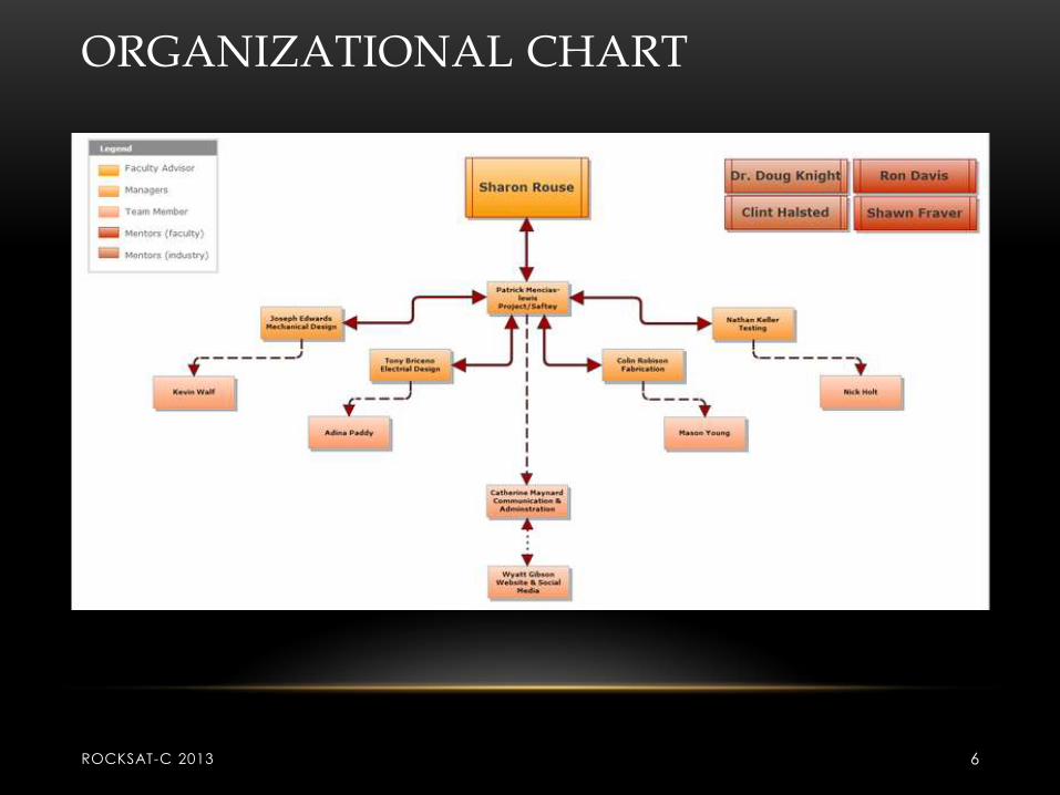
ORGANIZATIONAL CHART
ROCKSAT-C 2013 6
THEORIES AND CONCEPTS
• Electromagnetic transducers will utilize
Faraday’s Law.
• Solar transducers will utilize Photoelectric
effect.
• Peltier coolers will use solar transducer to act
as a heat sink for microprocessors
• Piezoelectric effect
ROCKSAT-C 2013 7
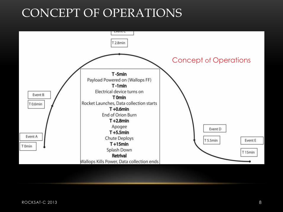
CONCEPT OF OPERATIONS
Concept of Operations
ROCKSAT-C 2013 8
CONCEPT OF OPERATIONS
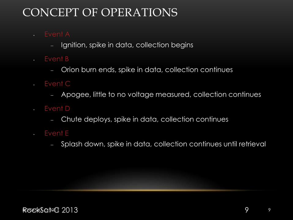
• Event A
Ignition, spike in data, collection begins
• Event B
Orion burn ends, spike in data, collection continues
• Event C
Apogee, little to no voltage measured, collection continues
• Event D
Chute deploys, spike in data, collection continues
• Event E
Splash down, spike in data, collection continues until retrieval
RockSat-C 2013 9 ROCKSAT-C 2013 9
EXPECTED RESULTS
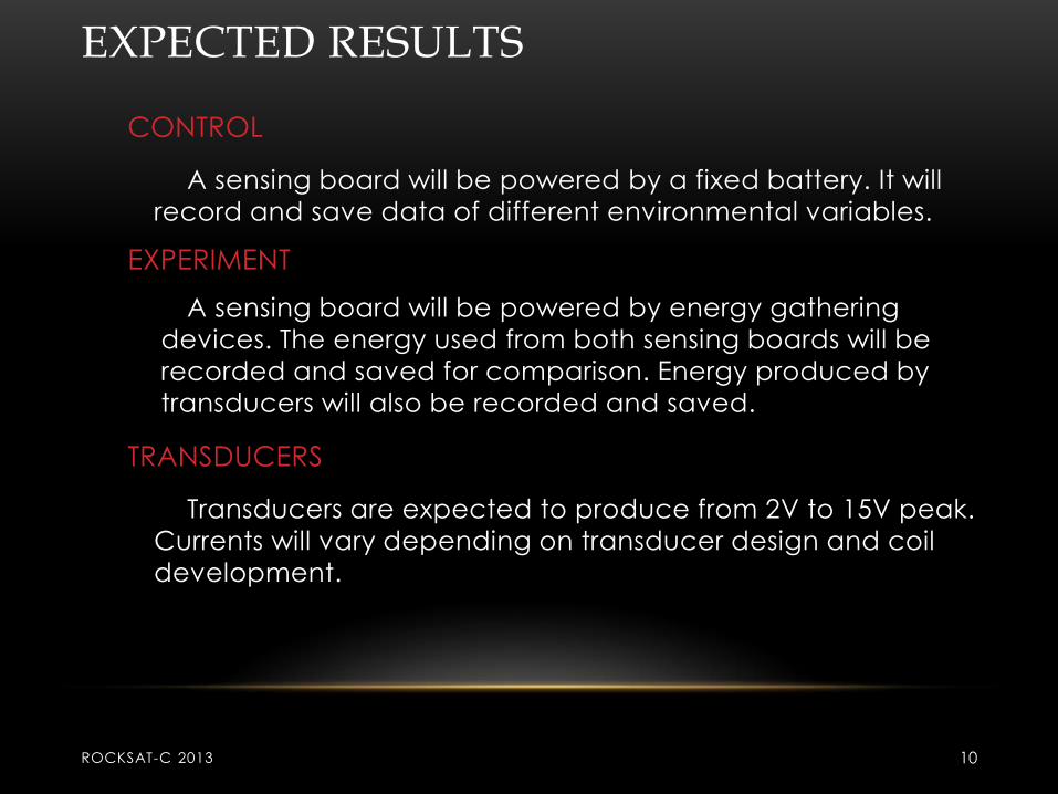
CONTROL
A sensing board will be powered by a fixed battery. It will
record and save data of different environmental variables.
EXPERIMENT
A sensing board will be powered by energy gathering
devices. The energy used from both sensing boards will be
recorded and saved for comparison. Energy produced by
transducers will also be recorded and saved.
TRANSDUCERS
Transducers are expected to produce from 2V to 15V peak.
Currents will vary depending on transducer design and coil
development.
ROCKSAT-C 2013 10

Mechanical Description
Presented By: Joseph Edwards
PEGASIS II
ROCKSAT-C 2013 11

• All transducers are to be completed as
designed.
• May implement a fractal design coil to
harvest the earth’s electromagnetic field.
ROCKSAT-C 2013 12
De-Scopes & Off Ramps
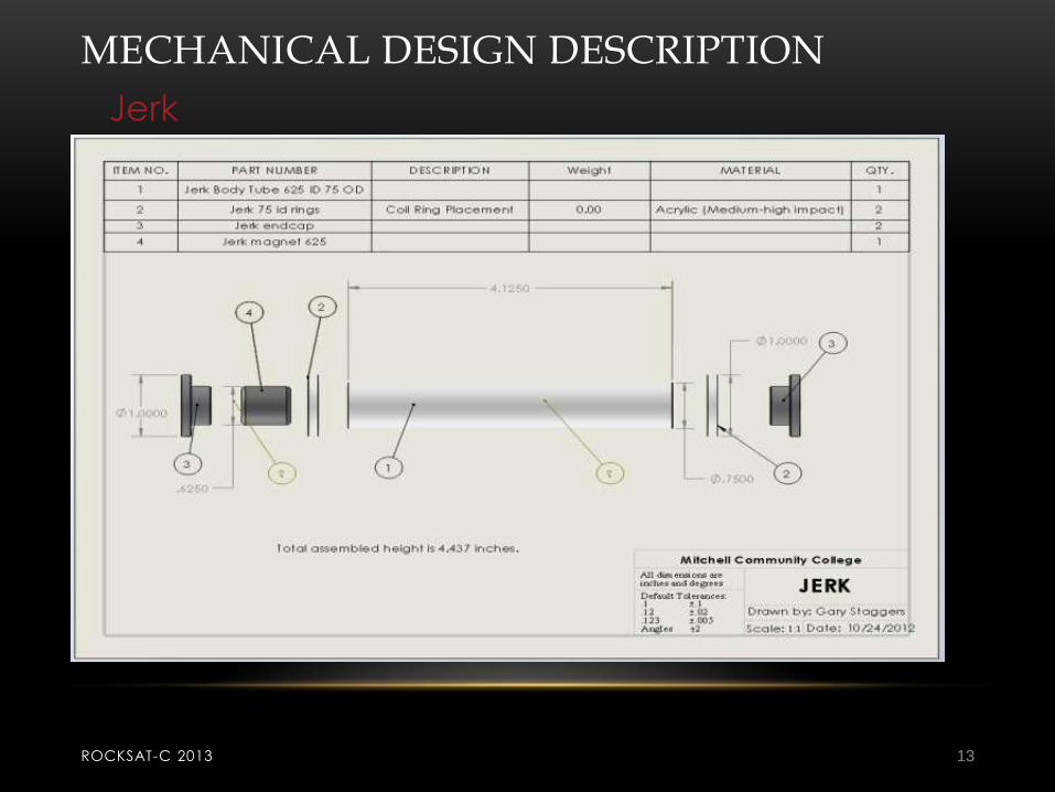
MECHANICAL DESIGN DESCRIPTION
Jerk
ROCKSAT-C 2013 13
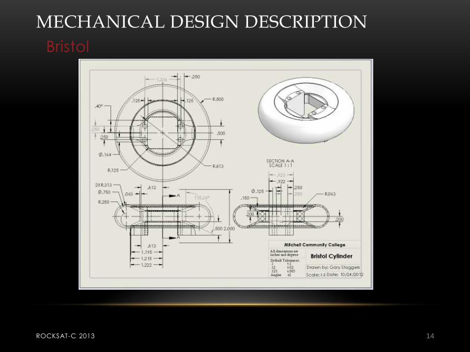
MECHANICAL DESIGN DESCRIPTION
Bristol
ROCKSAT-C 2013 14
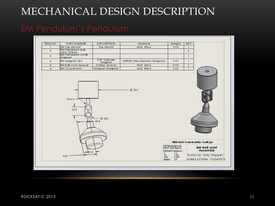
MECHANICAL DESIGN DESCRIPTION
EM Pendulum’s Pendulum
ROCKSAT-C 2013 15

MECHANICAL DESIGN DESCRIPTION
ROCKSAT-C 2013 16
EM Pendulum’s Base
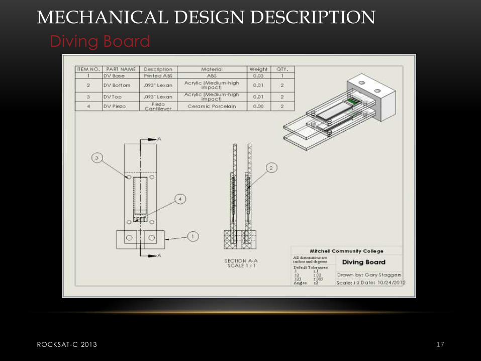
MECHANICAL DESIGN DESCRIPTION
Diving Board
ROCKSAT-C 2013 17

MECHANICAL DESIGN DESCRIPTION
Aubade
ROCKSAT-C 2013 18

Electrical Description
Presented By: Tony Briceno
PEGASIS II
ROCKSAT-C 2013 19
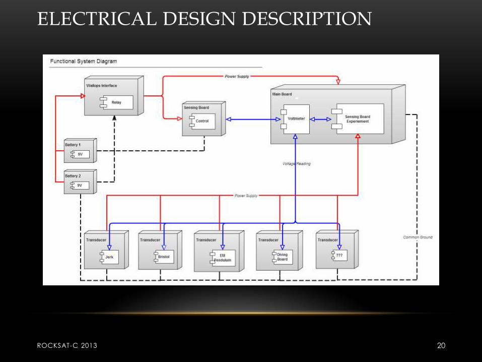
ELECTRICAL DESIGN DESCRIPTION
ROCKSAT-C 2013 20
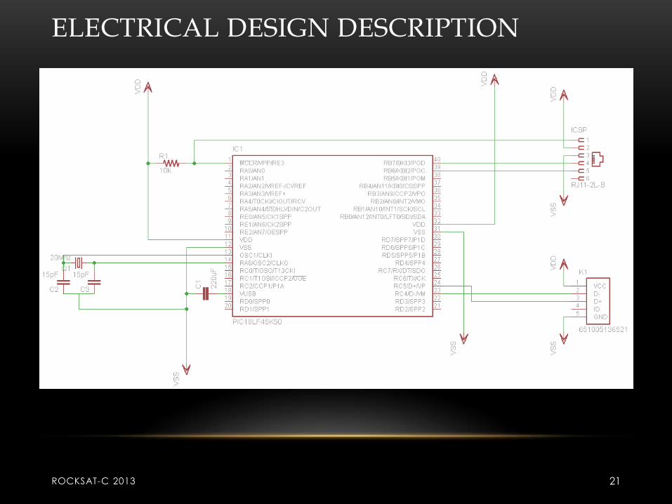
ELECTRICAL DESIGN DESCRIPTION
ROCKSAT-C 2013 21

ELECTRICAL DESIGN DESCRIPTION
To be Completed
• Design and test a z-axis g-switch to latch power on after lift-off
• Test battery configurations for longevity and current supply
• Research availability of surface mount versions of components from
2012 mission
Changes
• Main processor and both sensing boards will contained on one circuit
board
• Low power processors were chosen for testing. No negative effects are
indicated from datasheets on processor performance. The lower
voltages will increase battery performance.
ROCKSAT-C 2013 22

ELECTRICAL DESIGN DESCRIPTION
Activation
• Our payload will use command line activation
• A z-axis g-switch will latch the power supply after lift off.
ROCKSAT-C 2013 23

ELECTRICAL DESIGN DESCRIPTION
Plan of attack deadlines
• 12/14 - Test different processors to confirm final selection
• 1/11 – Confirm components for power supply and basic processor operation
• 1/18 – Basic coil design testing should be done to determine possible voltage maximums
• 1/25 – Confirm components for USB operation to comply with USB 2.0 standards
• 2/8 – Build proto-board to test revision 1 of software code on
• 2/15 – Final coil designs should be determined for each transducer
• 2/22 – Finalize revision 1 of board design and expand to include sensing boards
• 2/29 – Finalize voltage regulation of transducers to keep from damaging processors during A/D conversion.

ELECTRICAL DESIGN DESCRIPTION
To be considered
• Voltage regulators need to be chosen for each processor, 2 in total
• At least 3 revisions will be needed before a flight ready board will be
available
• 2 prototypes will be built in house for testing. Revisions 1 and 2.
• Subsequent revisions will be designed for manufacture from a board
house.
• PCB to transducer wiring harness connectors and wiring still needs to be
determined
• Smaller more efficient solar cells need to be obtained to replace the
current Aubade design

Software Description
Presented By: Tony Briceno
PEGASIS II
ROCKSAT-C 2013 26

SOFTWARE DESIGN DESCRIPTION
Purpose
• Control the measuring of power developed by transducers and used by
sensing boards
• Store the information in a readable form.
I/O’s
• Analog input for transducers and sensing boards (ADC)
• Digital output for indicator LED
ROCKSAT-C 2013 27

SOFTWARE DESIGN DESCRIPTION
To be Completed
• Processor settings need to be confirmed and tested for proper
operation.
• ADCloop – Settings need to be checked and code tested to check
proper operation.
• USB settings need to be confirmed. Preferably compliant with USB 2.0
standards. Interface and code needs to be checked for proper
operation.
ROCKSAT-C 2013 28
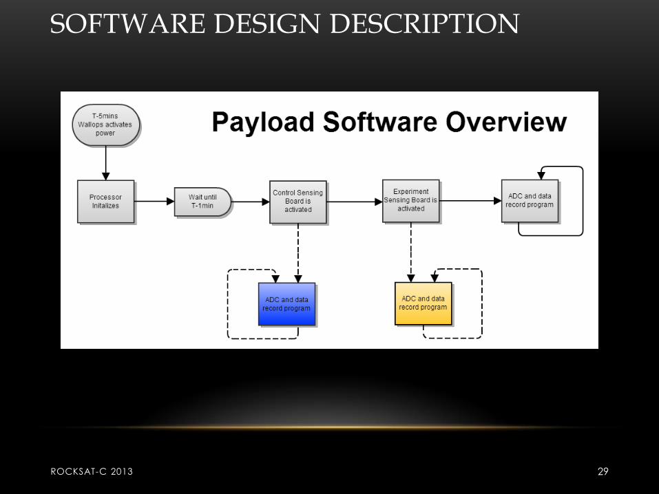
SOFTWARE DESIGN DESCRIPTION
ROCKSAT-C 2013 29

SOFTWARE DESIGN DESCRIPTION
ROCKSAT-C 2013 30
SOFTWARE DESIGN DESCRIPTION
ROCKSAT-C 2013 31
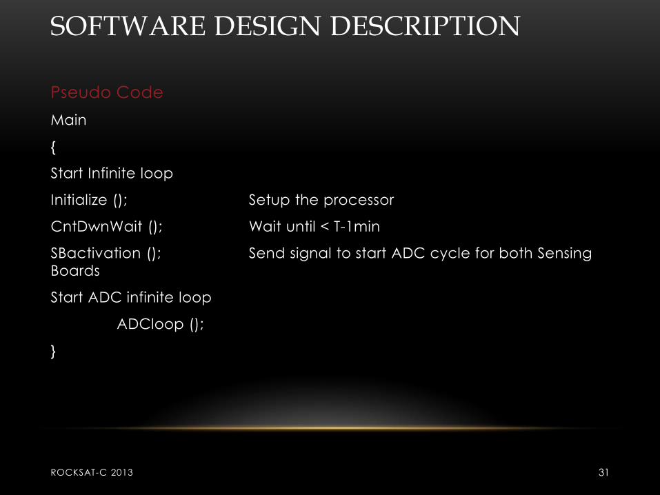
Pseudo Code
Main
{
Start Infinite loop
Initialize (); Setup the processor
CntDwnWait (); Wait until < T-1min
SBactivation (); Send signal to start ADC cycle for both Sensing
Boards
Start ADC infinite loop
ADCloop ();
}

SOFTWARE DESIGN DESCRIPTION
ROCKSAT-C 2013 32
Pseudo Code
Initialize
{
Select clock settings
Select Communication ports and settings
Select analog ins and digital outs
Set interrupts
}
CtnDownWait
{
Loop for Aprox 2 min
}
SOFTWARE DESIGN DESCRIPTION
ROCKSAT-C 2013 33
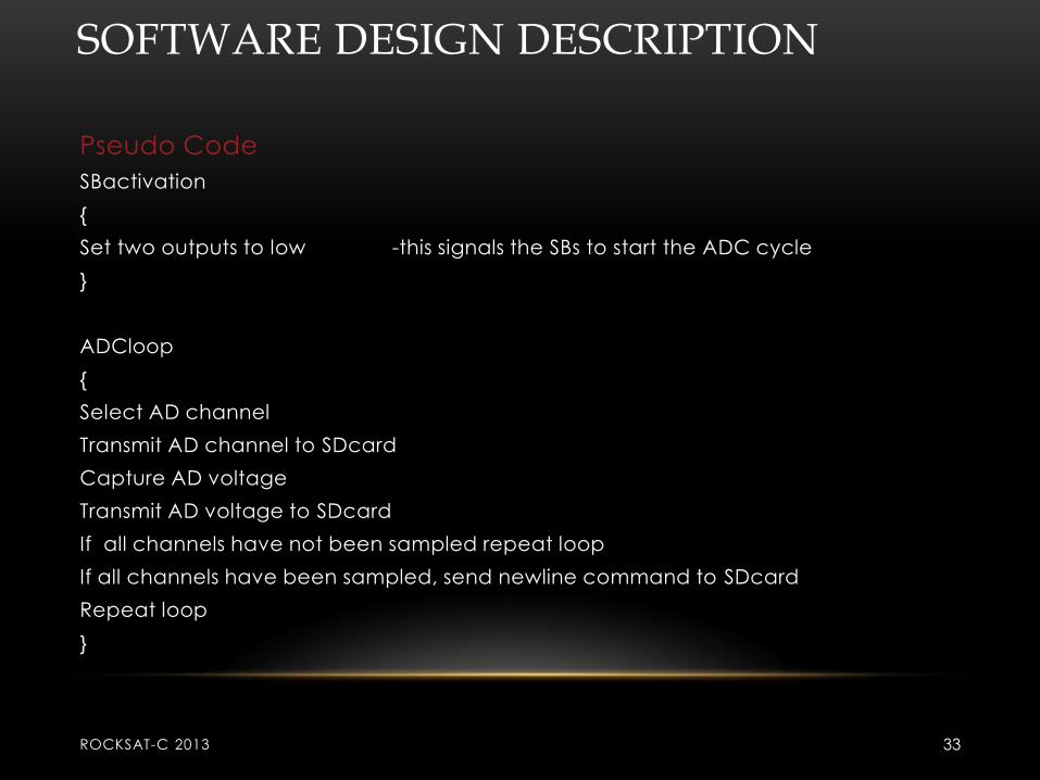
Pseudo Code
SBactivation
{
Set two outputs to low -this signals the SBs to start the ADC cycle
}
ADCloop
{
Select AD channel
Transmit AD channel to SDcard
Capture AD voltage
Transmit AD voltage to SDcard
If all channels have not been sampled repeat loop
If all channels have been sampled, send newline command to SDcard
Repeat loop
}

SOFTWARE DESIGN DESCRIPTION
Plan of attack deadlines
• 12/14 - Test different processors to confirm final selection
• 12/21 – Confirm working code for processor initialization is working
• Holiday break – use to time research USB 2.0 standards
• 1/11 – Confirm A/D settings and ADCloop code functions properly
• 1/18 – Finalize and test activation sequence for sensing boards
• 1/25– Confirm USB settings and basic interface with computer
• 2/1– Improve interface with computer to allow streaming data when
connected
• 2/8 – Test all portions of code working as one
• 2/15 – Finalize revision 1 of software code
ROCKSAT-C 2013 34

Prototyping/Analysis
Presented By: Colin Robinson
PEGASIS II
ROCKSAT-C 2013 35
PROTOTYPING/ANALYSIS
We have yet to begin testing. We have been designing and
building our own equipment to test our components for each
subsystem. We have also begun breaking down PEGASIS l parts to
test against new components.
ROCKSAT-C 2013 36

PROTOTYPING/ANALYSIS
We are in the entry stages of prototyping and will have it complete by the beginning of next semester.
ROCKSAT-C 2013 37

MASS BUDGET
PEGASIS Mass Budget
Subsystem Total Mass (lb)
BSTL .26 (by hand)
EMPD .08
DVBD .18 (by hand)
JERK .35
CRSH .11
ABDE .02
ELVS .01
Total 1.01
Over/Under (including electrical &
hardware)
0.78

ELECTRICAL DESIGN DESCRIPTION
Power Budget
Subsystem Voltage(V) Current(A) Time On(Hrs) Amp-Hours
Main 3.3 0.15 1.25 0.1875
SBCon 3.3 0.15 1.25 0.1875
SBExp 0 0 0 0
Total(A*Hrs) 0.375
• Preliminary battery pack designs have us at approximately 7.5V and
9000mAh
• Maximum current draw of the processors combined is approximately
400mA. Even if the batteries drain twice as fast as rated, there will still be
sufficient current/voltage to power the devices for longer than planned.

Manufacturing Plan
Presented By: Mason Young
PEGASIS II
ROCKSAT-C 2013 40
MANUFACTURING PLAN
Need to be manufactured:
• Makrolon Plates
• Mounting Board for Electronics
• Mounting device to hold battery
ROCKSAT-C 2013 41

MANUFACTURING PLAN
Still need to be procured:
– All items will be manufactured in house
– Research on new magnets and possible
procurement
ROCKSAT-C 2013 42
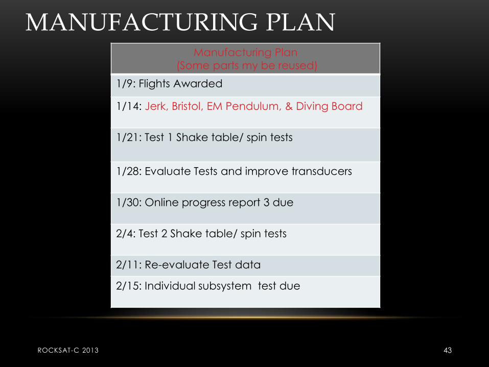
MANUFACTURING PLAN Manufacturing Plan
(Some parts my be reused)
1/9: Flights Awarded
1/14: Jerk, Bristol, EM Pendulum, & Diving Board
1/21: Test 1 Shake table/ spin tests
1/28: Evaluate Tests and improve transducers
1/30: Online progress report 3 due
2/4: Test 2 Shake table/ spin tests
2/11: Re-evaluate Test data
2/15: Individual subsystem test due
ROCKSAT-C 2013 43
MANUFACTURING PLAN
Electrical elements
Need to be manufactured:
• 2 prototypes
• Proto-board
ROCKSAT-C 2013 44

Testing Plan
Presented By: Nathan Keller
PEGASIS II
ROCKSAT-C 2013 45
TESTING PLAN
• Tests will verify payload meets user guide
requirements and functionality under high G-forces,
strong vibrational forces, and heat
• Similar to last year a mock up payload will undergo
test flights and shake table testing
• Additional tests have been included to test
performance under heat and magnetic
interference
ROCKSAT-C 2013 46

TESTING PLAN
• Functionality of the payload and individual
components shall be tested through test flights and
shake table testing
• Measurement of G-forces and vibrational forces,
inspection of components, and results from
collected data will be used to verify functionality
ROCKSAT-C 2013 47

MECHANICAL TESTING PLAN
• Measurements of mass and volume will
verify payload remains within user guide
requirements
• Individual components will be tested on
fabrication is completed, full canister tests
will begin once all individual components
have been tested
ROCKSAT-C 2013 48

ELECTRICAL TESTING PLAN
• Electrical system will be tested to minimize
effects from magnetic interference, ensure
heat durability, and verify connections
between components can withstand flight
conditions
• Placement tests of components will be used
to minimize magnetic interference
ROCKSAT-C 2013 49

ELECTRICAL TESTING PLAN
• Connections will be tested during test flights
and shake table testing
• Payload will be tested for functionality under
heated conditions to verify durability.
• Electrical tests will begin once electrical
components are acquired
ROCKSAT-C 2013 50

SOFTWARE TESTING PLAN
It will be necessary to develop code to
measure output from transducers and
sensing boards during testing
Software testing will begin once A/d
converter is aquired
ROCKSAT-C 2013 51

INTEGRATION TESTING PLAN
Integration of components to payload (fit-
checks) will be tested once component
construction is completed
Tests will be preformed at Mitchell by
mechanical team
ROCKSAT-C 2013 52

Electrical connections to components will
be tested once components are
completed
Tests will be preformed at Mitchell by
electrical team
Integration of payload into canister tests will
begin once canister arrives
INTEGRATION TESTING PLAN
ROCKSAT-C 2013 53

Tests will be preformed by mechanical
team to confirm that components align
correctly with optical port
Integration with partner team will be
preformed at Wallops to ensure
compatibility between payloads and the
canister
INTEGRATION TESTING PLAN
ROCKSAT-C 2013 54

INTEGRATION TESTING PLAN
Tests will be preformed by designated
members from both teams
ROCKSAT-C 2013 55

Risks
Presented By: Nathan Keller
PEGASIS II
ROCKSAT-C 2013 56

RISKS
RockSat-C 2013 57
Highly Unlikely Unlikely Possible Likely
Negligible
Marginal PMF
Critical WMF MVF EGF
EWH PHD
Catastrophic RMF EGF - Damage to electronic components due to G-forces
EWH - Damage to external wiring harness PHD - Processor damage due to heat PMF - PCB mounting failure MVF - Mechanical mounting failure due to vibration
WMF - Wallops mechanical failure RMF - Rocket motor failure

RISKS
BigBiggest risks at PDR were:
Damage to external wiring harness
Processor damage dues to heat
Damage to electrical components due to G-
forces
These risks have been mitigated through selection
of parts and design of system, this will be verified through testing

RISKS
Highly Unlikely Unlikely Possible Likely
Negligible
Marginal PMF
Critical
WMF MVF EGF
EWH PHD
Catastrophic RMF EGF - Damage to electronic components due to G-forces
EWH - Damage to external wiring harness PHD - Processor damage due to heat PMF - PCB mounting failure MVF - Mechanical mounting failure due to vibration
WMF - Wallops mechanical failure RMF - Rocket motor failure
RISKS
Biggest risks presently are:
Damage to external wiring harness
Processor damage dues to heat
PCB mounting failure
Through testing of these components we plan to find possible flaws in design that can be addressed to mitigate risks
Rocket motor failure will have to be an accepted risk

User Guide Compliance
Presented By: Patrick Mencias-Lewis
PEGASIS II
ROCKSAT-C 2013 61

USER GUIDE COMPLIANCE
• The mass of the payload, including canister, is …( See Colin’s Slide)
• The center of mass of our canister is within the 1”x1”x1” envelope requirement, verified using SolidWorks.
• The payload control sensing board will be powered by a ______battery (ask Tony/See his Slides).
• Design of payload will utilize a 1.SYS.1 activation to ensure there is no
open connection of power from the transducers.
ROCKSAT-C 2013 62

SHARED CAN LOGISTICS
• We plan to share half a canister with New Jersey
• To communicate we plan to use Skype and email to share our designs
• To combine the two payload sections between us we plan to join using standoffs.
ROCKSAT-C 2013 63

Project Management Plan
Presented By: Catherine Maynard
PEGASIS II
ROCKSAT-C 2013 64

SCHEDULE
• Event Date
Testing Report Presentation Due 4/26/2013
Test report Teleconference 4/26/2013
Meeting 5/6/2013
Weekly Teleconference 4 5/8/2013
Meeting 5/13/2013
Weekly Teleconference 5 5/15/2013
Meeting 5/20/2013
Weekly Teleconference 6 5/29/2013
Weekly Teleconference 7 5/29/2013
Launch Review Presentation 6/3/2013
Travel To Wallops 6/12/2013
Visual Inspections at and Integration at Wallops 6/13/2013
Presentation to Next Year’s RockSat Project 6/19/2013
Launch Day 6/20/2013
Event Date
CDR Teleconference 12/5/2012
Meeting 12/10/2012
Meeting 12/17/2012
Meeting 1/7/2013
Final Down Select 1/9/2013
Meeting 1/14/2013
Meeting 1/21/2013
First Payment Due 1/25/2013
Online Progress Report 1 Due 1/25/2013
Meeting 1/29/2013
Payload Subsystem Integration,
Teleconference for ISTR 4/1/2013
Final Payment Due 4/5/2013
Meeting 4/8/2013
RockSat Canister Sent to Customers 4/15/2013
Meeting 4/22/2013
BU
DG
ET
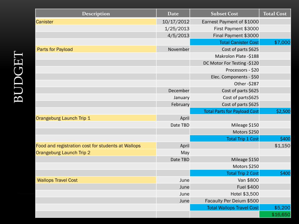
Description Date Subset Cost Total Cost
Canister 10/17/2012 Earnest Payment of $1000
1/25/2013 First Payment $3000
4/5/2013 Final Payment $3000
Total Canister Cost $7,000
Parts for Payload November Cost of parts $625
Makrolon Plate -$188
DC Motor For Testing -$120
Processors - $20
Elec. Components - $50
Other -$287
December Cost of parts $625
January Cost of parts$625
February Cost of parts $625
Total Parts for Payload Cost $2,500
Orangeburg Launch Trip 1 April
Date TBD Mileage $150
Motors $250
Total Trip 1 Cost $400
Food and registration cost for students at Wallops April $1,150
Orangeburg Launch Trip 2 May
Date TBD Mileage $150
Motors $250
Total Trip 2 Cost $400
Wallops Travel Cost June Van $800
June Fuel $400
June Hotel $3,500
June Facaulty Per Deium $500
Total Wallops Travel Cost $5,200
$16,650
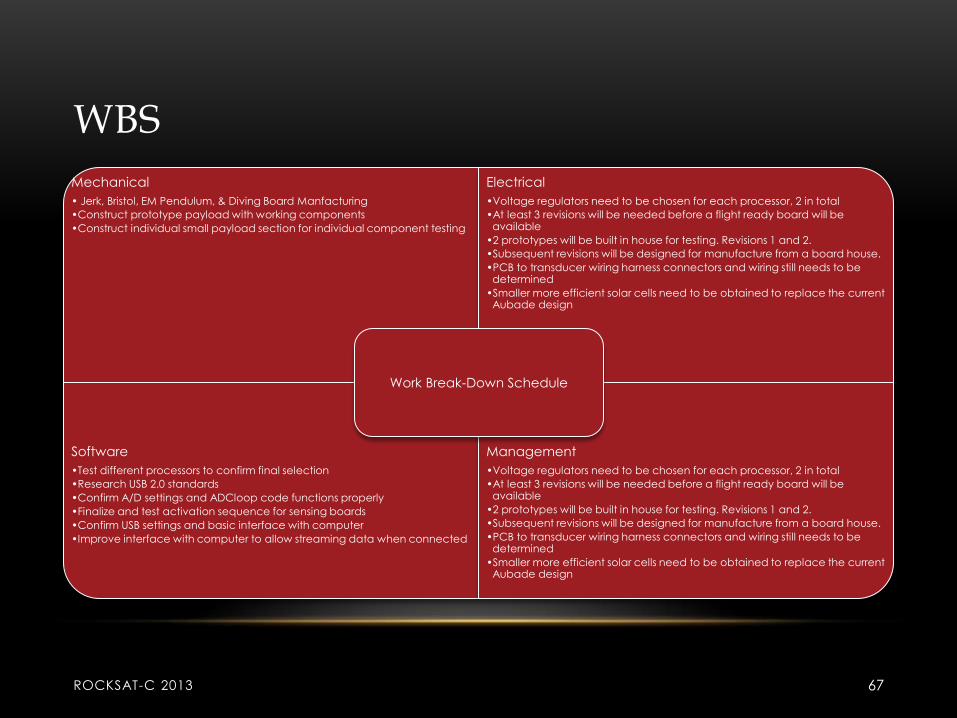
WBS
Mechanical
• Jerk, Bristol, EM Pendulum, & Diving Board Manfacturing
•Construct prototype payload with working components
•Construct individual small payload section for individual component testing
Electrical
•Voltage regulators need to be chosen for each processor, 2 in total
•At least 3 revisions will be needed before a flight ready board will be available
•2 prototypes will be built in house for testing. Revisions 1 and 2.
•Subsequent revisions will be designed for manufacture from a board house.
•PCB to transducer wiring harness connectors and wiring still needs to be determined
•Smaller more efficient solar cells need to be obtained to replace the current Aubade design
Software
•Test different processors to confirm final selection
•Research USB 2.0 standards
•Confirm A/D settings and ADCloop code functions properly
•Finalize and test activation sequence for sensing boards
•Confirm USB settings and basic interface with computer
•Improve interface with computer to allow streaming data when connected
Management
•Voltage regulators need to be chosen for each processor, 2 in total
•At least 3 revisions will be needed before a flight ready board will be available
•2 prototypes will be built in house for testing. Revisions 1 and 2.
•Subsequent revisions will be designed for manufacture from a board house.
•PCB to transducer wiring harness connectors and wiring still needs to be determined
•Smaller more efficient solar cells need to be obtained to replace the current Aubade design
Work Break-Down Schedule
ROCKSAT-C 2013 67

PROJECT SUMMARY
• Remaining Issues: None.
• Areas of concern:
• 1.SYS.1 integration with systems that are always generating
electricity.
• Plan of Action
• After the final down selection we will begin construction of the Payload and testing of its components.
• Before winter break:
• BeginsSchematical manufacturing planning so after the final down selection we can begin manufacturing based on the plans constructed.
ROCKSAT-C 2013 68

Conclusion
Presented By: Catherine Maynard
PEGASIS II
ROCKSAT-C 2013 69