Embed Size (px)
Citation preview
CONCEPTUAL DESIGN OF TWO-PLATE INJECTION MOLD FOR UMP'S KEYCHAIN
AZHAR BIN YUSOP
A report submitted in partial fulfillment of the requirement for the award of degree of Mechanical Engineering
Faculty of Mechanical Engineering Universiti Malaysia Pahang
MAY 2008
PERPUSTAKAAN UNIVEFST MALAYSIA PA14ANC3
No. Peroehan No. Panggian
03?955 Tarikh
0 2 JUL 2009rx
ABSTRACT
UTvIP's keychain is a small product made from plastic same as UMP
(University Malaysia Pahang) logo. Demand on plastic product in this country is
very tremendous because plastic product has better in quality, design and appearance
than any material product. To produce better quality of plastic product, it needs to
have some processes and most important is initially in design stages. High quality
plastic product can be produced using injection molding process that required good
design of mold. In design the plastic mold the most important thing is get the suitable
size runner and gate system. This project is using Moldflow Mold Adviser software
in order to get achieve optimum size runner and gate system for two-plate injection
mold for UMP's keychain
ABSTRAK
Rantai kunci UMP ialah satu produk kecil yang di perbuat dari plastik
berbentuk logo (iMP (Universiti Malaysia Pahang). Pada dasarnya permintaan
produk plastik di negara mi sangat menggalakkan kerana produk plastik adalah
setanding dengan produk yang dihasilkan dari bahan yang lain rnalah produk plastik
juga lebih cantik dari segi rupa bentuk serta bennutu. Maka dengan itu untuk
menghasilkan produk .plastik yang bermutu, produk plastik yang ingin dihasilkan
perlu melalui beberapa proses yang sepatutnya terutamanya yang penting sekali ialah
pada proses permulaan yang melibatkan proses reka bentuk. Produk plastik yang
baik dapat dihasilkan dengan menggunakan proses injection molding yang
memerlukan reka bentuk acuan yang baik. Untuk mereka bentuk acuan plastic, yang
paling penting adalah mendapatkan ukuran runner dan gate sistem yang sesuai.
Kajian ml menggunakan perisian Moldflow Mold Adviser untuk mendapatkan
ukuran runner dan gate sistem yang optima untuk 2-plate suntikan acuan untuk
rantai kunci UMP.
vi'
TABLE OF CONTENTS
CHAPTER
TITLE PAGE
TITLE PAGE
SUPERVISOR DECLARATION
STUDENT DECLARATION
DEDICATION iv
ACKNOWLEDGEMENTS v
ABSTRACT vi
ABSTRAK vii
TABLE OF CONTENTS viii
LIST OF TABLES xii
LIST OF FIGURES xiii
LIST OF SYMBOLS xvi
LIST OF APPENDICES xvii
1
INTRODUCTION 1
1.1 Project Background 1
1.2 Problem Statement 2
1.3 Project Objective 2
1.4 Project Scope. 2
2 LflERATURE REVIEW 3
2.1 Introduction 3
2.2 Injection Molding 3
2.2.1 Raw Material 4
VII'
2.2.2 Injection Molding Cycle and Process 4
2.3 Part Design Guideline for Injection Molded Plastic 5
Part
2.3.1 Wall Thickness 5
2.3.2 Corner, Fillet and Radii 6
2.3.3 Rib 7
2.3.4 Bosses and Gussets 8
2.3.5 Taper and Draft Angles 9
2.4 Injection Mold Design. 9
2.4.1 Type of Injection Mold 10
2.4.2 Standard Mold Assembly 10
2.4.2.1 Mold Part Name and Functions 11
2.4.3 Cavity and Core 13
2.4.3.1 Construction of Cavity section. 14
2.4.4 Passageway of Molten Resin 15
2.4.4.1 Sprue 15
2.4.4.2 Runner 16
2.4.4.3 Gate Design 17
2.4.5 MoldTemperature Control 19
2.4.6 Venting 19
2.5 Mold Design Procedure 20
2.5.1 Decision of Number of Cavity 20
2.5.2 Decision of Arrangement of Cavities 20
2.5.3 Decision of parting line (P.L) 21
2.5.4 Decision of Under Cut Treating Method 21
2.5.5 Decision of ejecting method. 22
2.5.6 Decision of Cavity and Core Construction 22
2.5.7 Decision of Runner System 23
2.5.8 Decision type of gate 23
2.5.9 Decision of Temperature Control Method 23
2.5. 10 Decision of Cavity and Core Fixing Method 23
2.5.11 Decision of Mold Material and Surface 24
Treating Method
IM
2.5.12 Decision of Mold Dimension 24
2.5.13 Plotting of layout drawing 24
2.6 Mold flow software 25
2.6.1 Moldflow mold advsor(MPA) 26
2.6.1.1 Analysis Capabilities 26
2.6.1.2 Advantages of Moldfiow Analysis 27
3
METHODOLOGY 29
3.1 Introduction 29
3.2 Drawing of Product 31
3.3 Material Selection 32
3.4 Analysis Sequences 32
3.4.1 Best Gate Analysis 33
3.4.2 Molding Window 33
3.4.3 Sink Mark analysis 33
3.4.4 Runner balance analysis. 33
3.4.5 Fill and Cooling analysis 34
3.5 Analysis by using Moidflow Software(MPA 8.1) 34
3.6 Design the Injection Mold of (JMP keychain 34
4 RESULTS AND DISCUSSION 37
4.1 Introduction 37
4.2 Analysis of Best Gate Location 37
4.3 Result Analysis on First Gate Location 38
4.3.1 Molding Window Analysis 39
4.3.2 Sink Mark Analysis 40
4.3.3 Runner Balance Analysis 41
• 4.3.4 Plastic Filling Analysis 43
4.3.4.1 Confidence of Fill 43
4.3.4.2 Cooling Analysis 48
4.4 Result Analysis on Second Gate Location 50
x
4.4.1 Molding Window Analysis 50
4.4.2 Sink Mark Analysis 51
4.4.3 Runner Balance Analysis 52
4.4.4 Plastic Filling Analysis 54
4.4.4.1 Confidence of Fill 54
4.4.4.2 Cooling Analysis 59
4.5 Discussion 60
4.5.1 Analysis of Gate Location 60
4.5.2 Molding Window Analysis 61
4.5.3 Sink Mark Analysis. 61
4.5.4 Runner Balanced Analysis 61
4.5.5 Filling Analysis 62
4.5.5.1 Fill Time 62
4.5.5.2 Confidence of Fill 63
4.5.5.3 Flow Front Temperature 63
4.5.5.4 Skin Orientation 65
4.5.5.5 Weld Line Prediction 65
4.5.5.6 Air Trap Estimated 66
4.5.5.7 Cooling Analysis 66
4.5.6 Conclusion between First and Second Gate 66
Location
4.6 Design of Two-Plate Injection Mold for UMP 67
Keychain
5 CONCLUSION AND RECOMMENDATION 71
5.1 Conclusion 71
5.2 Recommendation 72
REFERENCES 73
xi
APPENDICES 74-82
LIST OF TABLES
TABLE NO. TITLE PAGE
2.1 Type of runner layout 16
2.2 Types of gate 17
3.1 Typical Injection Molding Conditions for ABS material 32
4.1 The changes advised for first gate location 42
4.2 Risk of the part filling base on color 44
4.3 Summary result filling analysis at the first gate location 48
4.4 The changes advised for second gate location 53
4.5 Risk of the part filling base on color 55
4.6 Summary result filling analysis at the second gate location 58
4.7 Runner balance advisor for two difference gate location 62
4.8 Comparison of result analysis result for first and second 67 gate location
xli
LIST OF FIGURES
FIGURE NO. TITLE PAGE
2.1 Recommended change at the intersection of think/thin 6 region
2.2 Proper designs of corners in a plastic part 7
2.3 Guideline for design of rib respect to wall thickness 7
2.4 Free standing boss with four gussets 8
2.5 Free standing boss with two gussets 8
2.6 Draft on the inside and outside surface of part should be 9 equal and parallel
2.7 Standard mold ii
2.8 Cavity and core 13
2.9 Mold without core 13
2.10 Direct profile types 14
2.11 Insert type 15
2.12 Guideline for design of sprue 15
2.13 Cross-section design of runner 16
2.14 Recommended depth and pitch of mold cooling channel 19
3.1 Flow Chart 30
3.2 UMP keychain.(front view) 31
3.3 Ump keychain(side view) 31
xli'
3.4 Ump keychain (Top view) 31
3.5 Direct profile types. 35
3.6 li-Type runner layout. 35
3.7 Parting line 36
4.1 Analysis of the best gate locations for the Ump's 38 keychain
4.2 Analysis of the best gate locations for the Ump's 38 keychain
4.3 First gate location 39
4.4 Equivalent injection time and melting temperature 40
4.5 Sink Mark estimated for the UMP keychain by using edge 41 gate
4.6 Sprue (A B), Runner (C D) and Gate (E) using for 42 analysis at first gate location
4.7 Fill time by using the original design of sprue runner and 42 gate
4.8 Fill time by change the dimension of runner and gate as 43 per moldflow advised
4.9 Confidence of filling at the first gate location 44
4.10 Confident of fill after change mold and melt temperature 45
4.11 Temperature of flow front 45
4.12 Orientation of skin result from first gate location 46
4.13 Weld line prediction 47
4.14 Air trap estimation by using edge gate in two-plate mold 47
4.15 Design of cooling system. 48
4.16 Surface temperature variance by using edge gate at first 49 gate Location
4.17 Cooling time variance by using edge gate at first gate 49 location
4.18 The cooling quality by using edge gate at first location. 50
4.19 Second gate location 50
4.20 Equivalent injection time and melting temperature. 51
4.21 Sink Mark estimated for the second gate location analysis 52
4.22 Gating system for second gate location analysis 53
4.23 Fill time from original gating system for second gate 53 location analysis
4.24 Fill time by change the dimension of runner and gate as 54 per moldflow advised
4.25 Confidence of filling at the second gate location 55
4.26 Flow front temperature by using edge gate at second gate 56 location
4.27 Skin orientation on the liMP keychain 56
4.28 Weld line prediction by using edge gate at second gate 57 location
4.29 Air trap estimation by using edge gate at second gate 58 location
4.30 Temperature Variance by using edge gate at second gate 59 location
4.31 Cooling Time Variance by using edge gate at second gate 59 location
4.32 Cooling Quality by using edge gate for second gate 60 location
4.33 Flow front temperature result displays 64
4.34 Complete assembly of two-plate mold 68
4.35 Fixed half mold (Cavity side) side view of two-plate mold 68
4.36 Moving half mold (Core side) side view of two plate 69 mold
4.37 Plan (Top) view of complete assembly two-plate mold 69
4.38 Side view of complete assembly two-plate mold 70
LIST OF SYMBOLS
ABS - Acrylonitrile-Butadiene-Styrene
PA - Polyamide
PC - Polycarbonate
PP - Polypropylene
PS - Polystyrene
Pit - Parting line
HREG - Hot runner edge gating
TG - Tunnel gating
EG - Edge gating
- Depth of recess
t - Thickness
D - Diameter
11 - Height
xvi
LIST OF APPENDICES
APPENDIX TITLE PAGE
A Drawing of cavity plate 74
B Drawing of core plate 75
C Drawing of locating ring 76
D Drawing of sprue bush 77
E Drawing of guide pin 78
F Drawing of pin (ejector plate) 79
Ci Drawing of spacer block 80
H Drawing of ejector pin 81
1 Drawing of ejector plate 82
xvii
CHAPTER 1
INTRODUCTION
1.1 Project Background
Injection molding nowadays have been one of the most important industry in
the world. By using this method, the production became faster and more productive.
The developing of injection molding becomes a competition from day to day. This
process now integrated with computer control make the production better in. quality
and better quantity.
In designing the mold for injection molding, the accuracy in making mold
very important in order to reduce cost and also to make sure that the mold broke
easily. Before this, the mold designer used manual analysis to the mold. But now,
there is software that can simulate the analysis of the mold that wants to develop.
Clearly, more and more manufacturers are using computational and analytical
techniques to reduced design time and cost while significantly improving yield and
quality. By using plastics flow simulation products, the determination of
manufacturability of part in the early design stages and avoids potential downstream
problems which can lead to production delays and cost overruns.
Simulation software allows to do some trouble shooting very easily. Some of
the materials that were use are very expensive. Therefore,, less time on the production
floor working through a problem saves labor and material costs. By using software,
designers been able to run simulations and locate and eliminate unsightly nit lines.
2
Problems that can be avoided by performing flow analysis early in the design
stages are air traps, warpage, sink marks and voids, shrinkage, weld lines and meld
lines.
1.2 Problem Statement
The problems statement for this project is:
i. Normally, more than three times mold testing required to balancing the
material flow into the part especially for multi-cavities and family molds.
ii. improper gate size, gate location and runner size will caused the long time
for mold testing to get the desired final appearance of the product.
1.3 Project Objective
The objective of the project is to analysis material flow for injection molding
process in order to get the suitable runner and gate system and design the two-plate
injection mold for UMP keychain.
1.4 Project Scope
In order to achieve the objective, the project scopes must include:
i. Literature review on injection molding mold.
ii. Design the UMP keychain using Solid works.
iii. Analysis the material flow using Mould flow software in order to select
the suitable runner and gate system.
iv. Design the two-plate injection mold for UMP keychain.
v. Injection mold die is from standard die
CHAPTER 2
LITERATURE REVIEW
2.1 Introduction
The best way is the molds and parts designer must have a good knowledge on
the basic of injection molding process. It will help them to design for manufacturer
and not just a design which is very nice but can't be manufactured. In this chapter,
we will look at the basic theory of plastic injection molding including type of
material, product design, mold design and process.
2.2 Injection Molding
Injection Molding is the process of forcing melted plastic in to a mold cavity.
Injection molding is used for processing thermoplastics, thermosets, and elastomers.
This is a high-rate production process and permits good dimensional control.
Injection molding is a versatile process capable of producing complex. shapes with
good dimensional accuracy and at high production rate. [5]
The advantages of injection molding are high production rates, high
tolerances are repeatable, wide range of material can be used, low labor costs,
minimal scrap losses, little need to finish parts after molding and design flexibility.
4
12.1 Raw Materials
Most raw materials can be used. The resin is in pellets before processing. The
examples of the material are Acrylonitrile-Butadiene-Styrene (ABS), Polyamide or
Nylon (PA), Polycarbonate (PC), Polypropylene (PP), and Polystyrene (PS).[3]
2.2.2 Injection Molding Cycle and Process
The basic injection cycle is as follows: Mold close - injection carriage
forward * injects plastic - metering - carriage retracts - mold open - eject part.
The molds are closed shut, by hydraulics or electric, and the heated plastic is
forced by the pressure of the injection screw to take the shape of the mold. Some
machines are run by electric motors instead of hydraulics or a combination of both.
The water-cooling channels then assist in cooling the mold and the heated plastic
solidifies into the part. Improper cooling can result in distorted molding or one that is
burnt. The cycle is completed when the mold opens and the part is ejected with the
assistance of ejector pins within the mold.
The resin, or raw material for injection molding, is usually in pellet or granule
form, and is melted by heat and shearing forces shortly before being injected into the
mold. Resin pellets are poured into the feed hopper, a large open bottomed container,
which feeds the granules down to the screw. The screw is rotated by a motor, feeding
pellets up the screw's grooves. The depth of the screw flights decreases towards the
end of the screw nearest the mold, compressing the heated plastic. As the screw
rotates, the pellets are moved forward in the screw and they undergo extreme
pressure and friction which generates most of the heat needed to melt the pellets.
Heaters on either side of the screw assist in the heating and temperature control
during the melting process.
The channels through which the plastic flows toward the chamber will also
solidify, forming an attached frame. This frame is composed of the sprue, which is
the main channel from the reservoir of molten resin, parallel with the direction of
6
issues related to the wall but also impact to on manufacturability such as injection
pressure required fill, cooling time and influence on ejection from the mold. [2]
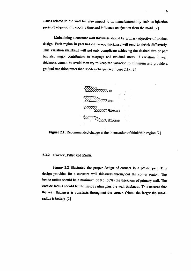
Maintaining a constant wall thickness should be primary objective of product
design. Each region in part has difference thickness will tend to shrink differently.
This variation shrinkage will not only complicate achieving the desired size of part
but also major contributors to warpage and residual stress. If variation in wall
thickness cannot be avoid then try to keep the variation to minimum and provide a
gradual transition ratter than sudden change (see figure 2.1). [2]
Figure 2.1: Recommended change at the intersection of think/thin region [2]
2.3.2 Corner, Fillet and Radii.
Figure 2.2 illustrated the proper design of corners in a plastic part. This
design provides for a constant wall thickness throughout the corner region. The
inside radius should be a minimum of 0.5 (50%) the thickness of primary wall. The
outside radius should be the inside radius plus the wall thickness. This ensures that
the wall thickness is constants throughout the corner. (Note: the larger the inside
radius is better) [2]
5
draw, and runners, which are perpendicular to the direction of draw, and are used to
convey molten resin to the gate, or point of injection. The sprue and runner system
can be cut or twisted off and recycled, sometimes being granulated next to the mold
machine. Some molds are designed so that the part is automatically stripped through
action of the mold. [10]
2.3 Part Design Guideline for Injection Molded Plastic Part
During part designing stage, the designers must consider whether the process
has been choice has a capability to meets the design requirement such as size of part,
shape, cosmetic appearance and tolerance.
The basic factors that should be considered during part designing are:
i. Use uniform wail thicknesses throughout the part. This will minimize
sinking, warping, residual stresses, and improve mold fill and cycle times.
ii. Use generous radius at all corners. The inside corner radius should be a
minimum of one material thickness.
iii. Use the least thickness compliant with the process, material, or product
design requirements. Using the least wall thickness for the process
ensures rapid cooling, short cycle times, and minimum shot weight. All
these result in the least possible parts cost.
iv. Design parts to facilitate easy withdrawal from the mold by providing
draft (taper) in the direction of mold opening or closing.
2.3.1 Wall Thickness
Plastic parts are generally designed around the use of relatively thin walls.
Unless the injection molded plastic part is produced with gas assist injection
molding, its walls are normally less than 5mm.When determining the thickness of the
primary wall one must consider not only the structural, functional and aesthetic
7
POOR POOR HIGH STRESS HIGH VOLUME
E= an
PDW
Figure 2.2:. Proper designs of corners in a plastic part [2]
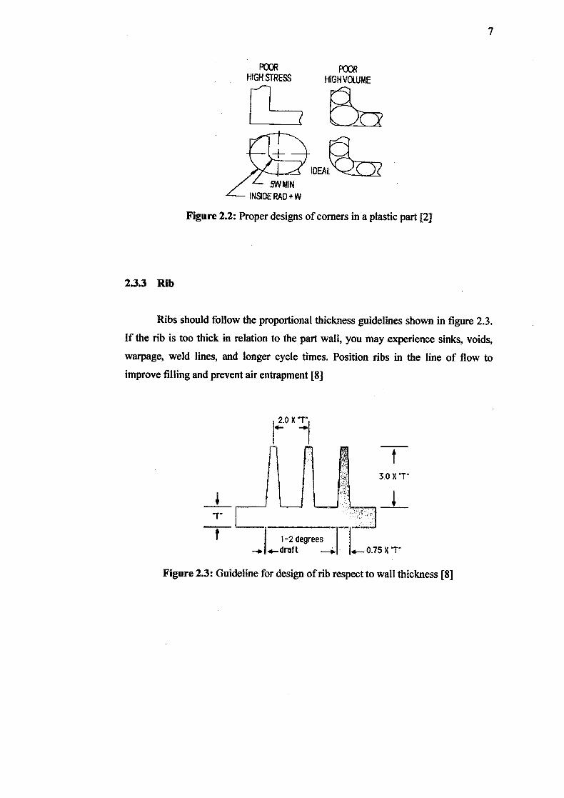
2.3.3 Rib
Ribs should follow the proportional thickness guidelines shown in figure 2.3.
If the rib is too thick in relation to the part wall, you may experience sinks, voids,
warpage, weld lines, and longer cycle times. Position ribs in the line of flow to
improve filling and prevent air entrapment [8]
2.0 X T
3ox.
t 1-2 degrees
--W 4_draft 0.75 X T
Figure 2.3: Guideline for design of rib respect to wall thickness [8]
Gussets 4 pieces
B
Gussets 2 pluses
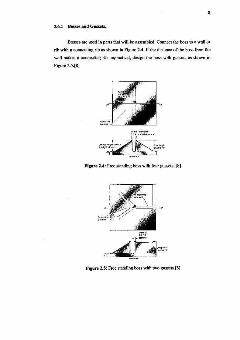
2.6.1 Bosses and Gussets.
Bosses are used in parts that will be assembled. Connect the boss to a wall or
rib with a connecting rib' as shown in Figure 2.4. If the distance of the boss from the
wall makes a connecting rib impractical, design the boss with gussets as shown in
Figure 2.5.[8]
overall diameter 3.0 0 Internel diameter
-t Gusset height 0.6-0.7 Boss height 0 height 01 boss I' of 3.0 Mr
Smhe -A
Figure 2.4: Free standing boss with four gussets. [8]
Draft of 05-10 degrees
r4<Ir - Radius of
Figure 2.5: Free standing boss with two gussets [8]
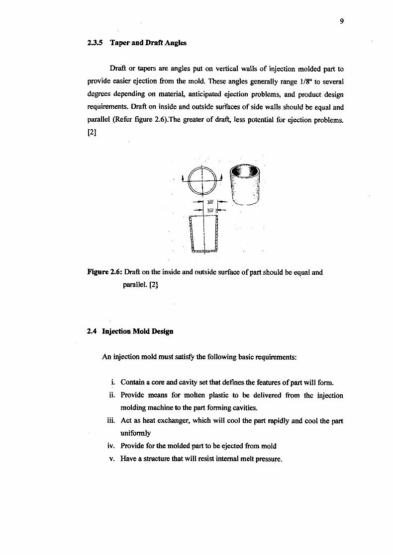
2.3.5 Taper and Draft Angles
Draft or tapers are angles put on vertical walls of injection molded part to
provide easier ejection from the mold. These angles generally range 1/8° to several
degrees depending on material, anticipated ejection problems, and product design
requirements. Draft on inside and outside surfaces of side walls should be equal and
parallel (Refer figure 2.6).The greater of draft, less potential for ejection problems.
[2]
Figure 2.6: Draft on the inside and outside surface of part should be equal and
parallel. [2]
2.4 Injection Mold Design
An injection mold must satisfy the following basic requirements:
i. Contain a core and cavity set that defines the features of part will form.
ii. Provide means for molten plastic to be delivered from the injection
molding machine to the part forming cavities.
iii. Act as heat exchanger, which will cool the part rapidly and cool the part
uniformly
iv. Provide for the molded part to be ejected from mold
v. Have a structure that will resist internal melt pressure.
10
vi. In multicavity molds, provide uniformly to each cavity through
dimension, melt delivery, and cooling
All of the above is done with mold steel tolerances often as little as ±0.00508
mm (0.0002 in). [1]
2.4.1 Type of Injection Mold
There are three basic types of molds:
L The cold-runner two plate mold (design is simplest)
ii. The cold-runner three-plate mold, in which the runner system is separated
from the part when the mold opens.
iii. The hot-runner mold (also called runnerless mold), in which the molten
plastic is kept hot in a heated runner plate.
In cold-runner molds, the solidified plastic in the channels that connect the
mold cavity to the end of the barrel must be removed, usually by trimming. This
scrap can be chopped and recycled. In hot-runner molds, which are more expensive,
there are no gates, runners, or sprue attached to the molded part. Cycle times are
shorter,. because only injection molded part must be cooled and ejected. [6]
2.4.2 Standard Mold Assembly
Basic type mold called "two plate molds". When the mold opens, the mold is
divided into two blocks of fixed side (cavity side) and the movable side (core side).
The ejector mechanism is provided on the movable sided
11
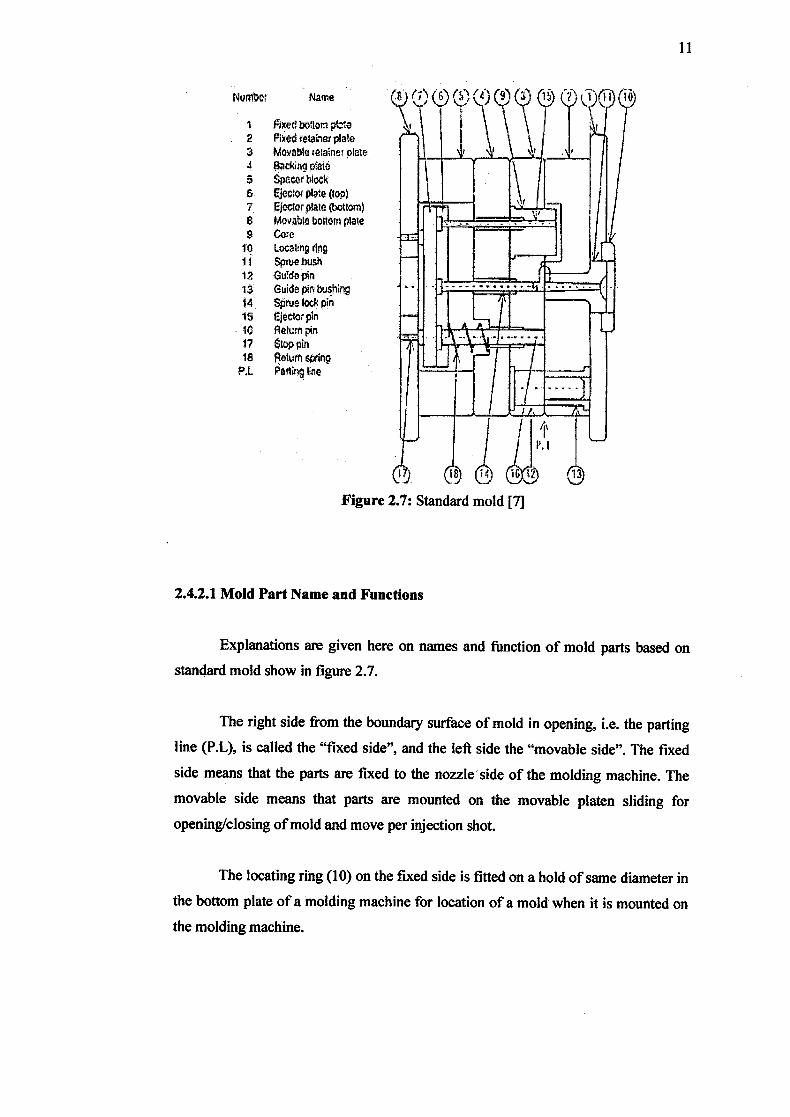
Num1er Name
Fixed bottom, pii 2 Fixed velainer plate a Movable retainer plate 4 Backing plate S $peTblock &.
Eiectof plate (top) 7 Ejector plate (bottom) 8 Movable boUocn plate 9 Core 1 ILOCtg dng ii Sptie bush 12 CiiTde pin 13 Guide pin bushing 14 Seiodcpin 15 Eiector pin 16 Return pin 17 Stop pin IA Return spring
P.1 Parting litie
Figure 2.7: Standard mold [7]
2.4.2.1 Mold Part Name and Functions
Explanations are given here on names and function of mold parts based on
standard mold show in figure 2.7.
The right side from the boundary surface of mold in opening, i.e. the parting
line (P.L), is called the "fixed side", and the left side the "movable side". The fixed
side means that the parts are fixed to the nozzle side of the molding machine. The
movable side means that parts are mounted on the movable platen sliding for
opening/closing of mold and move per injection shot.
The locating ring (10) on the fixed side is fitted on a hold of same diameter in
the bottom plate of a molding machine for location of a mold when it is mounted on
the molding machine.