Embed Size (px)
Citation preview

Purdue UniversityPurdue e-PubsInternational Refrigeration and Air ConditioningConference School of Mechanical Engineering
2018
Conceptual Design of a Manufacturing Process foran Automotive Microchannel Heat ExchangerBrian PaulOregon State University, United States of America, [email protected]
Chuankai SongOregon State University, United States of America, [email protected]
Kijoon LeeOregon State University, United States of America, [email protected]
Brian M. FronkOregon State University, United States of America, [email protected]
Dipankar SahooTenneco Inc., United States of America, [email protected]
See next page for additional authors
Follow this and additional works at: https://docs.lib.purdue.edu/iracc
This document has been made available through Purdue e-Pubs, a service of the Purdue University Libraries. Please contact [email protected] foradditional information.Complete proceedings may be acquired in print and on CD-ROM directly from the Ray W. Herrick Laboratories at https://engineering.purdue.edu/Herrick/Events/orderlit.html
Paul, Brian; Song, Chuankai; Lee, Kijoon; Fronk, Brian M.; Sahoo, Dipankar; and Shipley, Michael, "Conceptual Design of aManufacturing Process for an Automotive Microchannel Heat Exchanger" (2018). International Refrigeration and Air ConditioningConference. Paper 2052.https://docs.lib.purdue.edu/iracc/2052

AuthorsBrian Paul, Chuankai Song, Kijoon Lee, Brian M. Fronk, Dipankar Sahoo, and Michael Shipley
This conference paper is available at Purdue e-Pubs: https://docs.lib.purdue.edu/iracc/2052
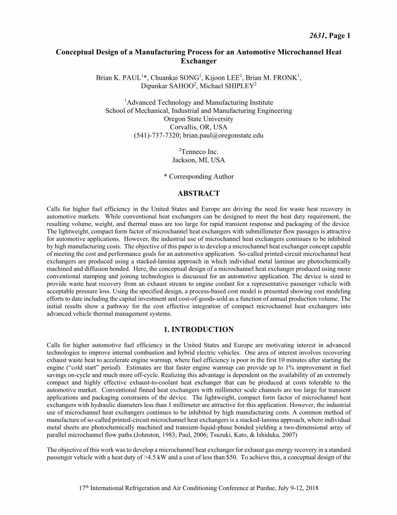
2631, Page 1
17th International Refrigeration and Air Conditioning Conference at Purdue, July 9-12, 2018
Conceptual Design of a Manufacturing Process for an Automotive Microchannel Heat Exchanger
Brian K. PAUL1*, Chuankai SONG1, Kijoon LEE1, Brian M. FRONK1,
Dipankar SAHOO2, Michael SHIPLEY2
1Advanced Technology and Manufacturing Institute School of Mechanical, Industrial and Manufacturing Engineering
Oregon State University Corvallis, OR, USA
(541)-737-7320; [email protected]
2Tenneco Inc. Jackson, MI, USA
* Corresponding Author
ABSTRACT
Calls for higher fuel efficiency in the United States and Europe are driving the need for waste heat recovery in automotive markets. While conventional heat exchangers can be designed to meet the heat duty requirement, the resulting volume, weight, and thermal mass are too large for rapid transient response and packaging of the device. The lightweight, compact form factor of microchannel heat exchangers with submillimeter flow passages is attractive for automotive applications. However, the industrial use of microchannel heat exchangers continues to be inhibited by high manufacturing costs. The objective of this paper is to develop a microchannel heat exchanger concept capable of meeting the cost and performance goals for an automotive application. So-called printed-circuit microchannel heat exchangers are produced using a stacked-lamina approach in which individual metal laminae are photochemically machined and diffusion bonded. Here, the conceptual design of a microchannel heat exchanger produced using more conventional stamping and joining technologies is discussed for an automotive application. The device is sized to provide waste heat recovery from an exhaust stream to engine coolant for a representative passenger vehicle with acceptable pressure loss. Using the specified design, a process-based cost model is presented showing cost modeling efforts to date including the capital investment and cost-of-goods-sold as a function of annual production volume. The initial results show a pathway for the cost effective integration of compact microchannel heat exchangers into advanced vehicle thermal management systems.
1. INTRODUCTION Calls for higher automotive fuel efficiency in the United States and Europe are motivating interest in advanced technologies to improve internal combustion and hybrid electric vehicles. One area of interest involves recovering exhaust waste heat to accelerate engine warmup, where fuel efficiency is poor in the first 10 minutes after starting the engine (“cold start” period). Estimates are that faster engine warmup can provide up to 1% improvement in fuel savings on-cycle and much more off-cycle. Realizing this advantage is dependent on the availability of an extremely compact and highly effective exhaust-to-coolant heat exchanger that can be produced at costs tolerable to the automotive market. Conventional finned heat exchangers with millimeter scale channels are too large for transient applications and packaging constraints of the device. The lightweight, compact form factor of microchannel heat exchangers with hydraulic diameters less than 1 millimeter are attractive for this application. However, the industrial use of microchannel heat exchangers continues to be inhibited by high manufacturing costs. A common method of manufacture of so-called printed-circuit microchannel heat exchangers is a stacked-lamina approach, where individual metal sheets are photochemically machined and transient-liquid-phase bonded yielding a two-dimensional array of parallel microchannel flow paths.(Johnston, 1983; Paul, 2006; Tsuzuki, Kato, & Ishiduka, 2007) The objective of this work was to develop a microchannel heat exchanger for exhaust gas energy recovery in a standard passenger vehicle with a heat duty of >4.5 kW and a cost of less than $50. To achieve this, a conceptual design of the

2631, Page 2
17th International Refrigeration and Air Conditioning Conference at Purdue, July 9-12, 2018
heat exchanger was specified using a standard effectiveness-NTU approach. Next, a conceptual design of the manufacturing process was developed along with a bottom-up production cost model to determine if there is a realistic path for manufacturing microchannel heat exchangers at a cost of goods sold (COGS) and capital investment necessary to enter the market. Model, method and results are presented below.
2. CONCEPTUAL DESIGN OF THE HEAT EXCHANGER The heat exchanger in this study was designed to transfer waste heat from the exhaust stream of the engine to the engine coolant. A schematic of the waste heat recovery system is shown in Figure 1. The waste heat recovered from the hot exhaust (red) to the coolant (yellow) helps to increase the temperature of the engine within the first few minutes after ignition. The heat exchanger was expected to transfer 4.5 kW of power from exhaust entering at 350°C and 0.014 kg/s to coolant with an inlet temperature 20°C, inlet pressure of 207 kPa, and flow rate of 0.18 kg/s. The maximum allowable pressure drop was approximately 1 kPa for the exhaust and 3.75 kPa for the coolant. A cross-flow geometry was chosen for the heat exchanger. Initial efforts were made to conceptualize a heat exchanger that could leverage more conventional automotive materials and manufacturing technology. The service environment affects material selection, which also affects the manufacturing process design. In this case, the service environment included an exhaust gas at 350°C and 30 psi differential between the two streams. Stainless steel 439 was chosen based on cost, formability, oxidation resistance and mechanical strength at these temperatures, opening the option of conventional stamping and joining technologies in process selection. A conceptual design of the cross-flow heat exchanger is shown in Figure 2. The heat exchanger consists of a stack of laser-welded heat exchanger coolant plates that are inserted and brazed, along with top and bottom stiffening plates, into two face plates. Subsequently, stamped coolant headers are gas tungsten arc welded along the interface with the top, bottom and face plates to provide plenums for the flow distribution of the coolant. Based on inlet conditions and desired heat duty, expressions for UA and NTU were formulated in terms of the exhaust, channel wall and coolant thermal resistances to specify the channel dimensions. The heat transfer coefficients and friction factor of the coolant and exhaust were determined from duct flow correlations for laminar flow. With this approach, the critical dimensions of the heat exchanger were found to be the height of the coolant and exhaust channels as 600 µm and 528 µm, respectively. The overall size of the lamina stack is expected to be approximately 30 mm long x 100 mm wide x 50 mm high.
3. CONCEPTUAL DESIGN OF THE MANUFACTURING PROCESS In collaboration with industry partners, recent work at the Oregon State University (OSU) Advanced Technology and Manufacturing Institute (ATAMI) has focused on developing and qualifying manufacturing process designs using process-based cost models for validating the performance and cost of microchannel components.(Lajevardi, Leith, King, & Paul, 2011; Leith, King, & Paul, 2010) A complete manufacturing process design involves the manufacturing process flow needed to produce a product and the detail design of each process step including specification of the machine tool, process parameters, touch tooling design and workpiece. The scope of the manufacturing process design concept in this project was on determining the process flow for manufacturing the heat exchanger and identifying the machine tools, feasible process parameters and cost elements necessary to evaluate whether cost targets can be
Figure 1: Waste heat recovery system enabled by the microchannel heat exchanger

2631, Page 3
17th International Refrigeration and Air Conditioning Conference at Purdue, July 9-12, 2018
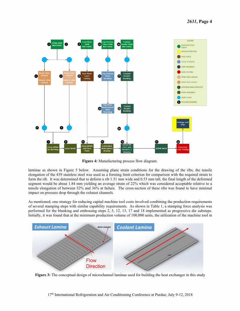
achieved. The process-based cost model (Gao, Lizarazo-Adarme, Paul, & Haapala, 2016) used to evaluate the design provides the capital investment and COGS as a function of annual production volume for setting up a greenfield site. Estimates for constituent costs and process parameters were determined by: i) experience developing related process models; ii) through interaction with industrial partner; iii) through interactions with machine tool vendors; and iv) by reviewing the technical literature. The cost model was developed for a market demand of between 100,000 and one million devices per year. Cost targets for the manufacturing process design were set to be less than $50 in the production volumes of interest. The manufacturing process flow diagram for the heat exchanger is shown in Figure 4. The general concept for producing the heat exchanger consists of first stamping metal sheets into microchannel laminae that are below one mm in thickness (Figure 3). To reduce capital machine tool costs, one stamping press was chosen in a progressive die format to increase the throughput of laminae and reduce forming forces per step. Next, the stamped laminae were laser welded together to form heat exchanger plates for the coolant flow. The heat exchanger has 27 exhaust laminae and 26 coolant laminae which when laser welded, form 26 laminae pairs along with a bottom single exhaust lamina. This configuration permits the exhaust to envelope both sides of all coolant channels. Face plates, top plates and bottom plates were all designed to be several mm thick. The size of the through features in the face plates were expected to be difficult to punch. Therefore, laser cutting was chosen for patterning face plates. Due to larger feature sizes, blanking and punching operations were chosen for the top and bottom plates. The brazing of the laser-welded plates with the face, top and bottom plates was expected to be carried out on a controlled-atmosphere belt furnace using brazing fixtures. A stamped coolant header was then gas tungsten arc welded to the plates in order to form a coolant plenum. The cost of interconnects to connect the heat exchanger with the exhaust and cooling systems were not considered in the cost models below. Finally, it was assumed that ultrasonic cleaning steps were required prior to all joining operations. Based on prior cost modeling efforts, the bulk of the processing costs were expected to be in the stamping and laser welding steps. For stamping operations, design efforts included considering 1) the formability of the workpiece, 2) grouping operations around force requirements and 3) sizing the capacity of the stamping press. A simple formability analysis was conducted consisting of evaluating whether the plane strain needed to produce key features in the laminae would exceed the elongation of the material. For the formability analysis, the features of interest were the ribs in both
Figure 2: The conceptual design of a microchannel heat exchanger for the automotive application in this study
2631, Page 4
17th International Refrigeration and Air Conditioning Conference at Purdue, July 9-12, 2018
laminae as shown in Figure 5 below. Assuming plane strain conditions for the drawing of the ribs, the tensile elongation of the 439 stainless steel was used as a forming limit criterion for comparison with the required strain to form the rib. It was determined that to deform a rib 1.51 mm wide and 0.53 mm tall, the final length of the deformed segment would be about 1.84 mm yielding an average strain of 22% which was considered acceptable relative to a tensile elongation of between 32% and 36% at failure. The cross-section of these ribs was found to have minimal impact on pressure drop through the exhaust channels. As mentioned, one strategy for reducing capital machine tool costs involved combining the production requirements of several stamping steps with similar capability requirements. As shown in Table 1, a stamping force analysis was performed for the blanking and embossing steps 2, 5, 12, 13, 17 and 18 implemented as progressive die substeps. Initially, it was found that at the minimum production volume of 100,000 units, the utilization of the machine tool in
Figure 3: The conceptual design of microchannel laminae used for building the heat exchanger in this study
Figure 4: Manufacturing process flow diagram.

2631, Page 5
17th International Refrigeration and Air Conditioning Conference at Purdue, July 9-12, 2018
each process step was between 2% to 4% suggesting excessive capacity. Purchasing one press capable of meeting all force requirements resulted in a reduction of capital costs, increasing the percent utilization of the production press to 28.5%. Given a maximum utilization of 80%, this one machine tool is capable of providing capacity to just under 300,000 units. The cycle time and capacity calculations in Table 1 were determined based on experiences with stamping of 439 stainless steel at Tenneco. One area of the process flow diagram requiring considerable vendor engagement was the brazing step. Based on interactions with brazing alloy vendors, it was determined that a nickel-chrominum-silicon-boron-iron braze alloy AMS 4777 (commonly known as BNi-2) would be used for the braze joints at the face plates due to the need for good flowability and large fillets. The current concept is to apply the braze alloy as a paste. Brazing temperature is just over 1000°C requiring either vacuum or inert environments. From a capacity consideration, controlled atmosphere brazing allows for the use of a conveyorized belt furnace, in this case a Seco/Warwick model MBC-24812.
4. PROCESS-BASED COST MODELING To evaluate the manufacturing process design relative to cost targets, a production cost model was developed, capable of estimating the cost of goods sold (COGS) for the heat exchanger. The cost model was built from the bottom up by adding the raw material costs to the processing costs for each process step. Processing costs were determined based
Figure 5: Design of laminae ribs based on a formability analysis
Table 1: Capability and capacity analyses for stamping process steps at 100,000 units per year. Substep numbers beyond the decimal indicate a progressive tool setup on the machine tool. Rightmost gray areas shows percent utilization of machine tool and percentage that each step will use the tool. Bottom gray area shows the
machine tool capability needed to satisfy all steps.
2631, Page 6
17th International Refrigeration and Air Conditioning Conference at Purdue, July 9-12, 2018
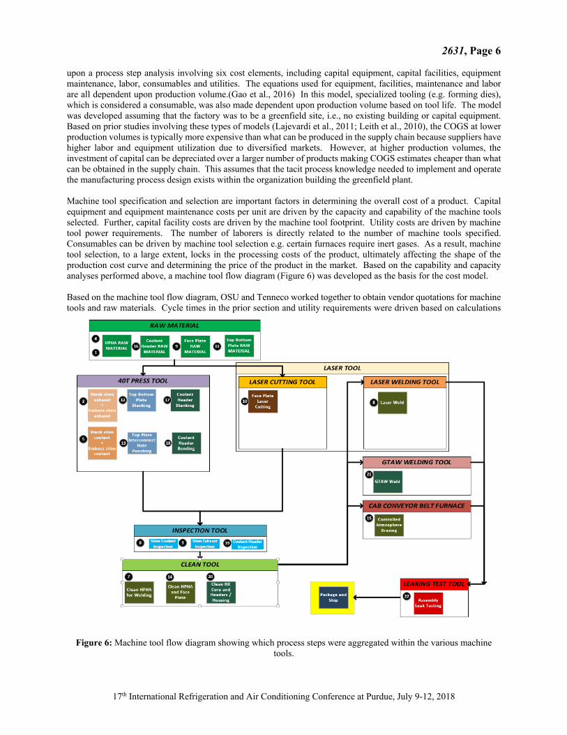
upon a process step analysis involving six cost elements, including capital equipment, capital facilities, equipment maintenance, labor, consumables and utilities. The equations used for equipment, facilities, maintenance and labor are all dependent upon production volume.(Gao et al., 2016) In this model, specialized tooling (e.g. forming dies), which is considered a consumable, was also made dependent upon production volume based on tool life. The model was developed assuming that the factory was to be a greenfield site, i.e., no existing building or capital equipment. Based on prior studies involving these types of models (Lajevardi et al., 2011; Leith et al., 2010), the COGS at lower production volumes is typically more expensive than what can be produced in the supply chain because suppliers have higher labor and equipment utilization due to diversified markets. However, at higher production volumes, the investment of capital can be depreciated over a larger number of products making COGS estimates cheaper than what can be obtained in the supply chain. This assumes that the tacit process knowledge needed to implement and operate the manufacturing process design exists within the organization building the greenfield plant. Machine tool specification and selection are important factors in determining the overall cost of a product. Capital equipment and equipment maintenance costs per unit are driven by the capacity and capability of the machine tools selected. Further, capital facility costs are driven by the machine tool footprint. Utility costs are driven by machine tool power requirements. The number of laborers is directly related to the number of machine tools specified. Consumables can be driven by machine tool selection e.g. certain furnaces require inert gases. As a result, machine tool selection, to a large extent, locks in the processing costs of the product, ultimately affecting the shape of the production cost curve and determining the price of the product in the market. Based on the capability and capacity analyses performed above, a machine tool flow diagram (Figure 6) was developed as the basis for the cost model. Based on the machine tool flow diagram, OSU and Tenneco worked together to obtain vendor quotations for machine tools and raw materials. Cycle times in the prior section and utility requirements were driven based on calculations
Figure 6: Machine tool flow diagram showing which process steps were aggregated within the various machine tools.

2631, Page 7
17th International Refrigeration and Air Conditioning Conference at Purdue, July 9-12, 2018
or prior experience with various processes at OSU and Tenneco. Die costs, specialized tooling costs and tool lives were provided by Tenneco based on experience. Altogether, these cost parameters were organized into a data input table. Other key assumptions across all process steps are shown in Table 2.
5. RESULTS AND DISCUSSION
A MATLAB program was developed to take the data input table and data from Table 2 and generate the results shown in Figure 7. The MATLAB code conformed with calculations consistent with prior cost modeling efforts (Gao et al., 2016) and a second Excel file was developed to verify calculations. A breakout of these costs is provided by process step and by cost element as shown in Figure 8 and Figure 9, respectively. 5.1 Unit Cost and Capital Cost Figure 7 shows the change in unit cost and capital equipment and facilities as a function of production volume. From the plot, capital costs increase significantly beyond 200,000 units per year, which is consistent with the capacity analyses discussed above. As described, the capacity of the stamping operations was designed to be around 300,000 units per year. As shown in Figure 7, the heat exchanger costs move toward a minimum between 200,000 and 500,000 units per year. Minimal savings are found beyond 500,000 units per year. The production volume at which the COGS is minimized is considered the knee in the curve. The implication of capacity considerations is that proper sizing of machine tools dictates where the knee in the production cost curve is, which is a key factor in minimizing COGS at required production volumes. This is because, in general, labor and equipment utilization drops beyond the knee in the curve due to the addition of machine tools to handle increased production. Beyond that, the COGS can approach but not exceed the utilization achieved at the knee in the production cost curve. At the production volumes of interest, the total COGS ranges between $18 and $27 per unit (without interconnects) which is well below the cost target of $50 per unit. This improvement in cost is mainly due to higher utilization of capital tooling and labor at higher production volumes. In addition, there is a significant change in consumables as a function of production volume, mainly due to better utilization of specialized tooling which is considered a consumable due to having a finite life prior to rehabilitation. In this model, raw material and utilities were not made dependent upon production volume.
Table 2: Additional parameteric data used across all process steps, developed in concert with Tenneco and machine tool vendors to supplement the data input table.
Category Parameters Units Description Values
Tool T_i % of capital Tool installation cost 10%
y_t Years/tool Amortized life of tool 10
Y_t % Yield of manufacturing process
U_t % Maximum Utilization of tool
h_y Hours/year Hours per year 4608
Facility B_A $/m2 Building cost per m2 1000
K_bt Multiplier for workspace 3
K_so Multiplier (for storage & office) 2
y_b yrs/building Amortized life of building 30
L $/person∙year Annual labor cost $50,000
R Average labor loading rate 1.5
p_t People/tool Number of laborers per tool 1
e_t Percent/year Annual maintenance as % of tool cost 5%
Utilities u_c,1 $/kWh *#part Electricity cost per kWh 0.051
u_c,2 $/gal DI Water cost per gal 0.004
u_c,3 $/gal Wastewater & Sewer cost per gal 0.009
Labor
Maintenance
80%

2631, Page 8
17th International Refrigeration and Air Conditioning Conference at Purdue, July 9-12, 2018
Based on the breakout by process step (Figure 8), raw material moves toward one-third of the unit cost at higher production volumes where stamping, laser welding and brazing costs are minimized. A major cost driver in the production volumes of interest is cleaning. To better understand the source of this cost, Figure 9 shows that between 20% and 33% of the cost is in utilities. In the current model, the cleaning step requires large amounts of electricity and water. It is expected that the utilities for the cleaning step are greatly overestimated and that this cost can be significantly reduced with more detailed analysis. This suggests that current COGS estimates are conservative. 5.2 Sensitivity Analysis To better understand the effect of various parameters in the cost model, a parametric sensitivity analysis was conducted in which each parameter was changed ± 10% to evaluate the effect on COGS. Parameters were prioritized based on the degree of impact to COGS which was determined to be $17.89 at a production volume of 2,000,000 units/year. This market condition was considered since it is well beyond the knee in the curve and, therefore, was considered to be representative of the minimum COGS. The top twelve cost parameters are shown in Figure 10. Note that most parameters are directly proportional to COGS (e.g. utility unit cost) with the exception of the tool capacities (i.e. number of parts per hour) which are inversely proportional. Insight from the sensitivity analysis is important for considering how to reduce COGS for larger markets. The cleaning steps were found to have the largest impact on COGS, which is confirmed by the pie charts. In particular, the waste water and sewage unit costs and usage for the ultrasonic cleaning of the two laminae were found to be the most significant cost drivers. These parameters for cleaning the various plates was also found to be substantial. It is likely that usage of waste water disposal systems is overestimated. One way to reduce these usage values would be to consider a waste water reclamation system. Deionized water unit cost and usage were also found to be significant for cleaning the laminae. Additional efforts are needed to investigate the utility requirements of all cleaning steps.
Figure 7: Results from cost modeling effort showing unit cost as a function of production volume. Capital
equipment and capital facilities are plotted on the secondary y-axis on the right.

2631, Page 9
17th International Refrigeration and Air Conditioning Conference at Purdue, July 9-12, 2018
Figure 8: Detailed costs by process step
Figure 9: Detailed costs by cost element

2631, Page 10
17th International Refrigeration and Air Conditioning Conference at Purdue, July 9-12, 2018
The next most important cost parameter was found to be the tool capacity for laser welding the laminae. This suggests opportunities to work on reducing the cycle time of the laser welding operation. The biggest opportunity would be to increase the scanning speed of the laser by increasing the power of the laser. A tradeoff analysis would be needed to determine whether this is economical. The tool capacity for laser cutting of the face plate was also found to be significant. This is surprising given the relatively small number of face plates produced. Optimization of scanning speed and material thickness is important here. Beyond this, the unit cost of the raw material becomes important. As production volume increases, the contribution of the raw material cost becomes magnified since raw material cost is not dependent on production volume. Based on past experience, raw material is typically around one third of COGS for mechanical assemblies made out of lower cost engineering materials. In this case, raw material costs are approaching one-third of COGS. These findings suggest that material and processing costs are approaching a reasonable equilibrium at the production volumes of interest. Not much can be done to improve the unit cost of the raw material. Lastly and surprisingly, heat exchanger costs are next most influenced by the unit cost and usage of shielding gas in the gas tungsten arc welding step. This is surprising because there are many fewer gas tungsten arc welds than laser welds or stampings. Additional effort is needed to review shielding gas requirements.
$17.79
$17.79
$17.78
$17.78
$18.06
$17.75
$17.75
$17.75
$17.74
$18.06
$17.65
$17.65
$18.00
$18.00
$18.00
$18.00
$17.81
$18.03
$18.03
$18.03
$18.04
$17.73
$18.13
$18.13
$17.60 $17.70 $17.80 $17.90 $18.00 $18.10 $18.20
q_u,2
u_c,2
q,c11
c,11
C_t
M_m,p
q_u,3
u_c,3
M_m,p
C_t
q_u,3
u_c,3
USD/Device
+10%
‐10%
Parameters Units Description Process Step
u_c,3 $/gal Wastewater & sewage unit cost Cleaning for laminae A and B prior to laser welding
q_u,3 gal/part Wastewater & sewage usage per part Cleaning for laminae A and B prior to laser welding
C_t Parts/hr∙tool Tool capacity = 1/cycle time Laser welding of laminae A and B
M_m,p $/kg 439 SS Raw material unit cost Exhaust laminae
u_c,3 $/gal Wastewater & sewage unit cost Cleaning laminae and plates prior to brazing
q_u,3 gal/part Wastewater & sewage usage per part Cleaning laminae and plates prior to brazing
M_m,p $/kg 439 SS Raw material unit cost Coolant laminae
C_t Part/hr∙tool Tool capacity = 1/cycle time Laser cutting of face plate
c,11 $/cu. Ft Shielding gas unit cost GTAW welding of coolant headers
q,c11 cu. ft/part Shielding gas usage per part GTAW welding of coolant headers
u_c,2 $/gal Deionized water unit cost Cleaning for laminae A and B prior to laser welding
q_u,2 gal/part Deionized water use per device Cleaning for laminae A and B prior to laser welding

2631, Page 11
17th International Refrigeration and Air Conditioning Conference at Purdue, July 9-12, 2018
6. CONCLUSIONS
In this study, a conceptual design of a microchannel heat exchanger was developed along with a conceptual design of the manufacturing process to produce the heat exchanger in an effort to explore the feasibility of deploying microchannel technology within automotive markets. Results from conceptual studies show a potential path to market adoption. Detailed analyses show that at production volumes of interest, ultrasonic cleaning dominates the cost. Sensitivity analysis of the cleaning costs suggest that waste water disposal and deionized water requirements should be further analyzed for cleaning parts prior to laser welding and brazing. Sensitivity analysis also showed that the cycle times for laser welding and laser cutting should be optimized and that shielding gas requirements in gas tungsten arc welding should be further considered. Reliability analysis of the conceptual design and validation of the manufacturing cost model is proposed as the next step. Upon finishing reliability analyses, specific areas of future investigation are needed regarding cleaning and shielding gas requirements, laser welding and laser cutting optimization, and robotic insertion of laminae pairs into face plates for supporting downsteam brazing. Ultimately, cost model validation will be pursued by producing and testing heat exchangers that are fabricated using the same process physics and process parameters as specified in the cost model.
REFERENCES Gao, Q., Lizarazo-Adarme, J., Paul, B. K., & Haapala, K. R. (2016). An economic and environmental assessment
model for microchannel device manufacturing: part 1–Methodology. Journal of Cleaner Production, 120, 135-145.
Johnston, A. (1983). Printed Circuit Heat Exchangers. Paper presented at the Chemeca 83: Chemical Engineering Today; Coping with Uncertainty; the Eleventh Australian Chemical Engineering Conference.
Lajevardi, B., Leith, S. D., King, D. A., & Paul, B. K. (2011). Arrayed microchannel manufacturing costs for an auxiliary power unit heat exchanger. Paper presented at the IIE Annual Conference. Proceedings.
Leith, S. D., King, D. A., & Paul, B. (2010). Toward Low-Cost Fabrication of Microchannel Process Technologies-Cost Modeling for Manufacturing Development. Retrieved from
Paul, B. K. (2006). Micro energy and chemical systems (MECS) and multiscale fabrication Micromanufacturing and nanotechnology (pp. 299-355): Springer.
Tsuzuki, N., Kato, Y., & Ishiduka, T. (2007). High performance printed circuit heat exchanger. Applied Thermal Engineering, 27(10), 1702-1707.