Embed Size (px)
Citation preview
CONCEPTUAL 3D DESIGN OF BATCH DISTILLATION COLUMN BY USING
AVEVA PDMS
BY
TAUFIK BIN ABU BAKAR (KA09094)
Thesis submitted in fulfilment of the requirements for the award of the degree of
Bachelor of Chemical Engineering in Chemical Engineering
Supervise by: Dr IngMohdRizza Bin Othman
Faculty of Chemical Engineering and Natural Resources
UNIVERSITI MALAYSIA PAHANG
JANUARY 2013
v
ABSTRACT
The main objective of this project is to design a 3D view of distillation
column for biodiesel process using AVEVA PDMS. The design constraints specify
that the biodiesel distillation column must be sized to fit into a standard truck-trailer.
3D design is a significant to solve the 2D design problem. The first step of this
project is drawing process flow diagram (PFD) for biodiesel process.After that the
simulation and sizing begin. Simulation is based on PFD and is done using ASPEN
Plus. After that the resident time for distillation column can be obtained. Then the
Process and Instrumentation Diagram (P&ID) will be drawn. All the control systems
are included in the P&ID before 3D design. This is important to ensure the safety of
equipment. After completion of P&ID, simulation process and the size of the reactor
in the form of 3D can be done. All parameter involved before will be used in 3D
design. 3D design is done by using AVEVA PDMS. As a result, by using AVEVA
PDMS software the design will be more accurate. This software prove that the 3D
design give more benefit compare to the 2D design. The end result is better product,
size can be optimized and no faults in design for example equipment layout and pipe
clashing. For recommendation the design structure must be including in the plant for
example rack to support the equipment, the size of the trailer can also be changed
and more safety precaution has to be taken in design.
vi
ABSTRAK
Objektif utama projek ini adalah untuk mereka bentuk model 3D untuk
proses biodiesel menggunakan AVEVA PDMS. Had reka bentuk untuk biodiesel
kolum penyulingan mestilah dapat dimuatkan ke dalam sebuah lori treler standard.
Reka bentuk 3D adalah penting untuk menyelesaikan masalah reka bentuk 2D.
Langkah pertama projek ini melukis gambarajah aliran proses (PFD) untuk biodiesel
process. Selepas itu, simulasi dan pengiraan untuk saiz bermula. Simulasi
berdasarkan PFD dan dilakukan dengan menggunakan Aspen Plus. Kemudian Proses
dan Instrumentasi Rajah (P&ID) akan dilukis. Semua sistem kawalan dimasukkan
dalam P&ID sebelum reka bentuk 3D. Ini adalah penting untuk memastikan
keselamatan peralatan. Selepas selesai P&ID, proses simulasi dan saiz reaktor dalam
bentuk 3D boleh dilakukan. Semua parameter yang terlibat sebelum ini akan
digunakan dalam reka bentuk 3D. Reka bentuk 3D dilakukan dengan menggunakan
AVEVA PDMS. Hasilnya, dengan menggunakan AVEVA PDMS perisian reka
bentuk akan menjadi lebih tepat. Perisian ini membuktikan bahawa reka bentuk 3D
memberi manfaat yang lebih berbanding dengan reka bentuk 2D. Hasilnya adalah
produk yang lebih baik, saiz boleh dioptimumkan dan tiada kesilapan dalam reka
bentuk bagi susun atur peralatan seperti „pipe clash‟. Untuk cadangan struktur reka
bentuk mesti termasuk dalam design seperti rak untuk menyokong peralatan, saiz
treler juga boleh berubah dan keselamatan langkah berjaga-jaga perlu diambil dalam
reka bentuk.
vii
TABLE OF CONTENTS
Page
SUPERVISOR’S DECLARATION ii
STUDENT’S DECLARATION iii
ACKNOWLEDGEMENTS iv
ABSTRACT v
ABSTRAK vi
TABLE OF CONTENT vii
LIST OF FIGURES ix
CHAPTER 1 INTRODUCTION
CHAPTER 2 LITERATURE REVIEW
1.1
1.2
1.3
1.4
1.5
1.6
1.7
Background of The Proposed Study
Problem Statement
Research Objective
Scope of Proposed Study
Expected Outcomes
Significant of proposed study
Thesis overview
1
2
3
3
3
3
3
2.1
2.2
2.2.1
2.3
2.3.1
2.3.1.1
2.3.1.2
2.3.1.3
2.3.1.4
2.3.2
Benefit 3D Design Compare 2D Design
Batch Distillation
Application of Batch Distillation
Background of biodiesel
Transesterification of triglycerides to biodiesel
Catalytic transesterification methods
Acid-catalytic transesterification method
Alkali-catalytic transesterification methods
Enzyme-catalyzed transesterification Methods
Non-catalytic transesterification methods
4
7
8
9
10
10
11
12
14
16
viii
CHAPTER 3 METHODOLOGY
CHAPTER 4 RESULT AND DISCUSSION
CHAPTER 5 CONLUSION AND RECOMMENDATION
2.3.2.1
2.3.2.2
BIOX co-solvent process
Supercritical alcohol transesterification
16
17
3.1
3.2
3.3
3.4
PFD
SIMULATION AND SIZING
P&ID
DESIGN USING AVEVA PDMS
19
21
23
24
4.1
4.1.1
4.1.2
4.1.3
4.2
4.2 .1
4.2.2
Result
View of biodiesel plant using aveva pdms
equipment
Equipment with piping
equipment in research
Discussion
Plant layout
P&ID Process Description
31
31
31
34
36
40
40
41
5.1
5.2
Conclusion
Recommendation
REFERENCES
APPENDICES
44
45
46
ix
LIST OF FIGURES
Figure Number Title Page
2.1 Batch Distillation 8
2.2 Transesterification of biodiesel 9
2.3 Mechanism of the acid-catalyzed transesterification 12
2.4
Mechanism of the alkali-catalyzed transesterification of
vegetable oils 14
3.1 Distillation Column equipment and piping 29
3.2 Distillation Column Isometric View 1 30
3.3 Distillation Column Isometric View 2 30
4.1 Equipment Isometric 1 31
4.2 Equipment Isometric 2 32
4.3 Equipment Isometric 3 32
4.4 Equipment Isometric 4 33
4.5 Equipment with piping Isometric 1 34
4.6 Equipment with piping Isometric 2 34
4.7 Equipment with piping Isometric 3 35
4.8 Equipment with piping Isometric 4 35
1
CHAPTER 1
INTRODUCTION
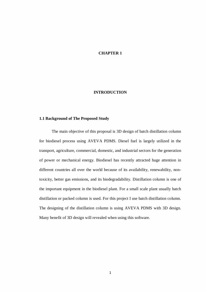
1.1 Background of The Proposed Study
The main objective of this proposal is 3D design of batch distillation column
for biodiesel process using AVEVA PDMS. Diesel fuel is largely utilized in the
transport, agriculture, commercial, domestic, and industrial sectors for the generation
of power or mechanical energy. Biodiesel has recently attracted huge attention in
different countries all over the world because of its availability, renewability, non-
toxicity, better gas emissions, and its biodegradability. Distillation column is one of
the important equipment in the biodiesel plant. For a small scale plant usually batch
distillation or packed column is used. For this project I use batch distillation column.
The designing of the distillation column is using AVEVA PDMS with 3D design.
Many benefit of 3D design will revealed when using this software.
2
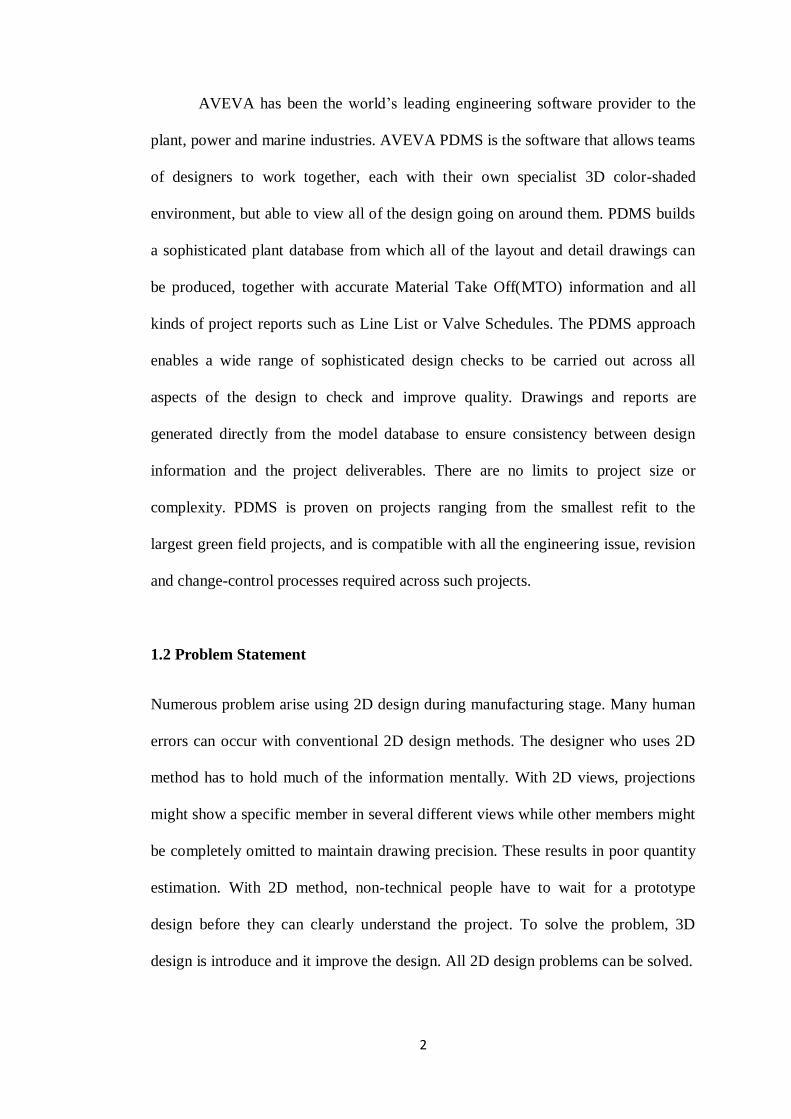
AVEVA has been the world‟s leading engineering software provider to the
plant, power and marine industries. AVEVA PDMS is the software that allows teams
of designers to work together, each with their own specialist 3D color-shaded
environment, but able to view all of the design going on around them. PDMS builds
a sophisticated plant database from which all of the layout and detail drawings can
be produced, together with accurate Material Take Off(MTO) information and all
kinds of project reports such as Line List or Valve Schedules. The PDMS approach
enables a wide range of sophisticated design checks to be carried out across all
aspects of the design to check and improve quality. Drawings and reports are
generated directly from the model database to ensure consistency between design
information and the project deliverables. There are no limits to project size or
complexity. PDMS is proven on projects ranging from the smallest refit to the
largest green field projects, and is compatible with all the engineering issue, revision
and change-control processes required across such projects.
1.2 Problem Statement
Numerous problem arise using 2D design during manufacturing stage. Many human
errors can occur with conventional 2D design methods. The designer who uses 2D
method has to hold much of the information mentally. With 2D views, projections
might show a specific member in several different views while other members might
be completely omitted to maintain drawing precision. These results in poor quantity
estimation. With 2D method, non-technical people have to wait for a prototype
design before they can clearly understand the project. To solve the problem, 3D
design is introduce and it improve the design. All 2D design problems can be solved.
3
1.3 Research Objective
To design the 3D view of batch distillation column of biodiesel using AVEVA
PDMS.
1.4 Scope of The Proposed Study
1.4.1 Create model and simulate batch distillation column.
1.4.2 Develop P&ID for the biodiesel plant.
1.4.3 Generate 3D design by using AVEVA PDMS
1.5 Expected Outcome
By using AVEVA PDMS the simulation and design of batch distillation column
become more fast, easy, accurate and precise.
1.6 Significant of proposed study:
To improve the quality of product 3D design was introduce. With 3D design,
designers can directly deal with customers. 3D design will facilitate the designer
work and increase customer confidence on the product.
1.7 Thesis overview
In the next chapter,the part that will be highlight first is to gather the information by
reviewing on the biodiesel process, 3D design, batch distillation and AVEVA PDMS
software. Secondly, the methodology on how to conduct the research on 3D design
of batch distillation for production of biodiesel.
4
CHAPTER 2
LITERATURE REVIEW
INTRODUCTION
2.1 BENEFIT 3D DESIGN COMPARE 2D DESIGN
In today‟s digital world, designers are demanding 3D to enhance their
designs and improve communication with their customers. Many inventors and
companies still use 2D drawings and are starting to realize the benefit of skipping the
2D step and starting off with a 3D design because 3D modeling can save time and
money as well as improve customer relations (Sheryl S et al., 1998. Making 2D
drawings is fast and easy, but the output is still a 2D drawing, which does not readily
work with downstream systems like purchasing and manufacturing. In some cases
2D drawings are sufficient but 90% of the time they are not. In prototyping, for
example, a 3D model has to be made because most of the prototyping machines
require 3D data. In fact, the majority of the machines used to manufacture parts need
3D computer-aided design (CAD) files and do not read 2D CAD drawings because
2D drawings do not contain all information needed to develop a three-dimensional
product.
5
When using 2D CAD drawings during the manufacturing stage, numerous
problems arise. Viewing 3D CAD models helps identify errors early(Jeongsam Yet
all). These errors can be found while simulating the matching and mating of parts.
Through the use of 3D CAD, the assembly process of any given product can be
simulated, visualized and analyzed before the design goes into production. 3D CAD
models are essential beforehand in determining the volume of material needed to
mold specific parts as well. The use of 3D CAD files also ensures that a design has
sufficient room for other parts within the design.
Through the use of 3DCAD modeling, engineers are able to create better
designs than meet the unique requirements of any client in a relatively short amount
of time. The internet has many tools that allow multiple individuals to communicate
and collaborate online. 3D models of products or parts can be analyzed and looked at
and edited in real time through the use of desktop sharing and/or a whiteboard. From
an esthetic point of view, the use 3DCAD is substantially more beneficial. A design
in 3D is more realistic and the engineer has a better ability to make a design more
attractive. Collaboration between fellow engineers, clients and suppliers comes at
greater ease because 3DCAD files are 3 dimensional models of a specific part or
application. It's much easier to communicate and collaborate when looking at a 3D
model simply because it‟s easier to point out elements and explain what changes
need to be made.
In addition, 3D CAD is not only advantages for determining the volume of
the entire project and of each part included within the design for the sole purpose of
6
knowing how much material is necessary to develop a certain quantity, but all
dimensions can be observed with ease. The total weight, width, height, length and
volume very often can be crucial elements in a design, especially when performing a
structural analysis and when meeting legal requirements. Testing specific
alternatives and dimension changes is simple not feasible without a 3D system.
Designers must find room for specific elements and components within the design.
Since 3D model data can be transferred to analysis and validation tools and used for
Computer Aided Manufacturing as well, it increases the accuracy of results and
saves time by eliminating the need to re-create data.
The use of 3DCAD models is replacing the use of 2DCAD drawings.
Because a 3D model provides much more detail, designers and engineers can
communicate product information and visualize complex parts and assemblies more
clearly.3DCAD is simply more accurate than 2D CAD drawings. The end result is
better product, optimized in size, weight with better performance, no faults in the
design, in less time, for less money. Its advanced nature allows designers to work on
more complex models. The use of 3DCAD technology reduces human error.
7
2.2 BATCH DISTILLATION
Batch distillation is an unsteady state operation. To handle small quantities of
material batch distillation is often preferable. Other than batch distillation packings
may be used in small plant. In batch distillation the quantity charged to the batch
usually fixed. The batch distillation column consist of pot as a reboiler , column as a
condenser, some off a portion of the condensed vapour (distillate) as reflux, and one
or more receivers. During operation the vapor passes upward through the column. At
the top the vapour is condensed imto liquid. Some of the liquid returned to the
column as reflux, and the major liquid withdraw as distillate. Batch distillation is
often preferable in small quantities compared to continuous because of some
advantage.
Advantage of batch distillation;
i. Economical for small volumes
ii. Flexible in accommodating changes in product formulation
iii. Flexible in modification of production rate
iv. Allow better product integrity: each batch of product can be clearly identified
in terms of the feeds involved and conditions of processing. This is
particularly important in industries such as pharmaceuticals and foodstuffs.
8
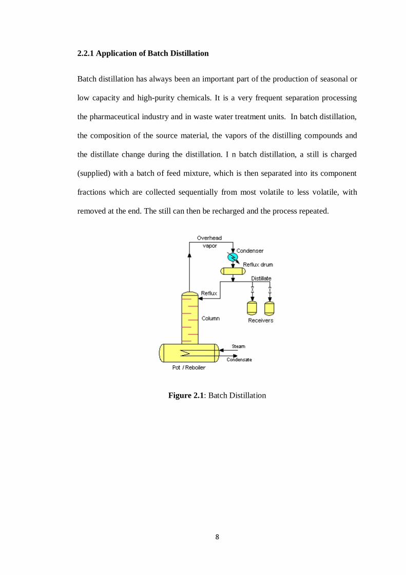
2.2.1 Application of Batch Distillation
Batch distillation has always been an important part of the production of seasonal or
low capacity and high-purity chemicals. It is a very frequent separation processing
the pharmaceutical industry and in waste water treatment units. In batch distillation,
the composition of the source material, the vapors of the distilling compounds and
the distillate change during the distillation. I n batch distillation, a still is charged
(supplied) with a batch of feed mixture, which is then separated into its component
fractions which are collected sequentially from most volatile to less volatile, with
removed at the end. The still can then be recharged and the process repeated.
Figure 2.1: Batch Distillation
9
2.3 Background of biodiesel
Biodiesel is an alternative fuel for diesel engines that is produced by chemically
reacting a vegetable oil or animal fat with an alcohol such as methanol. The reaction
requires a catalyst, usually a strong acid or base such as sulphuric acid sodium or
potassium hydroxide, and produces new chemical compounds called methyl esters. It
is these esters that have come to be known as biodiesel. (A. S. Ramadhas et al., 2004
).
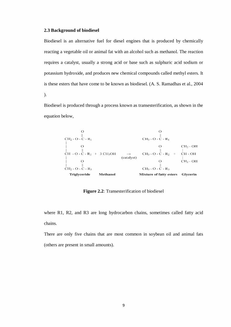
Biodiesel is produced through a process known as transesterification, as shown in the
equation below,
Figure 2.2: Transesterification of biodiesel
where R1, R2, and R3 are long hydrocarbon chains, sometimes called fatty acid
chains.
There are only five chains that are most common in soybean oil and animal fats
(others are present in small amounts).
10
2.3.1 Transesterification of triglycerides to biodiesel
There are four techniques transesterification methods. Amongst the four techniques,
chemical conversion (transesterification) of the oil to its corresponding fatty ester is
the most promising solution to the high viscosity problem. Sometimes, it is more
convenient to convert the alkyl group of an ester to another alkyl group. This process
is known as ester exchange or transesterification. Transesterification is the reversible
reaction of a fat or oil with an alcohol (methanol or ethanol) to form fatty acid alkyl
esters and glycerol. It can be alkali-, acid-, or enzyme-catalyzed; however, currently
the majority of the commercialized technology resides in transesterification using
alkali-catalyzed reaction (Ma F and Hanna MA., 1999). Mostly, biodiesel is derived
from the vegetable oils using sodium or potassium hydroxide catalytic
transesterification methanol process.
2.3.1.1 Catalytic transesterification methods
Transesterification reactions can be catalyzed by alkalis (Kotwal MS et all.,
2009),and acids (Miao X et all., 2009).The catalytic transesterification of vegetable
oils with methanol is an important industrial method used in biodiesel synthesis.
However, these catalytic systems are less active or completely inactive for long
chain alcohols. Usually, industries use sodium or potassium hydroxide or sodium or
potassium methoxide as catalyst, since they are relatively cheap and quite active for
this reaction (Macedo CCS et all., 2006). Enzymes-catalyzed procedures, using
lipase as catalyst, do not produce side reactions, but the lipases are very expensive
for industrial scale production and a three-step process was required to achieve a
95% conversion (Stavarache C et all., 2005).
11
2.3.1.2 Acid-catalytic transesterification methods
Biodiesel produced by transesterification reaction can be catalyzed by sulfuric,
phosphoric, hydrochloric and organic sulfonic acids. Currently, the catalysts more
used in biodiesel production are the organic acids, such as the derivates of
toluenesulfonic acid and, more often, mineral acids such as sulfuric acid (Cardoso
AL et all., 2008). Although transesterification using acid catalysts is much slower
than that obtained from alkali catalysis, typically 4000 times, if high contents of
water and FFAs are present in the vegetable oil, acid-catalyzed transesterification
can be used.
The acid-catalyzed reaction commonly requires temperatures above 373 K and
reaction times of 3–48 h have been reported, except when reactions were conducted
under high temperature and pressure (Freedman B et all., 1984). These catalysts give
very high yields in the transesterification process. Acid-catalyzed reactions require
the use of high alcohol-to-oil molar ratios in order to obtain good product yields in
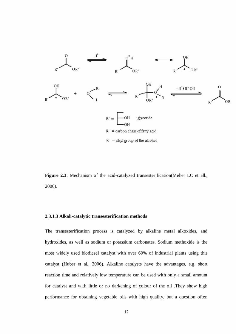
practical reaction times. The mechanism of the acid-catalyzed transesterification of
vegetable oils is shown in Fig. 4. It can be extended to di- and triglycerides. The
protonation of carbonyl group of the ester leads to the carbocation, which after a
nucleophilic attack of the alcohol produces a tetrahedral intermediate. This
intermediate eliminates glycerol to form a new ester and to regenerate the catalyst
(Meher LC et all., 2006 ).
12
Figure 2.3: Mechanism of the acid-catalyzed transesterification(Meher LC et all.,
2006).
2.3.1.3 Alkali-catalytic transesterification methods
The transesterification process is catalyzed by alkaline metal alkoxides, and
hydroxides, as well as sodium or potassium carbonates. Sodium methoxide is the
most widely used biodiesel catalyst with over 60% of industrial plants using this
catalyst (Huber et al., 2006). Alkaline catalysts have the advantages, e.g. short
reaction time and relatively low temperature can be used with only a small amount
for catalyst and with little or no darkening of colour of the oil .They show high
performance for obtaining vegetable oils with high quality, but a question often
13
arises; that is, the oils contain significant amounts of FFAs which cannot be
converted into biodiesels but to a lot of soap. These FFAs react with the alkaline
catalyst to produce soaps that inhibit the separation of the biodiesel, glycerin, and
wash water (Canakci et al., 2003).
In the alkali catalytic methanol transesterification method, the catalyst is dissolved
into methanol by vigorous stirring in a small reactor. The oil is transferred into a
biodiesel reactor and then the catalyst/alcohol mixture is pumped into the oil. The
final mixture is stirred vigorously for 2 h at 340 K in ambient pressure. A successful
transesterification reaction produces two liquid phases: ester and crude glycerol
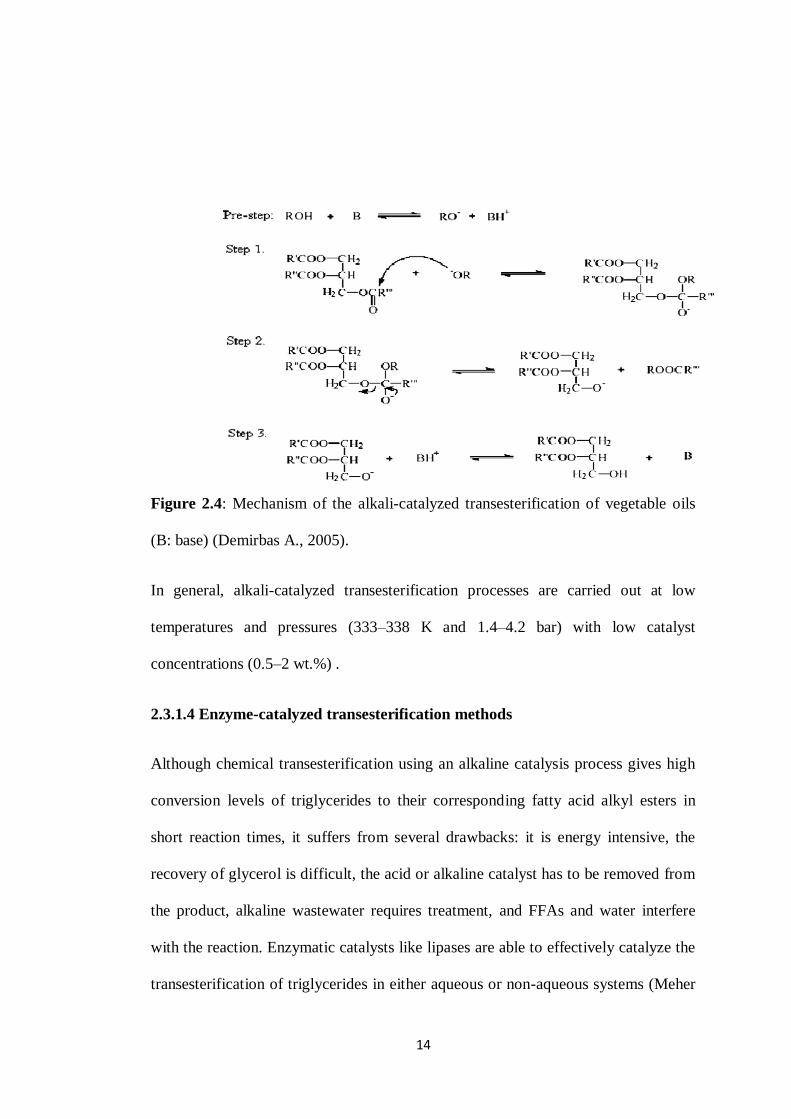
The reaction mechanism for alkali-catalyzed transesterification was formulated as
three steps. The alkali-catalyzed transesterification of vegetable oils proceeds faster
than the acid-catalyzed reaction. The mechanism of the alkali-catalyzed
transesterification of vegetable oils is shown in Fig. 5. The nucleophilic attack of the
alkoxide at the carbonyl group of the triglyceride generates a tetrahedral intermediate
(Fig. 5, Step 1), from which the alkyl ester and the corresponding anion of the
diglyceride are formed (Fig. 5, Step 2). The latter deprotonates the catalyst, thus
regenerating the active species (Fig. 5, Step 3), which is now able to react with a
second molecule of the alcohol, starting another catalytic cycle. Diglycerides and
monoglycerides are converted by the same mechanism to a mixture of alkyl esters
and glycerol (Demirbas., 2005).
14
Figure 2.4: Mechanism of the alkali-catalyzed transesterification of vegetable oils
(B: base) (Demirbas A., 2005).
In general, alkali-catalyzed transesterification processes are carried out at low
temperatures and pressures (333–338 K and 1.4–4.2 bar) with low catalyst
concentrations (0.5–2 wt.%) .
2.3.1.4 Enzyme-catalyzed transesterification methods
Although chemical transesterification using an alkaline catalysis process gives high
conversion levels of triglycerides to their corresponding fatty acid alkyl esters in
short reaction times, it suffers from several drawbacks: it is energy intensive, the
recovery of glycerol is difficult, the acid or alkaline catalyst has to be removed from
the product, alkaline wastewater requires treatment, and FFAs and water interfere
with the reaction. Enzymatic catalysts like lipases are able to effectively catalyze the
transesterification of triglycerides in either aqueous or non-aqueous systems (Meher
15
et al., 2006). In particular, it should be noted that the byproduct, glycerol, can be
easily recovered with simple separation processes. Nevertheless, enzymatic catalysts
are often more expensive than chemical catalysts, so recycling and reusing them is
often a must for commercial viability. Enzyme-catalyzed reactions have the
advantage of reacting at room temperature without producing spent catalysts.
However, enzyme-catalyzed system requires a much longer reaction time than the
other two systems. Alcoholysis of triacylgycerols with a lipase is considered to be
one of the most effective reactions for production of biodiesel. Lipases catalyze the
hydrolysis of triacylgycerols into fatty acids and glycerol, as well as the reactions
that involve synthesis (Karam et al).
The two main categories in which lipase-catalyzed reactions may occur are as
follows (Shah et al., 2003):
(i)Hydrolysis
RCOOR′ + H2O ⟷ RCOOH + R′OH.
Synthesis: Reactions under this category can be further divided:
Esterification
RCOOH + R′OH ⟷ RCOOR′ + H2O
Transesterification: Under certain circumstances, lipases catalyze a number of
transesterification reactions. These reactions can be illustrated by Equation below;
Alcoholysis
RCOOR′ + R′′OH ⟷ RCOOR′′ + R′OH.
Acidolysis
16
RCOOR′ + R′′COOH ⟷ R′′COOR′ + RCOOH
The enzyme reactions are highly specific and chemically clean. The excess alcohol is
reported to be inhibitory to some enzymes and hence a typical strategy is to feed the
alcohol into the reactor in three steps of 1:1 mol ratio each. Generally, these
reactions are very slow, with a three step sequence requiring from 4 to 40 h, or more.
The reaction conditions are modest, from 303 to 313 K
2.3.2 Non-catalytic transesterification methods
There are two basic routes to produce biodiesel by non-catalyzed transesterification,
namely, (i) BIOX co-solvent process and (ii) the supercritical alcohol process.
2.3.2.1 BIOX co-solvent process
Co-solvent options are designed to overcome slow reaction time caused by the
extremely low solubility of the alcohol in the triglyceride phase. One approach that is
nearing commercialization is the BIOX process. This process uses either
tetrahydrofuran (THF) or methyl tert-butyl ether (MTBE) as a co-solvent to generate
a one-phase system. The result is a fast reaction, on the order of 5–0 min, and no
catalyst residues in either the ester or the glycerol phase. The THF co-solvent is
chosen, in part, because it has a boiling point very close to that of methanol. This
system requires a rather low operating temperature, 303 K (Balat M. and Balat H.,
2010).
17
2.3.2.2 Supercritical alcohol transesterification
The transesterification of triglycerides by supercritical methanol, ethanol, propanol
and butanol has proved to be the most promising process. Saka and Kusdiana
proposed that biodiesel fuels may be prepared from vegetable oil via non-catalytic
transesterification with supercritical methanol. Saka and Kusdiana have proposed
that the reactions of rapeseed oil were complete within 240 s at 623 K, 19 MPa, and
molar ratio of methanol to oil at 42. To achieve more moderate reaction conditions,
further effort through the two-step preparation was made Kusdiana and Saka. In this
method, oils/fats are, first, treated in subcritical water for hydrolysis reaction to
produce fatty acids. After hydrolysis, the reaction mixture is separated into oil phase
and water phase by decantation. The oil phase (upper portion) is mainly fatty acids,
while the water phase (lower portion) contains glycerol in water. The separated oil
phase is then mixed with methanol and treated at supercritical condition to produce
methyl esters thorough esterification. After removing unreacted methanol and water
produced in reaction, FAME can be obtained as biodiesel. Methyl esterification of
fatty acids is a major reaction to produce FAME in the two-step supercritical
methanol method, whereas transesterification of triglycerides is a major one in the
conventional alkali- and acid-catalyzed methods. This esterification reaction is,
therefore, an important step for high quality biodiesel fuel production (Minami E,
Saka S., 2006).
18
CHAPTER 3
METHODOLOGY
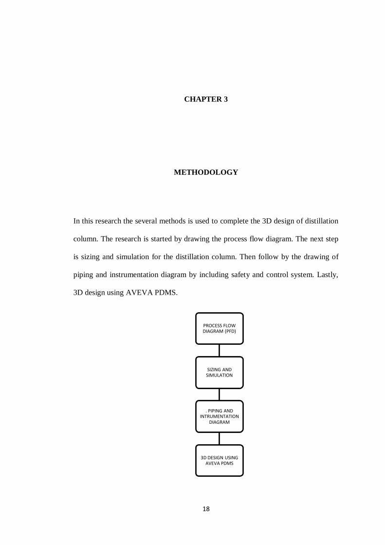
In this research the several methods is used to complete the 3D design of distillation
column. The research is started by drawing the process flow diagram. The next step
is sizing and simulation for the distillation column. Then follow by the drawing of
piping and instrumentation diagram by including safety and control system. Lastly,
3D design using AVEVA PDMS.
PROCESS FLOW DIAGRAM (PFD)
SIZING AND SIMULATION
. PIPING AND INTRUMENTATION
DIAGRAM
3D DESIGN USING AVEVA PDMS