Embed Size (px)
Citation preview
Concepts of Creating
a Geodetic Adjustment
Edward E. Carlson
NOAA, National Geodetic Survey
Pacific Region Geodetic Advisor
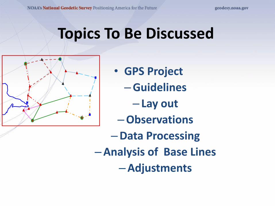
• GPS Project
–Guidelines
– Lay out
–Observations
–Data Processing
–Analysis of Base Lines
–Adjustments
Topics To Be Discussed
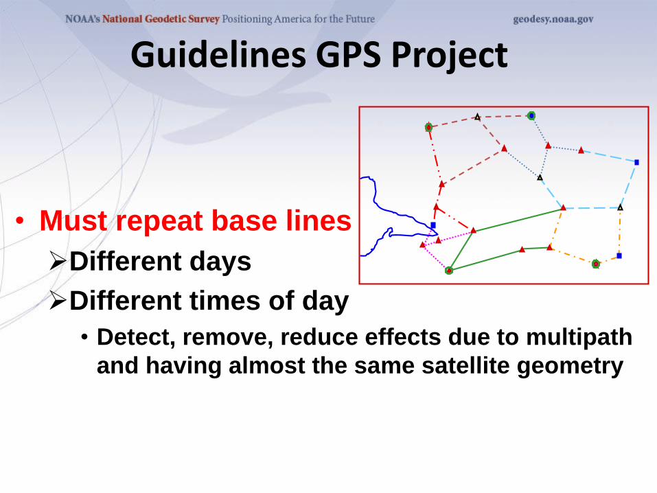
Guidelines GPS Project
• Must repeat base lines
➢Different days
➢Different times of day
• Detect, remove, reduce effects due to multipath
and having almost the same satellite geometry
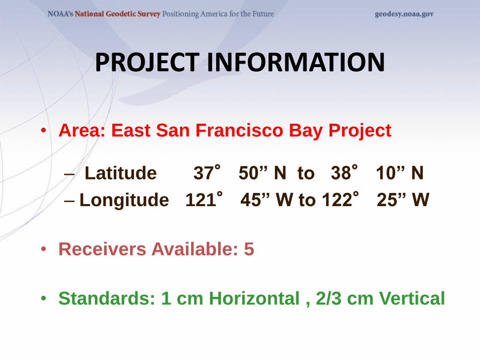
PROJECT INFORMATION
• Area: East San Francisco Bay Project
– Latitude 37° 50” N to 38° 10” N
– Longitude 121° 45” W to 122° 25” W
• Receivers Available: 5
• Standards: 1 cm Horizontal , 2/3 cm Vertical
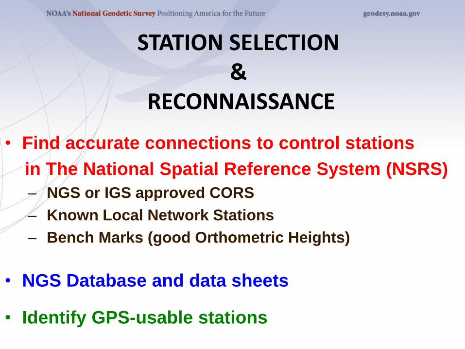
STATION SELECTION &
RECONNAISSANCE
• Find accurate connections to control stations
in The National Spatial Reference System (NSRS)
– NGS or IGS approved CORS
– Known Local Network Stations
– Bench Marks (good Orthometric Heights)
• NGS Database and data sheets
• Identify GPS-usable stations
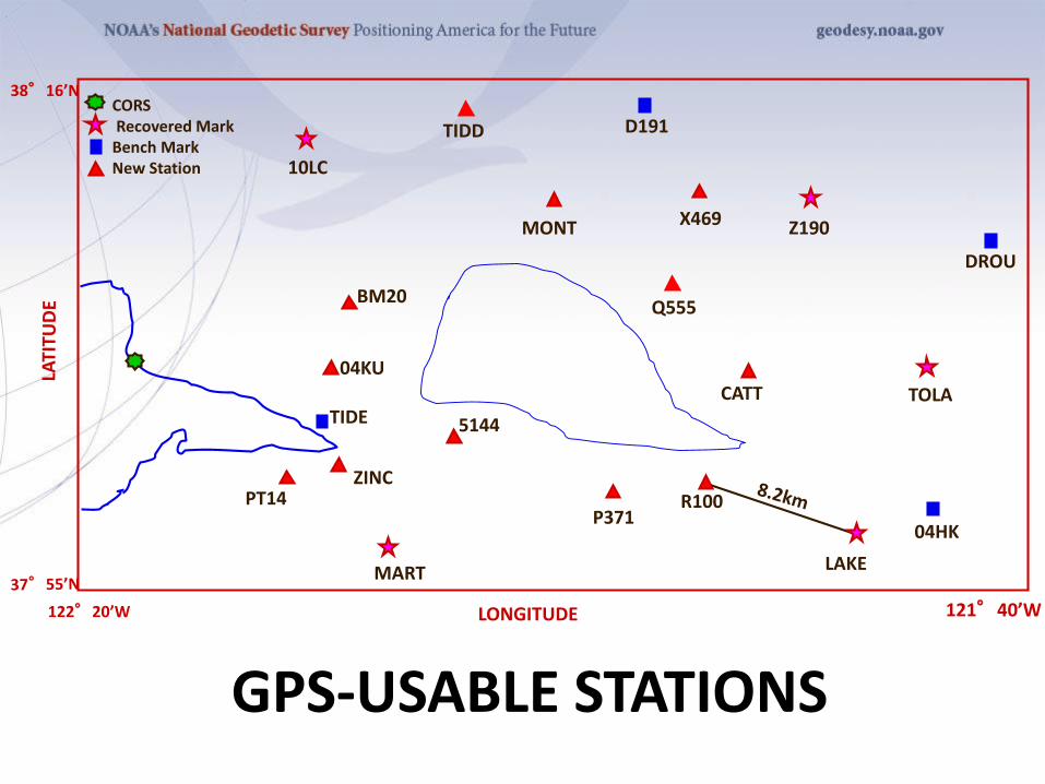
38°16’NCORSRecovered Mark
Bench MarkNew Station
121°40’W122°20’W LONGITUDE
10LC
TIDD D191
MONT X469 Z190
DROU
BM20
04KU
TIDE
ZINCPT14
MART
5144
P371R100
LAKE
04HK
CATT
Q555
TOLA
GPS-USABLE STATIONS
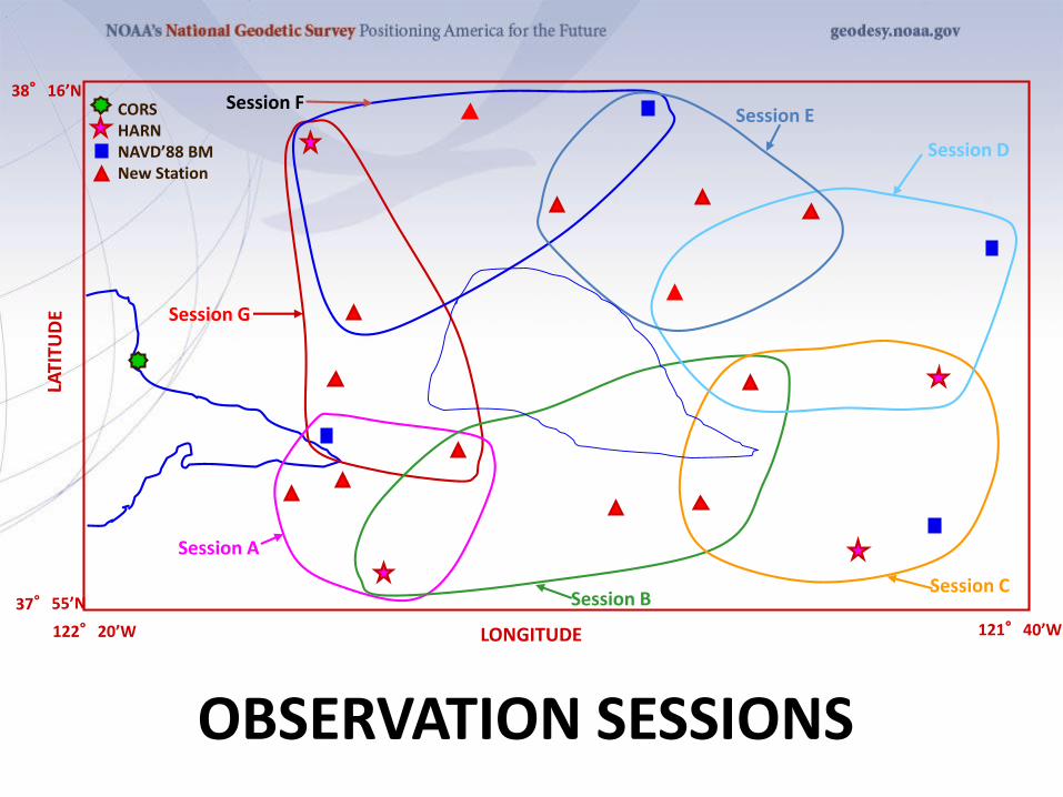
CORSHARNNAVD’88 BMNew Station
121°40’W122°20’W
38°16’N
LONGITUDE
Session A
Session BSession C
Session D
Session ESession F
Session G
OBSERVATION SESSIONS
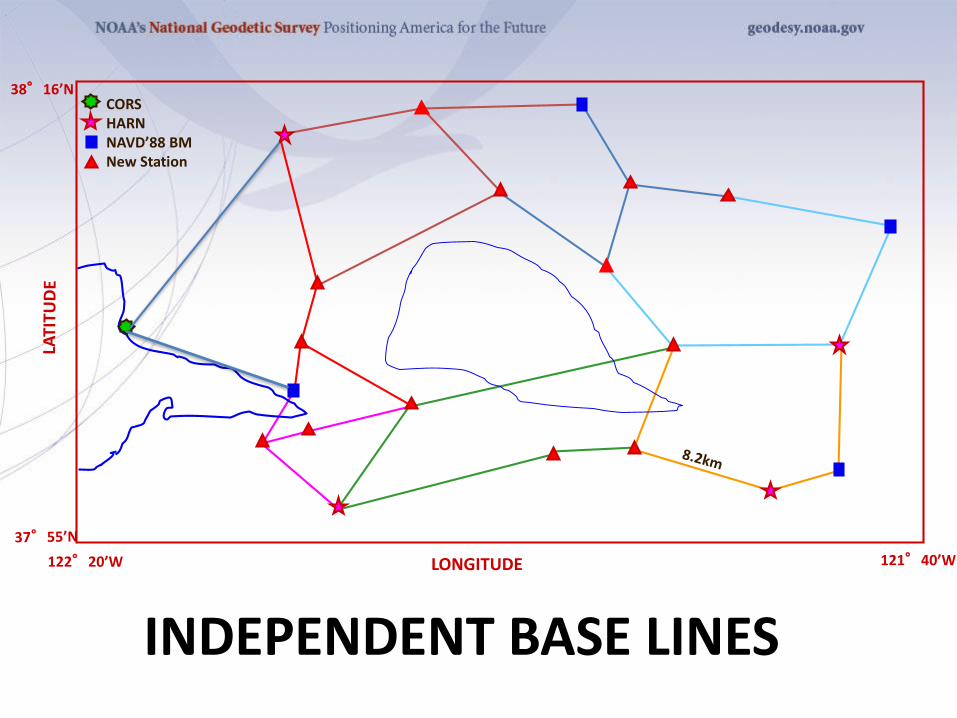
CORSHARNNAVD’88 BMNew Station
121°40’W122°20’W
38°16’N
LONGITUDE
INDEPENDENT BASE LINES
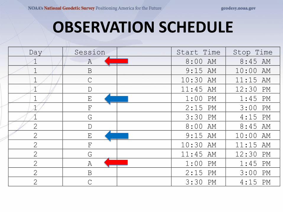
Day Session Start Time Stop Time
1 A 8:00 AM 8:45 AM
1 B 9:15 AM 10:00 AM
1 C 10:30 AM 11:15 AM
1 D 11:45 AM 12:30 PM
1 E 1:00 PM 1:45 PM
1 F 2:15 PM 3:00 PM
1 G 3:30 PM 4:15 PM
2 D 8:00 AM 8:45 AM
2 E 9:15 AM 10:00 AM
2 F 10:30 AM 11:15 AM
2 G 11:45 AM 12:30 PM
2 A 1:00 PM 1:45 PM
2 B 2:15 PM 3:00 PM
2 C 3:30 PM 4:15 PM
OBSERVATION SCHEDULE
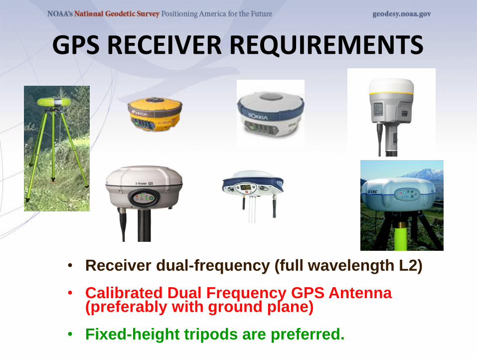
GPS RECEIVER REQUIREMENTS
• Receiver dual-frequency (full wavelength L2)
• Calibrated Dual Frequency GPS Antenna (preferably with ground plane)
• Fixed-height tripods are preferred.
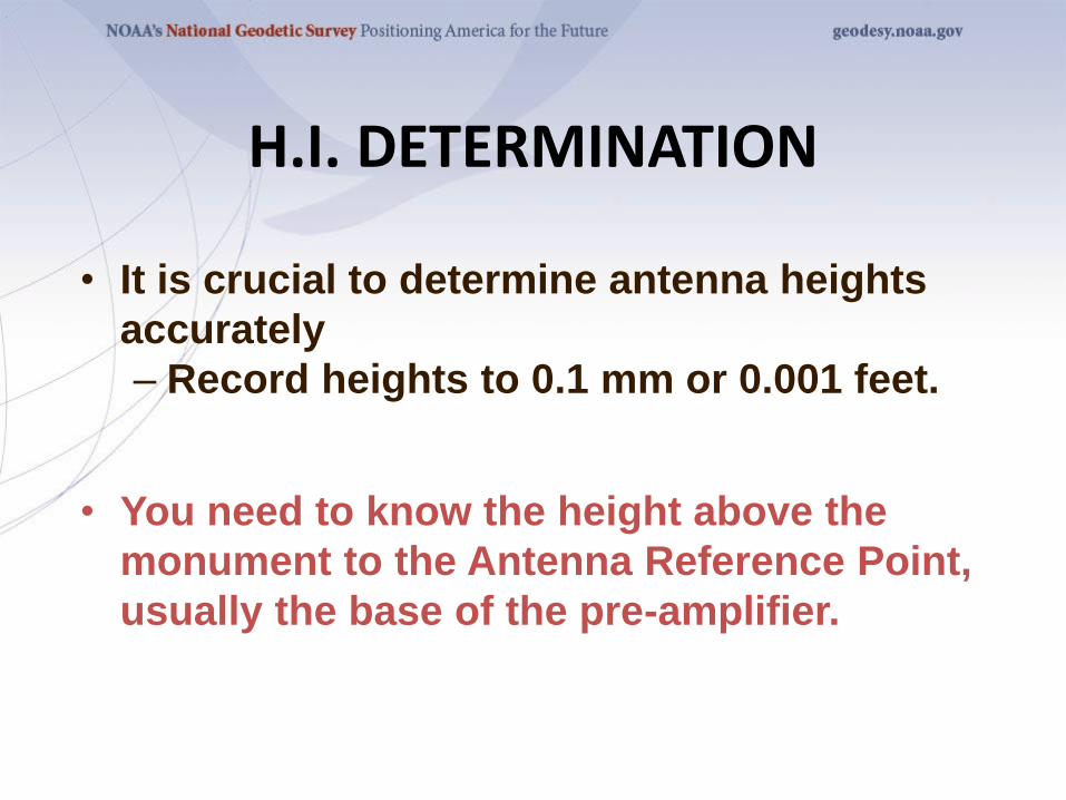
H.I. DETERMINATION
• It is crucial to determine antenna heights
accurately
– Record heights to 0.1 mm or 0.001 feet.
• You need to know the height above the
monument to the Antenna Reference Point,
usually the base of the pre-amplifier.
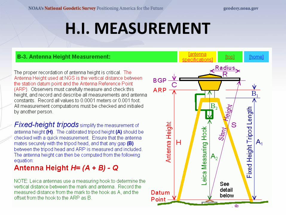
H.I. MEASUREMENT
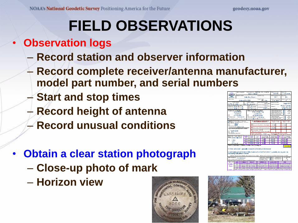
FIELD OBSERVATIONS• Observation logs
– Record station and observer information
– Record complete receiver/antenna manufacturer, model part number, and serial numbers
– Start and stop times
– Record height of antenna
– Record unusual conditions
• Obtain a clear station photograph
– Close-up photo of mark
– Horizon view
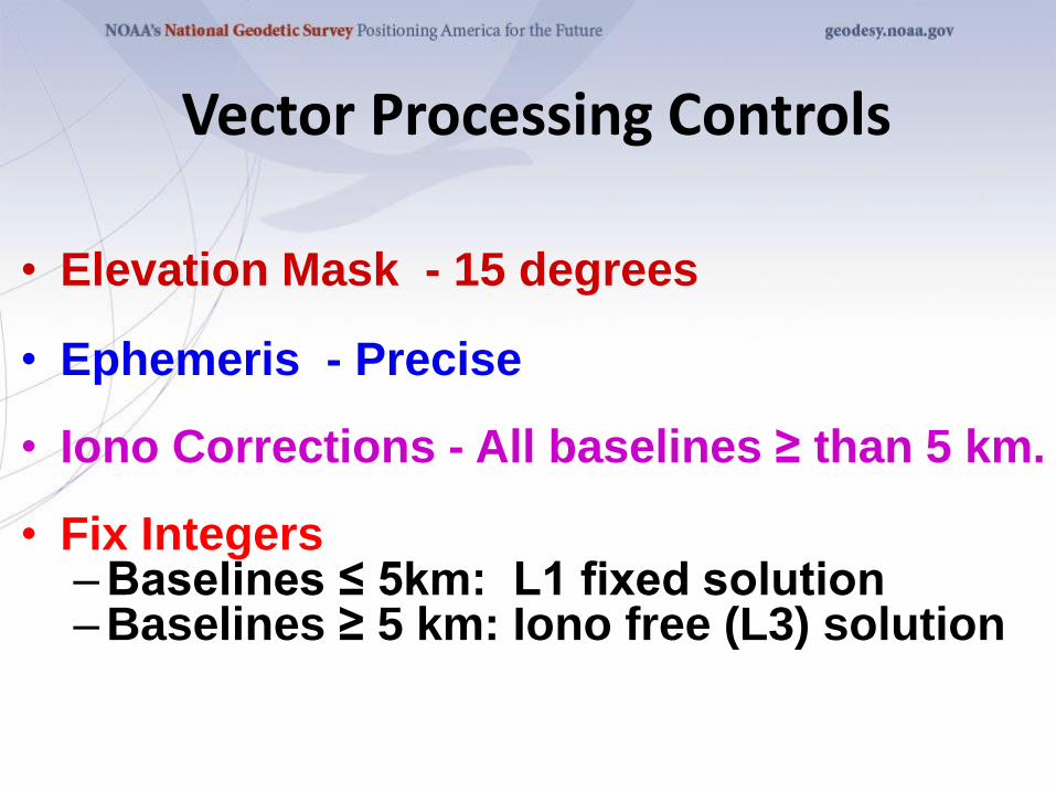
Vector Processing Controls
• Elevation Mask - 15 degrees
• Ephemeris - Precise
• Iono Corrections - All baselines ≥ than 5 km.
• Fix Integers–Baselines ≤ 5km: L1 fixed solution–Baselines ≥ 5 km: Iono free (L3) solution
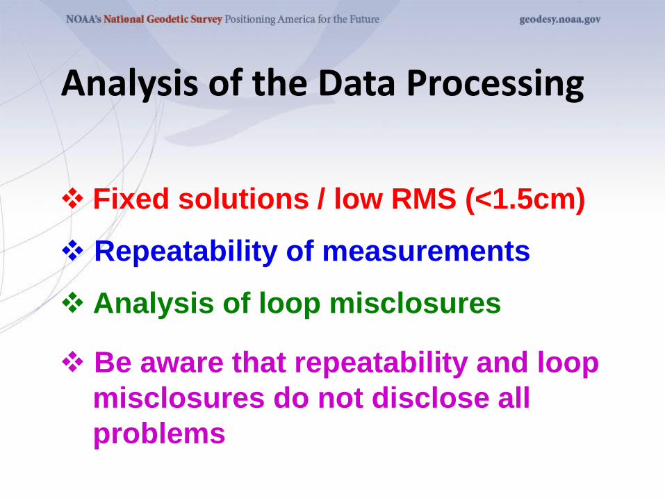
Analysis of the Data Processing
❖ Fixed solutions / low RMS (<1.5cm)
❖ Repeatability of measurements
❖ Analysis of loop misclosures
❖ Be aware that repeatability and loop
misclosures do not disclose all
problems
CORSHARNNAVD’88 BMNew Station
121°40’W122°20’W
38°16’N
LONGITUDE
Primary Base Station
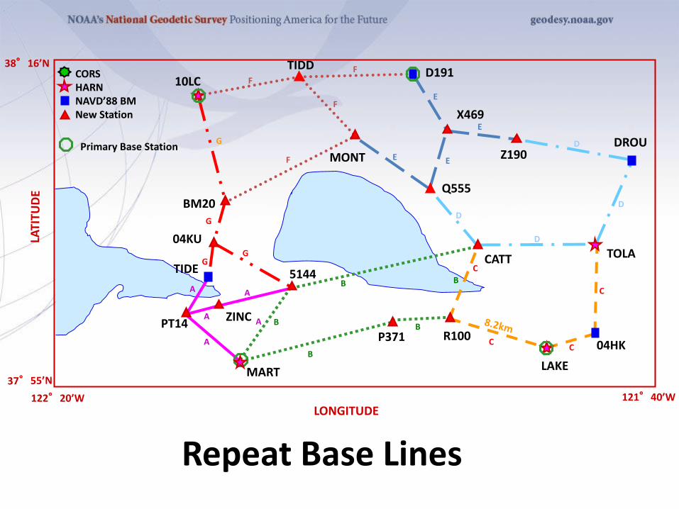
Repeat Base Lines
A
A
A
AB
B
B
B
C
CC
C
D
D
DD
E
E
E
E
FF
F
F
G
G
GG
10LCTIDD
D191
MONT
X469
Z190DROU
BM20
04KU
TIDE
ZINCPT14
MART
5144
P371 R100
LAKE
04HK
CATT
Q555
TOLA
A
B
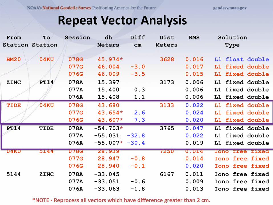
From To Session dh Diff Dist RMS Solution
Station Station Meters cm Meters Type
BM20 04KU 078G 45.974* 3628 0.016 L1 float double
077G 46.004 -3.0 0.017 L1 fixed double
076G 46.009 -3.5 0.015 L1 fixed double
ZINC PT14 078A 15.397 3173 0.006 L1 fixed double
077A 15.400 0.3 0.006 L1 fixed double
076A 15.408 1.1 0.006 L1 fixed double
TIDE 04KU 078G 43.680 3133 0.022 L1 fixed double
077G 43.654* 2.6 0.024 L1 fixed double
076G 43.607* 7.3 0.020 L1 fixed double
PT14 TIDE 078A -54.703* 3765 0.047 L1 fixed double
077A -55.031 -32.8 0.022 L1 fixed double
076A -55.007* -30.4 0.019 L1 fixed double
04KU 5144 078G 28.939 7250 0.014 Iono free fixed
077G 28.947 -0.8 0.014 Iono free fixed
076G 28.940 -0.1 0.020 Iono free fixed
5144 ZINC 078A -33.045 6167 0.011 Iono free fixed
077A -33.051 -0.6 0.009 Iono free fixed
076A -33.063 -1.8 0.013 Iono free fixed
Repeat Vector Analysis
*NOTE - Reprocess all vectors which have difference greater than 2 cm.
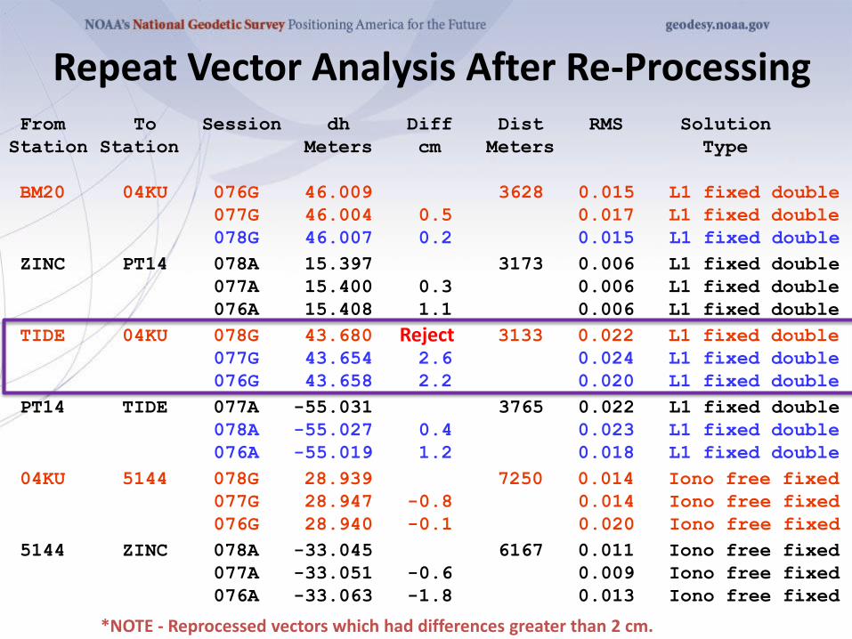
From To Session dh Diff Dist RMS Solution
Station Station Meters cm Meters Type
BM20 04KU 076G 46.009 3628 0.015 L1 fixed double
077G 46.004 0.5 0.017 L1 fixed double
078G 46.007 0.2 0.015 L1 fixed double
ZINC PT14 078A 15.397 3173 0.006 L1 fixed double
077A 15.400 0.3 0.006 L1 fixed double
076A 15.408 1.1 0.006 L1 fixed double
TIDE 04KU 078G 43.680 3133 0.022 L1 fixed double
077G 43.654 2.6 0.024 L1 fixed double
076G 43.658 2.2 0.020 L1 fixed double
PT14 TIDE 077A -55.031 3765 0.022 L1 fixed double
078A -55.027 0.4 0.023 L1 fixed double
076A -55.019 1.2 0.018 L1 fixed double
04KU 5144 078G 28.939 7250 0.014 Iono free fixed
077G 28.947 -0.8 0.014 Iono free fixed
076G 28.940 -0.1 0.020 Iono free fixed
5144 ZINC 078A -33.045 6167 0.011 Iono free fixed
077A -33.051 -0.6 0.009 Iono free fixed
076A -33.063 -1.8 0.013 Iono free fixed
*NOTE - Reprocessed vectors which had differences greater than 2 cm.
Repeat Vector Analysis After Re-Processing
Reject
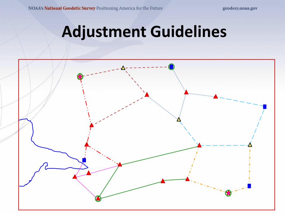
Adjustment Guidelines
Least Squares Adjustments
• The adjustment minimizes the effects of
random errors
• A least squares adjustment computes a
single network solution, even with
redundant vectors
• Least squares will highlight blunders and
large errors
• It will provide estimates on the precision
of the coordinates for the stations
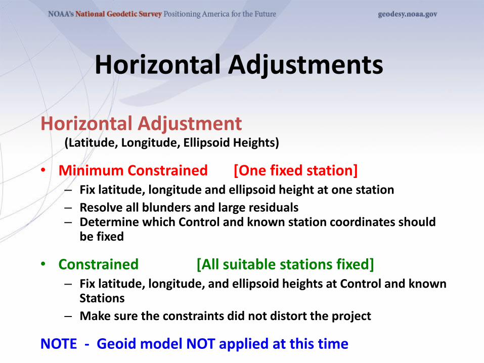
Horizontal Adjustments
Horizontal Adjustment(Latitude, Longitude, Ellipsoid Heights)
• Minimum Constrained [One fixed station]– Fix latitude, longitude and ellipsoid height at one station
– Resolve all blunders and large residuals– Determine which Control and known station coordinates should
be fixed
• Constrained [All suitable stations fixed]– Fix latitude, longitude, and ellipsoid heights at Control and known
Stations
– Make sure the constraints did not distort the project
NOTE - Geoid model NOT applied at this time
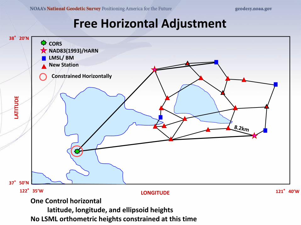
Free Horizontal Adjustment
CORSNAD83(1993)/HARNLMSL/ BMNew Station
121°40’W122°35’W
38°20’N
LONGITUDE
One Control horizontallatitude, longitude, and ellipsoid heights
No LSML orthometric heights constrained at this time
Constrained Horizontally
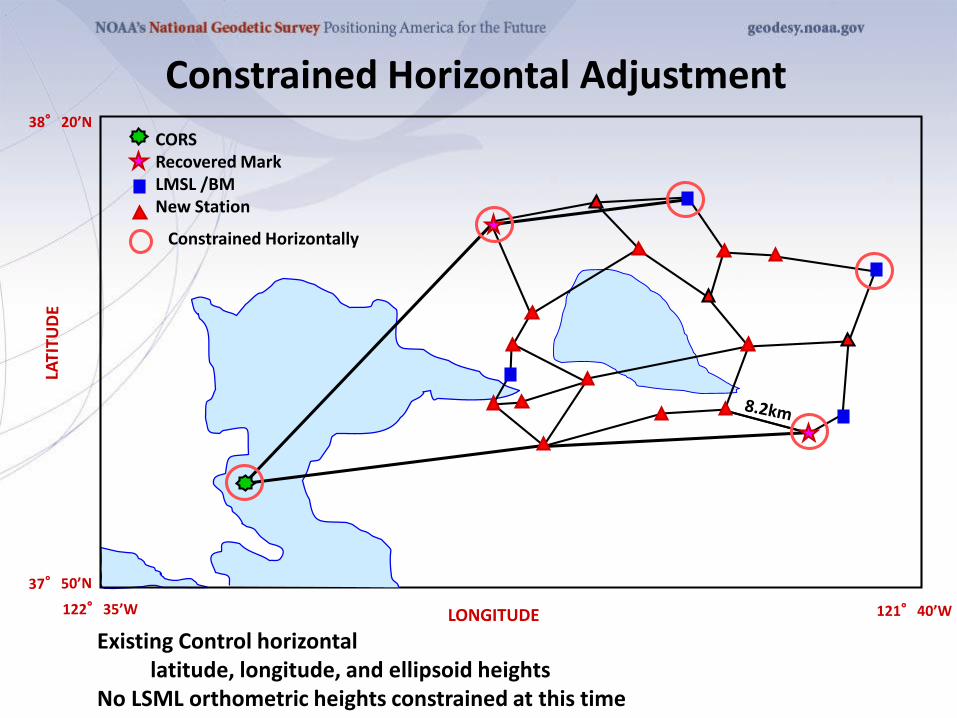
Constrained Horizontal Adjustment
CORSRecovered MarkLMSL /BMNew Station
121°40’W122°35’W
38°20’N
LONGITUDE
Existing Control horizontallatitude, longitude, and ellipsoid heights
No LSML orthometric heights constrained at this time
Constrained Horizontally
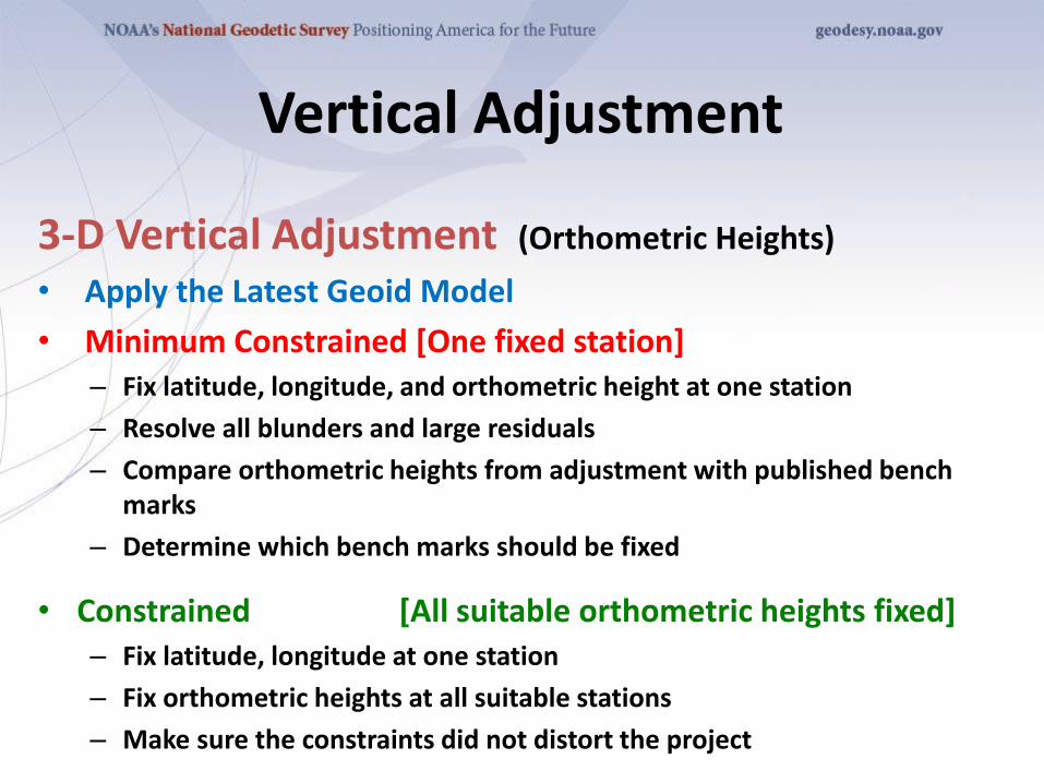
3-D Vertical Adjustment (Orthometric Heights)
• Apply the Latest Geoid Model
• Minimum Constrained [One fixed station]– Fix latitude, longitude, and orthometric height at one station
– Resolve all blunders and large residuals
– Compare orthometric heights from adjustment with published bench marks
– Determine which bench marks should be fixed
• Constrained [All suitable orthometric heights fixed]– Fix latitude, longitude at one station
– Fix orthometric heights at all suitable stations
– Make sure the constraints did not distort the project
Vertical Adjustment
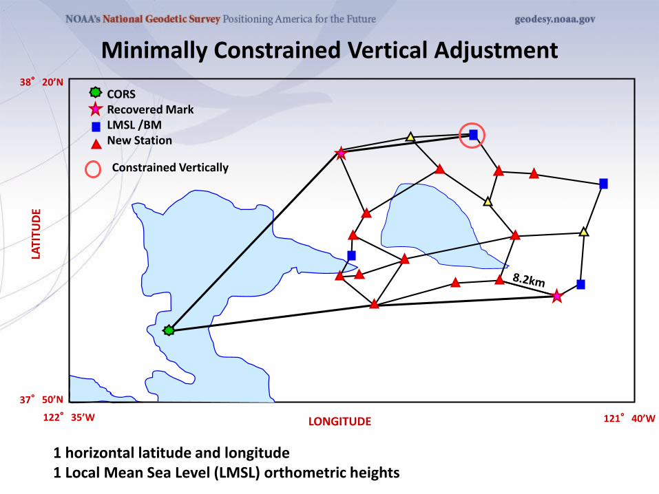
Minimally Constrained Vertical Adjustment
1 horizontal latitude and longitude1 Local Mean Sea Level (LMSL) orthometric heights
CORSRecovered MarkLMSL /BMNew Station
121°40’W122°35’W
38°20’N
LONGITUDE
Constrained Vertically
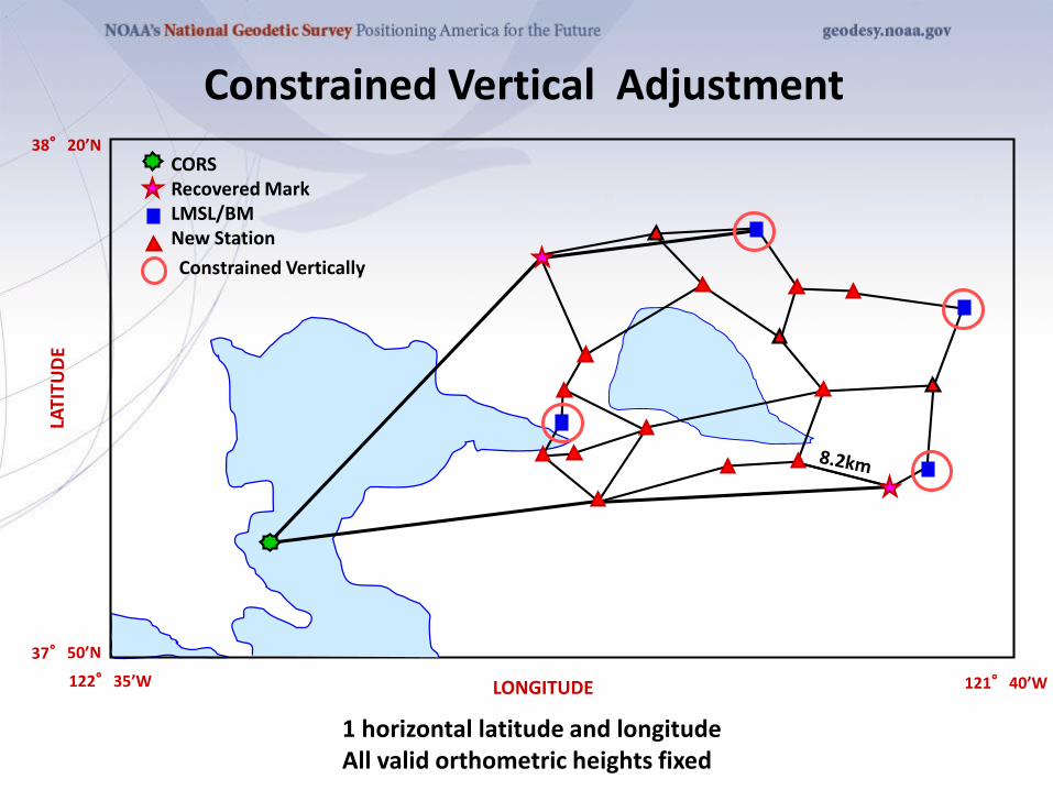
Constrained Vertical Adjustment
CORSRecovered MarkLMSL/BMNew Station
121°40’W122°35’W
38°20’N
LONGITUDE
1 horizontal latitude and longitudeAll valid orthometric heights fixed
Constrained Vertically
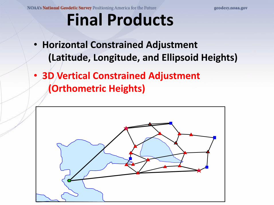
Final Products • Horizontal Constrained Adjustment
(Latitude, Longitude, and Ellipsoid Heights)
• 3D Vertical Constrained Adjustment(Orthometric Heights)
Summary
• Mistakes and systematic errors must be removed before the adjustment
• A least squares adjustment handles random errors and provides a single solution
• The Minimally Constrained adjustment checks the internal consistency of the network
• The Constrained adjustment checks the existing control and references the network to the datum
• The vertical adjustment estimates GPS-derived Orthometric heights
Mahalo - Questions ????


![Large-Scale Geodetic Least-Squares Adjustment by ... · This ten-year project by the U.S. National Geodetic Survey ... Qtb=[ ;], where c is an n ... The final section contains](https://img.pdfslide.us/doc/110x75/5ae941d97f8b9ab24d8bd984/large-scale-geodetic-least-squares-adjustment-by-ten-year-project-by-the-us.jpg)