Embed Size (px)
Citation preview

S P I E P r o c e e d i n g 2 0 0 1
Concepts in dosimetry related to laser safety and optical radiation hazard evaluation Karl Schulmeister
Please register to receive our Laser, LED & Lamp Safety NEWSLETTER (about 4 times a year) with information on new downloads:
http://laser-led-lamp-safety.seibersdorf-laboratories.at/newsletter This paper can be downloaded from http://laser-led-lamp-safety.seibersdorf-laboratories.at Karl Schulmeister, “Concepts in dosimetry related to laser safety and optical radiation hazard evaluation”, Laser and Noncoherent Light Ocular Effects: Epidemiology, Prevention, and Treatment, Bruce E. Stuck, Michael Belkin, Editors, Proc. SPIE Vol. 4246 (2001), doi:10.1117/12.426709 Copyright 2001 Society of Photo-Optical Instrumentation Engineers. One print or electronic copy may be made for personal use only. Systematic electronic or print reproduction and distribution, duplication of any material in this paper for a fee or for commercial purposes, or modification of the content of the paper are prohibited.

PROGRESS IN BIOMEDICAL OPTICS AND IMAGING Vol. 2, No.3
ISSN 1605-7422
Laser and Noncoherent Light Ocular Effects: Epidemiology, Prevention, and Treatment Ed. Bruce E. Stuck Michael Belkin Chairs/Editors 22 January 2001 San Jose, USA
Sponsored by U.S. Air Force Office of Scientific Research SPIE – The International Society for Optical Engineering
Proceedings of SPIE Volume 4246

Laser and Noncoherent Light Ocular Effects: Epidemiology, Prevention, and Treatment 104 Bruce E. Stuck, Michael Belkin, Editors, Proceedings of SPIE Vol. 4246 (2001) © 2001 SPIE · 1605-7422/01/$15.00
Concepts in dosimetry related to laser safety and optical radiation hazard evaluation
Karl Schulmeister§
Austrian Research Centers Seibersdorf, A-2444 Seibersdorf, Austria
ABSTRACT Concepts in dosimetry pertinent to hazard evaluation of optical radiation and specifically laser radiation are discussed. The basic units of power, energy, irradiance, exposure and radiance will be reviewed, as well as the relation of retinal exposures and experimental data given as intra-ocular energy to exposure limits specified in exposure at the cornea or time integrated radiance. Averaging apertures and field of views are specified with the exposure limits to be used when exposure values are measured or calculated which in turn are compared to exposure limits for laser radiation or broadband optical radiation. The size of the averaging aperture for irradiance measurements or the size of the averaging field of view for radiance measurements is closely linked to biophysical effects and dimensions such as the diameter of the pupil of the eye or the angular extent of eye movements. In some cases, the specified size of the averaging aperture and FOV result in measured irradiance and radiance values, which are much smaller than the real physical values. In the latest revision of the international laser safety standard, IEC 60825-1, and in the revised ICNIRP laser limits, blue light limits are split from the thermal limits and are given in irradiance, specifying corresponding measurement criteria for the measurement FOV. The derivation of the irradiance limit from the basic radiance limit as it is specified for the broadband blue light hazard (for instance by ACGIH and ICNIRP) can be understood on the basis of the specification for the measurement FOV. Keywords: dosimetry, radiometry, laser safety, optical radiation, hazard evaluation, exposure limit, Maximum Permissible Exposure, averaging aperture, field of view, photochemical retinal limit
1. INTRODUCTION Exposure limits for laser radiation and broadband optical radiation are defined on the basis of animal experiments and on injury data, and the levels are set so that adverse effects or injuries are prevented if the exposure level is below the exposure limit (EL) for a given exposure duration and wavelength. As the optical and thermal properties of the skin and the eye are different, the ELs for the eye and the skin differ, especially in the retinal hazard wavelength region*. Consequently there is a set of ELs for ocular exposure and another one for the skin. The ELs depend on the exposure duration and the laser wavelength and may also depend on the size of the source-image on the retina. This image size is expressed as angular subtense of the apparent source and will be discussed in the body of the paper. In order to evaluate the potential hazard of exposure to optical radiation, the level of exposure at a given location and for a given exposure scenario, including the exposure duration, need to be assessed, and this value is then compared to the EL for the given exposure duration, wavelength and, if applicable, the angular subtense of the apparent source. This process of hazard evaluation, i.e. of assessing (calculating or measuring) the level exposure on the one hand and comparing this value with the appropriate exposure limit on the other hand is commonplace in health physics. For optical radiation hazard assessments, it is particularly important to keep this concept in mind in order to understand the close link of the measurement and the EL, which is somewhat unique for optical radiation, as will be elaborated in this paper. Wording such as “the EL is measured”, can lead to confusion, as it is the exposure which is to be measured (with a certain averaging aperture and field of view), and this exposure value is consequently to be compared to the EL. The internationally accepted committee which defines exposure limits for laser radiation and broadband optical radiation is the International Commission for Non-Ionizing Radiation Protection, which publishes the respective guidelines in the
§ [email protected]; phone +43 50550 2533; fax +43 50550 2502; http://www.arcs.ac.at/G/GS * The retinal hazard region is the wavelength range between 400 nm and 1400 nm, where the radiation is focused onto the retina of the eye.

Proc. SPIE Vol. 4246 105
Health Physics journal1,2,3. A number of national and international standards adopted these exposure limits for specific purposes, such as the international laser safety standard4 IEC 60825-1.2, which is mainly a product requirement standard, but also features a section on user guidelines, or the American National Standard5 ANSI Z136.1, a laser user standard. In both documents, the exposure limits are called maximum permissible exposure limits, MPEs, but they are identical to the EL as published by ICNIRP. Regarding broadband radiation, several document were developed and published in recent years, which made use of the exposure limits as specified by ICNIRP: for lamp safety, the northern American6 IESNA RP-27 required practice series for lamp manufacturers, a standard developed by the international lighting committee7 CIE, with the aim to serve as basis for an international lamp product safety standard, and a technical report of the International Electrotechnical Committee8, IEC 60825-9, where the goal was to summarize the ICNIRP exposure limits for incoherent broadband radiation. Above documents also specify the measurement requirements which need to be observed when assessing the level of exposure. The goal of this paper is to review the measurement requirements in terms of what could be called “geometrical aspects” of the measurement, i.e. mainly the averaging aperture and the field of view, and to discuss the origin and background to these requirements. This review concentrates on the hazard evaluation of a given exposure szenario of the general public or in the work place, in contrast to product safety requirements, where the emission of a product has to be tested against specified requirements. However, much of the discussion is also applicable to the classification of laser products following the concept of allowable emission limits, AEL, as for instance used in IEC 60825-1 or ANSI Z136.1, since the AELs of Class 1 and Class 2 are directly derived from the exposure limits for the eye by multiplication with the area of the averaging aperture.
2. OVERVIEW OF QUANTITIES AND UNITS The quantities and units relevant for the definition of exposure limits and for measurements and hazard evaluation of exposure to laser radiation and optical radiation are summarized in Table 1. Table 1. Quantities and units used to express exposure limits and to measure and evaluate exposures to laser radiation and broadband optical radiation. The letters are the usual symbols used for the respective quantities, as for instance used in IEC 60825-1 and ANSI Z136.1. No specific letter is assigned for the time integrated radiance, and the symbol L⋅t is used in this paper. It is noted that the units given in the table are the basic SI units, and the usual derived units such as cm² and mW are often used in practice. Power P Unit: Watt (W)
Irradiance E Unit:
2mW
Radiance L Unit:
srmW2
Energy Q Unit: Joule (J)
Radiant exposure H Unit:
2mJ
Time Integrated Radiance L⋅t Unit:
srmJ2
Comment: Basic Quantity Comment: Averaging over aperture area Comment: Averaging over aperture area and measurement field of view
2.1 Temporal integration to obtain “dose” The relationship between the quantities of the first line of Table 1, which could be collectively addressed as “power quantities”, with the quantities in the second line, which could be called “energy quantities”, is in terms of the quantity “time”, as energy equals power multiplied by time. For laser safety and hazard assessment of optical radiation, “time” can have the meaning of exposure duration or pulse duration. The power quantities are usually used for quantification of continuous sources and exposures, however, they can also be used in terms of maximum power levels of pulses, especially for ultrashort laser pulses, where some ELs are given in units of W/m². The energy quantities are usually used for quantifying the exposure level** and exposure limit for pulses. However, “energy quantities” are also used for hazard assessment to prevent photochemical damage of the skin or the eye. It is typical for photochemical interaction, that the effect is additive over some duration, which could be called integration duration. For photochemical damage of the eye and the skin by ultraviolet radiation, this integration duration is 8 hours, for photochemical damage of the retina by blue light, the integration duration is 10,000 s, i.e. 2 hours and 47 minutes). Therefore, exposure limits for photochemical damage are
** In this paper, the term “exposure level” is used as general description for the quantity which is assessed for a given exposure situation and which is consequently compared to the exposure limit. It is used as a “catch all” term to represent all relevant quantities as summarized in table 1, including spectral derivatives. Although “intensity” in the everyday use has a corresponding meaning, in optical radiometry it is assigned to the quantity with dimensions power per solid angle (units: W/sr) and is therefore not used in this text in the broad general meaning.

106 Proc. SPIE Vol. 4246
specified as “energy quantity”, and the sum of all individual exposures in the sense of a total “dose” need to be compared to the exposure limit. For the case of a constant continuous exposure, the energy quantity is simply obtained by multiplication of the power quantity with the exposure duration. For continuous exposure with varying irradiance or radiance level, the corresponding energy quantity of the exposure is determined by temporal integration over the required integration duration. The main scope of the paper is to review “geometrical aspects” of the measurement setup and relationship of the quantities as given in table 1 in horizontal direction, and these are the same for power and energy quantities. Consequently, in the remainder of the paper, the deliberations apply to both power and energy quantities, even if it is only referred to one of them. 2.2 Broadband radiation, spectral quantities For laser radiation, where only exposure to discrete wavelengths is an issue, any wavelength dependence of the “effectiveness” of a given level of exposure to produce a lesion, can simply be accounted for in the definition of the exposure limits. For exposure to broadband incoherent radiation, the wavelength dependence is accounted for by action spectra, s(λ), which are used to weigh a given (measured) spectral irradiance, Eλ(λ), measured in units of W m-2 nm-1 (or spectral radiance, measured in units of W m-2 sr-1 nm-1) in order to produce an “effective” irradiance, Eeff (or radiance) by integration over the wavelength, as is expressed by the equation
∫ ⋅= λλλλ dsEEeff )()(
In practice, the spectral irradiance or spectral radiance is measured with spectroradiometers, and the effective irradiance or effective radiance is subsequently calculated numerically. Alternatively, the effective irradiance or radiance can be directly measured with integrating broadband hazard-meters, which feature a spectral sensitivity that mimics the desired action spectrum. The principle of temporal integration of the exposure when the exposure limit is given in energy quantities, as described above, and the geometrical relationships for the measurement as described in the following sections of the paper, apply to spectral quantities in the same way as for non-spectral quantities. Regarding the diameter of the averaging aperture, however, there are differences between the hazard evaluation of broadband radiation in comparison to laser radiation, which will be discussed below.
3. BASIC RADIOMETRIC CONCEPTS 3.1 Irradiance and radiant exposure – averaging over aperture The text of this paragraph only refers to irradiance, however the dosimetry concept discussed also applies to radiant exposure. For radiation which is absorbed by the surface, irradiance is the appropriate quantity to express the “level of exposure”. Irradiance is defined as incident power divided by the area over which the irradiance is determined. If the area to which irradiance is related to becomes infinitesimally small, the irradiance equals the local physical irradiance. For finite areas, the determined irradiance will represent a value averaged over that area. This concept is explained on the basis of the typical practical measurement procedure: a laser radiometer is typically calibrated to measure radiant power or energy incident on the detector with given sensitive area***. The sensitive area can also be reduced by an aperture of a given size. In the following, circular apertures or sensitive areas of the detector are assumed and both are generally referred to as aperture. The irradiance is determined by dividing the power as measured with the radiometer by the area of the aperture. If the irradiance profile incident on the detector is not spatially constant over the detector or aperture area, then the resulting irradiance value represents an value averaged over the area of the aperture. An example plot of a non-constant irradiance profile and the average value is schematically shown in figure 1. The “averaging” can be conceptualized as “spreading” the total power on the detector over the aperture area. The aperture area, i.e. measurement area, can also be considered as the smallest spatial resolution with which the irradiance can be determined and hotspots in the irradiance profile smaller than the aperture area can not be detected. If the irradiance profile is spatially constant over a given area, then the averaged irradiance is equal to the true physical irradiance value. If the aperture area is decreased, the measured power will decrease correspondingly and the resulting irradiance value remains constant. In the field of laser safety and for hazard evaluation of broadband optical radiation, specific averaging apertures are specified which are related to biological parameters such as pupil size and eye-movements. In some cases, the specified size of the averaging aperture result in measured irradiance values, which are much smaller than the real physical values.
*** Some laser radiometers and most spectroradiometers are calibrated to measure irradiance directly. It should be kept in mind that the irradiance value measured is averaged over the sensitive area of the detector for which the calibration has be performed.

Proc. SPIE Vol. 4246 107
However, for hazard evaluations, it is these biologically effective values, which have to be compared to the respective exposure limits for optical radiation, as will be discussed further below.
Irr
adia
nce
(W/ m
²)
Average Irradiance
Hot-spot
Fig. 1. Example of an inhomogeneous irradiance profile across a detector surface and the corresponding averaged value. If the true irradiance profile is to be determined,
then the measurement aperture would have to be correspondingly small. For completeness it is noted that sometimes power- and energy density are also used instead of irradiance or radiant exposure. Following the document DIN xx, power and energy density should be used to denote power and energy relative to a volume, i.e. they are measured with units of W/m³ and J/m³. It is also noted that for optical radiation propagation in scattering media radiant exposure, radiant exposure has a different concept than fluence, as fluence is defined as energy per area passing through a given area from either side of the area, i.e. it not only includes the exposure of the surface to the direct laser radiation, but also includes exposure with radiation scattered within the tissue. 3.2 Beam diameter For the determination of the irradiance to be compared to exposure limits for laser radiation and broadband radiation, it is not necessary to determine the diameter of the irradiated area or the beam diameter, as the irradiance is averaged over a specified area. However, as basis for the following discussion on retinal image diameter and irradiated spot areas for the cornea or the skin, the definition of beam diameter is reviewed. Usually the term “beam” is used for a well defined collimated beam of optical radiation, i.e. a beam with relatively small divergence, such as a laser beam or a searchlight beam. Here, the term beam diameter is used more broadly to denote the diameter of the irradiated area at a given surface. For a top hat spatial beam profile, the beam diameter is intrinsic in the profile. However, for more general beams, the irradiance will gradually decrease and to define the beam diameter as the diameter where the irradiance actually reaches would not be practical. Therefore, the beam diameter is usually defined as the minimum diameter of the circular area within which a certain percentage of the total power is contained. In laser safety and safety of optical radiation, this percentage is 68 %, which for a Gaussian beam profile corresponds to a that local irradiance at the diameter which is a factor of 1/e = 0.368 from the maximum irradiance of the center of the beam, as is schematically depicted in figure 2.
Emax *1/e
Emax *1/e²
Emax
D1/e
D1/e²
Fig. 2. Concept of beam diameter specified at the 1/e points of a Gaussian irradiance profile,
as usual for laser safety purposes, and at the 1/e² points, as usual for technical and engineering purposes. For technical laser beam specifications, a beam diameter at the 1/e² point is most often used, which results in a beam diameter which for a Gaussian beam which is a factor of √2 larger than the 1/e diameter, and the area is a factor 2 larger. The 1/e definition is used in laser safety, as for this diameter, when the irradiance is obtained by dividing the total beam power by the corresponding area (for instance for simple hazard calculations) is equal to the maximum irradiance at the

108 Proc. SPIE Vol. 4246
beam center. If a larger area is used for the determination of the irradiance to be compared to the exposure limit, then the hazard for exposure to the center of the beam is underestimated. 3.3 Imaging onto the retina, angular subtense of apparent source When the eye is exposed to radiation with wavelengths for which the ocular media are transparent, then the radiation is focused by the cornea and the lens onto the retina****. For a characterization of the hazard, the irradiance on the retina is relevant, for which the power or energy and the irradiated area on the retina needs to be quantified. The geometric extent of the irradiated area on the retina is either characterized by the diameter of the irradiated area on the retina, or by the angular subtense subtended by the source at the location of the cornea. If the eye is assumed to be resting in respect to a source, the diameter of the image on the retina dr, in µm, can be related very easily to the angular subtense of the source α in mrad (see Fig. 3) by using the standardised focal length of the eye of 17 mm: dr = α ⋅ 17
α
Fig. 3. The angular subtense of the source is directly related to the size of the image on the retina.
The angular subtense is usually measured in radian, (or milliradian, mrad) which is defined as the ratio of the extent of the source to the distance to the source: a source with dimensions of 1 mm and is located at a distance of 1 m from the eye subtends a plane angle of 1 mrad. Due to the physical limitations of the imaging process in the eye, the minimal angular subtense of the image or spot-size on the retina, termed αmin, is about 1.7 mrad, which is equivalent to a spot size on the retina of about 25 - 30 µm. Such a minimal spot size can be realised either by a very small or distant source or by a well collimated laser beam, which, due to the parallel rays, is perceived as originating at a great distance from the viewer. An apparent source with angular subtense smaller than 1.5 mrad is usually referred to as small source, sources larger than this are referred to as extended sources. The term apparent source is a general term and also includes sources where radiation is projected by collimating optics, and the source subtense and location as perceived by the eye when looking at the source does not correspond to the subtense and location of the real physical source. For a source such as a lamp for which the radiation is collimated by lenses, or a laser which produces a collimated beam, the apparent source lies behind the physical source of the radiation, and it lies further back the better collimated the radiation is. This can be understood on the basis of the angle of the rays entering the eye: parallel rays, such as those coming from a distant star, produce a point image on the retina, which is perceived as a small source originating from a long distance. The location of the apparent source can be inferred by following the direction of the rays to where they would intersect. The characterization and measurement of the location and subtense of the apparent source is not in the scope of this review. 3.4 Field-of-view of the detector Besides the aperture area of the detector, the field-of-view, FOV, is the second geometric property of relevance for the measurement of optical radiation. In simple terms, the FOV is the part of space, quantified as angle, which is “seen” by the detector, or from which the detector (or the input optics) receives radiation. The FOV can be specified as solid angle (i.e. a ”two-dimensional” angle), with the unit of steradian and the symbol for the unit of sr. The solid angle of 1 sr is defined as the solid angle which is subtended by an area of 1 m² at a distance of 1 m away from the area, which can also account for a non-circular FOV. In laser safety and hazard analysis of optical radiation, a circular FOV is assumed, and the plane angle, measured in units of radian (or more often mrad) is often used to characterise the FOV. The plane angle ω of a circular object can be converted to a solid angle Ω by the approximation for small angles, Ω = (π/4) ω². **** It is pointed out that the refraction at the air-cornea surface of the eye is responsible for most of the refractive power of the eye, while the lens of the eye is responsible for fine adjustment between accommodation of the eye to a source in infinity to a source very close to the eye.

Proc. SPIE Vol. 4246 109
The term angle of acceptance is also often used instead of the term FOV, more often for the definition as plane angle than for the solid angle. In ANSI Z136.1, the term cone angle is also used. Often a tube, also called Gershun tube, is used to limit the field of view (FOV) of a detector9. However, as is depicted schematically in Fig. 4, this does not result in a well defined FOV, as different points on the surface of the detector have a different direction and size of FOV and the resulting total FOV of the detector has a central part from which the whole detector surface receives radiation, and an outer part from which only the outer parts of the detector receive radiation.
Det
ecto
rA
rea
Tube
Fig. 4. Using a tube with the detector to limit the field of view results in a central field of view
and outer areas of the detector which have a different field of view. A well defined FOV can be obtained by either of two set-ups, which are depicted in Fig. 5 and Fig. 6. Assuming a circular FOV, in both set-ups the size of the FOV is determined by the size and location of the circular field stop. The FOV can be defined either by placing the field stop at the source and the detector at a corresponding distance (see Fig. 5), where the plane angle - FOV (in units of radian) is given by the ratio of the diameter of the field stop to the distance of the field stop to the aperture stop. This set-up relies on the placement of the field stop at the source or very close to the source, which means that the source has to be accessible. If the field stop is not placed in close proximity to the source, then the FOV is no longer well defined, and the set-up is comparable to a Gershun tube which was shown in Fig. 4. However, it allows to use radiometers with detectors or input optics with a large FOV, which are usually used to measure irradiance. The deliberations regarding the irradiance measurements in respect to the averaging over the aperture area apply here to the aperture stop.
Circularfield stop
Active areaof the detector
Source
Circularaperture stop
d
Angle ofacceptance
Measuring distance r
Fig. 5. A well defined field of view can be obtained by placing the field stop at the source.
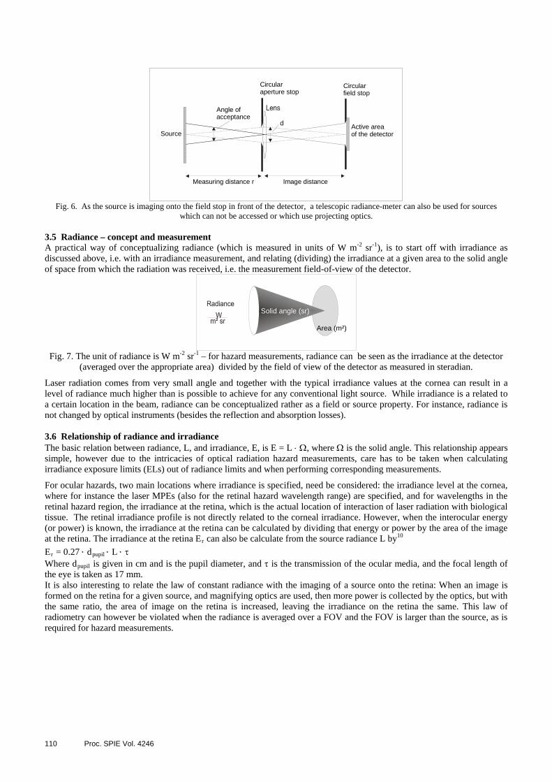
By imaging the source onto the field stop (Fig. 6), the field stop does not have to placed at the source and therefore this set-up can also be used to measure sources which are not accessible or which employ projecting optics. In order to define a FOV, a lens is used to image the source onto the plane of the field stop. The plane angle FOV is determined by the ratio of the diameter of field stop to the distance of the field stop to the lens. In this case, the averaging measurement aperture for the determination of the irradiance part of the radiance measurement is in front of the lens, i.e. the aperture stop of the input optics. Such a set-up is realized in specialized integrating hazard meters as well as in telescopic input optics of radiometers. For both set-ups, the diameter and the distance of the field stop to the aperture stop determines the FOV, while the aperture stop is equivalent to the averaging aperture in the sense of irradiance measurement. For many laser safety measurements and for hazard analysis of optical radiation, the FOV of the detector does not have to fulfil special requirement, as long as all of the source is seen by the detector, i.e. as long as the detector FOV is at least as large as the source size, as the measurement result is not influenced by the size of the FOV as long as the complete source is measured.
110 Proc. SPIE Vol. 4246
Circularfield stop
Source
Circularaperture stop
Image distance
Active areaof the detector
d
Angle ofacceptance
Measuring distance r
Fig. 6. As the source is imaging onto the field stop in front of the detector, a telescopic radiance-meter can also be used for sources
which can not be accessed or which use projecting optics. 3.5 Radiance – concept and measurement A practical way of conceptualizing radiance (which is measured in units of W m-2 sr-1), is to start off with irradiance as discussed above, i.e. with an irradiance measurement, and relating (dividing) the irradiance at a given area to the solid angle of space from which the radiation was received, i.e. the measurement field-of-view of the detector.
Area (m²)
Solid angle (sr)
Fig. 7. The unit of radiance is W m-2 sr-1 – for hazard measurements, radiance can be seen as the irradiance at the detector
(averaged over the appropriate area) divided by the field of view of the detector as measured in steradian. Laser radiation comes from very small angle and together with the typical irradiance values at the cornea can result in a level of radiance much higher than is possible to achieve for any conventional light source. While irradiance is a related to a certain location in the beam, radiance can be conceptualized rather as a field or source property. For instance, radiance is not changed by optical instruments (besides the reflection and absorption losses). 3.6 Relationship of radiance and irradiance The basic relation between radiance, L, and irradiance, E, is E = L ⋅ Ω, where Ω is the solid angle. This relationship appears simple, however due to the intricacies of optical radiation hazard measurements, care has to be taken when calculating irradiance exposure limits (ELs) out of radiance limits and when performing corresponding measurements. For ocular hazards, two main locations where irradiance is specified, need be considered: the irradiance level at the cornea, where for instance the laser MPEs (also for the retinal hazard wavelength range) are specified, and for wavelengths in the retinal hazard region, the irradiance at the retina, which is the actual location of interaction of laser radiation with biological tissue. The retinal irradiance profile is not directly related to the corneal irradiance. However, when the interocular energy (or power) is known, the irradiance at the retina can be calculated by dividing that energy or power by the area of the image at the retina. The irradiance at the retina Er can also be calculate from the source radiance L by10
Er = 0.27 ⋅ dpupil ⋅ L ⋅ τ Where dpupil is given in cm and is the pupil diameter, and τ is the transmission of the ocular media, and the focal length of the eye is taken as 17 mm. It is also interesting to relate the law of constant radiance with the imaging of a source onto the retina: When an image is formed on the retina for a given source, and magnifying optics are used, then more power is collected by the optics, but with the same ratio, the area of image on the retina is increased, leaving the irradiance on the retina the same. This law of radiometry can however be violated when the radiance is averaged over a FOV and the FOV is larger than the source, as is required for hazard measurements.

Proc. SPIE Vol. 4246 111
3.7 Averaging of radiance There is a Golden rule of radiance measurements: the source has to underfill the detector’s FOV. This is a simplified expression of the requirement that the measurement FOV needs to be small enough to resolve the radiance profile of the source (compare irradiance measurement). Just as for irradiance hotspots, radiance measurements performed with a given FOV can not characterize radiance hotspots (which will become irradiance hotspots in the image plane) which are smaller than the measurement FOV. When the source is smaller than the measurement (averaging) FOV, then the resulting value is smaller than the physical radiance of the source, and can be seen as a effective radiance. This effective radiance is directly related to an effective irradiance on the retina.
4. DOSIMETRIC CONCEPTS SPECIFIC TO LASER SAFETY AND OPTICAL RADIATION HAZARD ANALYSIS
4.1 Dosimetry for biomedical studies as basis for exposure limits Animal studies and some limited information regarding human exposure are the basis for the setting of exposure limits of optical radiation. In animal studies, a number of exposures are performed for a given wavelength, exposure duration and irradiated spot diameter, while varying the exposure level. A threshold is subsequently identified for the given wavelength, exposure duration and spot diameter, where no injury was observed for exposures below the threshold level and injury was observed above the threshold level. However, especially for the retina, due to biological variability in the level of threshold from specimen to specimen or for different locations within one retina, a statistical distribution for the threshold is found rather than a sharp threshold11. As representative point of the distribution, the ED50 is usually reported, which is the exposure level which produced an injury in 50 % of the exposures. An exposure limit is set by the responsible committee, which currently is the ICNIRP, following a review of the available experimental data. The exposure limit is set so that it lies below the ED50 as identified by experimental animal studies by introducing a “safety factor”, which is typically in the range of a factor 10, however can be somewhat less if the uncertainty about the threshold is small. The difference can also be larger when the wavelength or pulse duration dependence of the EL has been simplified in comparison to the corresponding trend in the experimental data. For a discussion of the dosimetry regarding experimental studies which are designed to quantify a threshold for injury, and the radiometric relation to the corresponding EL, specific wavelength ranges and consequently the type of tissue at risk need to be distinguished. Generally, the location of the injury corresponds to the location of the (main) absorption of the wavelength. For optical radiation hazards, the tissues at risk are the cornea and the lens of the eye for wavelengths in the ultraviolet and the infrared above 1400 nm, the retina in the wavelength range of 400 nm to 1400 nm, and the skin. For the cornea and lens, experimental ED50 and threshold values are typically reported as irradiance or radiant exposure at the cornea. In practice, for laser beams, the power or energy per pulse of the laser beam is measured and the irradiated spot diameter on the cornea is determined at the 1/e level. The reported irradiance or radiant exposure value is the result of a division of the power or energy per pulse by the area of the irradiated spot using the 1/e definition of beam diameter. For exposure of the skin, the procedure is equivalent. For the retina, experimental ED50 and threshold values are usually reported in terms of the power or energy which is incident on the cornea and enters the pupil, which is referred to either as intraocular energy, IOE, or as total intraocular energy, TIE. The energy or power incident on the retina can be determined by considering reflection and absorption losses in the ocular media in front of the retina. Additionally to the power or energy, the diameter of the irradiated spot on the retina is also necessary to fully characterize the level of exposure. 4.2 Aperture averaging for optical radiation hazard evaluation When an irradiance profile is averaged over a given aperture, then the resulting value represents an effective value which is smaller than the maximum physical value of the irradiance profile. For laser safety and hazard evaluation of broadband optical radiation, it is this effective hazard which is to be compared to the exposure limit. The size of the averaging aperture is determined by biological factors such as the optical properties of the eye, body movements and scattering. For the example of skin exposure lasting for several seconds, the movement of the body will average an irradiance profile on the skin over an area of at least several square millimeters, even if the irradiated body part is kept still. Especially in the near-infrared, radiation is penetrating relatively deep into skin and due to scattering, the irradiance profile is averaged over corresponding dimensions. In the laser safety standards, averaging apertures are specified for different wavelength ranges, separately for the eye and the skin.

112 Proc. SPIE Vol. 4246
Table 9 of IEC 60825-1 – Aperture diameter applicable to measuring laser irradiance and radiant exposure
Spectral region nm
Aperture diameter for Eye mm
Skin mm
180 to 400 1 3.5 ≥ 400 to 1 400 7 3.5
≥ 1 400 to 105 1 for t ≤ 0.35 s 1.5 t3/8 for 0.35 s < t < 10 s 3,5 for t ≥ 10 s.
3.5
≥ 105 to 106 11 11 In 1997, ICNIRP published guidelines for optical broadband radiation2, where maximum permissible exposures are defined alongside with the minimal averaging aperture diameters. An aperture diameter of 25 mm is specified, only for the case of an inhomogeneous field, the averaging aperture size should be reduced to 7 mm. An extreme example is a laser beam which produces an irradiated area on the detector of, for example, 1 mm2. Let us further assume that the optical power contained in this laser beam equals 0.1 mW, and that the laser radiation is in the visible spectral range and the aperture of the detector or the detector surface has a diameter of 7 mm, corresponding to an area 3.6 10-4 m2. A radiometer calibrated in Watts would display a value of 0.1 mW – the irradiance obtained by dividing with the area of the 7 mm aperture would give about 2.6 W m-2. However the actual physical irradiance in the laser beam would be (for the simplifying assumption of a top-hat beam) 0.1 mW divided by 1 mm2, which equals 100 W m-2. It is interesting to note that in this example, the irradiance value obtained by averaging over an aperture of 7 mm diameter is the correct value to be compared to the exposure limit of laser radiation for inadvertent exposure, which is given as irradiance on the cornea of 25 W m-2. The averaging aperture of 7 mm corresponds to the maximum diameter of a dark-adapted pupil and is therefore the biological relevant dimension over which the irradiance is “biologically” averaged. Therefore 2.6 W m-2 is the irradiance value which has to be compared to the applicable exposure limit of 25 W m-2 and not the actual physical irradiance value which is much larger. This example shows the importance of specifying the appropriate averaging aperture size together with the exposure limit. If the averaging aperture is not specified, the actual physical irradiance might be compared to the exposure limit, which, for the case of hot-spots or small beams, would lead to an unnecessarily-restrictive hazard evaluation. It is important to note, that values specified for the averaging aperture diameter are the smallest apertures to be used to obtain an averaged value of irradiance to be compared with the exposure limits - if smaller averaging apertures were used, for the case of hotspots, the hazard would be over-estimated. If the irradiating field is homogenous over a given area which is larger than the minimum aperture size, then the measurement aperture can be larger than the specified minimum value. By way of example, if one did not account for body-movements, a 1 mm diameter aperture would seem appropriate for UV-measurements, however the radiant exposure in the wavelength range of UV radiation will practically never have to be measured with an averaging aperture of 1 mm diameter, as this would be only relevant for hazard evaluation of exposure to pulses produced by ultraviolet lasers. It should be noted that for the measurement of homogeneous irradiation, the usage of a larger aperture is actually advantageous, as the measurement accuracy is improved due to a larger signal. 4.3 Cosine dependence for skin exposure For the measurement of radiation to be compared to limits concerning irradiation of the surface of the body, i.e. the skin and the surface of the eye, the detector should have a plane angle of acceptance of 2π, and a cosine-response regarding the sensitivity of the detector for different angles of incidence, mimicking the irradiation of a flat surface where the irradiance is decreased with the cosine of the incidence angle, as is schematically shown in Fig. 8.
Angle of incidence β
E W/m²
E cos W/m²β
Fig. 8. For measurements of radiation to be compared to exposure limits of the skin, the detector should have a
cosine response in regard to the sensitivity as a function of the incidence angle.

Proc. SPIE Vol. 4246 113
The cosine response of a detector however only comes into play when large sources are measured at close distance. If the angle of incidence of the incident rays does not vary much, then also the dependence of the sensitivity of the radiometer as a function of angle of incidence has no influence on the measurement. 4.4 Eye movements For exposure to flashes of light, the retina appears to be resting in respect to the image on the retina, and the angular subtense α, with a minimal value of αmin, can be used to estimate the size of the irradiated area on the retina and the corresponding irradiance. For continuous exposure situations, however, eye-movements will result in the movement of the image on the retina, causing the irradiated retinal area to be larger than the optical image size α, as is schematically depicted in Fig. 9. The extent of the eye-movements is time dependent: for very short exposures, the retina will be fixed in respect to the image for the duration of the exposure. With increasing exposure duration, eye-movements will increase from involuntary tremors to larger, task oriented eye-movement and for very long exposure durations under realistic situations, even head movements would come into play.
Fig. 9. In this diagram, the image on the retina is represented by a grey disk, and the eye movements are
visualised by the location of the image at given time intervals. Eye movements will result in relative motions of the image over the retina, comparable to a photographic film being moved in relation to the image.
This however distributes the radiant energy over a larger area, thereby decreasing the hazard. Such eye-movements will increase the effectively irradiated and therefore also the potentially damaged area on the retina. However due to these eye-movements and the correspondingly increased irradiated area, the effective irradiance on the retina as defined by the power entering the eye divided by the effectively irradiated area, will decrease correspondingly, thereby decreasing the level of hazard as compared to the irradiation of a fixated eye for the same exposure duration. The general tendency is: longer exposure duration → larger eye movements → larger effectively irradiated area → smaller effective irradiance → decreased hazard Since the retinal photochemical hazard depends on the irradiance on the retina and not on the image size, the concept of accounting for the influence of eye movement by a time dependent averaging FOV is adopted for the specification of the MPEs and measurement requirements for the photochemical retinal MPE, both for laser radiation as well as for broadband radiation. 4.5 FOV averaging for the photochemical hazard evaluation Usually, if the level of the hazard is decreased, this is expressed by increasing the exposure limit, allowing for a higher exposure level. For the case of a decrease of the hazard due to eye-movements, this relaxation is not expressed as increase of the exposure limit as given in radiance, but by an increase of the averaging FOV. As discussed above, if the FOV is larger than the source, then the measured radiance value will be smaller than the actual physical radiance of the source. An increase of the averaging FOV results in a decrease of the effective radiance measurement value, as this value is derived by division with the averaging measurement FOV. Thereby the decrease of the hazard is not reflected by an increase of the exposure limit, but by a decrease of the measured effective value which is to be compared to the exposure limit. The specification of an averaging FOV results in the measurement of a biologically effective radiance value, which might be smaller than the physical radiance value of the source. Therefore, the effective radiance value should be seen as a parameter related to the exposure of the retina rather than as a property of the source. The law of conservation of radiance and the independence of the radiance in regard to the distance to the source also only applies to the physical real radiance, not to effective averaged radiance, as the effective retinal irradiance will remain

114 Proc. SPIE Vol. 4246
unchanged as long as the (magnified) image is smaller than the extent of the eye movements (the effective irradiance on the retina is derived by dividing the intraocular power by the area reflecting the retinal area covered by the eye movements. In several documents, the Greek letter γ is used to denominate the averaging plane angle FOV to prevent confusion with the source size α and with the minimal retinal spot size αmin. In the ICNIRP guidelines for broadband radiation2, the averaging FOV is specified to be 11 mrad for exposure durations between 10 s and 100 s. It is difficult to quantify the minimal averaging effect of eye-movements for exposure durations greater than 100 seconds and up to 10.000 s, which is about 2 ½ hours. According to the ICNIRP guidelines for broadband radiation, for exposure durations greater than 100 s, the averaging FOV is increased linearly up to 0.2 radian at 10,000 seconds. In the course of the current revision of the laser exposure limits, ICNIRP will specify3 a square-root dependence of the plane angle averaging FOV, γ, which translates into a simple linear dependence of the solid angle averaging FOV, Γ, on the exposure duration. It is suggested here to adopt this specification, as reproduced below, also for broadband radiation. Short time exposure γ = 1.7 mrad Γ = 2.3 10-6 sr (relevant for thermal retinal broadband hazard only) 10 s – 100 s γ = 11 mrad Γ = 10-4 sr 100 s – 10 000 s mradt1.1=γ Γ = 10-6 ⋅ t sr t > 10 000 s γ = 110 mrad Γ = 10-2 sr It should be noted, that the value of 1.7 mrad is specified by ICNIRP to be the averaging FOV for the retinal thermal hazard for the wavelength range of 380 nm to 1,400 nm, which is relevant for short time exposures. For the blue light photochemical retinal hazard, relevant exposure durations are 10 seconds and longer, and the above values for the averaging FOVs for times greater than 10 seconds apply. For the evaluation of near infrared sources that provide no strong visual stimulus, the exposure limit for thermal damage of the retina is defined for exposure durations larger than 10 seconds, and the radiance measurement has to be averaged over γ = 11 mrad. The consequences of the averaging FOV for practical hazard measurements shall be discussed for two FOV sizes in relation to a small and a large source, as schematically shown in Fig. 9.
Fig. 10. Possible relations of source size to the averaging FOV as specified for two different exposure durations. If the source is smaller
than the FOV, the measured averaged value is smaller than the physical value, if the source is larger than the FOV, the source will be sampled for hot-spots with the specified FOV.
For the example of a source size of α = 11 mrad, the averaging FOV for an exposure duration between 10 s and 100 s is γ = 11 mrad. For a homogeneous source, the measured effective radiance value will be the same as the physical radiance. If the same source is evaluated for longer exposure durations, the averaging FOV increases corresponding to increased eye-movements, thereby the biologically effective radiance value as averaged over γ is smaller than the real physical radiance of the source. On the other hand, for the case of a source of for instance α = 110 mrad, the specification of an averaging FOV of γ = 11 mrad means that the source is to be sampled for hot-spots. The examples also show, that for a given exposure duration the specified averaging FOV γ corresponds to a minimal image size, above which the effective averaged radiance is equal to the physical radiance, i.e. there does not seem to be a reduction in the hazard due to eye-movements for sources larger than γ. This can be understood on the basis of Fig. 10, where the image of a small and large source is represented by grey disks and for both sources the distribution corresponds to the same geometrical extent of eye-movements for a given time (i.e. the centres of the disks are at the same positions in both cases).

Proc. SPIE Vol. 4246 115
Fig. 11: Comparison of the effectively irradiated retinal area for the same extent
of eye-movements for small and large source sizes: for large sources, i.e. images, the extent of the eye-movements is not large to significantly increase the effectively irradiated area.
If the extent of the eye-movements is small compared to the image size, then the irradiated area on the retina will correspond to the image size α. Therefore, for larger image sizes only larger eye-movements can significantly increase the effectively irradiated area on the retina. 4. 6 Photochemical retinal broadband limit “Blue light hazard” The broadband radiation exposure limit for the photochemical retinal hazard, which is also often referred to as „Blue Light Hazard“, is given by ICNIRP as2:
srmJtLB 2
610≤⋅
where LB is the effective blue-light radiance at the eye and t is the exposure duration. For t > 10,000 s:
srmWLB 2100≤
The term „effective“ indicates that the spectral radiance Lλ of the broadband source is weighted with the blue light hazard action spectrum B(λ) and is subsequently integrated over the wavelength λ: ∑ ∆⋅⋅=⋅
700
300)( λλλ tBLtLB
4.7 Relation of radiance MPE to irradiance MPE The basic relation between radiance, L, and irradiance, E, is E = L ⋅ Ω where Ω is the solid angle. This relationship appears simple, however due to the intricacies of optical radiation hazard measurements, care has to be taken when calculating irradiance exposure limits (ELs) out of radiance limits and when performing corresponding measurements. The most straightforward case is a source with angular subtense α, which is smaller than the averaging FOV, γ. In this case, the measured effective radiance value does not depend on the angular subtense of the source, and it also does not depend on the actual value of the measurement FOV, as long as the FOV is larger than the source, and as long as the radiance value is obtained by dividing the irradiance value by the specified averaging FOV, Γ. Consequently the radiance-EL can be multiplied with the averaging FOV to obtain the exposure limit given as irradiance at the cornea, and the measurement can be performed with a regular irradiance detector with an “open”, i.e. large, FOV. Specifically, this is done for the photochemical retinal limit, where the basic exposure limit is 106 W m-2 sr-1. The exposure limit expressed as irradiance is obtained by multiplying with the appropriate averaging FOV Γ (see above), i.e. with Γ = 10-4 sr (γ = 11 mrad) for exposure durations from 10 to 100 s:
106 J m-2 sr-1 ⋅ 10-4 sr = 100 J m-2 This value is specified by ICNIRP2 and ACGIH12 to be valid for sources with angular subtense smaller than 11 mrad (“small” sources). By multiplying the radiance-EL with the averaging FOV, the relaxation of the hazard due to eye-movements is contained in the exposure limit, which is not the case for the radiance-ELs, where the averaging is contained in the measurement value, which is to be compared with the radiance-EL. This relationship between the ELs and averaging FOV can be seen when the blue light irradiance-EL is derived for very long exposure durations*****, where γ = 110 mrad, i.e. Γ = 10-2 sr:
106 J m-2 sr-1 ⋅ 10-2 sr = 104 J m-2 A comparison with the value for exposure durations of 10 to 100 s shows, that the EL is larger for very long exposure durations. The relaxation of the hazard due to larger eye-movements results in an increase of the EL, if the EL is expressed as irradiance. For both evaluations, i.e. for 10 – 100 s and for very long exposure durations, the irradiance measurement
***** An equivalent derivation of the blue light exposure limit for a 10,000 s exposure duration is the background for the limit of 0.8 W m-2, as specified in the IESNA lamp safety standards6 for the exempt group. There a value of γ = 100 mrad has been used.

116 Proc. SPIE Vol. 4246
value is the same, in contrast to the specification of the EL as a radiance value, where the value of the EL does not depend on the exposure duration, but the relaxation of the hazard is mirrored by a decrease of the effectively measured radiance value. It should be noted that the irradiance blue light limit is fully equivalent to the radiance-EL, provided that the radiance measurement is performed with the specified averaging FOV, and it is not a relaxation, as indicated in by ACGIH12. The exposure limit for the blue-light hazard for exposure durations greater than 100 seconds up to 30,000 seconds can be given in a simple form when the irradiance MPE is derived from the radiance limit with the averaging field of view as specified as function of time and is subsequently divided by the exposure duration to obtain a value for irradiance:
MPEirradiance = 1 W m-2 It is mentioned above, that the irradiance limits are valid for sources smaller than the averaging angle, which implies that an “open”-FOV irradiance radiometer, as is common for laser measurements, is used for the hazard measurements. If the source were larger than γ, then one would measure a larger level of radiation, and the hazard would be overestimated as compared to the radiance-case, where the FOV is limited to γ. If the FOV for the irradiance measurement were also limited to γ, for instance by placing an aperture at the source, there would be a full equivalence to radiance measurements and the irradiance-ELs could also be applied to sources larger than γ. In this case however, γ is not an averaging FOV, but rather a limiting FOV, as it prevents that radiation from outside the FOV contributes to the measured irradiance. For the case that the source is homogeneous and an “open” field of view (i.e. larger than the source size α) is to be used, the exposure limits could be corrected for the larger measured value by increasing the exposure limit correspondingly: MPEirradiance open = MPEirradiance ⋅ α2 γ-2 If the source is not homogenous, this method would underestimate the hazard, as it would correspond to averaging over the source size, whereas the usage of the specified averaging field of view would be used to scan the source for hotspots, i.e. for maximised measurement values, which would have to be compared to the exposure limit.
ACKNOWLEDGEMENTS The author would like to express his appreciation for many spirited and informative discussions with David Sliney US Army Center for Health Promotion and Preventive Medicine, MD, and John Mellerio, School of Biosciences, University of Westminster, London.
REFERENCES 1. ICNIRP “Guidelines on Limits of Exposure to Laser Radiation of Wavelengths between 180 nm and 1,000 µm”, Health
Physics 71, p. 804-819, 1996. 2. ICNIRP “Guidelines on Limits of Exposure to Broad-band Incoherent Optical Radiation (0,38 to 3 µm)”, Health
Physics 73, p. 539-554, 1997. 3. ICNIRP, “Revision of Guidelines on Limits of Exposure to Laser Radiation of Wavelengths between 180 nm and
1,000 µm”, Health Physics 79 p. 431-440, 2000. 4. IEC 60825-1 “Safety of laser products Part 1: Equipment classification, requirements and user’s guide”, 1997,
Amendment A2 2001. 5. ANSI Z136.1 “American National Standard for Safe Use of Lasers”, 2000. 6. ANSI/IESNA RP-27.3-96 “Recommended Practice for Photobiological Safety for Lamps – Risk Group Classification
& Labeling”, 1996. 7. CIE “Photobiological Safety of Lamps and Lamp Systems”, to be published 2001. 8. TR IEC 60825-8 “Safety of laser products Part 9, Compilation of maximum permissible exposure to incoherent optical
radiation (broadband sources)”, 1999. 9. McCluney, R., Introduction to Radiometry and Photometry, p. 116 f, Artech House, MA, 1994 10. D. H. Sliney and M. Wolbarsht, Safety with Lasers and Other Optical Sources, New York, Plenum Publishing Corp., 1980. 11. K. Schulmeister, G. Sonneck, H. Hödlmoser, F. Rattay, J. Mellerio and D. Sliney, Modeling of uncertainty associated
with dose–response curves as applied for probabilistic risk assessment in laser safety, SPIE Vol. 4246, San Jose, 2001, Laser and Noncoherent Light Ocular Effects: Epidemiology, Prevention, and Treatment, Ed. B. E. Stuck and M. B. Belkin (these proceedings), 2001.
12. ACGIH, American Conference of Industrial Governmental Hygienists, TLVs and BEIs for Chemical Substances and Physical Agents, Photochemical injury from blue light, p. 107 f, 1996.