Embed Size (px)
Citation preview
CONCEPTS FOR A SAFETY DEVICE IN CONVENTIONALTRACK-LINKAGE KINEMATICS TO PREVENT SKEW IN A SINGLE
FLAP SYSTEM
M. Lerch, F. ThieleckeHamburg University of Technology, Institute of Aircraft Systems Engineering
Nesspriel 5, 21129 Hamburg, Germany
Abstract
Conventional high-lift systems are used for lift augmentation during start and landing operations of the majorityof modern transport aircraft. Besides this, they have limited functionality during the rest of a flight mission. Apossibility to provide more functionality is the use of single flap systems, that enables differential flap setting.For the implementation different technical realization can be used. In addition to dropped-hinge kinematic andfail-safe actuators, this paper presents various concepts for a novel safety device, which is integrated into thetrack linkage kinematic. For the so called flap track brake (FTB) an integration into the carriage is conceivable.The main task of the FTB is the prevention of flap skew in failure cases. Therefore different concepts arepresented and discussed. For carriage integrated concepts a VDI 2225 like evaluation is conducted. The use ofthe FTB requires an adjusted drive system, which actuates every single flap with an independent and redundantelectrical power unit. For investigations of the FTB and drive system in early development stage a co-simulationcan be used to gain early results. Therefore the drive system can be modeled in MATLAB/Simulink and the flapkinematics are emulated in MSC/Adams.
1 INTRODUCTION
Today’s civil transport aircraft provide lift augmentationsystems for low airspeed operations. This is achivedby extending high-lift systems installed at the leading(slats) and trailing edge (flaps) of the wing. Researchactivities of the INSTITUTE OF AIRCRAFT SYSTEMSENGINEERING from the HAMBURG UNIVERSITY OFTECHNOLOGY (TUHH) enter the question how to pro-vide more functionality to flap high-lift systems. TheAirbus A350 was a first industrial step in this direc-tion, where differential flap setting was enabled [1].Proceeding single-flap systems, where every flap isan independent sub-system, consequently have nomechanical coupling due to the transmission and otherconnecting elements between the flaps. New systemarchitectures and devices will be needed to preventflap skew and provide a safe and reliable airplaneoperation. This paper will present possible conceptsand system architectures to achieve this goals.Therefore the first part of the paper gives an overviewabout conventional trailing edge high-lift systems toclarify the difference to single flap systems. Moreoverpossible failure cases and their state of the art detec-tion are described.The next part points out the advantage and gainin functionality of high-lift systems with enhanced
functionality. Therefore three options for a possibletechnical realization of a single-flap system are pre-sented. One option, next to dropped hinge kinematicsand fail-safe actuators, is a novel safety device, in-tegrated into track linkage kinematics components,called flap-track brake (FTB).General boundary conditions for this FTB and thepossible actuation system will be introduced in thesubsequent section. Furthermore potential failurecases are outlined, a kinematic analysis and the useof multi-body simulations for preliminary investigationsare described.Concepts for carriage integrated FTBs are presentedin the following section. These concepts are evaluatedaccording to VDI 2225.
2 CONVENTIONAL HIGH LIFT SYSTEM
To clarify the difference between a conventional anda single flap system, this section provides a briefoverview of the state of the art trailing edge high-liftsystems.Today the majority of airplanes have two pairs of flaps,named after their position, the inboard and outboardflaps. Flaps of airplanes like the Airbus A320 or Boeing737 realize a so called fowler motion. This motion pro-
©2017
Deutscher Luft- und Raumfahrtkongress 2017DocumentID: 450068
1
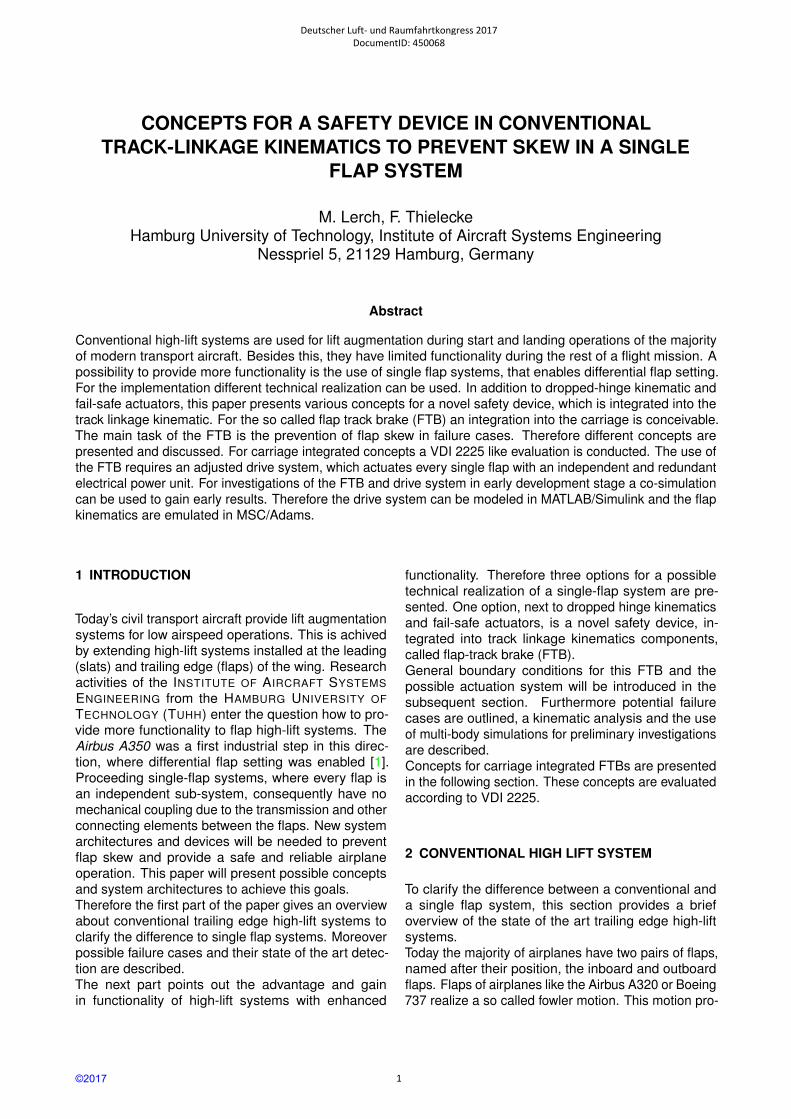
vokes an extension of the wing area and increases thewing camber, which can increase the lift for a single-slotted system up to 93% [2] in comparison to a cruiseconfiguration. The beginning of the flap extensionis characterized by a nearly translational movementwhich changes into a rotational movement at the endof flap extension.
Geared rotary actuatorCarriage
Drive strut
Flap
Track
Trackbeam
Wing
FIG. 1: Schematic representation of track kinematics
A large variation of kinematic mechanisms, which en-sure these motion characteristics can be found in thedifferent airplane types. One widely used kinematic isthe track linkage kinematic (see figure 1 for schematicrepresentation), that can be found in most Airbus(A330/340, A320) and Boeing (737, 777) airplanes.Except the most inner station a flap is mounted on twoor three of those guiding mechanisms. The carriagecan move translational along the trackbeam and with-stands the main load. The trackbeam itself is mountedto the wing structure.
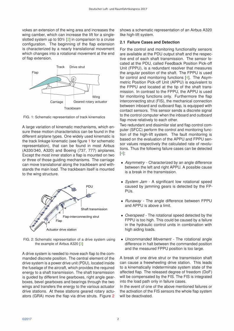
FIG. 2: Schematic representation of a drive system usingthe example of Airbus A320 [3]
A drive system is needed to move each flap to the com-manded discrete position. The central element of thedrive system is a power drive unit (PDU), located insidethe fuselage of the aircraft, which provides the requiredenergy to a shaft transmission. The shaft transmissionis guided by different line gearboxes, right angle gear-boxes, bevel gearboxes and bearings through the twowings and transfers the energy to the various actuatordrive stations. At these stations geared rotary actu-ators (GRA) move the flap via drive struts. Figure 2
shows a schematic representation of an Airbus A320like high-lift system.
2.1 Failure Cases and Detection
For the control and monitoring functionality sensorsare available at the PDU output shaft and the respec-tive end of each shaft transmission. The sensor lo-cated at the PDU, called Feedback Position Pick-offUnit (FPPU), is a redundant resolver that measuresthe angular position of the shaft. The FPPU is usedfor control and monitoring functions [4]. The Asym-metric Position Pick-off Unit (APPU) is equivalent tothe FPPU and located at the tip of the shaft trans-mission. In contrast to the FPPU, the APPU is usedfor monitoring functions only. Furthermore the flapinterconnecting strut (FIS), the mechanical connectionbetween inboard and outboard flap, is equipped withcontact sensors. This sensor sends a discrete signalto the control computer when the inboard and outboardflap move relatively to each other.Two redundant and dissimilar slat and flap control com-puter (SFCC) perform the control and monitoring func-tion of the high-lift system. The fault monitoring isbased on the evaluation of the APPU and FPPU sen-sor values respectively the calculated rate of revolu-tions. Thus the following failure cases can be detected[4]:
• Asymmetry - Characterized by an angle differencebetween the left and right APPU. A possible causeis a break in the transmission.
• System Jam - A significant low rotational speedcaused by jamming gears is detected by the FP-PUs.
• Runaway - The angle difference between FPPUand APPU is above a limit.
• Overspeed - The rotational speed detected by theFPPU is too high. This could be caused by a failurein the hydraulic control units in combination withhigh aiding loads.
• Uncommanded Movement - The rotational angledifference in halt between the commanded positionand the measured FPPU position is too large.
A break of one drive strut or the transmission shaftcan cause a freewheeling drive station. This leadsto a kinematically indeterminate system state of theaffected flap. The released degree of freedom (DoF)will be compensated by the FIS. The FIS is integratedinto the load path only in failure cases.In the event of one of the above mentioned failures orthe activation of the FIS sensors the whole flap systemwill be deactivated.
©2017
Deutscher Luft- und Raumfahrtkongress 2017
2
3 HIGH-LIFT SYSTEMS WITH ENHANCED FUNC-TIONALITY
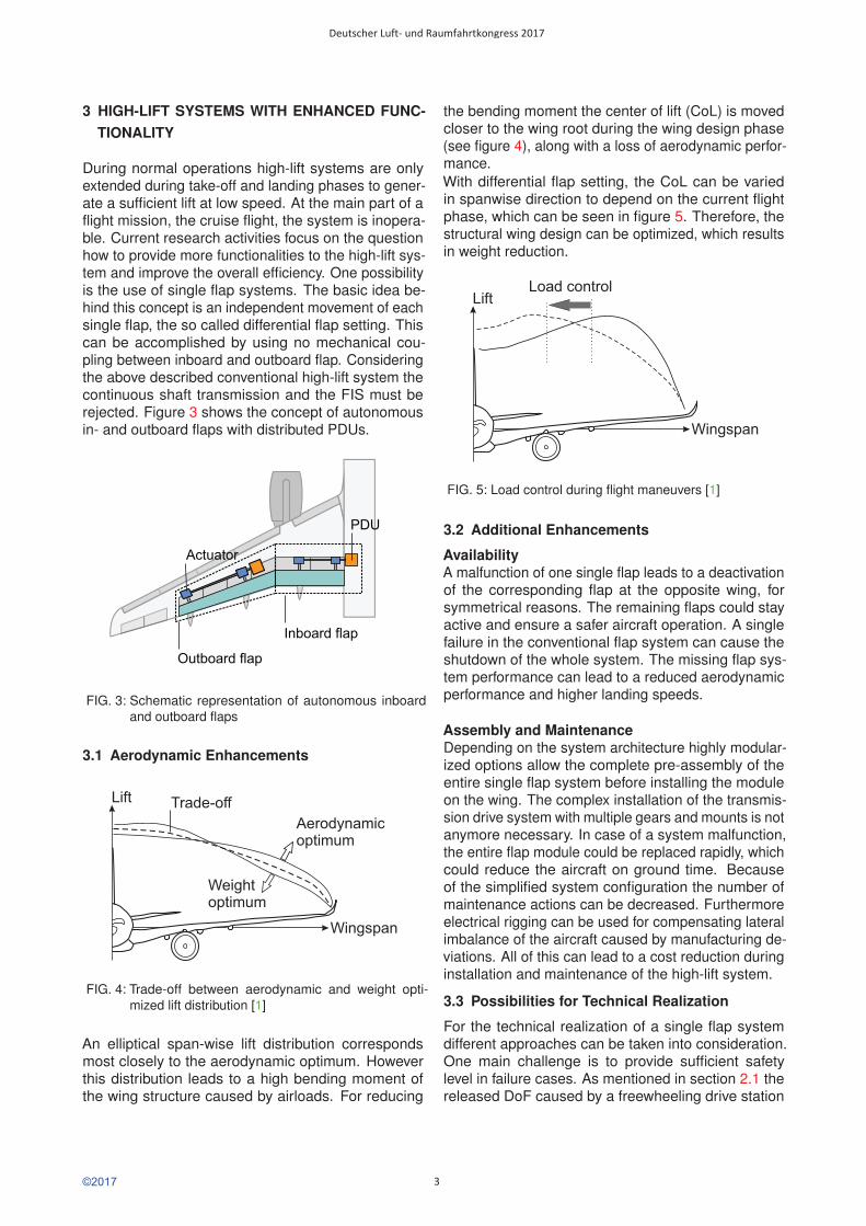
During normal operations high-lift systems are onlyextended during take-off and landing phases to gener-ate a sufficient lift at low speed. At the main part of aflight mission, the cruise flight, the system is inopera-ble. Current research activities focus on the questionhow to provide more functionalities to the high-lift sys-tem and improve the overall efficiency. One possibilityis the use of single flap systems. The basic idea be-hind this concept is an independent movement of eachsingle flap, the so called differential flap setting. Thiscan be accomplished by using no mechanical cou-pling between inboard and outboard flap. Consideringthe above described conventional high-lift system thecontinuous shaft transmission and the FIS must berejected. Figure 3 shows the concept of autonomousin- and outboard flaps with distributed PDUs.
FIG. 3: Schematic representation of autonomous inboardand outboard flaps
3.1 Aerodynamic Enhancements
Lift
Wingspan
Weightoptimum
Aerodynamicoptimum
Trade-off
FIG. 4: Trade-off between aerodynamic and weight opti-mized lift distribution [1]
An elliptical span-wise lift distribution correspondsmost closely to the aerodynamic optimum. Howeverthis distribution leads to a high bending moment ofthe wing structure caused by airloads. For reducing
the bending moment the center of lift (CoL) is movedcloser to the wing root during the wing design phase(see figure 4), along with a loss of aerodynamic perfor-mance.With differential flap setting, the CoL can be variedin spanwise direction to depend on the current flightphase, which can be seen in figure 5. Therefore, thestructural wing design can be optimized, which resultsin weight reduction.
Load controlLift
Wingspan
FIG. 5: Load control during flight maneuvers [1]
3.2 Additional Enhancements
AvailabilityA malfunction of one single flap leads to a deactivationof the corresponding flap at the opposite wing, forsymmetrical reasons. The remaining flaps could stayactive and ensure a safer aircraft operation. A singlefailure in the conventional flap system can cause theshutdown of the whole system. The missing flap sys-tem performance can lead to a reduced aerodynamicperformance and higher landing speeds.
Assembly and MaintenanceDepending on the system architecture highly modular-ized options allow the complete pre-assembly of theentire single flap system before installing the moduleon the wing. The complex installation of the transmis-sion drive system with multiple gears and mounts is notanymore necessary. In case of a system malfunction,the entire flap module could be replaced rapidly, whichcould reduce the aircraft on ground time. Becauseof the simplified system configuration the number ofmaintenance actions can be decreased. Furthermoreelectrical rigging can be used for compensating lateralimbalance of the aircraft caused by manufacturing de-viations. All of this can lead to a cost reduction duringinstallation and maintenance of the high-lift system.
3.3 Possibilities for Technical Realization
For the technical realization of a single flap systemdifferent approaches can be taken into consideration.One main challenge is to provide sufficient safetylevel in failure cases. As mentioned in section 2.1 thereleased DoF caused by a freewheeling drive station
©2017
Deutscher Luft- und Raumfahrtkongress 2017
3
shall not result in a critical situation. In the following,three different approaches for the technical realizationof single flap systems are described.
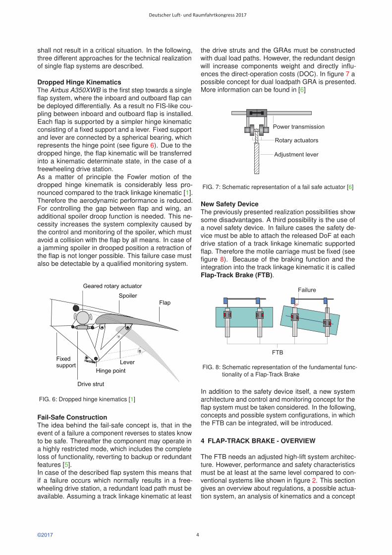
Dropped Hinge KinematicsThe Airbus A350XWB is the first step towards a singleflap system, where the inboard and outboard flap canbe deployed differentially. As a result no FIS-like cou-pling between inboard and outboard flap is installed.Each flap is supported by a simpler hinge kinematicconsisting of a fixed support and a lever. Fixed supportand lever are connected by a spherical bearing, whichrepresents the hinge point (see figure 6). Due to thedropped hinge, the flap kinematic will be transferredinto a kinematic determinate state, in the case of afreewheeling drive station.As a matter of principle the Fowler motion of thedropped hinge kinematik is considerably less pro-nounced compared to the track linkage kinematic [1].Therefore the aerodynamic performance is reduced.For controlling the gap between flap and wing, anadditional spoiler droop function is needed. This ne-cessity increases the system complexity caused bythe control and monitoring of the spoiler, which mustavoid a collision with the flap by all means. In case ofa jamming spoiler in drooped position a retraction ofthe flap is not longer possible. This failure case mustalso be detectable by a qualified monitoring system.
FIG. 6: Dropped hinge kinematics [1]
Fail-Safe ConstructionThe idea behind the fail-safe concept is, that in theevent of a failure a component reverses to states knowto be safe. Thereafter the component may operate ina highly restricted mode, which includes the completeloss of functionality, reverting to backup or redundantfeatures [5].In case of the described flap system this means thatif a failure occurs which normally results in a free-wheeling drive station, a redundant load path must beavailable. Assuming a track linkage kinematic at least
the drive struts and the GRAs must be constructedwith dual load paths. However, the redundant designwill increase components weight and directly influ-ences the direct-operation costs (DOC). In figure 7 apossible concept for dual loadpath GRA is presented.More information can be found in [6]
Rotary actuators
Power transmission
Adjustment lever
FIG. 7: Schematic representation of a fail safe actuator [6]
New Safety DeviceThe previously presented realization possibilities showsome disadvantages. A third possibility is the use ofa novel safety device. In failure cases the safety de-vice must be able to attach the released DoF at eachdrive station of a track linkage kinematic supportedflap. Therefore the motile carriage must be fixed (seefigure 8). Because of the braking function and theintegration into the track linkage kinematic it is calledFlap-Track Brake (FTB).
FTB
Failure
FIG. 8: Schematic representation of the fundamental func-tionality of a Flap-Track Brake
In addition to the safety device itself, a new systemarchitecture and control and monitoring concept for theflap system must be taken considered. In the following,concepts and possible system configurations, in whichthe FTB can be integrated, will be introduced.
4 FLAP-TRACK BRAKE - OVERVIEW
The FTB needs an adjusted high-lift system architec-ture. However, performance and safety characteristicsmust be at least at the same level compared to con-ventional systems like shown in figure 2. This sectiongives an overview about regulations, a possible actua-tion system, an analysis of kinematics and a concept
©2017
Deutscher Luft- und Raumfahrtkongress 2017
4
of multi-body simulation use during the design phase.
4.1 Regulations
A new safety device must fulfill the mandatory regula-tions of the aviation authorities for high-lift systems. Inthe following, a brief insight of the principal regulationsis given. The regulations of FAR-/CS-25 [7] are sub-divided into individual sections, which are addressedto the different components (e.g. engine, structure,equipment). Additionally they pay attention to imple-mentation guidelines, which are important for design-ing high-lift systems.The loss of a high-lift system causes, due to the diver-sity of aircraft types, different effects. Thus the regula-tions do not state a specific value for maximum failurerates. Some typical values (given in probability perflight hour (FH)) for a medium-haul aircraft, accordingto [4], are shown below:
• Slats and/or flaps operating at reduced rate: ≤ 10−3
• Slats or flaps cannot longer be moved: ≤ 10−5
• Slats and flaps cannot longer be moved: ≤ 10−6
• Slats or flaps cannot longer be moved without warn-ing or configuration indication: ≤ 10−9
• Runaway of flaps (driven by motor): ≤ 10−9
• Runaway of flaps (driven by airloads): ≤ 10−9
• Asymmetric flap movement: ≤ 10−9
§25.701 demands a synchronization of the left andright winged flaps:
”Unless the airplane has safe flight charac-teristics with the flaps or slats retracted on oneside and extended on the other, the motion offlaps or slats on opposite sides of the planeof symmetry must be synchronized by a me-chanical interconnection or approved equiv-alent means”
Control and safety systems of new single flap systemswithout mechanical coupling between flaps must provethe ability to replace the FIS and power transmissionby robust and reliable monitoring functions. Besidesthe detection of failures, it is necessary to implementsystems like the FTB, that are able to respond to fail-ures, transfer the system into a safe state and give anindication to the pilot.
4.2 Possible Actuation System Architecture
The concept with a flap-track brake is targeted at singleflap systems. Therefore a different drive system, com-pared to the conventional system (see 2) is needed.In the following a presumed target drive system will beintroduced. The assumed actuation architecture refersto the actuation concept presented in [8].
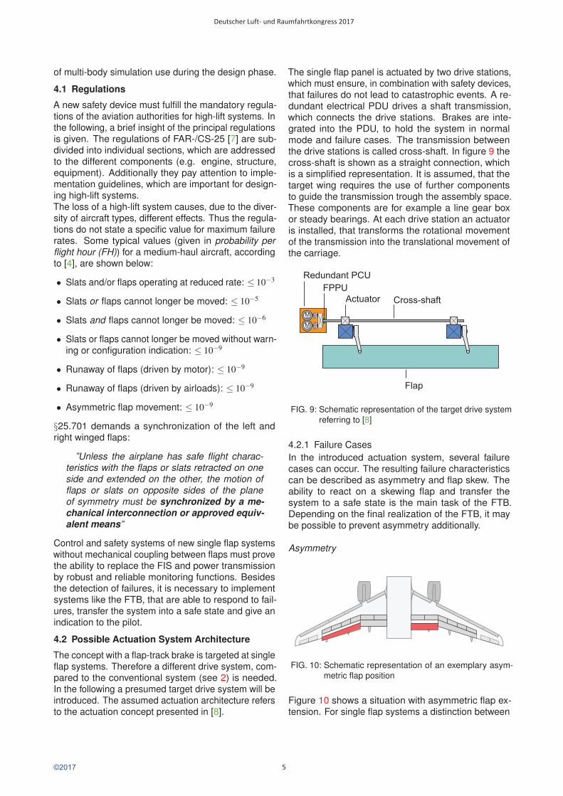
The single flap panel is actuated by two drive stations,which must ensure, in combination with safety devices,that failures do not lead to catastrophic events. A re-dundant electrical PDU drives a shaft transmission,which connects the drive stations. Brakes are inte-grated into the PDU, to hold the system in normalmode and failure cases. The transmission betweenthe drive stations is called cross-shaft. In figure 9 thecross-shaft is shown as a straight connection, whichis a simplified representation. It is assumed, that thetarget wing requires the use of further componentsto guide the transmission trough the assembly space.These components are for example a line gear boxor steady bearings. At each drive station an actuatoris installed, that transforms the rotational movementof the transmission into the translational movement ofthe carriage.
Flap
Redundant PCU
M
FPPU
M
Cross-shaftActuator
FIG. 9: Schematic representation of the target drive systemreferring to [8]
4.2.1 Failure CasesIn the introduced actuation system, several failurecases can occur. The resulting failure characteristicscan be described as asymmetry and flap skew. Theability to react on a skewing flap and transfer thesystem to a safe state is the main task of the FTB.Depending on the final realization of the FTB, it maybe possible to prevent asymmetry additionally.
Asymmetry
FIG. 10: Schematic representation of an exemplary asym-metric flap position
Figure 10 shows a situation with asymmetric flap ex-tension. For single flap systems a distinction between
©2017
Deutscher Luft- und Raumfahrtkongress 2017
5
intended an unintended asymmetry must be made. Anintended asymmetry is part of the extended functional-ity of the single flap systems. A roll moment provokedby aircraft unbalances can be compensated by a com-manded asymmetry.A unintended asymmetry can cause a roll moment,which can not be compensated by other control sur-faces, which leads to a potentially catastrophic situ-ation. Possible causes for a unintended asymmetryare:
• Powered runaway: A failure in the PDU control com-mands, a flap extension at too high or low speed, inthe wrong direction or at the incorrect time.
• Unpowered runaway: The system can move freelycaused by a loss of the mechanical coupling be-tween PDU and drive transmission. Along with theaerodynamic loads the flap can be displaced.
Flap SkewA flap skew can occur by loosing the torque transmis-sion between shaft transmission and flap. Figure 11shows the scenario of a skewing flap.
FIG. 11: Schematic representation of flap skew
Possible causes of this failure are:
• A drive strut break and
• Actuator failure, which leads to a freewheeling drivestation.
A failure combined with maximum airloads can dam-age the whole structural integrity of the flap system. Inthe worst case a flap panel can be lost and may endin a catastrophic event. To avoid these consequencesa FTB with suitable kinematics is needed, which aredescribed in the following section.
4.3 Kinematics of Exemplary Single Flap Systems
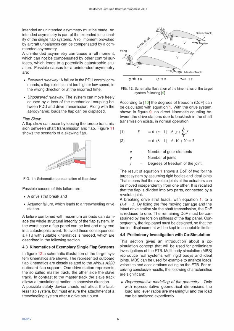
In figure 12 a schematic illustration of the target sys-tem kinematics are shown. The represented outboardflap kinematics are closely related to the Airbus A320outboard flap support. One drive station representsthe so called master track, the other side the slavetrack. In contrast to the master track the slave trackallows a translational motion in spanwise direction.A possible safety device should not affect the fault-less flap system, but must ensure the attachment of afreewheeling system after a drive strut burst.
Wing I
II
IIIIV
V
VI
VIIIVII
Slave-Track
Master-Track
Cross
Shaft
3 R 1 T1 R
FIG. 12: Schematic illustration of the kinematics of the targetsystem following [9]
According to [10] the degrees of freedom (DoF) canbe calculated with equation 1. With the drive system,shown in figure 9, no direct kinematic coupling be-tween the drive stations due to backlash in the shafttransmission exists, in normal operation.
F = 6 · (n−1)−6 ·g+g
∑1
f(1)
= 6 · (8−1)−6 ·10+20 = 2(2)
n − Number of gear elementsg − Number of jointsf − Degrees of freedom of the joint
The result of equation 1 shows a DoF of two for thetarget system by assuming rigid bodies and ideal joints.That means that the revolute joints at the actuators canbe moved independently from one other. It is recalledthat the flap is divided into two parts, connected by arevolute joint.A breaking drive strut leads, with equation 1, to aDoF = 3. By fixing the free moving carriage and theintact drive station via the shaft transmission, the DoFis reduced to one. The remaining DoF must be con-strained by the torsion stiffness of the flap panel. Con-sequently, the flap panel must be designed, so that thetorsion displacement will be kept in acceptable limits.
4.4 Preliminary Investigation with Co-Simulation
This section gives an introduction about a co-simulation concept that will be used for preliminaryinvestigations of the FTB. Multi-body simulation (MBS)reproduce real systems with rigid bodys and idealjoints. MBS can be used for example to analyze loads,velocities and accelerations acting on the FTB. For re-ceiving conclusive results, the following characteristicsare significant:
• Representative modelling of the geometry - Onlywith representative geometrical dimensions theload and lever ratios are meaningful and the loadcan be analyzed expediently.
©2017
Deutscher Luft- und Raumfahrtkongress 2017
6

• Representative modelling of the kinematic behav-ior - The correct implementation of DoF and jointsensures a correct movement behavior compared tothe real system.
• Use of representative airloads - The different posi-tions of the flap deployment cause different airloads.The acting airloads are divided into normal and tan-gential components. Figure 13 shows the changingairloads depending on the flap angle. The extensionof the spoiler has also an influence on the appliedairload. Figure 14 shows the load distribution alongspanwise flap direction for different flap angles. In-cluding the dependency of flap angle and spanwiseload distribution gives a more precise representa-tion of the real load situation and the failure casesget special characteristics depending on the flapextension angle.
• Representative characteristics of the flap panel -To analyze the impact of the flap panel flexibilityeffects on failure characteristic, the panel must rep-resent the panel properties. A main task of thepanel in failure cases, as described in section 4.3,is to constrain a DoF due to the torsion stiffness.Modelling a panel with false torsion stiffness wouldaffect the simulation results negatively.
0 5 10 15 20 25 30 35 40
Flap Angle [°]
-1
-0.5
0
0.5
1
Norm
aliz
ed F
orc
e
Normal Load (0° Spoiler)
Normal Load (35° Spoiler)
Chordwise Load (0° Spoiler)
Chordwise Load (35° Spoiler)
Normal load
Chordwise load
FIG. 13: Total airloads depending on the flap angle andspoiler deployment
As a MSB modeling environment the tool MSC.ADAMScan be used. To get more detailed investigation results,the model of the drive transmission created in MAT-LAB/SIMULINK and the MBS model can be coupledvia co-simulation. Figure 15 presents the principle ofthe concept. This way it is possible to investigate theinfluence of the actuation system on the FTB. In [9] adetailed presentation of the co-simulation possibilitiesis given.
FIG. 14: Spanwise loads distribution of the outboard flap
(M /S )ATLAB IMULINK
M4
M3
Power transmission
System monitoring Flap
u vg h
(S /IMULINK
S )TATEFLOW
(MSC.A )DAMS
FIG. 15: Principle of co-simulation of ADAMS andSIMULINK/STATEFLOW after [9]
A step further is the additional integration of a moni-toring system modeled in MATLAB/STATEFLOW. Thisallows to investigate the influence and accuracy of thedifferent monitoring functions.With an enhanced knowledge of the final FTB designthe MBS co-simulation can be sharpened and resultswith more validity are available.
5 CONCEPTS FOR A FLAP-TRACK BRAKE
For the realization of the FTB some general constraintshave to be established. In the following, principle re-quirements will be presented.
• The reliability and mean time between failure
©2017
Deutscher Luft- und Raumfahrtkongress 2017
7
(MTBF) must be at least equal to comparable AirbusA320 airplanes
• The maximum flap skew must not exceed α = 4,55◦(see figure 16).
• The FTB should not exceed the installation spaceactual Airbus A320 like airplanes provide.
• The FTB must be easy to maintain and durable.
• The activated FTB must be easy to identify. Thiscan be realized by sensors or a mechanical indica-tor. The pilot mus be informed about malfunctionsof the flap system.
α
FIG. 16: Flap skew angle
The active braking part of the FTB can be installedeither into the carriage or into the trackbeam assembly.The following part will present some general consider-ations how a FTB could be implemented.
5.1 Concepts with Carriage Integration
The basic idea is to implement the active braking mech-anism into the carriage. The exterior shape and theleading rolls arrangement of the carriage should re-semble the original carriage. Because of the move-ment of the carriage along the trackbeam no robustinterfaces for power supply or sensor cables can beused. Therefore the FTB must be released mechani-cally via relative motions between flap panel and sup-port kinematics. The necessary braking energy mustbe stored in the carriage. Spring assemblies can beused to move the locking mechanism or to provide thebraking force directly. It should be pointed out, that therelease mechanism is not part of this paper.
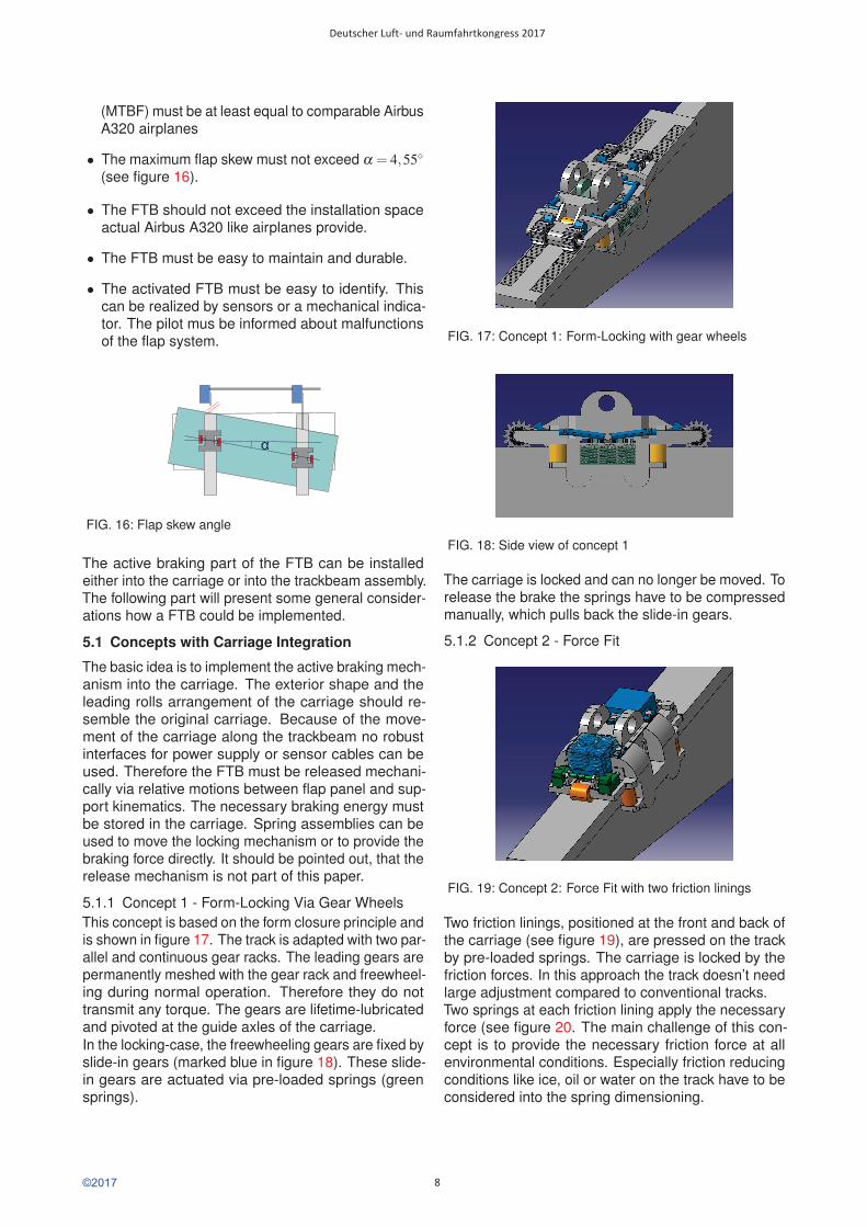
5.1.1 Concept 1 - Form-Locking Via Gear WheelsThis concept is based on the form closure principle andis shown in figure 17. The track is adapted with two par-allel and continuous gear racks. The leading gears arepermanently meshed with the gear rack and freewheel-ing during normal operation. Therefore they do nottransmit any torque. The gears are lifetime-lubricatedand pivoted at the guide axles of the carriage.In the locking-case, the freewheeling gears are fixed byslide-in gears (marked blue in figure 18). These slide-in gears are actuated via pre-loaded springs (greensprings).
FIG. 17: Concept 1: Form-Locking with gear wheels
FIG. 18: Side view of concept 1
The carriage is locked and can no longer be moved. Torelease the brake the springs have to be compressedmanually, which pulls back the slide-in gears.
5.1.2 Concept 2 - Force Fit
FIG. 19: Concept 2: Force Fit with two friction linings
Two friction linings, positioned at the front and back ofthe carriage (see figure 19), are pressed on the trackby pre-loaded springs. The carriage is locked by thefriction forces. In this approach the track doesn’t needlarge adjustment compared to conventional tracks.Two springs at each friction lining apply the necessaryforce (see figure 20. The main challenge of this con-cept is to provide the necessary friction force at allenvironmental conditions. Especially friction reducingconditions like ice, oil or water on the track have to beconsidered into the spring dimensioning.
©2017
Deutscher Luft- und Raumfahrtkongress 2017
8
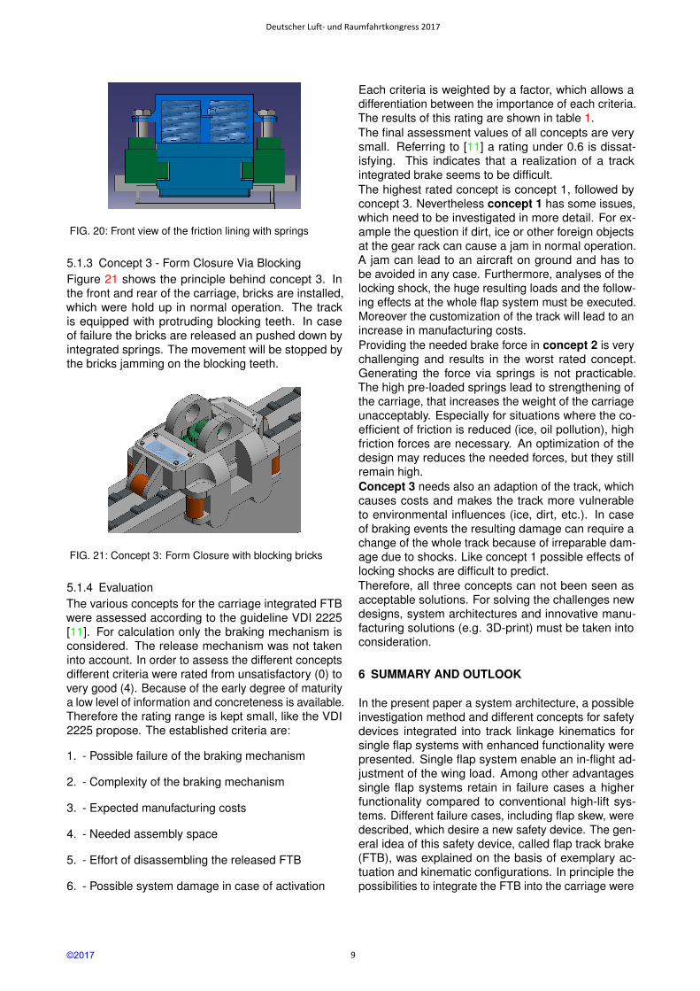
FIG. 20: Front view of the friction lining with springs
5.1.3 Concept 3 - Form Closure Via BlockingFigure 21 shows the principle behind concept 3. Inthe front and rear of the carriage, bricks are installed,which were hold up in normal operation. The trackis equipped with protruding blocking teeth. In caseof failure the bricks are released an pushed down byintegrated springs. The movement will be stopped bythe bricks jamming on the blocking teeth.
FIG. 21: Concept 3: Form Closure with blocking bricks
5.1.4 EvaluationThe various concepts for the carriage integrated FTBwere assessed according to the guideline VDI 2225[11]. For calculation only the braking mechanism isconsidered. The release mechanism was not takeninto account. In order to assess the different conceptsdifferent criteria were rated from unsatisfactory (0) tovery good (4). Because of the early degree of maturitya low level of information and concreteness is available.Therefore the rating range is kept small, like the VDI2225 propose. The established criteria are:
1. - Possible failure of the braking mechanism
2. - Complexity of the braking mechanism
3. - Expected manufacturing costs
4. - Needed assembly space
5. - Effort of disassembling the released FTB
6. - Possible system damage in case of activation
Each criteria is weighted by a factor, which allows adifferentiation between the importance of each criteria.The results of this rating are shown in table 1.The final assessment values of all concepts are verysmall. Referring to [11] a rating under 0.6 is dissat-isfying. This indicates that a realization of a trackintegrated brake seems to be difficult.The highest rated concept is concept 1, followed byconcept 3. Nevertheless concept 1 has some issues,which need to be investigated in more detail. For ex-ample the question if dirt, ice or other foreign objectsat the gear rack can cause a jam in normal operation.A jam can lead to an aircraft on ground and has tobe avoided in any case. Furthermore, analyses of thelocking shock, the huge resulting loads and the follow-ing effects at the whole flap system must be executed.Moreover the customization of the track will lead to anincrease in manufacturing costs.Providing the needed brake force in concept 2 is verychallenging and results in the worst rated concept.Generating the force via springs is not practicable.The high pre-loaded springs lead to strengthening ofthe carriage, that increases the weight of the carriageunacceptably. Especially for situations where the co-efficient of friction is reduced (ice, oil pollution), highfriction forces are necessary. An optimization of thedesign may reduces the needed forces, but they stillremain high.Concept 3 needs also an adaption of the track, whichcauses costs and makes the track more vulnerableto environmental influences (ice, dirt, etc.). In caseof braking events the resulting damage can require achange of the whole track because of irreparable dam-age due to shocks. Like concept 1 possible effects oflocking shocks are difficult to predict.Therefore, all three concepts can not been seen asacceptable solutions. For solving the challenges newdesigns, system architectures and innovative manu-facturing solutions (e.g. 3D-print) must be taken intoconsideration.
6 SUMMARY AND OUTLOOK
In the present paper a system architecture, a possibleinvestigation method and different concepts for safetydevices integrated into track linkage kinematics forsingle flap systems with enhanced functionality werepresented. Single flap system enable an in-flight ad-justment of the wing load. Among other advantagessingle flap systems retain in failure cases a higherfunctionality compared to conventional high-lift sys-tems. Different failure cases, including flap skew, weredescribed, which desire a new safety device. The gen-eral idea of this safety device, called flap track brake(FTB), was explained on the basis of exemplary ac-tuation and kinematic configurations. In principle thepossibilities to integrate the FTB into the carriage were
©2017
Deutscher Luft- und Raumfahrtkongress 2017
9
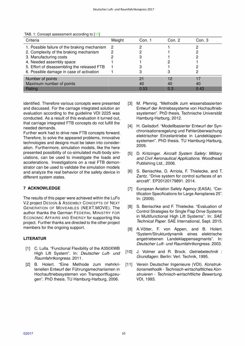
TAB. 1: Concept assessment according to [11]
Criteria Weight Con. 1 Con. 2 Con. 3
1. Possible failure of the braking mechanism 2 2 1 22. Complexity of the braking mechanism 2 2 1 23. Manufacturing costs 2 3 1 24. Needed assembly space 1 1 2 15. Effort of disassembling the released FTB 1 3 1 26. Possible damage in case of activation 1 3 3 2
Number of points 21 12 17Maximum number of points 40 40 40Rating 0.53 0.3 0.43
identified. Therefore various concepts were presentedand discussed. For the carriage integrated solution anevaluation according to the guideline VDI 2225 wasconducted. As a result of this evaluation it turned out,that carriage integrated FTB concepts do not fulfill theneeded demands.Further work had to drive new FTB concepts forward.Therefore, to solve the appeared problems, innovativetechnologies and designs must be taken into consider-ation. Furthermore, simulation models, like the herepresented possibility of co-simulated multi-body sim-ulations, can be used to investigate the loads andaccelerations. Investigations on a real FTB demon-strator can be used to validate the simulation modelsand analyze the real behavior of the safety device indifferent system states.
7 ACKNOWLEDGE
The results of this paper were achieved within the LuFoV.2 project DESIGN & ASSEMBLY CONCEPTS OF NEXTGENERATION OF MOVEABLES (NEXT.MOVE). Theauthor thanks the German FEDERAL MINISTRY FORECONOMIC AFFAIRS AND ENERGY for supporting thisproject. Further thanks are directed to the other projectmembers for the ongoing support.
LITERATUR
[1] C. Lulla. “Functional Flexibility of the A350XWBHigh Lift System”. In: Deutscher Luft- undRaumfahrtkongress. 2011.
[2] B. Holert. “Eine Methode zum mehrkri-teriellen Entwurf der Fuhrungsmechanismen inHochauftriebssystemen von Transportflugzeu-gen”. PhD thesis. TU Hamburg-Harburg, 2006.
[3] M. Pfennig. “Methodik zum wissensbasiertenEntwurf der Antriebssysteme von Hochauftrieb-ssystemen”. PhD thesis. Technische UniversitatHamburg-Harburg, 2012.
[4] H. Geilsdorf. “Modellbasierter Entwurf der Syn-chronisationsregelung und Fehleruberwachungelektrischer Einzelantriebe in Landeklappen-systemen”. PhD thesis. TU Hamburg-Harburg,2009.
[5] D. Kritzinger. Aircraft System Safety: Militaryand Civil Aeronautical Applications. WoodheadPublishing Ltd., 2006.
[6] S. Benischke, D. Arriola, F. Thielecke, and T.Zantz. “Drive system for control surfaces of anaircraft”. EP20120179891. 2014.
[7] European Aviation Safety Agency (EASA). “Cer-tification Specifications for Large Aeroplanes 25”.In: (2009).
[8] S. Benischke and F. Thielecke. “Evaluation ofControl Strategies for Single Flap Drive Systemsin Multifunctional High Lift Systems”. In: SAETechnical Paper. SAE International, Sept. 2015.
[9] A.Votter, F. von Appen, and B. Holert.“System/Strukturdynamik eines elektrischeangetriebenen Landeklappensegmants”. In:Deutscher Luft- und Raumfahrtkongress. 2003.
[10] J. Volmer and R. Brock. Getriebetechnik :Grundlagen. Berlin: Verl. Technik, 1995.
[11] Verein Deutscher Ingenieure (VDI). Konstruk-tionsmethodik - Technisch-wirtschaftliches Kon-struieren - Technisch-wirtschftliche Bewertung.VDI, 1993.
©2017
Deutscher Luft- und Raumfahrtkongress 2017
10


![Concepts for a Safety Device in Conventional Track-Linkage ... · the angular position of the shaft. The FPPU is used for control and monitoring functions [4]. The Asym-metric Position](https://img.pdfslide.us/doc/110x75/5d5fc24188c993c53c8b8ad3/concepts-for-a-safety-device-in-conventional-track-linkage-the-angular-position.jpg)