Embed Size (px)
Citation preview
Bachelor Thesis
Conception and Development of a
Threat Modeling Tool
By
Tobias Reski
In
Medien und Informationswesen
Faculty
Medien und Informationswesen
Academic Supervision:
Prof. Dr. Andreas Schaad
Second Examiner:
Dipl.-Ing. Oliver Vauderwange
23.11.2018 – 23.02.2019
Hochschule Offenburg
I
Abstract
The development of secure software systems is of ever-increasing importance. While
software companies often invest large amounts of resources into the upkeeping and general
security properties of large-scale applications when in production, they appear to neglect
utilizing threat modeling in the earlier stages of the software development lifecycle. When
applied during the design phase of development, and continuously during development
iterations, threat modeling can help in following a “Security by Design” approach. This
approach allows issues relating to IT security to be found early during development,
reducing the need for later improvement – and thus saving resources in the long term. In
this thesis the current state of threat modeling is investigated. Based on this analysis,
requirements for a new tool are derived. These requirements are then used to develop a
new tool, called OVVL, which utilizes all main components of current threat modeling
methodologies, as well as functionality not available in existing solutions. After documenting
the development process and OVVL in general, this newly developed tool is used to conduct
two case studies in the field of e-commerce and IoT.
II
Acknowledgements
Many people helped in shaping this thesis, and their support benefited this project greatly.
To begin with, I want to thank my supervisor, Prof. Andreas Schaad, for his patient support,
guidance, and advice he provided throughout the preparation of this thesis. His expertise in
the field and continuous questions helped me greatly in understanding the many different
concepts I came across during my research. Additionally, I would also like to thank the rest of
the team, Janick Born and Benedikt Balint, whose skills and ideas were a crucial factor in
making this project a reality. The combined effort in our team made the development and
documentation a very comfortable environment to work in. Finally, I also want to thank Prof.
Ralf Reski, for taking the time for proofreading, valuable suggestions and guiding me in
writing less, saying more.
III
Table of Contents
Abstract .................................................................................................................................................... I
Acknowledgements ................................................................................................................................. II
List of Figures ........................................................................................................................................... 1
List of Tables ............................................................................................................................................ 3
1. Introduction ......................................................................................................................................... 4
2. Background Threat and Risk Assessment ............................................................................................ 5
2.1 Threat Modeling ............................................................................................................................ 6
2.2 STRIDE ............................................................................................................................................ 8
2.3 CPE, CVE, and CVSS ...................................................................................................................... 10
2.4 Existing Threat Modeling Tools ................................................................................................... 11
2.4.1 Microsoft Threat Modeling Tool (TMT) ................................................................................ 11
2.4.2 OWASP Threat Dragon ......................................................................................................... 13
2.4.3 ThreatModeler, IriusRisk and securiCAD .............................................................................. 14
3. Open Weakness and Vulnerability Modeler ..................................................................................... 16
3.1 Scope ........................................................................................................................................... 16
3.2 Team structure ............................................................................................................................ 17
3.3 MVP Roadmap ............................................................................................................................. 17
3.4 Foundation .................................................................................................................................. 19
3.4.1 Current Threat Modeling State ............................................................................................ 19
3.4.2 Requirements ....................................................................................................................... 19
3.4.3 Feature List ........................................................................................................................... 20
3.5 Concept........................................................................................................................................ 22
3.5.1 3-A-Model ............................................................................................................................. 22
3.5.2 Conceptual Data Model ........................................................................................................ 23
3.5.3 Design ................................................................................................................................... 26
3.6 Implementation ........................................................................................................................... 27
3.6.1 Technology Stack .................................................................................................................. 28
3.6.2 Deployment Architecture ..................................................................................................... 31
3.6.3 Class Structure and Data Transfer ........................................................................................ 31
3.6.4. Threat and Vulnerability Analysis ........................................................................................ 33
3.6.5 State Management ............................................................................................................... 34
3.6.6 GitHub Version Control ........................................................................................................ 35
3.6.7 Hosting and Continuous Integration .................................................................................... 37
3.7 MVP Overview ............................................................................................................................. 37
IV
3.7.1 Implementation of the Conceptual Data Model .................................................................. 37
3.7.2 Feature Stack ........................................................................................................................ 38
3.7.3 MVP Feature Showcase ........................................................................................................ 39
4. Case Studies ....................................................................................................................................... 44
4.1 System X ...................................................................................................................................... 44
4.2 IoT System ................................................................................................................................... 48
4.3 Discussion of the Case Studies in Respect to the Initial Requirements ...................................... 50
4.4 Modeling the Case Studies in Microsoft’s TMT ........................................................................... 51
5. Discussion .......................................................................................................................................... 53
6. Conclusion ......................................................................................................................................... 57
7. References ......................................................................................................................................... 58
Appendix A: Design Guideline OVVL ..................................................................................................... 61
Appendix B: System X Modeled in OVVL ............................................................................................... 72
Appendix C: System X Modeled in Microsoft’s TMT ............................................................................. 73
Appendix D: Comparison of CPE and CVE queries loading times in OVVL and the NVD [20] .............. 74
Declaration of Independent Work ........................................................................................................ 76
1
List of Figures
Figure 1: Risk Matrix. Modified after [4]. ................................................................................................ 6
Figure 2: DFD of a fictitious software architecture using "Microsoft Threat Modeling Tool" [10]. ........ 7
Figure 3: Microsoft Threat Model Tool design view [10]. .................................................................... 12
Figure 4: OWASP Threat Dragon desktop application DFD view. ......................................................... 14
Figure 5: OVVL Logo. ............................................................................................................................. 16
Figure 6: Roadmap outlining the development process of OVVL's MVP. ............................................ 18
Figure 7: The 3-A-Model showcasing OVVL’s data processing.............................................................. 22
Figure 8: UML diagram of OVVL’s Conceptual Data Model. ................................................................. 23
Figure 9: Color definition of the interactor element in each of its possible states. .............................. 26
Figure 10: Abstracted component structure of our Angular application. ............................................. 29
Figure 11: OVVL deployment architecture. ........................................................................................... 31
Figure 12: Abstracted conversion of a "Process" to a "ProcessDTO". The datatypes of the displayed
properties either follow the TypeScript notation or consist of custom interfaces. ............................. 32
Figure 13: DTO collection in a "ThreatModelDTO" object. ................................................................... 32
Figure 14: Transfer of the "ThreatModelDTO" to the backend. The properties of the corresponding
“ThreatModel” Java object can be accessed by auto-generated getter and setter methods. ............. 32
Figure 15: "Threat" class diagram. ........................................................................................................ 33
Figure 16: Basic "Model-View-ViewModel“ design pattern applied to abstract Angular application. . 34
Figure 17: Basic communication within an Angular application implementing Redux. ........................ 35
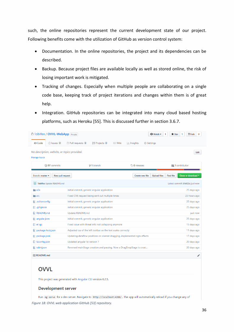
Figure 18: OVVL web application GitHub [53] repository. .................................................................... 36
Figure 19: Parts of the Conceptual Data Model discussed in section 3.5.2 currently implemented in
the MVP. ................................................................................................................................................ 38
Figure 20: OVVL working space. ............................................................................................................ 39
Figure 21: DFD of an arbitrary software system, created with OVVL. .................................................. 40
Figure 22: Zoomed in view of an arbitrary DFD in OVVL. ...................................................................... 40
Figure 23: Specification of a process in OVVL. ...................................................................................... 41
Figure 24: Updated DFD elements in OVVL. .......................................................................................... 41
Figure 25: CPE-Selection in OVVL. ......................................................................................................... 41
Figure 26: Found STRIDE threats within an arbitrary system in OVVL. ................................................. 42
Figure 27: Highlighting of DFD elements and displaying of additional information after a STRIDE
threat has been selected in OVVL. ........................................................................................................ 42
Figure 28: Found CVE-References ranked by their CVSS impact score in OVVL. .................................. 43
Figure 29: Highlighting of a DFD element and displaying of additional information after a CVE-
Reference has been selected in OVVL. .................................................................................................. 43
Figure 30: Technical Deployment of System X web application [58, p. 9]. ........................................... 45
Figure 31: Zoomed in view of System X's DFD, created in OVVL. ......................................................... 45
Figure 32: Set properties and selected CPE in the Apache Web Server specified in System X's
documentation. ..................................................................................................................................... 46
Figure 33: Highlighted spoofing threat in System X. ............................................................................. 46
Figure 34: Oracle Database affected by two vulnerabilities. ................................................................ 47
Figure 35: DFD of the IoT system discussed in section 4.2. .................................................................. 49
Figure 36: Threat analysis of System X in OVVL (left) and Microsoft's TMT (right) reports 62 threats in
both tools. Both DFD’s set the same properties. .................................................................................. 52
Figure 37: System X (Section 4.1) modeled in OVVL. ............................................................................ 72
Figure 38: System X (Section 4.1) modeled in Microsoft's TMT. ........................................................... 73
Figure 39: Loading time of the CPE query "Windows 10 64-bit" in OVVL. ............................................ 74
2
Figure 40: Loading time of the CVE query of the CPE of "Windows 10 64-bit" in OVVL. ...................... 74
Figure 41: Loading time of the CPE query "Windows 10 64-bit" in the NVD [19]. ................................ 75
Figure 42: Loading time of the CVE query of the CPE of "Windows 10 64-bit" in the NVD [19]. .......... 75
3
List of Tables
Table 1: STRIDE to DFD elements matrix [16, p. 1105]. .......................................................................... 9
Table 2: OVVL Feature Prioritization and Comparison. ......................................................................... 20
Table 3: Comparison of the loading times of both the “Windows 10 64-bit” CPE and the derived CVE
search query between OVVL and the NVD [20]. Values are displayed in milliseconds (ms) and rounded
to the nearest integer. .......................................................................................................................... 55
4
1. Introduction
With the globalization of software infrastructure and the resulting increase in user numbers,
designing and developing secure software and software architectures is of ever-increasing
importance. When neglected, overlooked errors can result in severe financial and
reputational losses. Because the sophistication of attacks is increasing, designing software
stacks with security concerns already in mind from the beginning onwards is crucial. In this
context, threat modeling can be a useful tool for conducting an informed analysis of the
security risks inherent to a software system. In an ideal setting, threat modeling is utilized in
parallel to the development lifecycle. While many resources detailing the threat modeling
process are available, free tools offering threat modeling support are few and far between,
as well as lacking in several areas. As a result, integrating threat modeling in the
development process might seem for many developers as tedious, unnecessary, and
generally hard to do.
Improving the current state of threat modeling and lowering the barrier of entry for its
integration in software projects is the goal of this thesis. In this context, the lacking areas of
available tools are analyzed and suggestions for possible improvements are made.
Additionally, the suggested improvements are showcased by means of implementing them
in form of a new threat modeling tool.
This thesis is split into three parts. Initially, we provide a general overview over threat
modeling. Here, the general background behind risk assessment in symbiosis with threat
modeling is given. Additionally, existing tools are analyzed in context of their feature palette
and design. The second part specifies its scope and the structure of the whole project further
and continues with the discussion of the development of a new tool. This discussion builds
onto the analysis of the first part and includes derived requirements for a new tool, its
general concept and implementation structure. Also, an overview over the new tool in its
current development state is given. In the third part, the new tool is utilized to conduct two
case studies, thus evaluating how the new tool can aid in the development process.
5
2. Background Threat and Risk Assessment
Designing and developing secure software architectures and applications is of increasing
importance. “Security by Design” is an approach modern software development should
adopt as part of a dedicated Secure Development Lifecycle (SDLC). In order to ensure that a
software system cannot be exploited once it is in production, implementing dedicated threat
and risk assessment processes during the overall system lifecycle is crucial.
Risk assessment is meant to provide a systematic and structured approach to identifying and
evaluating possible threats and risks a system faces. By using this approach, the impact of a
potential threat on a system can be estimated [1, pp. 1-21]. Generally, the basic concepts
for a software risk assessment can be broken down into the following artefacts[2] :
• Asset. Anything that needs to be protected within a system is described as an asset.
Assets can be assigned with a value to assess the impact of a system compromise.
• Threat. The potential circumstance in which an asset and thus a system can be
compromised.
• Vulnerability. A vulnerability describes a weakness in an asset, which, if exploited,
may give rise to a threat.
• Risk. The possibility of losing something of value.
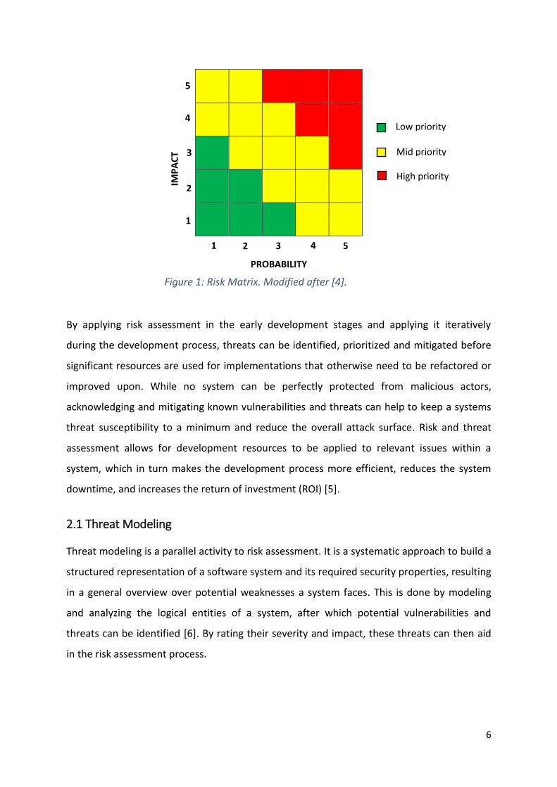
To calculate the risks a system faces, the impact and probability of a threat need to be
defined. The impact describes the effect on the software system, should a threat be realized,
while the probability describes the likelihood of the threat realization. Defining these factors
is often guesswork, but doing so allows for the derivation of the following formula [3]:
𝐼𝑚𝑝𝑎𝑐𝑡 ∗ 𝑃𝑟𝑜𝑏𝑎𝑏𝑖𝑙𝑖𝑡𝑦 = 𝑅𝑖𝑠𝑘
Mapping this formula to a risk-matrix visualizes how risks – and thus threats – could be
prioritized (Figure 1):
6
By applying risk assessment in the early development stages and applying it iteratively
during the development process, threats can be identified, prioritized and mitigated before
significant resources are used for implementations that otherwise need to be refactored or
improved upon. While no system can be perfectly protected from malicious actors,
acknowledging and mitigating known vulnerabilities and threats can help to keep a systems
threat susceptibility to a minimum and reduce the overall attack surface. Risk and threat
assessment allows for development resources to be applied to relevant issues within a
system, which in turn makes the development process more efficient, reduces the system
downtime, and increases the return of investment (ROI) [5].
2.1 Threat Modeling
Threat modeling is a parallel activity to risk assessment. It is a systematic approach to build a
structured representation of a software system and its required security properties, resulting
in a general overview over potential weaknesses a system faces. This is done by modeling
and analyzing the logical entities of a system, after which potential vulnerabilities and
threats can be identified [6]. By rating their severity and impact, these threats can then aid
in the risk assessment process.
Figure 1: Risk Matrix. Modified after [4].
PROBABILITY
IMP
AC
T
Low priority
Mid priority
High priority
1 2
2
1
3
3
4
4
5
5
7
One possible way to build a threat model is by applying the following steps [6] [7]:
1. Decomposing an application into modular entities by identifying its assets (e.g. Web-
Application, Database).
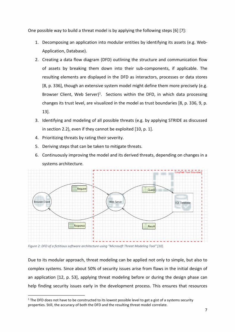
2. Creating a data flow diagram (DFD) outlining the structure and communication flow
of assets by breaking them down into their sub-components, if applicable. The
resulting elements are displayed in the DFD as interactors, processes or data stores
[8, p. 336], though an extensive system model might define them more precisely (e.g.
Browser Client, Web Server)1. Sections within the DFD, in which data processing
changes its trust level, are visualized in the model as trust boundaries [8, p. 336, 9, p.
13].
3. Identifying and modeling of all possible threats (e.g. by applying STRIDE as discussed
in section 2.2), even if they cannot be exploited [10, p. 1].
4. Prioritizing threats by rating their severity.
5. Deriving steps that can be taken to mitigate threats.
6. Continuously improving the model and its derived threats, depending on changes in a
systems architecture.
[11]
Due to its modular approach, threat modeling can be applied not only to simple, but also to
complex systems. Since about 50% of security issues arise from flaws in the initial design of
an application [12, p. 53], applying threat modeling before or during the design phase can
help finding security issues early in the development process. This ensures that resources
1 The DFD does not have to be constructed to its lowest possible level to get a gist of a systems security properties. Still, the accuracy of both the DFD and the resulting threat model correlate.
Figure 2: DFD of a fictitious software architecture using "Microsoft Threat Modeling Tool" [10].
8
can be assigned more effectively during the actual development, since it is more cost
efficient to resolve issues before a system is in development then after deployment.
Identifying threats early also helps to develop “realistic and meaningful security
requirements” [10, p. 1].
2.2 STRIDE
STRIDE is a threat modeling approach developed by Microsoft [13] and is based on the
assumption, that threats software architectures are susceptible to can be clustered [14, p.
5]. The STRIDE model divides IT-Security threats into the following 6 categories [13, p. 1].
Spoofing of user identity
Spoofing happens when an attacker breaches a user’s authentication data, either through
having access to personal information or through being able to replay the authentication
procedure [13, p. 2]. By impersonating users with extensive access rights to a system, an
attacker might be able to compromise the system in many different aspect (e.g. access and
manipulation of data, weakening of the security structure).
An example of a spoofing threat is not using encrypted authentication and/or authorization
protocols. User credentials can be intercepted by an attacker, who in return is able to
impersonate the user. A strong, encrypted authentication system can prevent this type of
threat.
Tampering with data
Tampering is a threat which describes an attacker being able to manipulate “system or user
data with or without detection” [13, p. 3]. These types of attacks can range from changing
the price of an item in an online-shop to deleting a production database. Similar to
addressing spoofing threats, a software system could use encryption and digital signatures in
order to prevent tampering.
Repudiation
Repudiation describes an attacker not being able to be traced or an attack not being
attributable to them. It is not an attack itself, but the manipulation of data in order to hide
traces of an attack. For example, an attacker might be able to spoof his identity when
9
performing an unauthorized action and/or tamper with security logs in order to cover up an
attack [13, p. 4].
Information disclosure (privacy breach)
An information disclosure threat is realized when a perpetrator is able to gain access to
confidential data. In this case, data can be anything from files to network traffic. A tampering
threat differs from a spoofing threat in that an attacker can access data directly [13, p. 9].
Denial of Service (D.o.S.)
Denial of Service describes a service being unavailable due to a lock up of resources as a
result of an attack. These threats can be hard to prevent, since they are usually realized by
flooding the target system with requests from different physical locations [15], e.g. by the
use of so-called “botnets”.
Elevation of privilege
Elevation of privilege describes an attacker being able to gain privileged access, which in
return gives them the ability to compromise the entire system [13, p. 6]. This is especially
dangerous if the perpetrator can gain access without detection. When an elevation of
privilege threat is realized, an “attacker has effectively penetrated all system defenses and
becomes part of the trusted system” [13, p. 6].
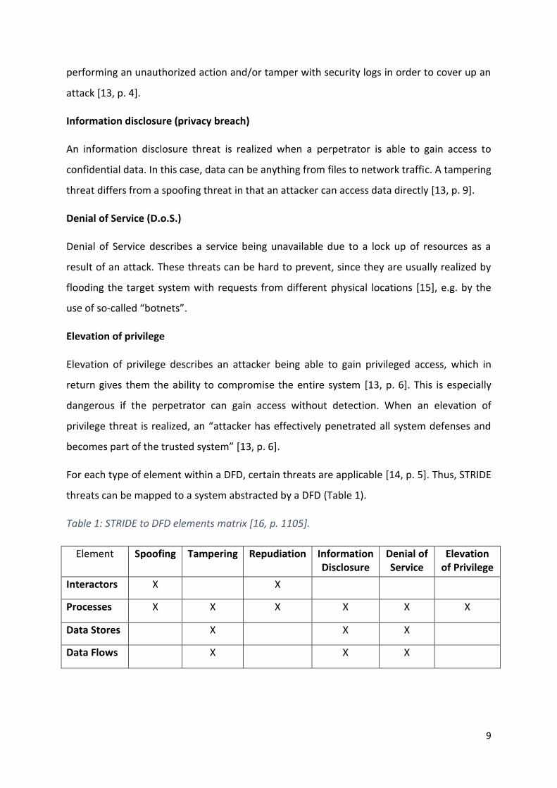
For each type of element within a DFD, certain threats are applicable [14, p. 5]. Thus, STRIDE
threats can be mapped to a system abstracted by a DFD (Table 1).
Table 1: STRIDE to DFD elements matrix [16, p. 1105].
Element Spoofing Tampering Repudiation Information Disclosure
Denial of Service
Elevation of Privilege
Interactors X X
Processes X X X X X X
Data Stores X X X
Data Flows X X X
10
It must be noted that the aforementioned mapping of STRIDE to DFD elements is applied to
generic elements. When applied to more specific elements and communication scenarios,
this matrix (Table 1) should be fine-tuned [14, p. 5]; e.g. a data store might not always be
susceptible to denial of service attacks, but to repudiation when implementing a log service.
STRIDE, when fine-tuned and used in combination with an extensive system model, aids in
giving a security overview over a software system. While it does not cover every possible
attack explicitly, its more general approach at identifying threats is a good starting point for
identifying the security weaknesses of a software system [14, p. 1].
2.3 CPE, CVE, and CVSS
While STRIDE is used to gain a general threat overview, knowing about explicit software
vulnerabilities improves a threat model further. Elements in a DFD can be defined more
clearly by specifying a certain software make, for which information about known
vulnerabilities is stored and accessible in public databases. Found vulnerabilities can then be
mitigated before they are exploited.
CPE
CPE stands for “Common Platform Enumeration” and is a “structured naming scheme for
information technology systems, software and packages” [17]. CPE’s are meant to name
software products in a standardized manner. One CPE can be linked to only one Software.
For example, “Windows 10 1607 64-bit” CPE is defined as [18]:
𝑐𝑝𝑒: 2.3: 𝑜: 𝑚𝑖𝑐𝑟𝑜𝑠𝑜𝑓𝑡: 𝑤𝑖𝑛𝑑𝑜𝑤𝑠_10: 1607:∗:∗:∗:∗:∗: 𝑥64:∗
For each CPE, known software vulnerabilities can be found in the form of CVE-References
(“Common Vulnerabilities and Exposures” [19]).
CVE
CVE is a standardized system for referencing known software vulnerabilities, as provided by
the NVD [20]. CVE-References include, amongst other things, a summary of the vulnerability,
the date the vulnerability was published, one or multiple CPE-References and a CVSS
(“Common Vulnerability Scoring System” [21]) score. A CVE-Reference might be named in
the following way [22]:
𝐶𝑉𝐸 − 2018 − 8505
11
CVSS
CVSS “provides a way to capture the principal characteristics of a vulnerability and produces
a numerical score reflecting its severity” [21]. This score describes the impact of the
vulnerability. The severity of a vulnerability is based on aspects like its attack complexity or
its impact on integrity and confidentiality. Each CVE-Reference includes a CVSS score, which
enables the ranking of vulnerabilities.
2.4 Existing Threat Modeling Tools
Many aspects of threat modeling can be automated or supported by tools, which can make
it easier to integrate threat modeling into the development lifecycle. During the course of
this project, we performed an extensive (informal) analysis of the free existing tools,
focusing on their features and on their user experience (UX) design. By doing so, we aim to
derive requirements for our own tool, and thus offer an approach to threat modeling which
significantly improves upon the existing tools. Currently, there are two free and several
commercial tools available.
2.4.1 Microsoft Threat Modeling Tool (TMT)
Microsoft provides a free tool in the form of a Windows desktop application [11]. Its threat
analysis is based on the STRIDE methodology. TMT’s main features include [23]:
• Extensive documentation.
• Creating DFDs manually.
• Setting properties of DFD elements and adding custom properties.
• Listing potential STRIDE threats following an automated DFD analysis.
• Creating custom threats.
• Manually prioritizing threats.
• Exporting a CSV file of found threats.
• Creating a threat report in form of a HTML file
12
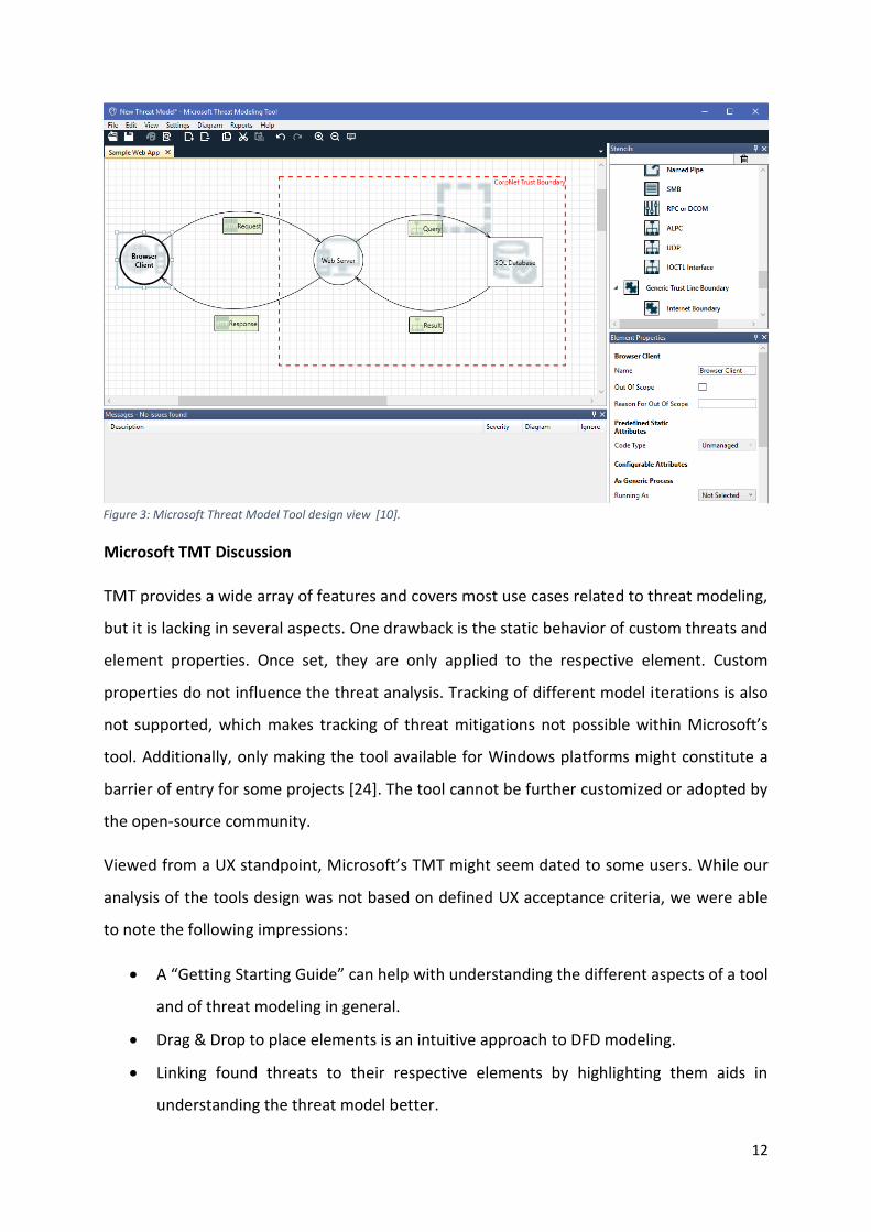
Microsoft TMT Discussion
TMT provides a wide array of features and covers most use cases related to threat modeling,
but it is lacking in several aspects. One drawback is the static behavior of custom threats and
element properties. Once set, they are only applied to the respective element. Custom
properties do not influence the threat analysis. Tracking of different model iterations is also
not supported, which makes tracking of threat mitigations not possible within Microsoft’s
tool. Additionally, only making the tool available for Windows platforms might constitute a
barrier of entry for some projects [24]. The tool cannot be further customized or adopted by
the open-source community.
Viewed from a UX standpoint, Microsoft’s TMT might seem dated to some users. While our
analysis of the tools design was not based on defined UX acceptance criteria, we were able
to note the following impressions:
• A “Getting Starting Guide” can help with understanding the different aspects of a tool
and of threat modeling in general.
• Drag & Drop to place elements is an intuitive approach to DFD modeling.
• Linking found threats to their respective elements by highlighting them aids in
understanding the threat model better.
Figure 3: Microsoft Threat Model Tool design view [10].
13
• The different DFD elements and their sub-components are displayed in one long, by
default unfolded list. This can make it hard to find certain elements during the
modeling process.
• The working area seems to be boxed in by too much information and settings.
• A lot of text is used to explain features and properties. While this generally helps with
understanding certain aspects of the tool, it can be confusing to get an overview over
the current process.
• Many sub-windows take up space unnecessarily by sometimes containing no
information. This happens when a feature usually managed from a certain window is
currently not in use.
• Unclear, repeating icons and an unintuitive navigation structure can make it hard to
create a threat model in a timely manner.
• While multiple diagrams can be created in one project file, they cannot be linked to
construct complex systems.
• Changing between design and analysis view is not intuitive.
The fact that Microsoft’s TMT offers more features compared to OWASP’s Threat Dragon
(discussed in section 2.4.2), made its design and feature analysis crucial for deriving
requirements for our tool. These requirements are discussed in section 3.4.2.
2.4.2 OWASP Threat Dragon
As described in its documentation [25], Threat Dragon is an open-source threat modeling
tool developed by OWASP and currently in the early stages of development. It is freely
available in the form of a web application and as a standalone desktop app for both
Windows and MacOS. Its main features include [25]:
• Creating DFDs manually.
• Setting properties of DFD elements.
• Adding custom STRIDE threats.
• Manually prioritizing threats.
• Linking threat models to GitHub Repositories.
14
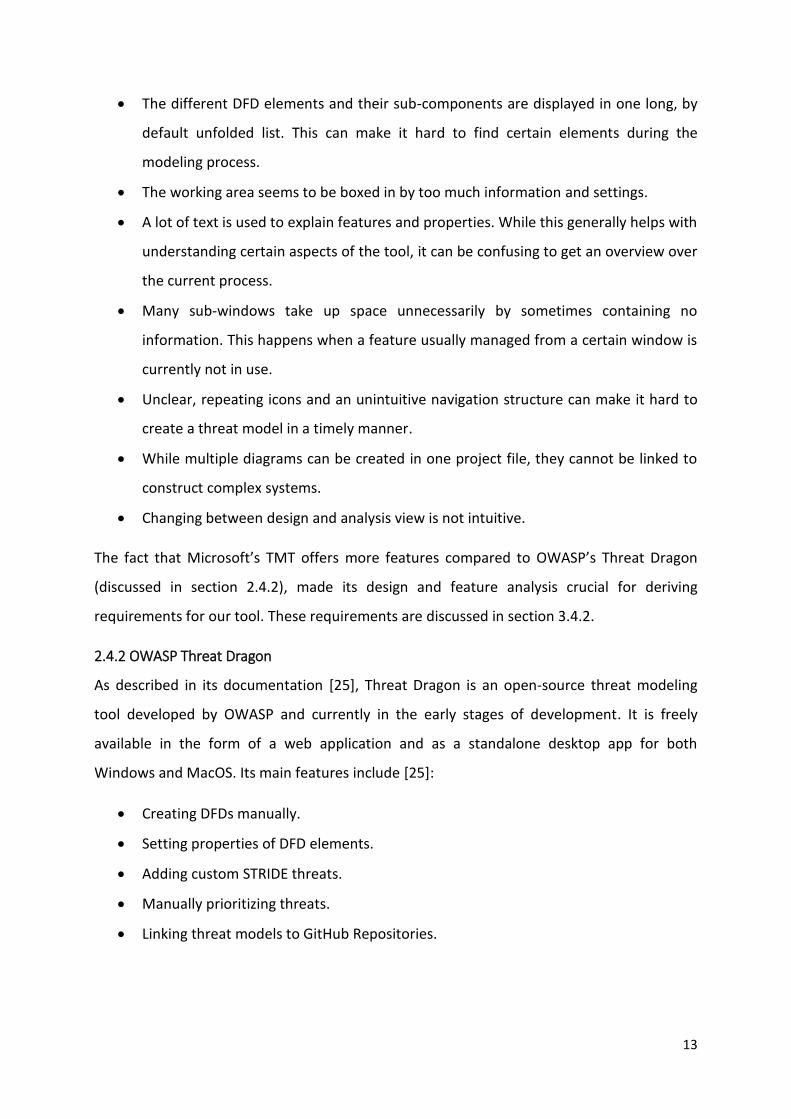
OWASP Threat Dragon Discussion
Being open source and platform independent, Threat Dragon is a tool that could be
integrated in most development lifecycles without much effort. Its clean design
implementation aids in giving a clear overview over architectures of varying complexity.
Threat Dragon’s community driven development approach constitutes a few major
drawbacks when it comes to feature availability. Compared to Microsoft’s TMT, Threat
Dragon currently offers neither automatic threat analysis, exporting of threat data, nor the
automatic generation of threat reports. DFD element properties are currently very limited
and no custom properties can be set. With Threat Dragon’s last commit to its master branch
being January 20, 2018 [26], its ambitious goals defined in the roadmap still seem far away
from completion [27]. In its current state, Threat Dragon is still missing several key features
for it to be considered a valid tool for threat modeling.
2.4.3 ThreatModeler, IriusRisk and securiCAD
ThreatModeler [28], IriusRisk [29] and securiCAD [30] are enterprise software solutions
offering risk and threat assessment on a larger scale. Since neither of these tools are
available for free, we were not able to do an extensive analysis of these applications, though
their respective websites give an overview over their features [28–30]. Compared to
Microsoft’s TMT and Threat Dragon, these tools offer a wider array of functionality, like
complex diagram creation, ticket creation for agile teams, multiple threat analysis options
and customer support.
Figure 4: OWASP Threat Dragon desktop application DFD view.
15
ThreatModeler, IriusRisk and securiCAD Discussion
While these extensive features can be immensely valuable for large software projects, we
think that it might cause threat modeling to be viewed as a separate project, instead of it
accompanying the usual development lifecycle – which, combined with their commercial
nature, might make it hard to justify integrating these tools into software projects developed
by smaller teams. We want to follow a different approach and offer a lightweight tool with
the most crucial features for threat modeling. By doing so, we want to make threat
modeling accessible for smaller teams and projects, as well as big projects, where a threat
analysis can be used as a starting point for further risk assessment.
16
3. Open Weakness and Vulnerability Modeler
3.1 Scope
In the context of this thesis, the following goals had to be achieved:
1. Analysis of the current threat modeling state, including the comparison of existing
Threat Modeling tools.
2. Deriving requirements for a new threat modeling tool, which we call “Open
Weakness and Vulnerability Modeler” (OVVL)2.
3. Deciding on a feature list for OVVL, including features that are not offered by other
tools.
4. Development of OVVL as a “Minimum Viable Product” (MVP), which implements the
core features.
5. Analyzing how OVVL utilizes threat modeling, aiding in the development process.
When viewing the project as a whole, its scope can be divided into two sections:
Development of an MVP and the development of the full product. As such, the whole project
spans further than the context of this thesis, during which the MVP is built. While the MVP
does not implement every feature required for the final product, it still can be considered a
working prototype for which valuable user feedback can be acquired. The development of
the final product can then respond to the feedback, while building upon the foundation
created by the MVP.
Because this thesis lays the groundwork for the actual product, the discussion in the
following sections is not limited to only the scope of the MVP. Some aspects, such as the
base requirements discussed in section 3.4.2 and the feature list discussed in section 3.4.3,
are relevant for the development continuing after the completion of this thesis as well. Still,
the main focus of this thesis is the MVP development. Thus, when discussing OVVL in the
following sections, generally the MVP is referred to.
2 The VV stands for a W and V. “Open Weakness and Vulnerability Modeler”.
Figure 5: OVVL Logo.
17
3.2 Team structure
OVVL was designed and built in a team effort. The team was composed of:
• A project lead coordinating the project and providing the background knowledge and
industrial expertise.
• One architect (myself) responsible for the development and documentation of the
tool.
• One engineer assisting in the development of the UX and general design.
• One assisting engineer, responsible for the development and documentation of an
additional attack tree modeling tool, later to be integrated into OVVL.
We followed an agile approach throughout the course of this project, in order to ensure the
timely mitigation of issues arising during the development process. This includes the
iterative development of the different aspects of OVVL. During weekly meetings, these
iterations were designed and implemented after elaborate analysis and discussion of the
current development state in relation to the planned feature implementation. By following
this approach, we were able to respond to new requirements arising throughout the project,
while keeping the core concept in mind. In an ideal agile setting, the role of the project lead
should have been split into a product owner and a project manager [31].
3.3 MVP Roadmap
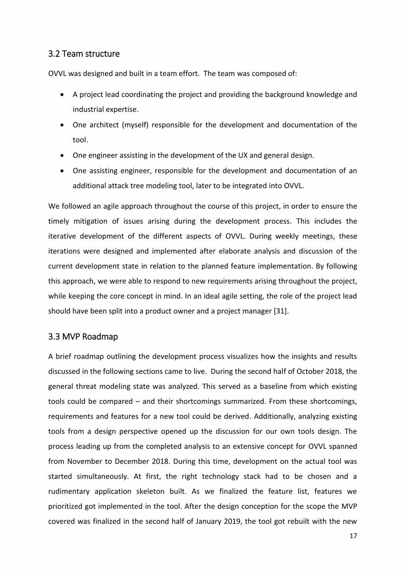
A brief roadmap outlining the development process visualizes how the insights and results
discussed in the following sections came to live. During the second half of October 2018, the
general threat modeling state was analyzed. This served as a baseline from which existing
tools could be compared – and their shortcomings summarized. From these shortcomings,
requirements and features for a new tool could be derived. Additionally, analyzing existing
tools from a design perspective opened up the discussion for our own tools design. The
process leading up from the completed analysis to an extensive concept for OVVL spanned
from November to December 2018. During this time, development on the actual tool was
started simultaneously. At first, the right technology stack had to be chosen and a
rudimentary application skeleton built. As we finalized the feature list, features we
prioritized got implemented in the tool. After the design conception for the scope the MVP
covered was finalized in the second half of January 2019, the tool got rebuilt with the new
18
design, while keeping all the features already implemented. On the 22.01.2019, a
presentation of this thesis outlining our project had to be held. Thus, this date served as a
deadline for constructing a working MVP including the updated design. In February 2019,
case studies utilizing the finished MVP were conducted, bugs present in the tool mitigated,
the tool hosted and finally this thesis submitted. Spanning the whole course of the MVP
development, results gathered were documented in the context of this thesis. These results
are discussed in the following sections.
Continuing forward, we first plan on gathering feedback on the MVP during March 2019.
Based on this feedback, features in our backlog can be re-prioritized, new features can be
added to the backlog, and flawed aspects of current features implementation can be
improved. Development will continue until the end of August 2019, at which time we plan
on delivering a fully functional product.
Figure 6: Roadmap outlining the development process of OVVL's MVP.
19
3.4 Foundation
3.4.1 Current Threat Modeling State
In order to set meaningful requirements for the development of a new threat model tool,
first the present state of the threat modeling field needs to be discussed. Members of
SAFECode, a “global, industry-led effort to identify and promote best practices for
developing and delivering more secure and reliable software, hardware and services” [32, p.
3], came to the following conclusions [32, p. 13]:
• While the demand for useful threat modeling tools is ramping up, existing solutions
do not meet the requirements set by security specialists to a sufficient extend.
• Only a few tools exist and come with a limited guidance availability. This can make it
harder for teams to get started with threat modeling.
• Integrating threat modeling into existing development processes can be challenging.
• Since most security issues only become a concern when exploited, insight gained by
threat modeling might not immediately be seen as useful.
Even though this discussion took place in 2015, the state of threat modeling stayed
seemingly unchanged. While the demand for threat modeling is increasing, only two free
solutions are offered. Microsoft’s TMT and Threat Dragon both are helpful tools for threat
modeling but are missing some essential features. Commercial tools offer a wide range of
features but are harder to integrate into the development lifecycle due to their complexity.
As a result, the growing need for threat modeling is not met in the required extend, an issue
which we want to solve with OVVL.
3.4.2 Requirements
After a careful analysis of the existing tools as discussed in section 2.4, as well as taking the
suggestions from SAFECode [32, pp. 13-14] into account, we derived several high-level
requirements for the final version of OVVL:
• A user must be able to visualize complex communication systems.
• A user must be able to analyze the system for threats and vulnerabilities.
• A user must be able to customize model elements and threats.
• A user must not be limited by their utilized platform.
• Found issues, their mitigation status and model iterations must be traceable.
20
• The system and its threats must be presentable in a visually appealing way.
• The current threat model must be storable both online and offline.
• Multiple users must be able to work on one threat model.
• The threat modeling process must be intuitive, guiding the user when necessary.
These requirements must be met before we consider OVVL to be a fully-fledged product.
Therefore, they serve as our baseline, from which a feature list can be derived. When we
design features or discuss their current implementation of our tool, these requirements are
kept in mind and thus serve as a guide towards the final product.
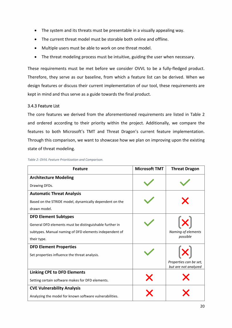
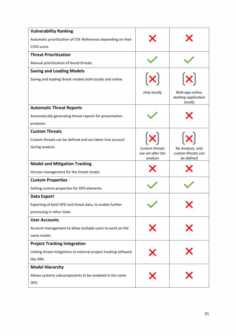
3.4.3 Feature List
The core features we derived from the aforementioned requirements are listed in Table 2
and ordered according to their priority within the project. Additionally, we compare the
features to both Microsoft’s TMT and Threat Dragon’s current feature implementation.
Through this comparison, we want to showcase how we plan on improving upon the existing
state of threat modeling.
Table 2: OVVL Feature Prioritization and Comparison.
Feature Microsoft TMT Threat Dragon
Architecture Modeling
Drawing DFDs.
Automatic Threat Analysis
Based on the STRIDE model, dynamically dependent on the
drawn model.
DFD Element Subtypes
General DFD elements must be distinguishable further in
subtypes. Manual naming of DFD elements independent of
their type.
Naming of elements possible
DFD Element Properties
Set properties influence the threat analysis.
Properties can be set, but are not analyzed
Linking CPE to DFD Elements
Setting certain software makes for DFD elements.
CVE Vulnerability Analysis
Analyzing the model for known software vulnerabilities.
21
Vulnerability Ranking
Automatic prioritization of CVE-References depending on their
CVSS score.
Threat Prioritization
Manual prioritization of found threats.
Saving and Loading Models
Saving and loading threat models both locally and online.
Only locally
Web-app online, desktop application
locally Automatic Threat Reports
Automatically generating threat reports for presentation.
purposes
Custom Threats
Custom threats can be defined and are taken into account
during analysis.
Custom threats are set after the
analysis
No Analysis, only custom threats can
be defined Model and Mitigation Tracking
Version management for the threat model.
Custom Properties
Setting custom properties for DFD elements.
Data Export
Exporting of both DFD and threat data, to enable further
processing in other tools.
User Accounts
Account management to allow multiple users to work on the
same model.
Project Tracking Integration
Linking threat mitigations to external project tracking software
like JIRA.
Model Hierarchy
Allows systems subcomponents to be modeled in the same
DFD.
22
Additionally, we consider a clear focus on UX and design in general to be crucial, since the
different functionalities we plan on offering might otherwise make our application seem too
complex. By following a clean design approach and guiding the user when needed, we aim to
develop a mostly self-explanatory and easy-to-use product. The design of our application is
discussed further in section 3.5.3.
While all features must be implemented before we consider the tool a fully functional
product, our iterative development approach allows us to offer a stable, useable tool
utilizing the features currently implemented. The features implemented in the MVP are
discussed in section 3.7.2.
3.5 Concept
In order to assure a structured and productive development, we decided on a clear concept
before starting development. This allowed us to have a common goal in mind, while working
on different aspects of the tool. The features listed in section 3.4.3 are part of the core
concept, though this section focuses on the actual data and architecture structure. While
concept iterations were developed when necessary, the models discussed in this section
describe the current implementation of OVVL.
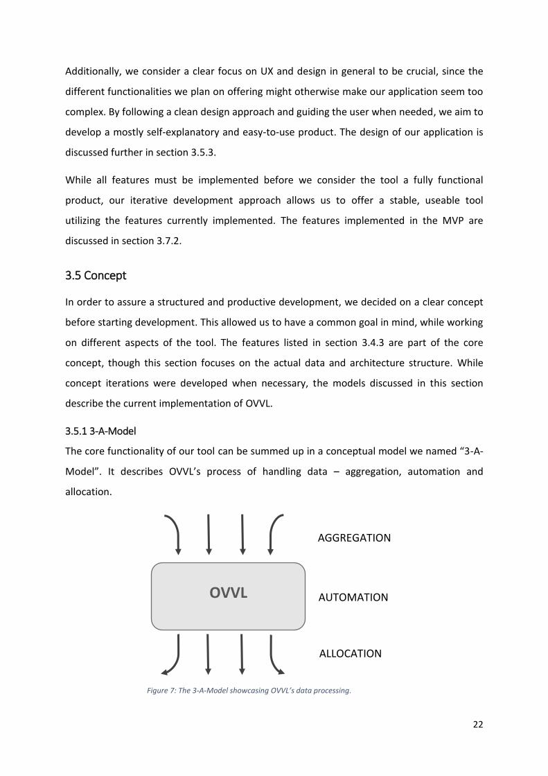
3.5.1 3-A-Model
The core functionality of our tool can be summed up in a conceptual model we named “3-A-
Model”. It describes OVVL’s process of handling data – aggregation, automation and
allocation.
AGGREGATION
OVVL AUTOMATION
ALLOCATION
Figure 7: The 3-A-Model showcasing OVVL’s data processing.
23
Here, aggregation refers to the collection of data on generic threats, custom threats defined
by a user, and vulnerabilities (i.e. CPE and CVE data). The aggregation happens outside of the
user scope in our backend systems. Dependent on the DFD model and its properties,
relevant information is then fed to the threat model during the automated analysis process.
After analysis, a user is able to allocate a mitigation status to found security issues, both
inside our final tool, and in external applications. Building on this allocation, issues and
model iterations can be tracked and thus accompany the development process.
Because this aspect enables the tool to be fully integrated into the development of a
software system, we believe the actual implementation of the “3-A-Model” to be the key
selling point of our application.
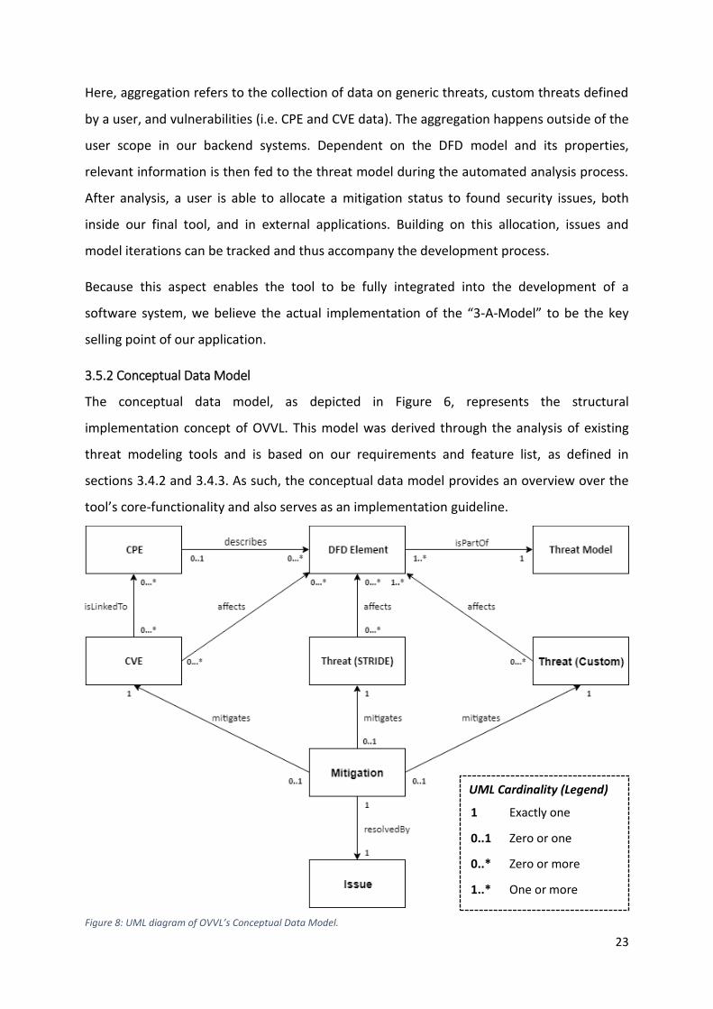
3.5.2 Conceptual Data Model
The conceptual data model, as depicted in Figure 6, represents the structural
implementation concept of OVVL. This model was derived through the analysis of existing
threat modeling tools and is based on our requirements and feature list, as defined in
sections 3.4.2 and 3.4.3. As such, the conceptual data model provides an overview over the
tool’s core-functionality and also serves as an implementation guideline.
Figure 8: UML diagram of OVVL’s Conceptual Data Model.
UML Cardinality (Legend)
1
0..1
0..*
1..*
Exactly one
Zero or one
Zero or more
One or more
24
DFD Element to Threat Model Relation
A DFD element can be either an interactor, process, data store or a data flow. A data flow
represents the communication flow between elements. It is used to link elements together,
so that not only the elements themselves, but also their interaction can be analyzed. These
connected elements form a representation of the software- and communication architecture
and thus the model for which a threat analysis can be made. To differentiate elements of the
same type during the threat analysis, each element defines multiple selectable sub-types,
e.g. “Browser Client”- and “Web Server”-Process. They can be distinguished further by
setting different properties, like “Isolation Level” and “Accepts User Input”3. A clear
distinction between elements not only of a different, but of the same type, is crucial for a
meaningful threat analysis and thus a useful threat model. Visually the elements can be
differentiated by their color and corresponding icons, an important aspect required to give a
clear overview over the software architecture we are trying to protect.
CPE to Element Relation
In order to ensure a thorough threat analysis, it is necessary to allow for the mapping of
certain software makes to the elements in the model. By searching for a certain software,
e.g. “Firefox 62.0.2”, the user is returned a list of matching CPE’s, which they then can link to
the element the search was requested from. By using CPE as an identifier, we make it
possible to specify which software an element in the model is based on in a standardized
manner. The resulting, more accurate element specification makes it possible to link known
software vulnerabilities to the model during the analysis process.
The underlying data is provided by the National Vulnerability Database (NVD) [20], a
database maintained by the National Institute of Standards and Technology (NIST) [33]. We
host an up-to-date copy in our own database. By using this data, our tool can not only
identify current software, but legacy software as well. We also implement a custom search
interface, which enables the process of searching CPE’s and linking them to the elements to
be significantly faster than NVDs official CPE search tool. This aspect is discussed further in
section 5.
3 Currently these properties and sub-types defined in OVVL are the same as in Microsoft’s TMT. In the future, we plan on defining new specifications.
25
CVE and Threats
In order to facilitate an extensive analysis, our tool differentiates between threats and
vulnerabilities. A threat is a possible risk of someone compromising and/or harming a
system, while a vulnerability can be exploited and thus may give rise to a threat [16, p.
1105]. The final tool will distinguish between CVE, STRIDE threats and Custom-Threats, all of
which are linked to their respective elements. For CVE-References being linked to the
elements, a CPE must first be set by the user.
STRIDE threats are threats found for a specific system, based on a fine-tuned STRIDE-Model
as explained in section 2.24. They are applied to the elements dynamically during the
analysis, depending on the element type, its connection and communication with other
elements and its properties. Since these threats, unlike the CVE-References, cannot be
ranked automatically, our tool will enable the user to prioritize the threats manually. While
STRIDE threats are not meant to demonstrate detailed threats a system faces, we consider it
a good approach for finding possible ways a system could be compromised.
Since each information system has different dependencies and possible threats, only having
predefined threats (STRIDE) and vulnerabilities (CVE) would not cover every risk a system
faces. By allowing for custom threats to be defined, new threats can be added to the
underlying analysis logic and are applied to each new system and analysis a user creates.
Our system looks for all type of threats and vulnerabilities, depending on the available data.
When combined, these threat types and vulnerabilities provide a wide overview over the
risks a system faces.
Mitigation and Issues
For our tool to be helpful not only for giving a threat-overview over a system, but also during
the development process, it is necessary for a user to be able to track and mitigate threats.
This use case is covered by the ability to prioritize found threats and setting their mitigation
status depending on whether the threat has been resolved or not. While it is not possible for
4 It is important to note that the threat definitions currently included in our tool are the same as in Microsoft’s
TMT. When continuing development past the MVP, we plan on setting our own threat definitions.
26
our tool to analyze the development status of a system, we want to make it possible to link
the mitigation status of threats to project tracking software like Jira [34] or FogBugz [35].
We plan on this being done by first having a mitigation list in our tool, from which a user
then can create issue-tickets in these project tracking tools. While the creation of tickets is
currently not implemented, the clear data structure within our current development status
allows this feature to be added without much effort.
3.5.3 Design
When looking at Microsoft’s TMT, we found its design and usability to be somewhat limited.
While serving its intended purpose, the general layout and behavior seemed dated and
unintuitive to us. Based on this observation, we consider a user friendly and appealing
design to be one of the main factors in making OVVL a competitive product.
Building a design guideline for OVVL was split into two parts. First, we analyzed Microsoft’s
TMT UX behavior (discussed in section 2.4.1) and derived UX requirements for our own tool
based on the results. These results then got incorporated in a general design guideline,
which was specified by the engineer within our team, who was responsible for the UX and
general design. The guideline includes screen mockups, UX behavior specification and font,
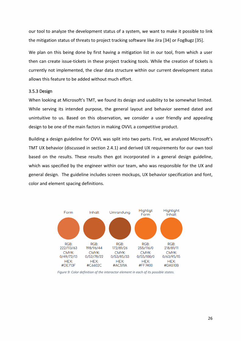
color and element spacing definitions.
Figure 9: Color definition of the interactor element in each of its possible states.
27
In summary, the resulting guideline defines OVVL’s design the following way:
1. Separation of concern through the splitting of the view into a design and an analysis
view.
2. At any point during the threat modeling process, only information relevant for that
point is displayed.
3. A dark gray theme throughout the application, with only elements being colored.
4. A drag and drop system to place elements.
5. Highlighting of elements currently interacted with by the user.
The full design guideline can be found in Appendix A.
3.6 Implementation
Even though the scope of the project, as discussed in section 3.1, is split into two sections,
“MVP” and “Full Product”, it is important to note that these parts, while separate, are not
isolated from each other. Instead, they are connected by a core implementation structure
spanning the whole project. This allows the full product to be built upon the foundation laid
out by the MVP, and not having to start developing it from scratch. The core implementation
structure in our case means:
• We use the same technology stack for the MVP and for the full product.
• Features are implemented according to their priority within our project, as discussed
in section 3.4.3.
• Features are implemented following the modular approach laid out by the
conceptual data model in section 3.5.2, so new features can be integrated into the
tool without changing its core structure.
• In order to include them in the actual product, features added during MVP
development were implemented rudimentary, though still in a proper and functional
manner.
• We focus on clean code, to make it easier to keep an overview over the project’s
logic while its complexity increases.
28
3.6.1 Technology Stack
Three factors were kept in mind while choosing the technology stack of OVVL: Scalability,
support availability, and complexity. The chosen technologies as a whole must be scalable,
so our tool can be used by a large number of users. No technology should constitute a
bottleneck, limiting the performance of other parts of the application. Support availability is
an important factor, since issues arising during development need to be resolved in a timely
manner. Combined with the scalability factor, we concluded, that each technology must be
established enough to have a large user base, but still modern enough to guarantee a
reasonable performance. Each technology also must be complex enough to cover the wide
range of development use cases the implementation of our tool requires. This includes the
communication between front- and backend, state management, and general
interconnectivity between the individual parts of our application. Also, the technologies
must be complex enough to guarantee scalability, but still be straightforward enough to
allow for fast paced development.
3.6.1.1 Frontend
Angular
Angular is an open-source web application framework [36], with its development being led
by the Google Angular team [37]. It enables the development of client-sided web
applications based on HTML, CSS, and the programming language TypeScript [38]. While
standard CSS is the default styling language in Angular applications [39], we use SCSS to
structure styling rules more clearly. TypeScript is a superset of JavaScript, utilizing the same
syntax and semantics as JavaScript [40]. TypeScript facilitates optional type checking for a
clearer code structure, which is crucial in large-scale applications like OVVL. Still, most
external JavaScript libraries can be integrated into an Angular application as well.
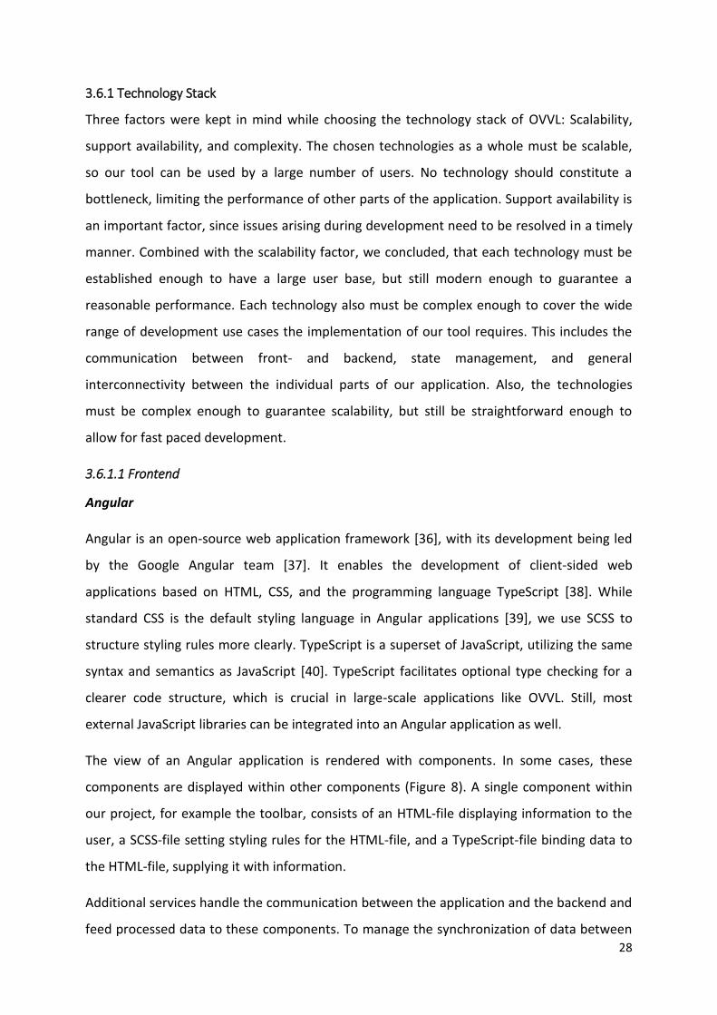
The view of an Angular application is rendered with components. In some cases, these
components are displayed within other components (Figure 8). A single component within
our project, for example the toolbar, consists of an HTML-file displaying information to the
user, a SCSS-file setting styling rules for the HTML-file, and a TypeScript-file binding data to
the HTML-file, supplying it with information.
Additional services handle the communication between the application and the backend and
feed processed data to these components. To manage the synchronization of data between
29
components, we additionally integrate the Redux state management engine [41]. This is
discussed further in section 3.6.5.
Angular’s component-based approach offers the possibility to dynamically render certain
aspects of an application depending on the underlying data. By processing most of the data
in background services, the view stays mostly unaffected should intense calculations take
place, e.g. during the analysis process in OVVL. This aspect is crucial for the scalability of our
application. Additionally, the ability to integrate external JavaScript frameworks into the
application and the type safety offered by TypeScript, made Angular the right choice for our
project.
3.6.1.2 Backend
Spring Boot
We utilize a Spring boot backend in our project, which handles most of the data processing.
This includes a large part of the threat modeling and threat analysis. By keeping most of the
calculation load away from the frontend, we increase the performance of the Angular
application and thus improve the user experience.
Spring is a Java-based, open-source framework providing the infrastructure needed to create
large-scale applications [42]. While Spring already offers an extensive foundation for the
creation of a structured backend application, its extensive manual configuration options can
Figure 10: Abstracted component structure of our Angular application.
30
make it difficult to set up. Spring boot solves this issue by building on top of the Spring
framework [43] and following the “convention over configuration” design paradigm [44]. In
this case, Spring boot decreases the configuration time and boilerplate code immensely, by
auto-configuring the core application and its dependencies. Additionally, a Spring boot
application can be used as standalone – by default, a Spring boot application is deployed on
its embedded Tomcat container, instead of a separate webserver.
Swagger
Swagger is a specification tool which can be integrated into a Spring boot application [45]. It
is used to document and to generate REST web services by describing API endpoints [45]. Put
more generally, Swagger defines the endpoints of a Spring boot backend, which can be
addressed by the frontend application for communication purposes. The structure of the
transferred data, HTTP method to be used, and URL address can all be manually defined in
Swagger. Transferred data is then processed by the respective endpoint methods within the
Spring boot backend. After processing, a response – which type and content is also defined
in Swagger – is sent back to the frontend.
In our case, our API is defined by several URL endpoints. By naming these endpoints similar
to the task that needs processing, we not only ensure a clear documentation, but also
decrease the amount of communication errors between front- and backend.
Swagger’s automatic and specific endpoint generation and clear documentation structure
make it a helpful tool within our project. It significantly improves the quality of our backend
as well as the development speed.
MongoDB
MongoDB is an open-source document-oriented database [46]. Unlike a relational database,
MongoDB stores data object as separate documents [47]. MongoDB focuses on high-
performance, availability and scalability [47], which makes it ideal for our project.
In OVVL, we differentiate between five types of data which need to be stored: Threats,
vulnerabilities (CVE), software makes (CPE), threat models, and user data. While the storage
of the other types could be managed in a relation database, the big data set consisting of
CVE- and CPE-References can be handled faster by MongoDB. This increase in performance
31
compared to existing solutions, like the official NVD [48], is of significant value. This aspect is
discussed further in section 5.
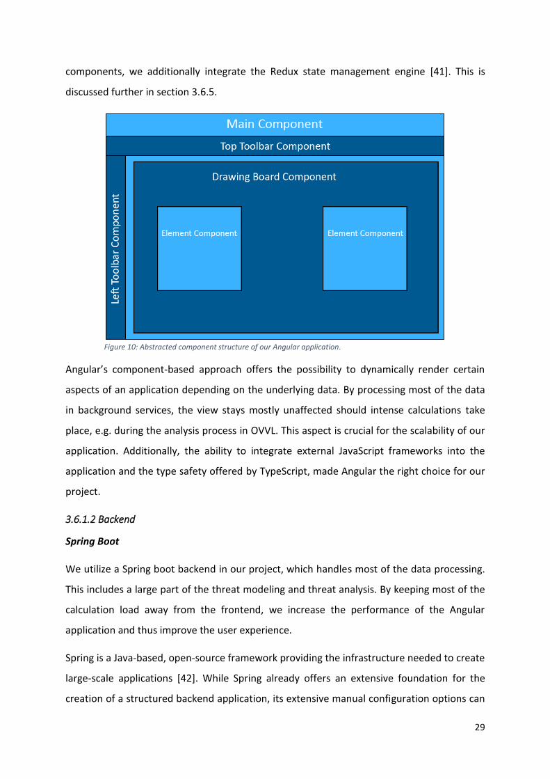
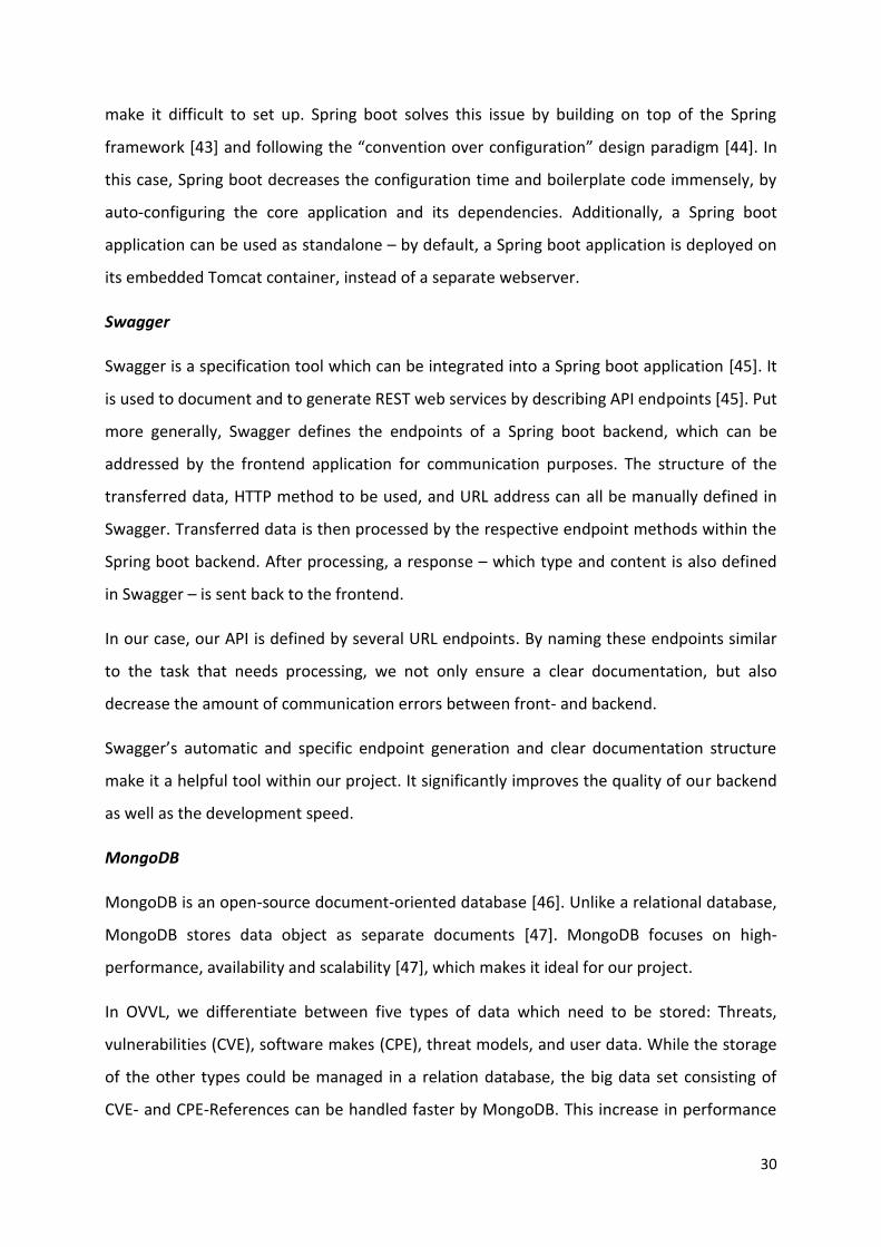
3.6.2 Deployment Architecture
The architecture of our deployed system is shown in Figure 10. The communication between
all entities in the system is HTTP based [49], utilizing the JSON file format [50].
In the MVP, the data the Angular application sends to the
backend mostly consists of DFD data (e.g. to start analysis),
or simple input data which needs additional processing (e.g.
CPE selection). To access processed data, the Angular
application sends a request to the respective endpoints in
the backend. Returned data consists, amongst other things,
of found threats or CVE-References, additional specification
data like CPE, authorization data, or model data when
loading a saved DFD.
Storing data is handled by the Spring boot backend. Data
which needs to be persisted, like DFDs during the analysis
process, gets saved in a MongoDB. Similarly, data needed
by the backend for processing (e.g. CVE-References and
threats), or data requested by the user (e.g. CPEs), is loaded
from the MongoDB to the Spring boot backend.
3.6.3 Class Structure and Data Transfer
The class structure, though fundamentally the same, differs in its implementation between
front- and backend. This is done to minimize the amount of data, which is passed during the
communication between the two sub-systems. At any point during the communication
process, only relevant data is included in the JSON object – for example, when analyzing a
threat model, coordinates are not considered relevant and do not have to be included in the
data sent to the backend. To showcase this, the differences and changes in the class
structure during each step in the threat analysis process are described in the following
paragraphs.
MongoDB
Database
DFD data Input
Angular
Application
Swagger
API
Spring boot
Application
DFD data
Threat & CVE data CPEs
DFD data Threat & CVE data CPEs
Figure 11: OVVL deployment architecture.
32
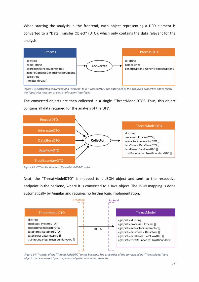
When starting the analysis in the frontend, each object representing a DFD element is
converted to a “Data Transfer Object” (DTO), which only contains the data relevant for the
analysis.
The converted objects are then collected in a single “ThreatModelDTO”. Thus, this object
contains all data required for the analysis of the DFD.
Next, the “ThreatModelDTO” is mapped to a JSON object and sent to the respective
endpoint in the backend, where it is converted to a Java object. The JSON mapping is done
automatically by Angular and requires no further logic implementation.
Process ProcessDTO
id: string
name: string
coordinates: PointCoordinates
genericOptions: GenericProcessOptions
cpe: string
threats: Threat []
id: string
name: string
genericOptions: GenericProcessOptions
Converter
Figure 12: Abstracted conversion of a "Process" to a "ProcessDTO". The datatypes of the displayed properties either follow the TypeScript notation or consist of custom interfaces.
ThreatModelDTO
TrustBoundaryDTO
DataFlowDTO
DataStoreDTO
InteractorDTO
ProcessDTO
id: string
processes: ProcessDTO []
interactors: InteractorDTO []
dataStores: DataStoreDTO []
dataFlows: DataFlowDTO []
trustBoundaries: TrustBoundaryDTO []
Collector
Figure 13: DTO collection in a "ThreatModelDTO" object.
«get/set» id: string
«get/set» processes: Process []
«get/set» interactors: Interactor []
«get/set» dataStores: DataStore []
«get/set» dataFlows: DataFlowDTO []
«get/set» trustBoundaries: TrustBoundary []
id: string
processes: ProcessDTO []
interactors: InteractorDTO []
dataStores: DataStoreDTO []
dataFlows: DataFlowDTO []
trustBoundaries: TrustBoundaryDTO []
ThreatModelDTO ThreatModel
HTTPS
Backend Frontend
Figure 14: Transfer of the "ThreatModelDTO" to the backend. The properties of the corresponding “ThreatModel” Java object can be accessed by auto-generated getter and setter methods.
33
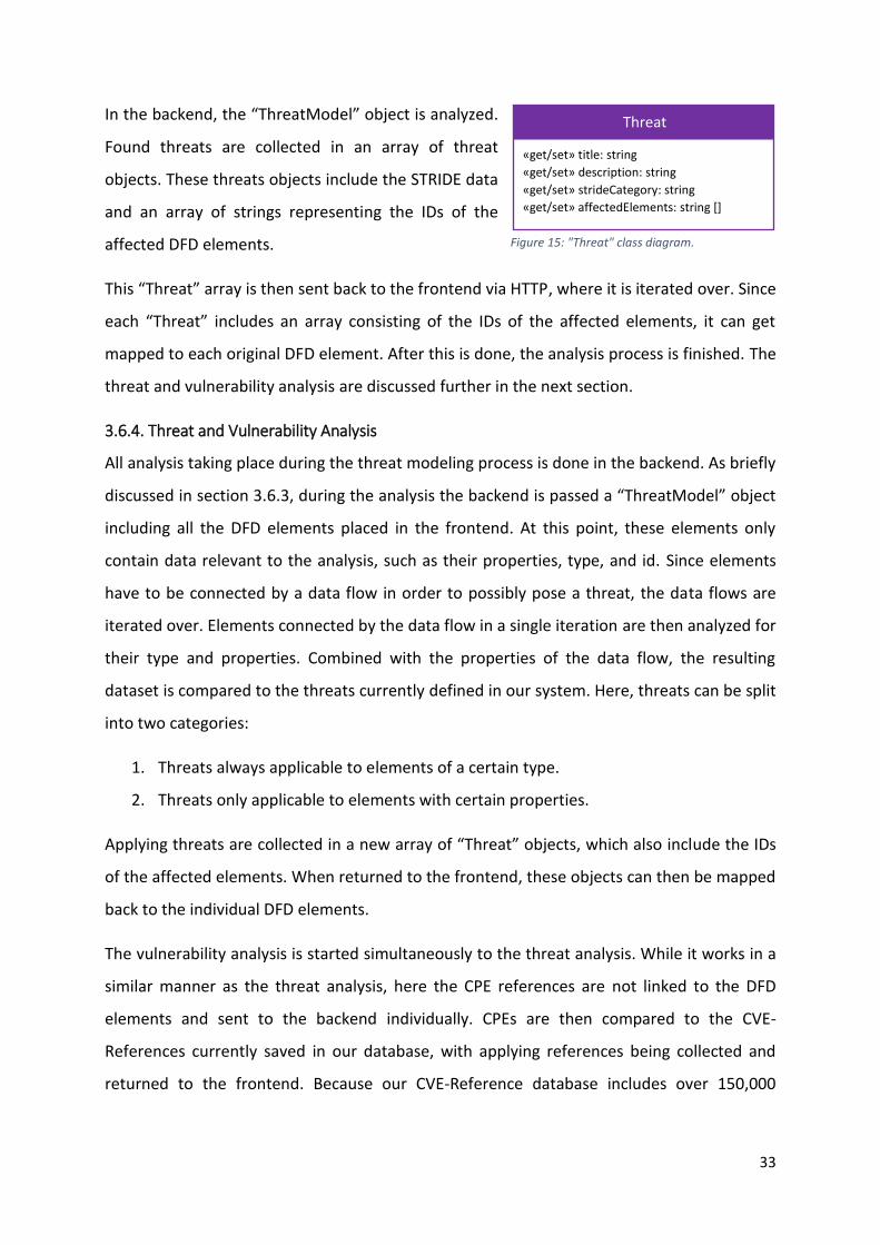
In the backend, the “ThreatModel” object is analyzed.
Found threats are collected in an array of threat
objects. These threats objects include the STRIDE data
and an array of strings representing the IDs of the
affected DFD elements.
This “Threat” array is then sent back to the frontend via HTTP, where it is iterated over. Since
each “Threat” includes an array consisting of the IDs of the affected elements, it can get
mapped to each original DFD element. After this is done, the analysis process is finished. The
threat and vulnerability analysis are discussed further in the next section.
3.6.4. Threat and Vulnerability Analysis
All analysis taking place during the threat modeling process is done in the backend. As briefly
discussed in section 3.6.3, during the analysis the backend is passed a “ThreatModel” object
including all the DFD elements placed in the frontend. At this point, these elements only
contain data relevant to the analysis, such as their properties, type, and id. Since elements
have to be connected by a data flow in order to possibly pose a threat, the data flows are
iterated over. Elements connected by the data flow in a single iteration are then analyzed for
their type and properties. Combined with the properties of the data flow, the resulting
dataset is compared to the threats currently defined in our system. Here, threats can be split
into two categories:
1. Threats always applicable to elements of a certain type.
2. Threats only applicable to elements with certain properties.
Applying threats are collected in a new array of “Threat” objects, which also include the IDs
of the affected elements. When returned to the frontend, these objects can then be mapped
back to the individual DFD elements.
The vulnerability analysis is started simultaneously to the threat analysis. While it works in a
similar manner as the threat analysis, here the CPE references are not linked to the DFD
elements and sent to the backend individually. CPEs are then compared to the CVE-
References currently saved in our database, with applying references being collected and
returned to the frontend. Because our CVE-Reference database includes over 150,000
Threat
«get/set» title: string
«get/set» description: string
«get/set» strideCategory: string
«get/set» affectedElements: string []
Figure 15: "Threat" class diagram.
34
datasets, returned references are displayed immediately to minimize loading times. For the
same reason, threat analysis is done separately from the vulnerability analysis.
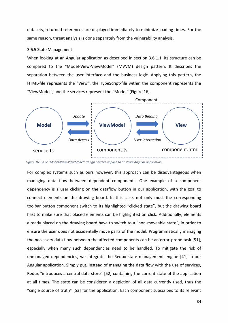
3.6.5 State Management
When looking at an Angular application as described in section 3.6.1.1, its structure can be
compared to the “Model-View-ViewModel” (MVVM) design pattern. It describes the
separation between the user interface and the business logic. Applying this pattern, the
HTML-file represents the “View”, the TypeScript-file within the component represents the
“ViewModel”, and the services represent the “Model” (Figure 16).
For complex systems such as ours however, this approach can be disadvantageous when
managing data flow between dependent components. One example of a component
dependency is a user clicking on the dataflow button in our application, with the goal to
connect elements on the drawing board. In this case, not only must the corresponding
toolbar button component switch to its highlighted “clicked state”, but the drawing board
hast to make sure that placed elements can be highlighted on click. Additionally, elements
already placed on the drawing board have to switch to a “non-moveable state”, in order to
ensure the user does not accidentally move parts of the model. Programmatically managing
the necessary data flow between the affected components can be an error-prone task [51],
especially when many such dependencies need to be handled. To mitigate the risk of
unmanaged dependencies, we integrate the Redux state management engine [41] in our
Angular application. Simply put, instead of managing the data flow with the use of services,
Redux “introduces a central data store” [52] containing the current state of the application
at all times. The state can be considered a depiction of all data currently used, thus the
“single source of truth” [53] for the application. Each component subscribes to its relevant
ViewModel View Model
Component
component.html component.ts service.ts
Data Binding
User Interaction Data Access
Update
Figure 16: Basic "Model-View-ViewModel“ design pattern applied to abstract Angular application.
35
sub-parts of the state and gets the updated data automatically when that section of the
state gets updated. When data within a single component changes, e.g. trough user input,
this component updates the corresponding part of the state – and thus updates all
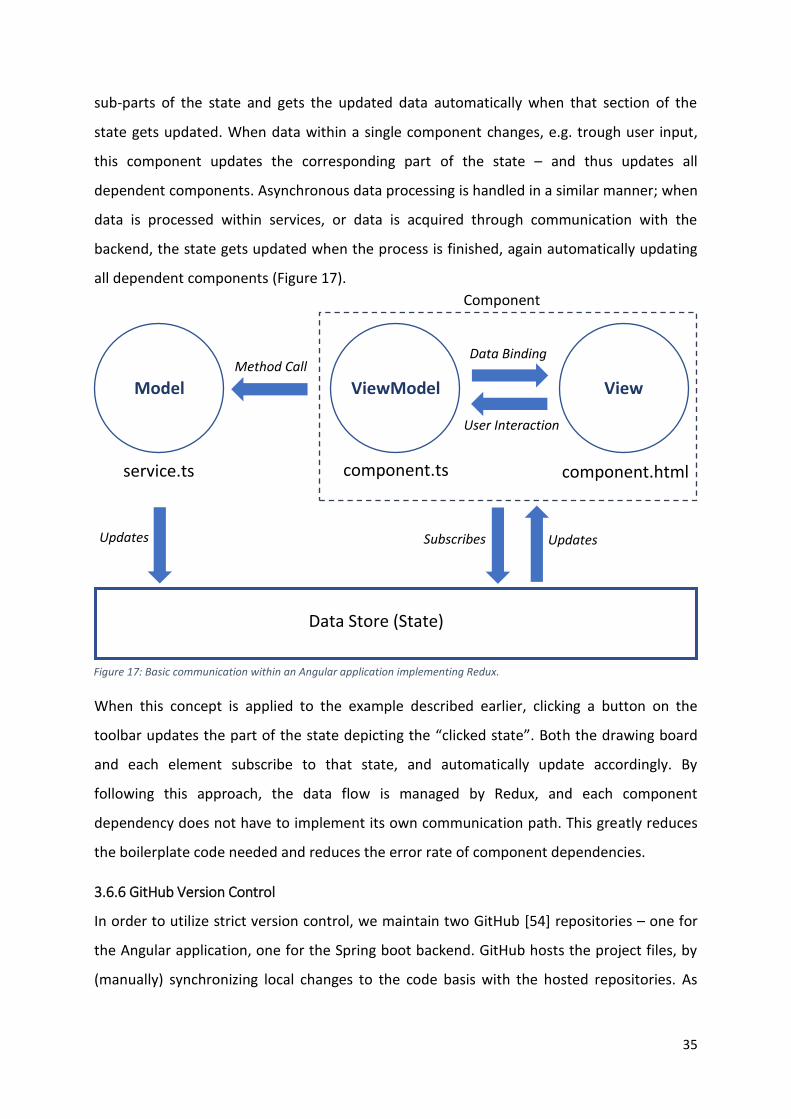
dependent components. Asynchronous data processing is handled in a similar manner; when
data is processed within services, or data is acquired through communication with the
backend, the state gets updated when the process is finished, again automatically updating
all dependent components (Figure 17).
When this concept is applied to the example described earlier, clicking a button on the
toolbar updates the part of the state depicting the “clicked state”. Both the drawing board
and each element subscribe to that state, and automatically update accordingly. By
following this approach, the data flow is managed by Redux, and each component
dependency does not have to implement its own communication path. This greatly reduces
the boilerplate code needed and reduces the error rate of component dependencies.
3.6.6 GitHub Version Control
In order to utilize strict version control, we maintain two GitHub [54] repositories – one for
the Angular application, one for the Spring boot backend. GitHub hosts the project files, by
(manually) synchronizing local changes to the code basis with the hosted repositories. As
Figure 17: Basic communication within an Angular application implementing Redux.
Component
ViewModel View
component.html
Data Binding
User Interaction
component.ts service.ts
Model Method Call
Updates Updates Subscribes
Data Store (State)
36
such, the online repositories represent the current development state of our project.
Following benefits come with the utilization of GitHub as version control system:
• Documentation. In the online repositories, the project and its dependencies can be
described.
• Backup. Because project files are available locally as well as stored online, the risk of
losing important work is mitigated.
• Tracking of changes. Especially when multiple people are collaborating on a single
code base, keeping track of project iterations and changes within them is of great
help.
• Integration. GitHub repositories can be integrated into many cloud based hosting
platforms, such as Heroku [55]. This is discussed further in section 3.6.7.
Figure 18: OVVL web application GitHub [53] repository.
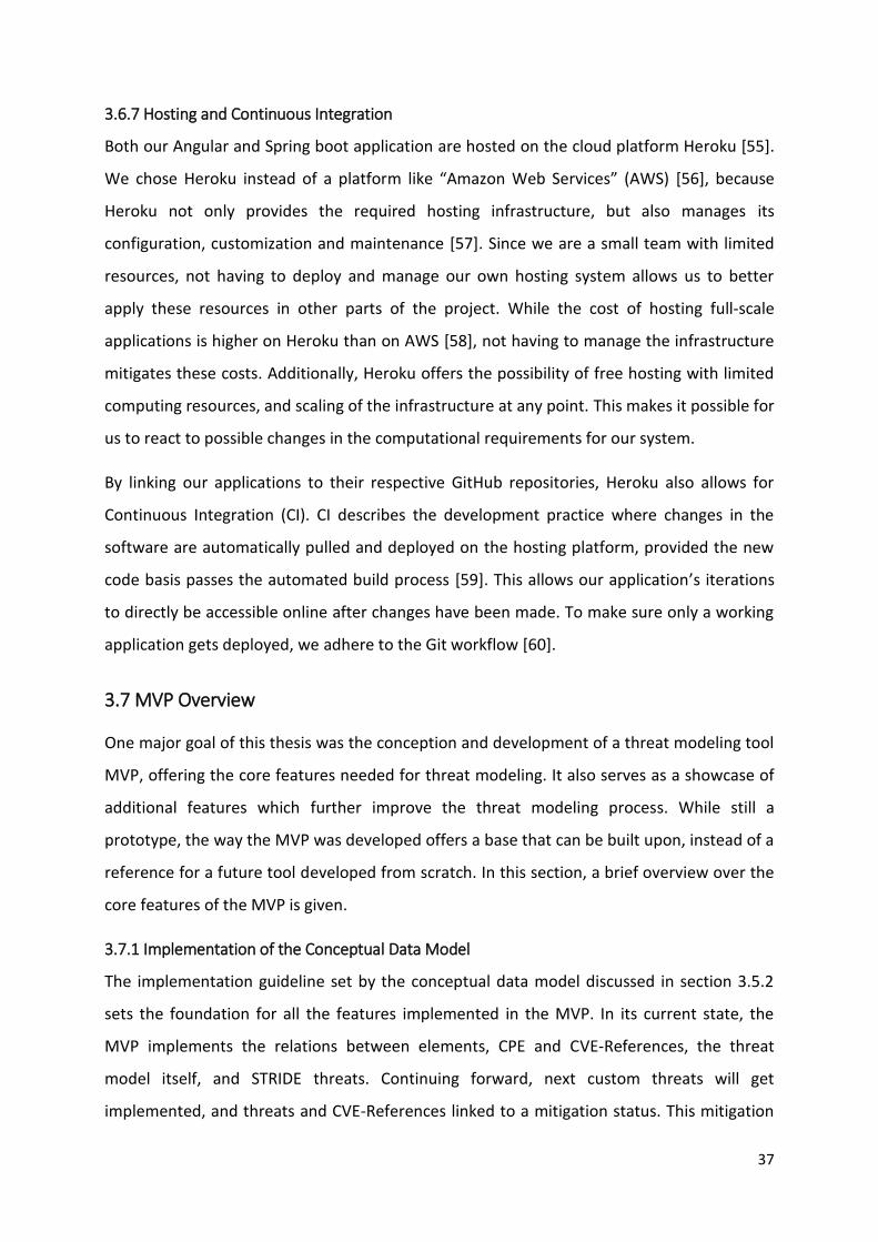
37
3.6.7 Hosting and Continuous Integration
Both our Angular and Spring boot application are hosted on the cloud platform Heroku [55].
We chose Heroku instead of a platform like “Amazon Web Services” (AWS) [56], because
Heroku not only provides the required hosting infrastructure, but also manages its
configuration, customization and maintenance [57]. Since we are a small team with limited
resources, not having to deploy and manage our own hosting system allows us to better
apply these resources in other parts of the project. While the cost of hosting full-scale
applications is higher on Heroku than on AWS [58], not having to manage the infrastructure
mitigates these costs. Additionally, Heroku offers the possibility of free hosting with limited
computing resources, and scaling of the infrastructure at any point. This makes it possible for
us to react to possible changes in the computational requirements for our system.
By linking our applications to their respective GitHub repositories, Heroku also allows for
Continuous Integration (CI). CI describes the development practice where changes in the
software are automatically pulled and deployed on the hosting platform, provided the new
code basis passes the automated build process [59]. This allows our application’s iterations
to directly be accessible online after changes have been made. To make sure only a working
application gets deployed, we adhere to the Git workflow [60].
3.7 MVP Overview
One major goal of this thesis was the conception and development of a threat modeling tool
MVP, offering the core features needed for threat modeling. It also serves as a showcase of
additional features which further improve the threat modeling process. While still a
prototype, the way the MVP was developed offers a base that can be built upon, instead of a
reference for a future tool developed from scratch. In this section, a brief overview over the
core features of the MVP is given.
3.7.1 Implementation of the Conceptual Data Model
The implementation guideline set by the conceptual data model discussed in section 3.5.2
sets the foundation for all the features implemented in the MVP. In its current state, the
MVP implements the relations between elements, CPE and CVE-References, the threat
model itself, and STRIDE threats. Continuing forward, next custom threats will get
implemented, and threats and CVE-References linked to a mitigation status. This mitigation
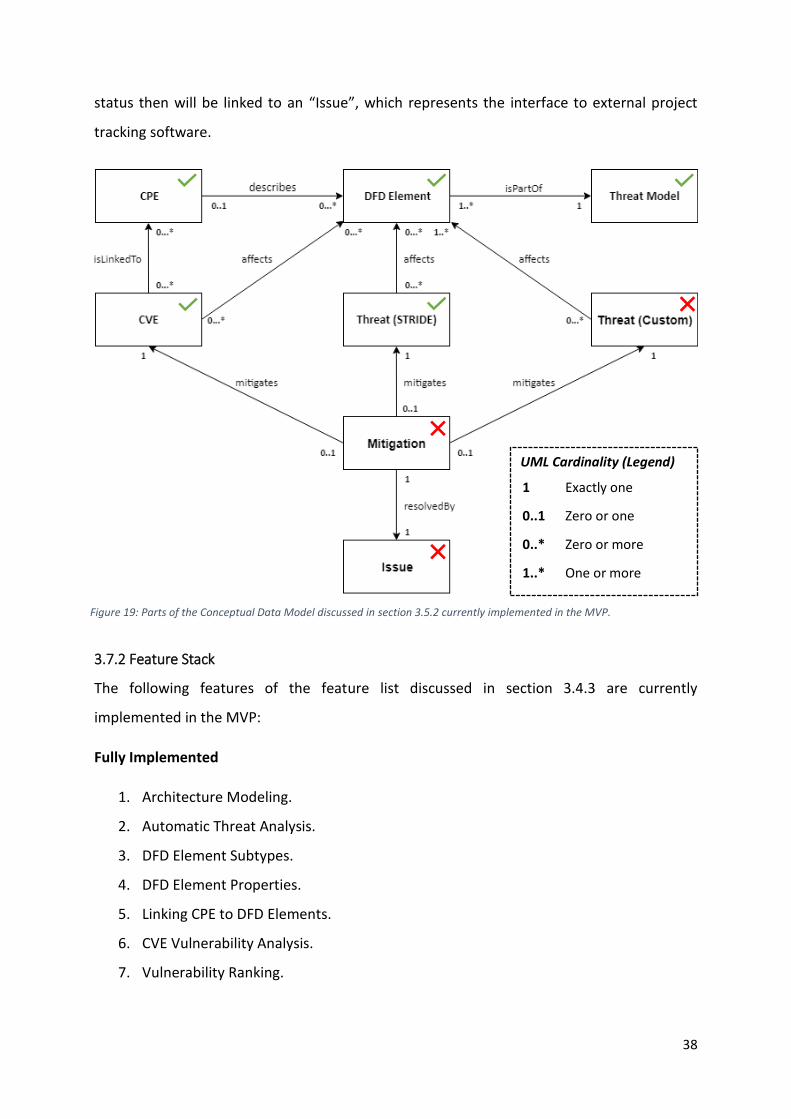
38
status then will be linked to an “Issue”, which represents the interface to external project
tracking software.
3.7.2 Feature Stack
The following features of the feature list discussed in section 3.4.3 are currently
implemented in the MVP:
Fully Implemented
1. Architecture Modeling.
2. Automatic Threat Analysis.
3. DFD Element Subtypes.
4. DFD Element Properties.
5. Linking CPE to DFD Elements.
6. CVE Vulnerability Analysis.
7. Vulnerability Ranking.
Figure 19: Parts of the Conceptual Data Model discussed in section 3.5.2 currently implemented in the MVP.
UML Cardinality (Legend)
1
0..1
0..*
1..*
Exactly one
Zero or one
Zero or more
One or more
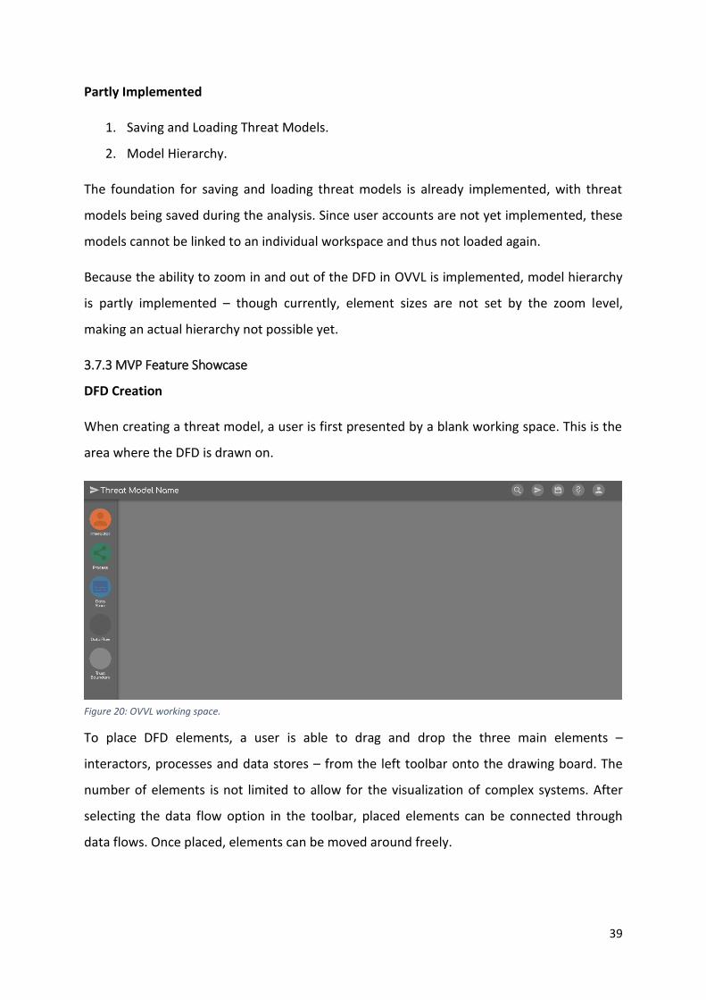
39
Partly Implemented
1. Saving and Loading Threat Models.
2. Model Hierarchy.
The foundation for saving and loading threat models is already implemented, with threat
models being saved during the analysis. Since user accounts are not yet implemented, these
models cannot be linked to an individual workspace and thus not loaded again.
Because the ability to zoom in and out of the DFD in OVVL is implemented, model hierarchy
is partly implemented – though currently, element sizes are not set by the zoom level,
making an actual hierarchy not possible yet.
3.7.3 MVP Feature Showcase
DFD Creation
When creating a threat model, a user is first presented by a blank working space. This is the
area where the DFD is drawn on.
To place DFD elements, a user is able to drag and drop the three main elements –
interactors, processes and data stores – from the left toolbar onto the drawing board. The
number of elements is not limited to allow for the visualization of complex systems. After
selecting the data flow option in the toolbar, placed elements can be connected through
data flows. Once placed, elements can be moved around freely.
Figure 20: OVVL working space.
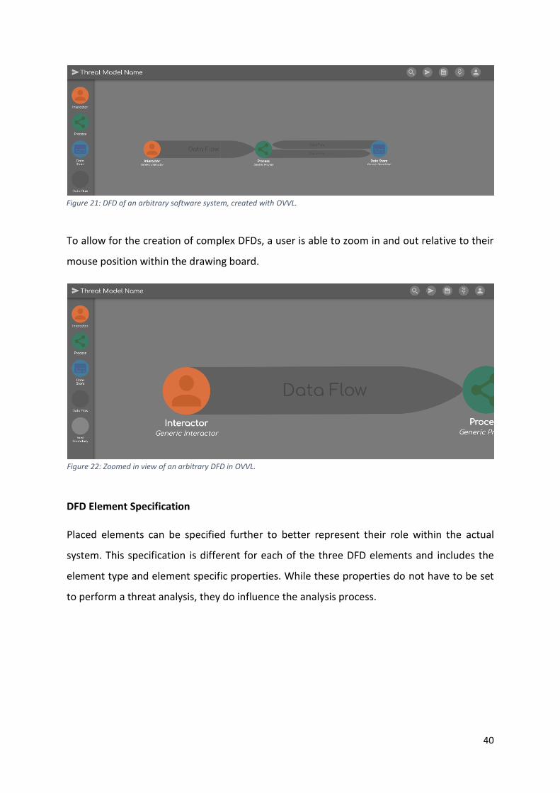
40
To allow for the creation of complex DFDs, a user is able to zoom in and out relative to their
mouse position within the drawing board.
DFD Element Specification
Placed elements can be specified further to better represent their role within the actual
system. This specification is different for each of the three DFD elements and includes the
element type and element specific properties. While these properties do not have to be set
to perform a threat analysis, they do influence the analysis process.
Figure 21: DFD of an arbitrary software system, created with OVVL.
Figure 22: Zoomed in view of an arbitrary DFD in OVVL.
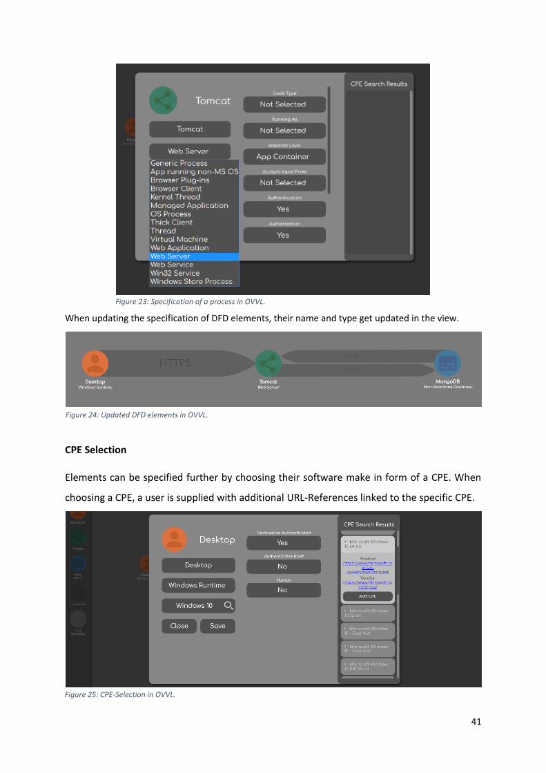
41
When updating the specification of DFD elements, their name and type get updated in the view.
CPE Selection
Elements can be specified further by choosing their software make in form of a CPE. When
choosing a CPE, a user is supplied with additional URL-References linked to the specific CPE.
Figure 25: CPE-Selection in OVVL.
Figure 24: Updated DFD elements in OVVL.
Figure 23: Specification of a process in OVVL.
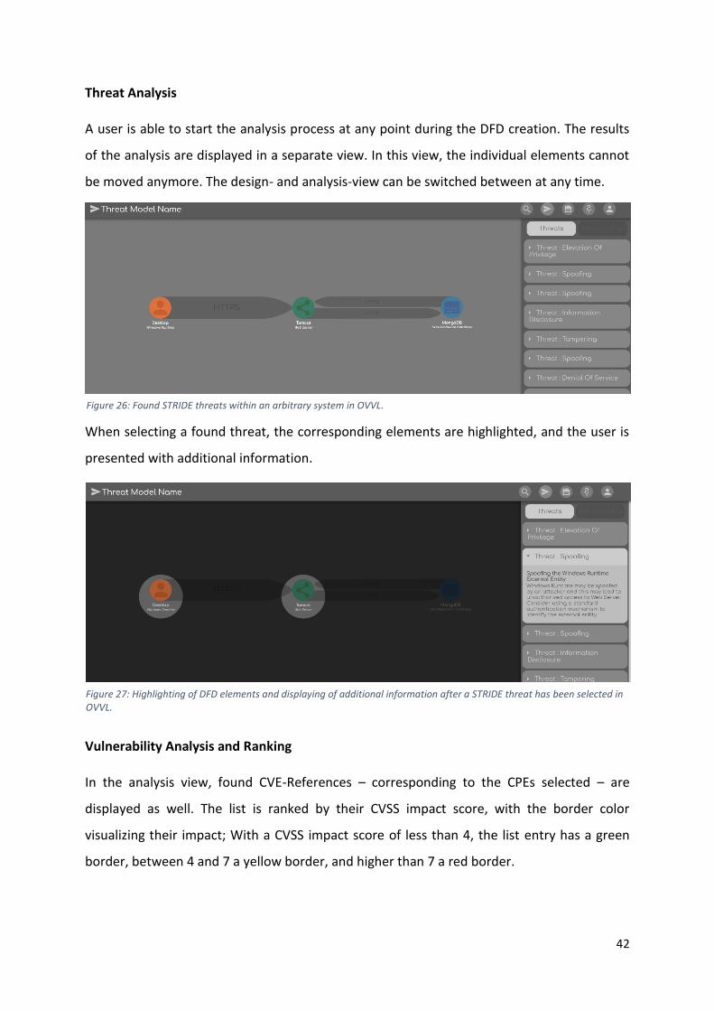
42
Threat Analysis
A user is able to start the analysis process at any point during the DFD creation. The results
of the analysis are displayed in a separate view. In this view, the individual elements cannot
be moved anymore. The design- and analysis-view can be switched between at any time.
When selecting a found threat, the corresponding elements are highlighted, and the user is
presented with additional information.
Vulnerability Analysis and Ranking
In the analysis view, found CVE-References – corresponding to the CPEs selected – are
displayed as well. The list is ranked by their CVSS impact score, with the border color
visualizing their impact; With a CVSS impact score of less than 4, the list entry has a green
border, between 4 and 7 a yellow border, and higher than 7 a red border.
Figure 26: Found STRIDE threats within an arbitrary system in OVVL.
Figure 27: Highlighting of DFD elements and displaying of additional information after a STRIDE threat has been selected in OVVL.
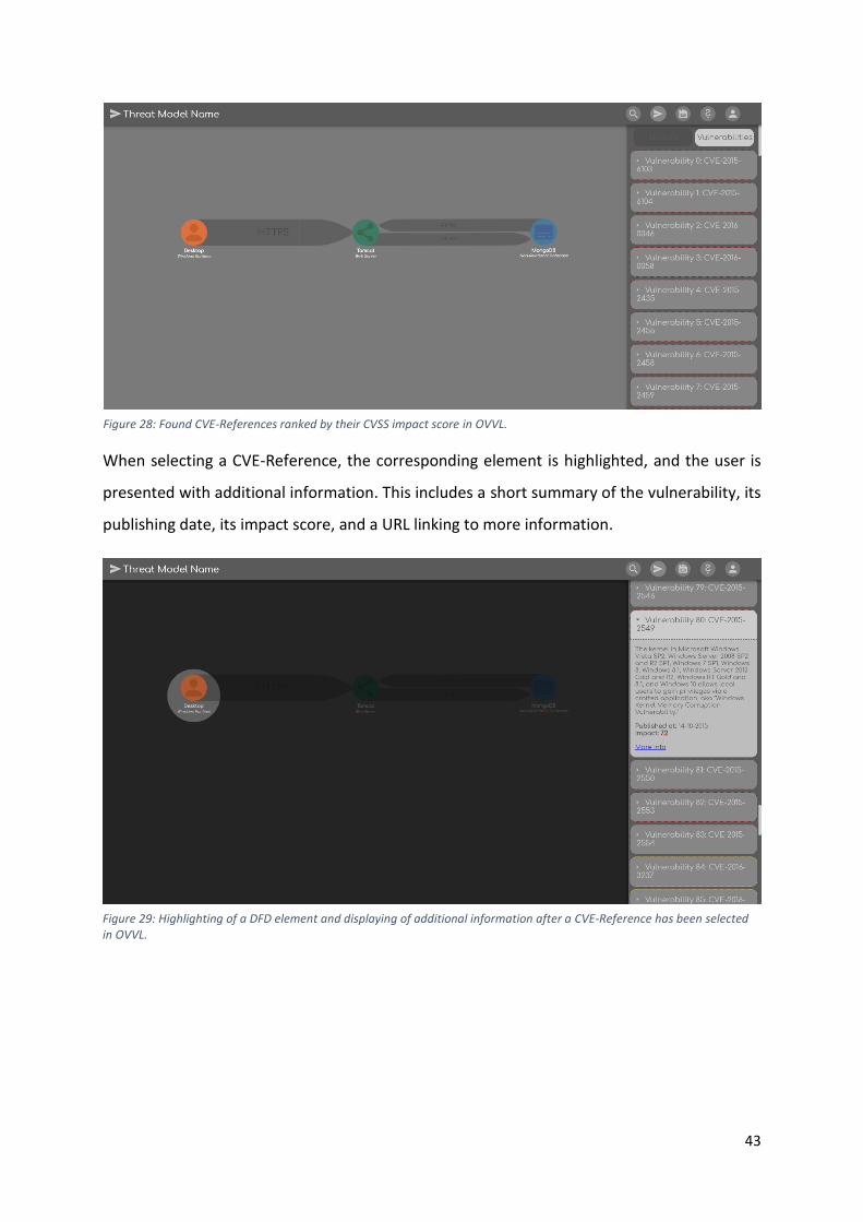
43
When selecting a CVE-Reference, the corresponding element is highlighted, and the user is
presented with additional information. This includes a short summary of the vulnerability, its
publishing date, its impact score, and a URL linking to more information.
Figure 29: Highlighting of a DFD element and displaying of additional information after a CVE-Reference has been selected in OVVL.
Figure 28: Found CVE-References ranked by their CVSS impact score in OVVL.
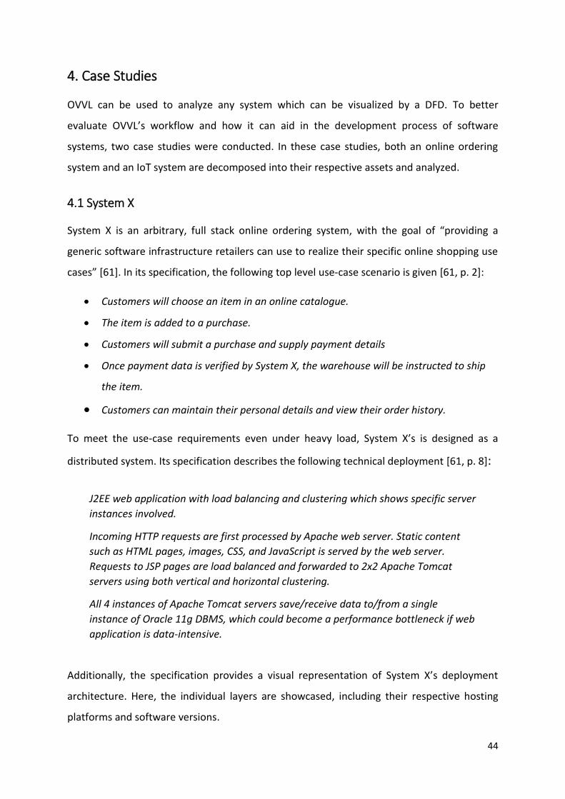
44
4. Case Studies
OVVL can be used to analyze any system which can be visualized by a DFD. To better
evaluate OVVL’s workflow and how it can aid in the development process of software
systems, two case studies were conducted. In these case studies, both an online ordering
system and an IoT system are decomposed into their respective assets and analyzed.
4.1 System X
System X is an arbitrary, full stack online ordering system, with the goal of “providing a
generic software infrastructure retailers can use to realize their specific online shopping use
cases” [61]. In its specification, the following top level use-case scenario is given [61, p. 2]:
• Customers will choose an item in an online catalogue.
• The item is added to a purchase.
• Customers will submit a purchase and supply payment details
• Once payment data is verified by System X, the warehouse will be instructed to ship
the item.
• Customers can maintain their personal details and view their order history.
To meet the use-case requirements even under heavy load, System X’s is designed as a
distributed system. Its specification describes the following technical deployment [61, p. 8]:
Additionally, the specification provides a visual representation of System X’s deployment
architecture. Here, the individual layers are showcased, including their respective hosting
platforms and software versions.
J2EE web application with load balancing and clustering which shows specific server
instances involved.
Incoming HTTP requests are first processed by Apache web server. Static content
such as HTML pages, images, CSS, and JavaScript is served by the web server.
Requests to JSP pages are load balanced and forwarded to 2x2 Apache Tomcat
servers using both vertical and horizontal clustering.
All 4 instances of Apache Tomcat servers save/receive data to/from a single
instance of Oracle 11g DBMS, which could become a performance bottleneck if web
application is data-intensive.
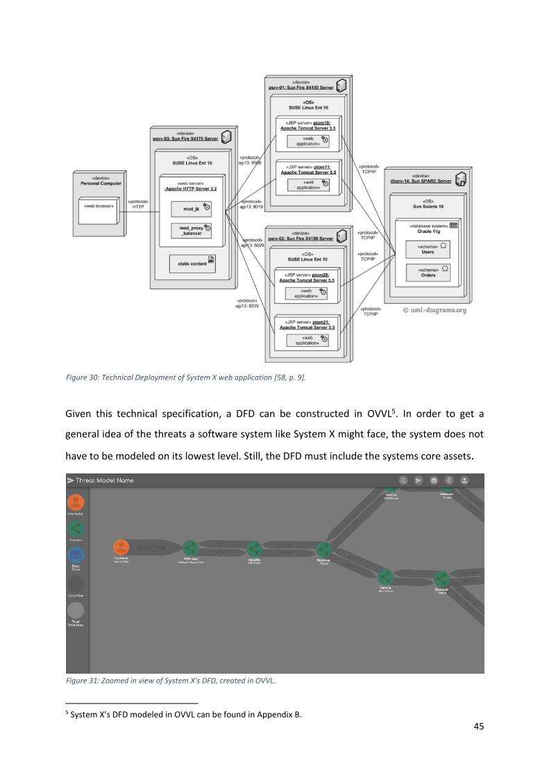
45
Given this technical specification, a DFD can be constructed in OVVL5. In order to get a
general idea of the threats a software system like System X might face, the system does not
have to be modeled on its lowest level. Still, the DFD must include the systems core assets.
5 System X’s DFD modeled in OVVL can be found in Appendix B.
Figure 30: Technical Deployment of System X web application [58, p. 9].
Figure 31: Zoomed in view of System X's DFD, created in OVVL.
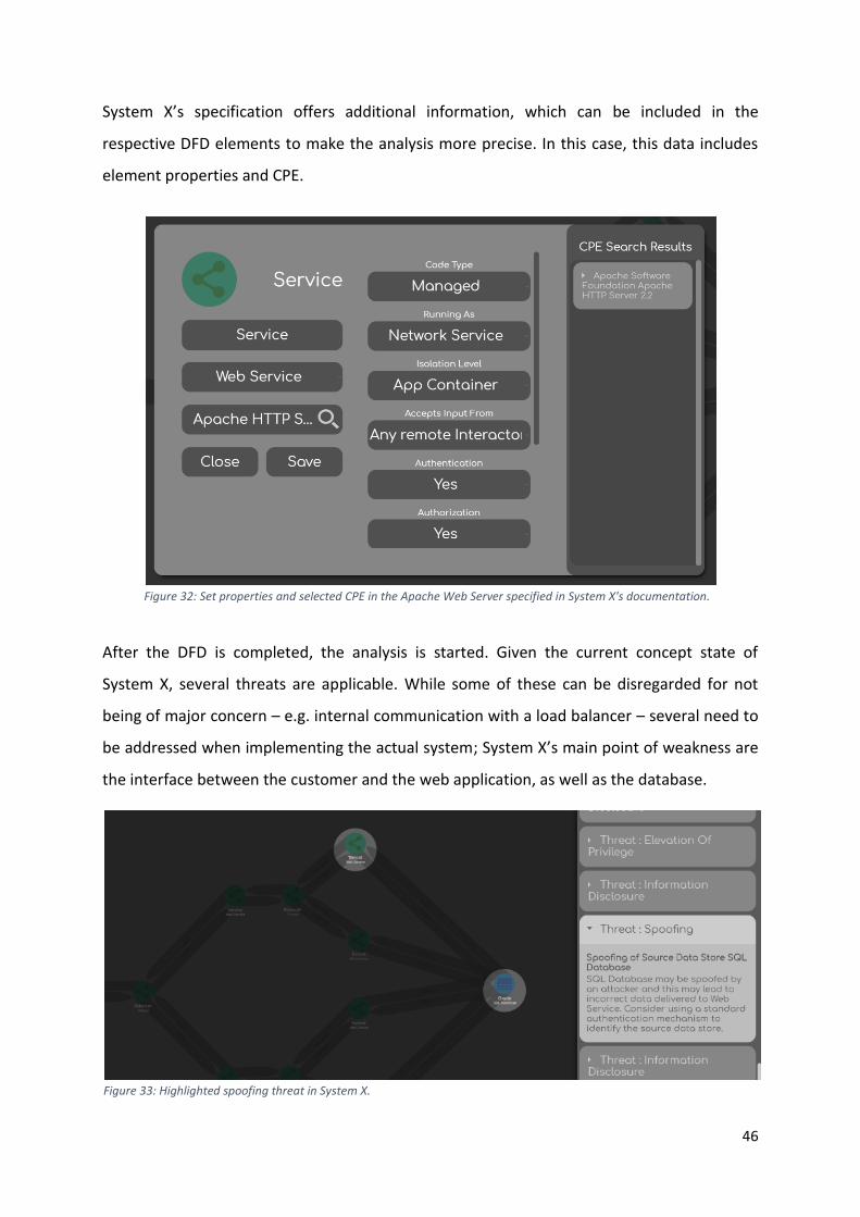
46
System X’s specification offers additional information, which can be included in the
respective DFD elements to make the analysis more precise. In this case, this data includes
element properties and CPE.
After the DFD is completed, the analysis is started. Given the current concept state of
System X, several threats are applicable. While some of these can be disregarded for not
being of major concern – e.g. internal communication with a load balancer – several need to
be addressed when implementing the actual system; System X’s main point of weakness are
the interface between the customer and the web application, as well as the database.
Figure 32: Set properties and selected CPE in the Apache Web Server specified in System X's documentation.
Figure 33: Highlighted spoofing threat in System X.
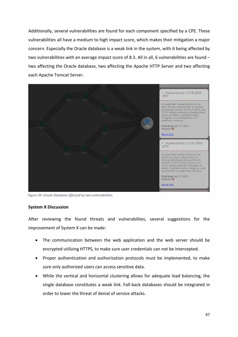
47
Additionally, several vulnerabilities are found for each component specified by a CPE. These
vulnerabilities all have a medium to high impact score, which makes their mitigation a major
concern. Especially the Oracle database is a weak link in the system, with it being affected by
two vulnerabilities with an average impact score of 8.3. All in all, 6 vulnerabilities are found –
two affecting the Oracle database, two affecting the Apache HTTP Server and two affecting
each Apache Tomcat Server.
System X Discussion
After reviewing the found threats and vulnerabilites, several suggestions for the
improvement of System X can be made:
• The communication between the web application and the web server should be
encrypted utilizing HTTPS, to make sure user credentials can not be intercepted.
• Proper authentication and authorization protocols must be implemented, to make
sure only authorized users can access sensitive data.
• While the vertical and horizontal clustering allows for adequate load balancing, the
single database constitutes a weak link. Fall-back databases should be integrated in
order to lower the threat of denial of service attacks.
Figure 34: Oracle Database affected by two vulnerabilities.
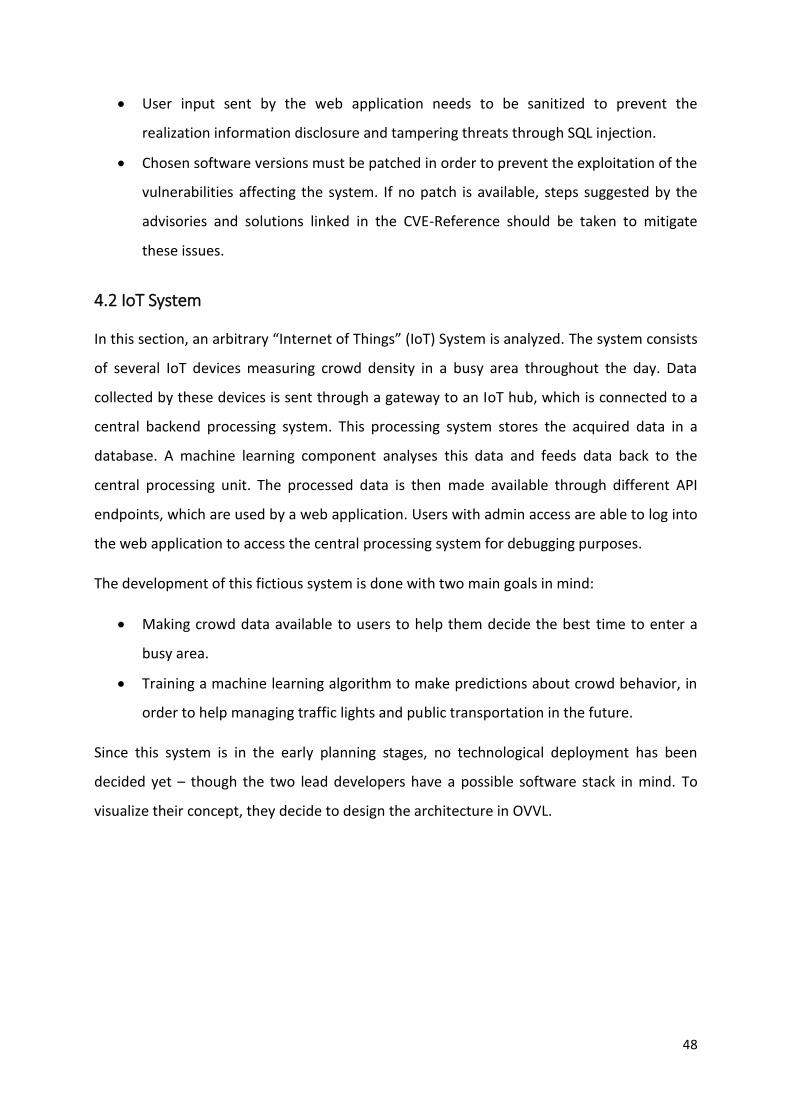
48
• User input sent by the web application needs to be sanitized to prevent the
realization information disclosure and tampering threats through SQL injection.
• Chosen software versions must be patched in order to prevent the exploitation of the
vulnerabilities affecting the system. If no patch is available, steps suggested by the
advisories and solutions linked in the CVE-Reference should be taken to mitigate
these issues.
4.2 IoT System
In this section, an arbitrary “Internet of Things” (IoT) System is analyzed. The system consists
of several IoT devices measuring crowd density in a busy area throughout the day. Data
collected by these devices is sent through a gateway to an IoT hub, which is connected to a
central backend processing system. This processing system stores the acquired data in a
database. A machine learning component analyses this data and feeds data back to the
central processing unit. The processed data is then made available through different API
endpoints, which are used by a web application. Users with admin access are able to log into
the web application to access the central processing system for debugging purposes.
The development of this fictious system is done with two main goals in mind:
• Making crowd data available to users to help them decide the best time to enter a
busy area.
• Training a machine learning algorithm to make predictions about crowd behavior, in
order to help managing traffic lights and public transportation in the future.
Since this system is in the early planning stages, no technological deployment has been
decided yet – though the two lead developers have a possible software stack in mind. To
visualize their concept, they decide to design the architecture in OVVL.
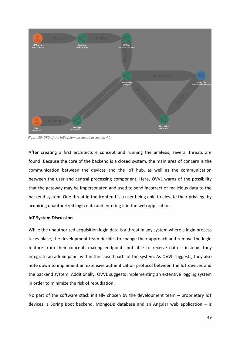
49
After creating a first architecture concept and running the analysis, several threats are
found. Because the core of the backend is a closed system, the main area of concern is the
communication between the devices and the IoT hub, as well as the communication
between the user and central processing component. Here, OVVL warns of the possibility
that the gateway may be impersonated and used to send incorrect or malicious data to the
backend system. One threat in the frontend is a user being able to elevate their privilege by
acquiring unauthorized login data and entering it in the web application.
IoT System Discussion
While the unauthorized acquisition login data is a threat in any system where a login process
takes place, the development team decides to change their approach and remove the login
feature from their concept, making endpoints not able to receive data – instead, they
integrate an admin panel within the closed parts of the system. As OVVL suggests, they also
note down to implement an extensive authentication protocol between the IoT devices and
the backend system. Additionally, OVVL suggests implementing an extensive logging system
in order to minimize the risk of repudiation.
No part of the software stack initially chosen by the development team – proprietary IoT
devices, a Spring Boot backend, MongoDB database and an Angular web application – is
Figure 35: DFD of the IoT system discussed in section 4.2.
50
linked to any CVE-References. Thus, the chosen software can be used in their current version
without any additional patches.
4.3 Discussion of the Case Studies in Respect to the Initial Requirements
The conducted case studies showcase how OVVL responds to the initial requirements, which
we derived from the current threat modeling state, as discussed in section 3.4.1. To
recapitulate, these requirements were:
1. A threat modeling tool should allow for the visualization of complex communication
systems through DFDs in an intuitive, visually appealing way.
2. It has to be possible to analyze constructed DFD for both threats and vulnerabilities.
3. DFD elements and threats must be customizable.
4. Storing threat models both online and offline has to be possible.
5. Found issues, mitigation status and model iterations must be traceable.
6. Multiple users must be able to work on a single threat model.
As the case studies show, OVVL’s MVP realizes some of these requirements already. Even
very complex systems such as System X (Section 4.1) can be visualized in a timely manner. By
providing the feature of zooming in and out of a DFD, a threat model is not limited by the
size of the system to be constructed. Additionally, the possibility of customizing DFD
elements by further specifying their properties as well as their type and CPE, increases the
possible system complexity further. The analysis of software vulnerabilities is a very helpful
feature, allowing further threat model specification. Also, while always subjective, we feel
confident in saying that – in its current design iteration – both the creation of DFDs as well as
displaying threats is more appealing and intuitive in OVVL than it is in Microsoft’s TMT.
While the tool in its current form can be used to gain a general overview over a software
system’s security properties, it is limited in some areas. During the utilization of OVVL in the
case studies it became clear, that, while already a useful feature, defining complex systems
by zooming in and out of the DFD has to be improved further by allowing for the
specification of sub-components. This would allow for a more accurate system
representation, thus improving a threat model further. Additionally, we noted that the
threat data currently available needs to be fine-tuned. In its current form, the analysis
sometimes applies threats to their respective DFD segments which are very far-fetched, or
51
too broad in their definition. In addition to further fine-tuning of our threat definitions,
realizing the requirement of custom threat definition will mitigate this issue.
When it comes to its purpose of accompanying actual software projects, some crucial
requirements are still missing. In order to fully integrate OVVL into the development
lifecycle, storing threat models both locally and online, as well as allowing the collaboration
of multiple users, must be possible. Additionally, the requirement of tracing model
iterations, mitigation status and found issues must be met.
By highlighting the importance of the set requirements, the conducted case studies aid in
the development process going forward. Currently, the MVP serves its purpose of
showcasing what the full product will offer, by making it possible to gain a general overview
over the security aspects of a software system. It constitutes a solid foundation on which
future work can build upon. The continued development is discussed further in section 5.
4.4 Modeling the Case Studies in Microsoft’s TMT
To further analyze how OVVL’s implementation responds to the requirements, we also
modeled both case studies in Microsoft’s TMT. During the modeling process, we made the
following observations:
• Microsoft’s approach of connecting elements by first adding a data flow, then
manually connecting each end to the respective elements, is significantly slower
compared to OVVL’s automatic approach of connecting elements by clicking them.
• Constructing a DFD of complex systems such as System X (Appendix C) can be
challenging, because the workspace in Microsoft’s TMT is limited. Zooming out does
not increase the space.
Thus, it took less time to construct a DFD in OVVL when compared to Microsoft’s TMT. Due
to its complexity, this time difference was especially apparent in the modeling of System X.
Because OVVL implements the same analysis methodology as Microsoft’s TMT, both tools
report the same number of threats (Figure 36). Thus, both tools offer the same extent of
threat detection. The additional vulnerability analysis offered by OVVL is not available in
Microsoft’s TMT.
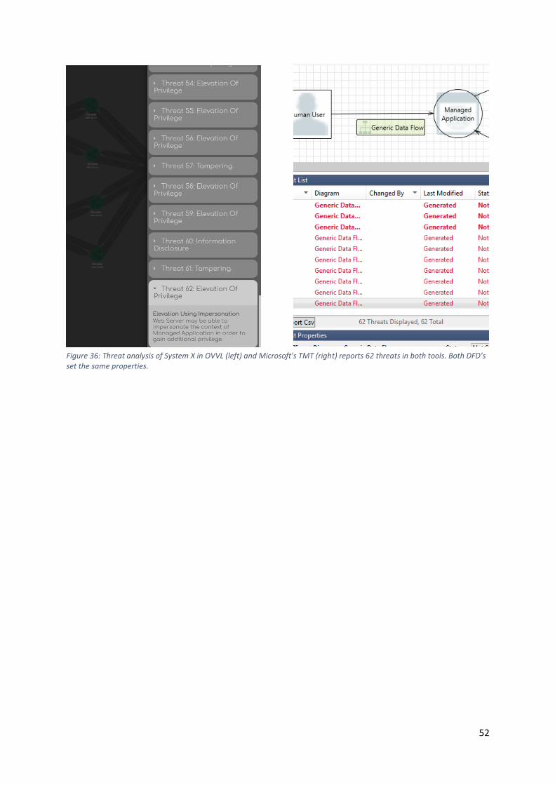
52
Figure 36: Threat analysis of System X in OVVL (left) and Microsoft's TMT (right) reports 62 threats in both tools. Both DFD’s set the same properties.
53
5. Discussion
Integrating threat modeling into the development lifecycle can be of great help in
developing secure software system. Unfortunately, its integration is often limited by a lack of
extensive tool support. The following discussion will reflect on this issue in context of the
main goals set out by this thesis: Analysis of the current threat modeling state and the
development of the new threat modeling tool OVVL.
Threat Modeling
Threat modeling is the concept of deconstructing a software architecture into its basic
components and analyzing the communication flow of these components for threats relating
to IT security. A threat model can be built for any system which can be broken down into a
DFD, analyzing it in regard to its IT security properties. The fact, that 50% of security flaws
within software systems arise during their designing phase [12, p. 53], makes threat
modeling especially useful in the early stages of development. But it is not limited just to the
designing phase of a project – developing threat model iterations parallel to the
development lifecycle reveals the mitigation status of initial design flaws and possible
security issues arising from earlier mitigations.
Current State of Threat Modeling
The current state of threat modeling does not seem to reflect the scope it should utilize,
leaving many demands unmet [32, p. 13]. While several enterprise applications offering
threat modeling support exist, their pricing options constitute a barrier of entry especially
for smaller development teams. This is due to the fact that arising issues within software
systems are often erroneously not put in causal dependency to their architectural design
[62, p. 5], and thus enterprise threat modeling software might not be seen worth their price
tag. Thus, it might make more sense for smaller software projects to utilize one of the freely
available tools.
54
Microsoft TMT
Here, Microsoft’s “Threat Modeling Tool” is the contender offering the widest feature
palette. While a great tool, it is lacking in some areas. One major drawback is a missing
focus on modern design and layout. This might confuse a user, thus not only making it hard
to create threat models in a timely manner, but also to present an architectural analysis to
other team members. When viewed from a functional standpoint, the lack of custom
threats, mitigation status and version tracking might aggravate to justify using it as a tool
accompanying the development lifecycle. Last but not least, it being dependent on the
windows platform is an additional drawback.
OVVL
Based on this, two assumptions can be made: First, the demand for free threat modeling
tools is not satisfied. Second, a new tool must offer functionalities similar to existing ones
and improve on certain areas. Following this train of thought, in the context of this thesis a
concept for a new threat modeling tool – called OVVL – was designed. It includes a general
design and UX concept, as well as a feature backlog. While in the future a tool implementing
the full extent of the concept will be built, the MVP of OVVL developed during the course of
this thesis offers a first impression on how this tool will improve the threat modeling state
and rival existing tools. The MVP couples a modern design approach with the core features
required for threat modeling: DFD creation, DFD element properties and threat analysis. It is
developed in form of a web application, thus offering platform independence.
CPE and CVE-References Feature Discussion
Compared to existing solutions, the MVP also goes a step further in offering the specification
of software makes and analyzing them for their respective vulnerabilities. While looking up
software makes and corresponding vulnerabilities already was possible externally through
the search engine offered by the NVD [20], our approach offers a decrease of loading times
of about 83% for CPE queries and about 71% for CVE queries (Table 3)6.
6 A detailed breakdown of the loading times is shown in Appendix B. It must be noted that the loading times shown in Table 3 include the content download time. It differs by about 200 milliseconds between requests of OVVL and the NVD. This is due to the fact that in OVVL queries a JSON object is returned, while queries in the NVD return a HTML document.
55
The fact that the NVD only returns 20 results at a time, with further requests being sent out
for additional results, could be considered an even bigger decrease in loading times in OVVL.
Table 3: Comparison of the loading times of both the “Windows 10 64-bit” CPE and the derived CVE search query between OVVL and the NVD [20]. Values are displayed in milliseconds (ms) and rounded to the nearest integer.
OVVL NVD
CPE Query 279 ms 1620 ms
CVE Query 448 ms 1570 ms
Additionally, the tool combines the lookup of vulnerabilities with the linking of software
makes to multiple DFD elements in a single workspace context. This significantly reduces the
number of steps which need to be taken in order to analyze a software system for
vulnerabilities.
Possible Improvements to OVVL
While the MVP can already be considered an improvement to the current threat modeling
state, some enhancements need to be made. Still missing is the concept of model iterations
and mitigation status of threats, as well as user management and the definition of custom
threats. These improvements are somewhat dependent on each other and will be
implemented in the months following this thesis.
Utilization of OVVL in Lectures
OVVL is planned to be utilized as part of future teaching activities at Bachelor and Master
level at the University of Applied Sciences Offenburg. These teaching activities include areas
of IT security and software development. In these areas, OVVL can assist in pointing out the
importance of threat modeling and “Security by Design”, as well as in teaching about
software architectures and distributed systems in general.
Licensing
In the future, we plan on making OVVL open-source under the Apache License 2.0 [63]. This
means, amongst other things, that the tool can be freely used commercially, modified and
distributed. An open-source approach allows for additional community development – thus
56
further improving the tool. While we have not decided on a financial concept, several
possibilities are imaginable:
• Continuing development sponsored through third-party funds, possibly including
crowdfunding options.
• Offering the basic version of the application for free, while keeping certain features
under a proprietary license.
• Offering support and/or consulting work, aiding development projects in integrating
OVVL into development lifecycles.
57
6. Conclusion
By utilizing threat modeling during the design phase of a system, as well as during its
development lifecycle, IT security flaws can be mitigated before they arise in a production
system. As a result, the demand for tools offering threat modeling support is ramping up,
but not addressed adequately by existing solutions. Especially factors such as a limited
functionality, platform dependence, or a dated design can make it challenging to justify
integrating existing tools into the development process. By analyzing the lacking areas of
existing tools in detail, but also taking into accounts their positive aspects, several
requirements for a new tool could be derived. An MVP of this new tool, which we call OVVL,
was developed during the course of this thesis. Even though in its current form only the
features we prioritized the highest are implemented, it still offers the key features needed
for threat modeling. By offering a web application, which combines an extensive threat
analysis with an additional vulnerability analysis and an intuitive design, we showcase how
the lacking areas of the threat modeling state can be filled. The MVP lays the foundation for
future development, which we hope will be enhanced further through community
involvement, by making OVVL open source. We think that this open source approach,
coupled with the wide array of features OVVL will be offering, will make this tool a
meaningful contender in the world of threat modeling. With the increasing importance of
developing secure software systems, integrating the approach of “Security by Design” as a
core concept into the development lifecycle will greatly benefit software projects of any size.
By being simple in its structure, yet powerful in its functionality, OVVL will aid in utilizing this
mindset. As such, we are hopeful that OVVL will improve the current state of threat
modeling.
58
7. References
[1] Georgi Popov, Bruce K. Lyon, and Bruce Hollcroft, Risk Assessment: A Practical Guide to
Assessing Operational Risks, 1st ed. s.l.: Wiley, 2016.
[2] Natalija Vlajic, Security Risk Management. (2013), Available:
https://www.eecs.yorku.ca/course_archive/2013-
14/F/4482/CSE4482_03_SecurityRiskManagement_2013_posted.pdf. Accessed on: Nov. 26
2018.
[3] The OWASP Foundation, OWASP Risk Rating Methodology. (n.d.) [Online] Available:
https://www.owasp.org/index.php/OWASP_Risk_Rating_Methodology. Accessed on: Nov. 26
2018.
[4] News. [Online] Available: https://www.pivotpointsecurity.com/wp-
content/uploads/2016/08/Updated-Risk-Matrix.jpg.
[5] CAST, Why Is Software Risk Management Essential to Companies Today? (2018) [Online]
Available: https://www.castsoftware.com/glossary/software-risk-management. Accessed on:
Nov. 26 2018.
[6] Debarghya Pandit, Threat Modeling: The Why, How, When and Which Tools. (n.d.) [Online]
Available: https://devops.com/threat-modeling-the-why-how-when-and-which-tools/. Accessed
on: Nov. 27 2018.
[7] Secodis GmbH, Threat Modeling. (n.d.) [Online] Available:
https://www.secodis.com/bedrohungsanalysen/. Accessed on: Nov. 27 2018.
[8] Zhendong Ma and Christoph Schmittner, “Threat Modeling for Automotive Security Analysis”
(2016), in Advanced Science and Technology Letters Vol. 139, pp. 333–339.
[9] Peter Stavroulakis and Mark Stamp, Handbook of Information and Communication Security.:
Springer, 2010.
[10] Suvda Myagmar, Adam J. Lee, and William Yurcik, Threat Modeling as a Basis for Security
Requirements. IEEE Symposium on Requirements Engineering for Information Security, 2005
[11] Microsoft Corporation, Microsoft Threat Modeling Tool 2016. [Online] Available:
https://www.microsoft.com/en-us/download/details.aspx?id=49168. Accessed on: Dec. 03
2018.
[12] Greg Hoglund and Gary McGraw, Exploiting Software: How to break code: Addison Wesley,
2004.
[13] Loren Kohnfelder and Praerit Garg, The threats to our products.
[14] Adam Shostack, Experiences Threat Modeling at Microsoft. (2008) [Online] Available:
https://adam.shostack.org/modsec08/Shostack-ModSec08-Experiences-Threat-Modeling-At-
Microsoft.pdf. Accessed on: Jan. 29 2019.
[15] US-CERT, Security Tip (ST04-015): Understanding Denial-of-Service Attacks. (2009)
[16] Andreas Schaad and Mike Borozdin, “TAM2: Automated Threat Analysis” (2012), in SAC '12
Proceedings of the 27th Annual ACM Symposium on Applied Computing, pp. 1103–1108.
[17] National Vulnerability Database, Official Common Platform Enumeration (CPE) Dictionary.
[Online] Available: https://nvd.nist.gov/products/cpe. Accessed on: Nov. 14 2018.
[18] National Vulnerability Database, CPE Summary. Available:
https://nvd.nist.gov/products/cpe/detail/334460?keyword=windows+7+64+bit&status=FINAL&
orderBy=CPEURI&namingFormat=2.3. Accessed on: Nov. 29 2018.
[19] The MITRE Corporation, CVE - Common Vulnerabilities and Exposure. [Online] Available:
https://cve.mitre.org/. Accessed on: Nov. 28 2019.
[20] National Vulnerability Database. [Online] Available: https://nvd.nist.gov/. Accessed on: Nov. 29
2018.
59
[21] FIRST.org, Inc., Common Vulnerability Scoring System SIG. [Online] Available:
https://www.first.org/cvss/. Accessed on: Nov. 29 2018.
[22] National Vulnerability Database, CVE-2018-8505 Detail. [Online] Available:
https://nvd.nist.gov/vuln/detail/CVE-2018-8505.
[23] Microsoft Corporation, Microsoft Threat Modeling Tool 2016: Getting Started Guide. (n.d.)
[24] Stack Overflow, Developer Survey Results 2018: Platforms. (2018) [Online] Available:
https://insights.stackoverflow.com/survey/2018/#technology-platforms. Accessed on: Dec. 05
2018.
[25] OWASP, Threat Dragon. [Online] Available: http://docs.threatdragon.org/. Accessed on: Dec. 06
2018.
[26] github.com, owasp-threat-dragon-desktop Master Branch. [Online] Available:
https://github.com/mike-goodwin/owasp-threat-dragon-desktop/commits/master. Accessed
on: Dec. 06 2018.
[27] OWASP, OWASP Threat Dragon: Roadmap. [Online] Available:
https://www.owasp.org/index.php/OWASP_Threat_Dragon#Roadmap. Accessed on: Dec. 06
2018.
[28] ThreatModeler, ThreatModeler. [Online] Available: https://threatmodeler.com/threat-
modeling-methodologies/. Accessed on: Dec. 09 2018.
[29] Continuum Security, IriusRisk. [Online] Available: https://continuumsecurity.net/threat-
modeling-tool/. Accessed on: Dec. 09 2018.
[30] foreseeti, securiCAD. [Online] Available: https://www.foreseeti.com/.
[31] Smartsheet, Everything You Need to Know About Product Owners for Scrum and Agile Teams.
(n.d.) [Online] Available: https://www.smartsheet.com/everything-you-need-know-about-
product-owners. Accessed on: Dec. 30 2018.
[32] Josh Brown-White et al., Tactical Threat Modeling. (2017) [Online] Available:
https://www.safecode.org/wp-content/uploads/2017/05/SAFECode_TM_Whitepaper.pdf.
Accessed on: Dec. 11 2018.
[33] National Institute of Standards and Technology. [Online] Available: https://www.nist.gov/.
Accessed on: Dec. 27 2018.
[34] Atlassian, Jira Software. [Online] Available: https://www.atlassian.com/software/jira. Accessed
on: Dec. 29 2018.
[35] FogBugz. [Online] Available: https://www.fogbugz.com/. Accessed on: Dec. 29 2018.
[36] Angular, Angular. [Online] Available: https://angular.io/. Accessed on: Dec. 25 2018.
[37] Angular, Angular Contributors. [Online] Available: https://angular.io/about?group=Angular.
Accessed on: Dec. 25 2018.
[38] Angular, Architecture overview. (n.d.) [Online] Available: https://angular.io/guide/architecture.
Accessed on: Dec. 25 2018.
[39] Angular, Component Styles. (n.d.) [Online] Available: https://angular.io/guide/component-
styles. Accessed on: Dec. 26 2018.
[40] Mircrosoft, TypeScript. (n.d.) [Online] Available: https://www.typescriptlang.org/. Accessed on:
Dec. 27 2018.
[41] Dan Abramov and Redux documentation authors, Redux: A predictable state container for
JavaScript apps. (n.d.) [Online] Available: https://redux.js.org/. Accessed on: Dec. 30 2018.
[42] Spring Framework, Introduction to Spring Framework: Part I. Overview of Spring Framework.
(n.d.) [Online] Available: https://docs.spring.io/spring/docs/3.0.x/spring-framework-
reference/html/overview.html. Accessed on: Dec. 26 2018.
[43] Zoltán Raffai, Getting Started With Java Spring: What is Spring boot? (2018) [Online] Available:
https://www.zoltanraffai.com/blog/what-is-spring-boot/. Accessed on: Dec. 27 2018.
60
[44] Spring Framework, 16.10 Convention over configuration: 16. Web MVC framework. (n.d.)
[Online] Available: https://docs.spring.io/spring/docs/3.0.0.M3/reference/html/ch16s10.html.
Accessed on: Dec. 26 2018.
[45] Swagger, About Swagger. (n.d.) [Online] Available: https://swagger.io/about/. Accessed on: Dec.
27 2018.
[46] MongoDB Inc., The MongoDB 4.0 Manual. (n.d.) [Online] Available:
https://docs.mongodb.com/manual/. Accessed on: Dec. 27 2018.
[47] Prashanth Jayaram, When to Use (and Not to Use) MongoDB. (2016) [Online] Available:
https://dzone.com/articles/why-mongodb. Accessed on: Dec. 27 2018.
[48] National Vulnerability Database, Search Common Platform Enumerations. [Online] Available:
https://nvd.nist.gov/products/cpe/search. Accessed on: Dec. 27 2018.
[49] The Internet Society, Hypertext Transfer Protocol -- HTTP/1.1. (1999) [Online] Available:
https://tools.ietf.org/html/rfc2616.
[50] Ecma International, ECMA-404: The JSON Data Interchange Syntax. (2017) [Online] Available:
https://www.ecma-international.org/publications/files/ECMA-ST/ECMA-404.pdf. Accessed on:
Jan. 02 2019.
[51] Sebastian Eschweiler, Learn Redux - Introduction to State Management With React: How State
Management Solves The Problem. (2017) [Online] Available:
https://medium.com/codingthesmartway-com-blog/learn-redux-introduction-to-state-
management-with-react-b87bc570b12a. Accessed on: Dec. 30 2018.
[52] Sebastian Eschweiler, Learn Redux - Introduction to State Management With React: The Problem
With Traditional MVC Architecture. (2017) [Online] Available:
https://medium.com/codingthesmartway-com-blog/learn-redux-introduction-to-state-
management-with-react-b87bc570b12a. Accessed on: Dec. 30 2018.
[53] Redux GitHub Repository, Redux: Before Proceeding Further. (n.d.) [Online] Available:
https://github.com/reduxjs/redux/. Accessed on: Dec. 30 2018.
[54] GitHub Inc. [Online] Available: https://github.com/. Accessed on: Feb. 01 2019.
[55] Heroku. [Online] Available: https://www.heroku.com/. Accessed on: Jan. 03 2019.
[56] Amazon Web Services. [Online] Available: https://aws.amazon.com/de/. Accessed on: Jan. 03
2019.
[57] Shane Rostad, Heroku vs AWS - Why Costs and Scale are Secondary Considerations. (2018)
[Online] Available: https://trifinlabs.com/heroku-vs-aws/. Accessed on: Jan. 03 2019.
[58] Cleveroad, Heroku vs AWS: Which Cloud Platform to Choose in 2018?: AWS vs Heroku pricing.
(n.d.) [Online] Available: https://www.cleveroad.com/blog/heroku-vs-aws--which-cloud-based-
solution-to-choose-. Accessed on: Jan. 03 2019.
[59] Chris Ward, What Is Continuous Integration?: Continuous Integration: Automating Development
Processes and Best Practices. (2018) [Online] Available:
https://www.exoscale.com/syslog/what-is-continuous-integration/. Accessed on: Jan. 03 2019.
[60] Ben Sandofsky, Understanding the Git Workflow. (n.d.) [Online] Available:
https://sandofsky.com/blog/git-workflow.html. Accessed on: Jan. 03 2019.
[61] Andreas Schaad, “SystemX – Specification” (n.d.), Enterprise and IT Security (ENITS) - Security in
Distributed Computing Laboratory, Hochschule Offenburg.
[62] Iván Arce et al., Avoiding the Top 10 Software Security Design Flaws. (n.d.) [Online] Available:
https://www.computer.org/cms/CYBSI/docs/Top-10-Flaws.pdf.
[63] The Apache Software Foundation, Apache License: Version 2.0. (2004) [Online] Available:
https://www.apache.org/licenses/LICENSE-2.0. Accessed on: Jan. 30 2019.
61
Appendix A: Design Guideline OVVL
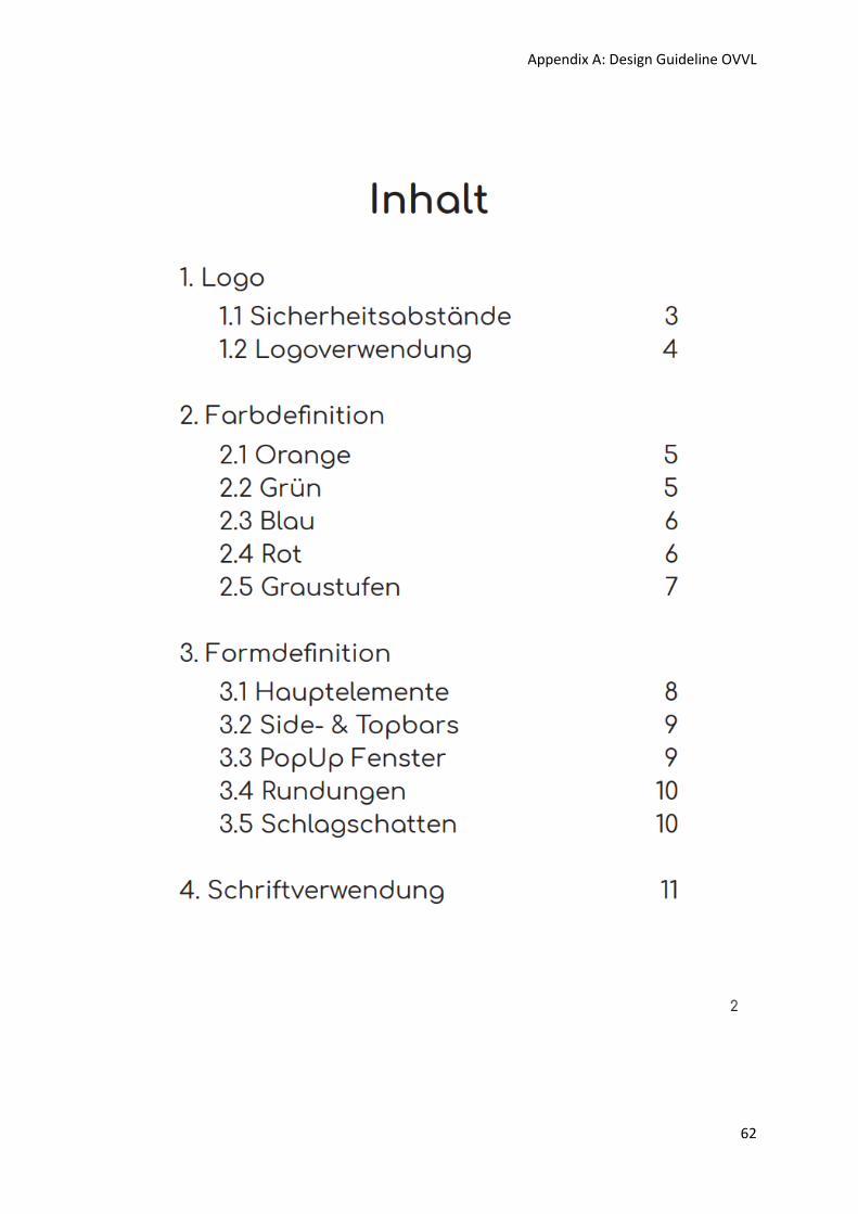
Appendix A: Design Guideline OVVL
62
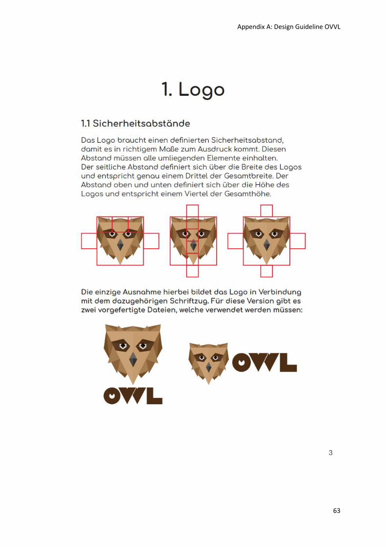
Appendix A: Design Guideline OVVL
63
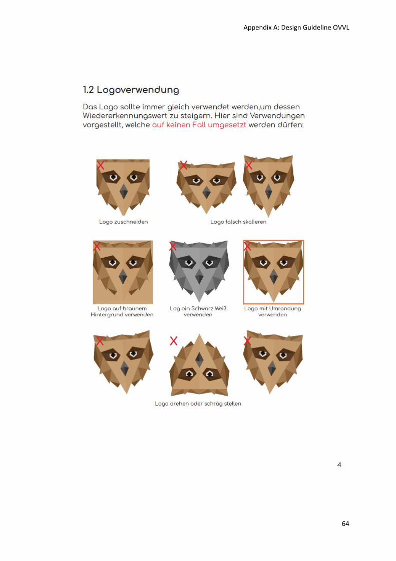
Appendix A: Design Guideline OVVL
64
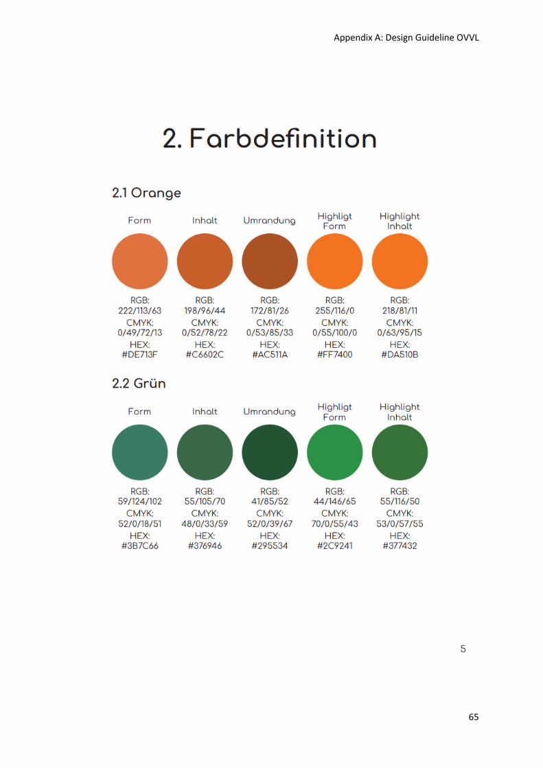
Appendix A: Design Guideline OVVL
65
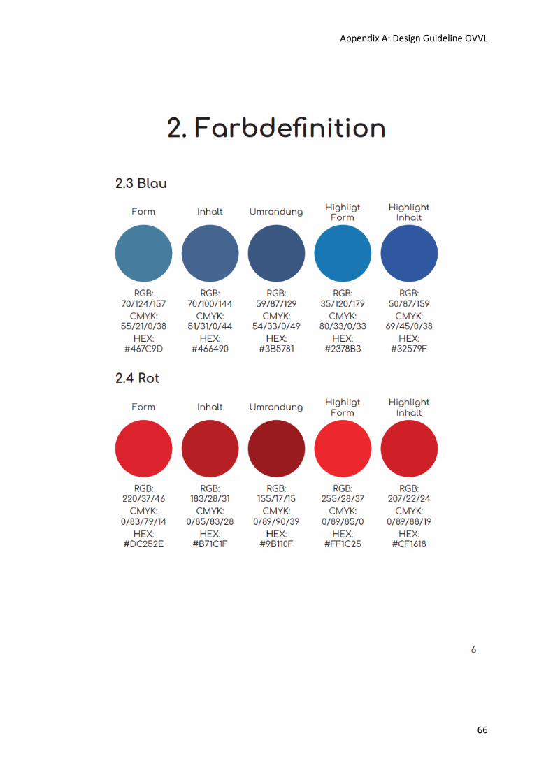
Appendix A: Design Guideline OVVL
66
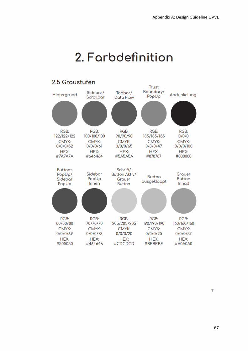
Appendix A: Design Guideline OVVL
67
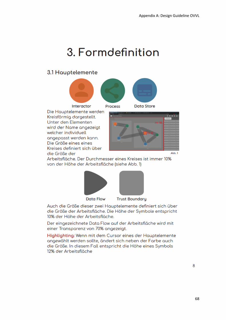
Appendix A: Design Guideline OVVL
68
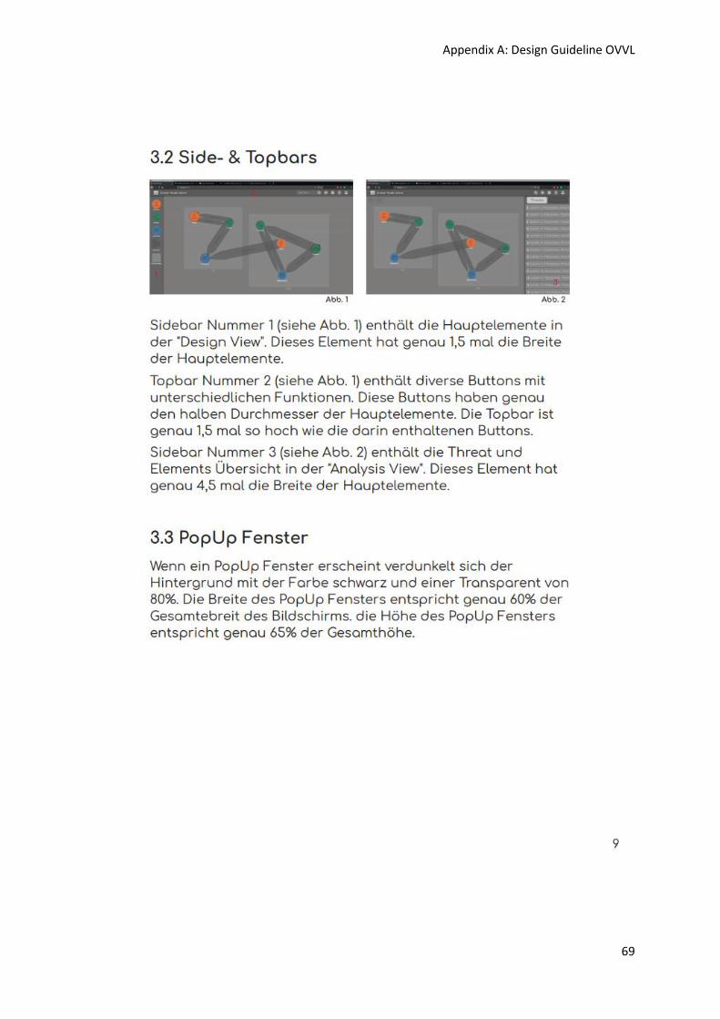
Appendix A: Design Guideline OVVL
69
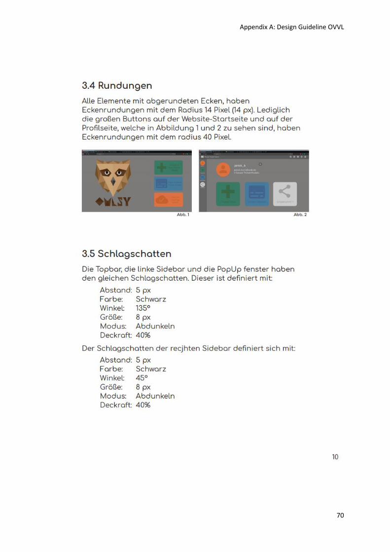
Appendix A: Design Guideline OVVL
70
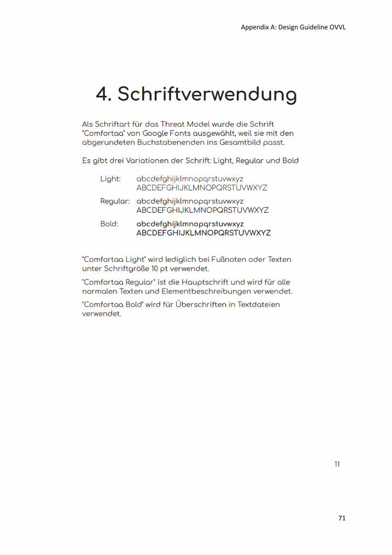
Appendix A: Design Guideline OVVL
71
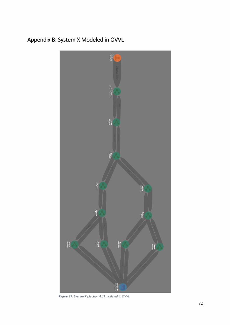
72
Appendix B: System X Modeled in OVVL
Figure 37: System X (Section 4.1) modeled in OVVL.
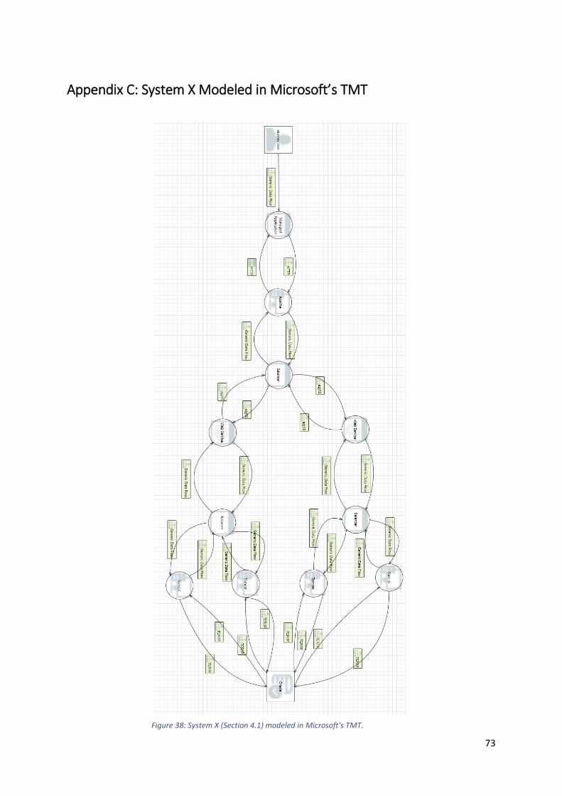
73
Appendix C: System X Modeled in Microsoft’s TMT
Figure 38: System X (Section 4.1) modeled in Microsoft's TMT.
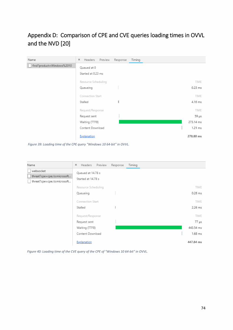
74
Appendix D: Comparison of CPE and CVE queries loading times in OVVL
and the NVD [20]
Figure 39: Loading time of the CPE query "Windows 10 64-bit" in OVVL.
Figure 40: Loading time of the CVE query of the CPE of "Windows 10 64-bit" in OVVL.
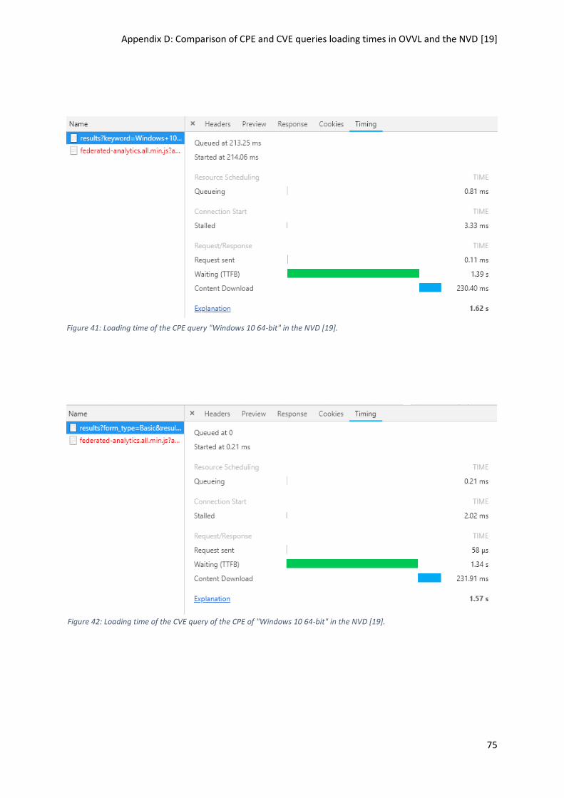
Appendix D: Comparison of CPE and CVE queries loading times in OVVL and the NVD [19]
75
Figure 41: Loading time of the CPE query "Windows 10 64-bit" in the NVD [19].
Figure 42: Loading time of the CVE query of the CPE of "Windows 10 64-bit" in the NVD [19].

76
Declaration of Independent Work
I, Tobias Reski, confirm that the work for this Bachelor Thesis with the title: "Conception and
Development of a Threat Modeling Tool”, was solely undertaken by myself and that no help
was provided from other sources as those allowed.
All sections of the paper that use quotes or describe an argument or concept developed by
another author have been referenced, including all secondary literature used, to show that
this material has been adopted to support my thesis.
Place / Date Signature