Embed Size (px)
Citation preview

Concept of Operations for the
Airborne Collision A voidance System X
ACAS X CONOPS Version 1 Revision 1
October 5, 2012
Traffic Alert & Collision A voidance System (TCAS) Program Office (PO)
Prepared By 1 ~~~ / Mike"C~~~-Mike Castle, Date: 04-0ct-2012
Date: 09-0ct-2012

Concept of Operations for the Airborne Collision Avoidance System X | V1 R1
ACAS_X_CONOPS_V1_R1 Page ii
REVISION HISTORY
Vers. Rev. Sect. Description of Change Author / Editor/ CM Release Date
1 0 N/A CM Release E. Walters 22-Mar-20121.3.4
67.6
Cover Deleted acronym from document title. Corrected PO name.
Cover Updated CM Identifier from "CAS CONOPS" to "ACAS X CONOPS" to match title page.*
0 Synchronized colors and fonts for captions of figures and tables .
0 Updated TOC to match edits.
1.1Reconfigured Section 1 for consistency with other CI's: Purpose, Scope, Context, Background. Moved text from old 1.1 and 1.2. Added text as needed to fill.
1.2 Added explanation of ICAO use of term ACAS and relation to use in this doc.
2.1Corrected Figure 1 - Illustration of ICAO CMS, including CA. Added Figure 2 Decomposition of CA. Corrected use of CA, CAS, and ACAS throughout.
2.2 Deleted the seven generally accepted operational performance goals. Moved to ACAS PRD V1.
1 1 N/A CM Release E. Walters 9-Oct-2012
1 0
1 0 5-Oct-2012E. Walters
Deleted minimum equipage constraints (dual receivers) for ACAS XA
4-Oct-2012M. Castle
Federal Aviation Administration 800 Independence Avenue, SW
Washington, DC 20591

Concept of Operations for the Airborne Collision Avoidance System X | V1 R1
ACAS_X_CONOPS_V1_R1 Page iii
EXECUTIVE SUMMARY
The Federal Aviation Administration’s Collision Avoidance Program Office is developing an advanced Airborne Collision Avoidance System (ACAS), called ACAS X, to support the objectives of the Next Generation Air Transportation System Program (NextGen). This Concept of Operations document is intended to lay forth the expected system concepts and design principles. A summary of the background for the Collision Avoidance (CA) within the National Airspace System (NAS) is described, as well as an overview of Traffic Alert and Collision Avoidance System (TCAS), the currently mandated line of ACAS. TCAS II has been very successful in reducing the risk of mid-air collisions. However, despite the success of the TCAS program, there remain areas for improvement. The limitations have to do with the adaptability and flexibility of TCAS II to new users, new operations and separations, and new surveillance sources. The outcome of this inflexibility is to prolong update cycles and to limit new users and new capabilities. In the alternatives studied, which included updating TCAS II, or using probability thresholding, deterministic path planning, or optimized logic, the optimized logic approach provides the most adaptable and beneficial framework for future CA. The new system, called ACAS X, will have variants called ACAS XA and ACAS XP, which refer to the means by which they perform the surveillance and coordination functions – XA will have active means to collect that data, where XP will acquire the information passively. Examples of active and passive surveillance that could be incorporated into ACAS X would be the TCAS interrogator/receiver and ADS-B transceivers, respectively. It is expected that aircraft currently equipped with TCAS would choose to equip with ACAS XA and that General Aviation aircraft may equip with ACAS XP. In addition, other variants of ACAS X for specific NextGen operations and Unmanned Aerial Systems are touched on in the document. In terms of stakeholder impact, ACAS XA systems will look to improve on the performance of TCAS II – improving safety and reducing unnecessary alerts while providing the same procedures and operational interaction as current TCAS. It is expected that manufacturers may benefit from the ACAS X optimized logic architecture so that change cycles and updates are shortened. It is expected that new user classes for CA will emerge in the wake of the adaptable logic, and that the interoperability of CA in NextGen operations will be improved for operators and Air Navigation Service Providers and Air Traffic Control.

Concept of Operations for the Airborne Collision Avoidance System X | V1 R1
ACAS_X_CONOPS_V1_R1 Page iv
ACKNOWLEDGEMENTS\
Special thanks to the following individuals and organizations that provided content to this document or participated in analysis, review, and editing.
Last Name First Name OrganizationBachman Larry RegulusCarpenter Ken ContractorCastle Mike Aurora SciencesDrumm Ann MIT Lincoln LaboratoryElder Tomas MIT Lincoln LaboratoryGray David Federal Aviation AdministrationKochenderfer Mykel MIT Lincoln LaboratoryOlson Wesley MIT Lincoln LaboratoryHolland Jessica MIT Lincoln LaboratoryPlummer Steve Federal Aviation AdministrationSearight Stuart Federal Aviation AdministrationSilbermann Joshua JHU Applied Physics LaboratorySuchy Neal Federal Aviation AdministrationTillotson Daniel ARINCTroast Tom RegulusWalters Ethan Aurora SciencesZeitlin Andy MITRE

Concept of Operations for the Airborne Collision Avoidance System X | V1 R1
ACAS_X_CONOPS_V1_R1 Page v
Table of Contents 1.0 Introduction ..............................................................................................................................1
1.1 Purpose ...........................................................................................................................1 1.2 Scope ..............................................................................................................................1 1.2 Context ...........................................................................................................................2 1.3 Stakeholder Impact ........................................................................................................2
1.3.1 Pilots / Flight Crew .........................................................................................2 1.3.2 New User Classes ...........................................................................................3 1.3.3 Controllers.......................................................................................................3 1.3.4 Manufacturers .................................................................................................4 1.3.5 Aircraft Operators ...........................................................................................4 1.3.6 Air Navigation Service Providers ...................................................................4
1.4 Document Overview ......................................................................................................5 2.0 Background ..............................................................................................................................6
2.1 Conflict Management System ........................................................................................6 2.2 Collision Avoidance System ..........................................................................................7 2.3 Traffic Alert and Collision Avoidance System ..............................................................8
3.0 Justification for Change ..........................................................................................................9 3.1 Technical Limitations of the Current System ................................................................9
3.1.1 Insufficient Flexibility to Surveillance Changes .............................................9 3.1.2 Insufficient Adaptability .................................................................................9 3.1.3 Limitations to Vertical Maneuvering ..............................................................9 3.1.4 Operationally Undesirable Consequences ......................................................8
3.2 Impacts of the Technical Shortfalls .............................................................................10 3.2.1 Unnecessary Resolution Advisories .............................................................10 3.2.2 Operationally Undesirable Consequences ....................................................11 3.2.3 Long Update Cycles ......................................................................................11 3.2.4 Limitations to NextGen Operations ..............................................................11 3.2.5 Limited Use of ADS-B Surveillance Data ....................................................12 3.2.6 No Collision Avoidance for General Aviation .............................................13 3.2.7 Difficulty in Incorporating Unmanned Aircraft Collision Avoidance ..........13
4.0 ACAS Alternatives .................................................................................................................14 4.1 Modifications to Existing TCAS Logic .......................................................................14 4.2 Deterministic Path Planning ........................................................................................15

Concept of Operations for the Airborne Collision Avoidance System X | V1 R1
ACAS_X_CONOPS_V1_R1 Page vi
4.3 Probability Thresholding .............................................................................................16 4.4 Decision Theoretic Planning (Optimized Threat Logic) .............................................18 4.5 Summary and Comparison ...........................................................................................18
5.0 Justification for ACAS X.......................................................................................................19 5.1 Increased Flexibility for NextGen Operations .............................................................19 5.2 Increased Adaptability for NextGen Surveillance Inputs ............................................19 5.3 Reduced Collision Risk................................................................................................20 5.4 Collision Avoidance Capability for General Aviation Aircraft ...................................20
6.0 Protection Provided by Collision Avoidance .......................................................................21 6.1 Operational Collision Avoidance Categories...............................................................21 6.2 Overview of CA Encounters ........................................................................................22
6.2.1 Collision Avoidance between Aircraft using ASC .......................................22 6.2.2 Collision Avoidance between Aircraft using ASC and PSC ........................23 6.2.3 Collision Avoidance between Aircraft using ASC and NoCAS ...................26 6.2.4 Collision Avoidance between Aircraft using PSC .......................................26 6.2.5 Encounters between Passive CAS Equipped and NoCAS Aircraft ..............27
6.3 CAS Protection in “Rule” and non-“Rule” Airspaces .................................................27 7.0 Proposed System ....................................................................................................................30
7.1 Overview ......................................................................................................................30 7.2 Future Avionics Equipage............................................................................................31 7.3 Interfaces to External Systems .....................................................................................33 7.4 System Concepts ..........................................................................................................33
7.4.1 Surveillance & Tracking Module ..................................................................33 7.4.2 Centralized Tracking .....................................................................................35 7.4.3 Optimized Threat Logic Concepts ................................................................35 7.4.4 Display and Annunciation.............................................................................36
7.5 Constraints and Key Assumptions ...............................................................................37 8.0 Verification and Validation ...................................................................................................38
8.1 System Verification .....................................................................................................38 8.2 Safety Validation .........................................................................................................40 8.3 Operational Suitability .................................................................................................41 8.4 Implementing Change in Deployed Systems ...............................................................42
9.0 Acronyms ................................................................................................................................44 10.0 References .............................................................................................................................46

Concept of Operations for the Airborne Collision Avoidance System X | V1 R1
ACAS_X_CONOPS_V1_R1 Page 1
1.0 Introduction 1.1 Purpose
This document provides the Concept of Operations (CONOPS) for the Airborne Collision Avoidance System X (ACAS X). This includes a high-level overview of the operational goals, processes, constraints, responsibilities, and impacts of ACAS X implementation. It may also be used to coordinate the expectations of the FAA and its associated stakeholders. This CONOPS is a living document that will be revised over time as the concept develops and solidifies.
1.2 Scope The scope of this document is ACAS X, the next line of ACAS currently being developed by the TCAS Program Office (PO) of the Federal Aviation Administration (FAA). Several variants of ACAS X are envisioned. These include:
ACAS “XA” refers to the “active” surveillance variant, which always have the capability to utilize “active” 1030/1090 interrogation/reply surveillance techniques as well as information from Automatic Dependent Surveillance – Broadcast (ADS-B). The basic operation of ACAS XA will resemble current TCAS II systems, which issue Traffic Advisories (TAs – indications on a traffic display and aurally provided to the pilot that another aircraft is in the immediate vicinity) and Resolution Advisories (RAs – a display indication given to the pilot recommending a maneuver to either increase or maintain the existing vertical separation relative to an intruding aircraft). However, new surveillance and data processing techniques are used to optimize the safety and suitability of the CA system. ACAS “XP” refers to “passive” surveillance variant, described in this document, which does not use active interrogation/reply protocols, but instead uses only ADS-B surveillance to perform collision avoidance. ACAS XP will also issue RAs and TAs when appropriate, but the system is geared towards aircraft that would not otherwise equip with TCAS or a CAS system. ACAS “XO” is the variant used for selected Next Generation Air Transportation System (NextGen) operations that, if undertaken with standard ACAS XA or ACAS XP logic alone, may generate an unacceptable rate of RAs. One example of such an application might be aircraft participating in Closely Spaced Parallel Operations (CSPO), including both departures and arrivals. ACAS XO will provide the same safety benefit to operations, while also removing unnecessary alerts for participating aircraft in the operation, which may be closer than typical in most NAS operations. XO performance will apply to a subset of aircraft performing the operations through some means of ‘selection’; other aircraft not selected will interact with ownship as ACAS XA or XP.

Concept of Operations for the Airborne Collision Avoidance System X | V1 R1
ACAS_X_CONOPS_V1_R1 Page 2
ACAS XU is the name given to the ACAS X variant customized for Unmanned Aerial Systems (UAS). It is similar to ACAS XA and XP, but allows for new surveillance systems, operation, and actions (for example, UAS may have automated response and might allow for horizontal maneuvering as well as vertical).
1.3 Context “ACAS” is a generic acronym of the International Civil Aviation Organization (ICAO) for the specific line of avionics that is certified to provide decision support to pilots during encounters with other aircraft when there is an imminent risk of collision. The first globally harmonized ACAS design configuration was ACAS I (no variants) followed by ACAS II (v.6.04, v7.0, v7.1, v7.2). These are referred to as TCAS I and TCAS II in the United States (U.S.). TCAS I and TCAS II are only discussed in this document for purposes of background and comparison. When the term “ACAS” is used absent a roman numeral, the reader may assume the generic usage as given by ICAO. When used with a roman numeral, the reader should infer both the US and EU lines since the internationally agreed standards are identical. Otherwise, the reader should assume the specific system variant specified in the text. The conceptual basis for the optimized threat resolution logic at the heart of ACAS X began in 2008 at the Massachusetts Institute of Technology (MIT) Lincoln Laboratory (LL) [3,11,12]. Each ACAS X variant will be prototyped concurrently with the development of its expected requirements. These initial requirements, initial design and validation analyses will serve as input to the RTCA/EUROCAE standards development process once the decision is made to begin full scale development activities. The output of that process will be a new Minimum Operational Performance Standard (MOPS) for ACAS X that manufacturers can use to develop, certify, and produce equipment for aircraft operators. Unlike previous CA development efforts which led to equipage mandates, it is anticipated that ACAS X users will voluntarily equip. For existing Traffic Alert and Collision Avoidance System (TCAS) users, ACAS X is being developed to facilitate operations in the current and future airspace that are incompatible with existing TCAS alerting criteria. For users not currently equipped with TCAS (e.g. many of the general aviation community), ACAS X will provide a safety benefit that is not currently available. Additionally, ACAS X is designed to be compatible with legacy and future surveillance systems as well as existing TCAS. Thus, it is anticipated that civil aviation authorities will not need to mandate ACAS X; instead those users accruing a benefit will equip voluntarily.
1.4 Stakeholder Impact The impacts that ACAS X is expected to have on pilots and flight crews, potential new users of ACAS X, air traffic controllers, avionics manufacturers, aircraft operators, and air navigation system providers are summarized in the paragraphs below.
1.4.1 Pilots / Flight Crews

Concept of Operations for the Airborne Collision Avoidance System X | V1 R1
ACAS_X_CONOPS_V1_R1 Page 3
Compared with current versions of TCAS II, flight crew interaction and response protocols with ACAS XA will remain unchanged. Like TCAS II, ACAS XA equips pilots with tools to avoid collisions using a situational awareness traffic display, traffic and resolution advisory annunciations, and vertical rate guidance. For ACAS XA, flight crews should expect RAs to issue the same vertical maneuver set used in current TCAS. During potential conflict situations where Collision Avoidance System (CAS) intervention is necessary, ACAS XA will provide resolution guidance with similar, but not identical, alert timings, durations, and sequences as TCAS II. It should also be noted that since this optimized safety logic is expected to reduce unnecessary alerts in non-conflict situations, ACAS XA resolution advisories may not be issued under the same conditions as legacy TCAS II. ACAS XP will grant a new capability for many general aviation pilots by providing traffic displays, Traffic Advisories (TAs), and Resolution Advisories (RAs). The nature of RAs provided by XP has not yet been determined, but may differ from the set of RAs employed by ACAS XA pending the outcome of human factors research and the needs/desires of the user community. TAs will be provided by ACAS X and will support the intended functions of visually acquiring traffic and preparing to respond to a possible RA. ACAS X offers significant benefits to pilots. For flight crew currently flying with TCAS II, ACAS X will provide an improvement in safety while reducing the unnecessary alert rate. Additionally, ACAS X will provide procedure-specific alerting criteria for some NextGen procedures such as Closely Spaced Parallel Approaches. ACAS X will also enable aircraft currently not equipped with TCAS II to receive the safety benefit of a Collision Avoidance capability with Resolution Advisories. As a consequence of implementing ACAS XP and other ACAS X variants for new user classes, modified or additional training requirements may be imposed. The scope and nature of required training (if any) will be informed by future research and system design. Horizontal maneuvers or expanded capabilities of vertical maneuvers could be added in future versions of requirements without changes to the hardware requirements for any of the variants of ACAS X.
1.4.2 New User Classes The ACAS X design offers the flexibility to provide Collision Avoidance to new user groups by incorporating a “plug and play” surveillance architecture, as well as a threat logic implementation that can accommodate a broad range of aircraft capabilities in selection of Resolution Advisories. The plug and play surveillance architecture allows for surveillance sources such as ADS-B or other onboard systems (e.g. electro-optical or infrared) by specifying minimum surveillance sensor performance. Additionally, the threat logic is based on an adaptable aircraft dynamic model that permits consideration of a variety of aircraft performance characteristics. ACAS X also ensures interoperability with other airspace users since it is specifically designed to be backward compatible with existing TCAS and will coordinate with all other ACAS X variants.

Concept of Operations for the Airborne Collision Avoidance System X | V1 R1
ACAS_X_CONOPS_V1_R1 Page 4
1.4.3 Controllers Controllers may benefit from the anticipated reduction in unnecessary alerts with ACAS X. No procedural difference to ATC is anticipated based on the developments of ACAS X. This will have to be validated through operational testing and experience as the system matures. One possible outcome if ACAS X is adopted by new user classes is that there will be new types of aircraft experiencing encounters, and perhaps responding to RAs, where these aircraft do not do so currently. These new user classes will either be in (1) uncontrolled airspace, and hence, there is no impact to ATC, or (2) in controlled airspace, but the operational impact will depend on the frequency and the response to the RA that deviates from the assigned clearances. In this case, the expanse of CAS may be seen to grow, although the procedures and actions taken by the controllers will be unchanged. However, it is unclear if this will lead to an increase in the total number of RAs observed, as mentioned in Section 1.3.1, since RA rates are expected to decrease.
1.4.4 Manufacturers Manufacturers are expected to benefit from the reduced life-cycle costs and implementation timelines of ACAS X. The threat logic tables will be developed, validated, certified, and issued by the FAA, but manufacturers will have the ability to innovate products based on hardware products, surveillance processing, and integration with other systems on the aircraft. Implementation of ACAS X is expected to ease the long-term, system life-cycle burdens and limitations of TCAS II in the NextGen environment. Because the threat logic is essentially embedded in look-up tables, it is expected that there will be a reduction in the expenses related to both code development and testing. However, the storage requirements to quickly and efficiently access the tables are one example of new requirements that go beyond current TCAS and that will need to be explored. The means of verification and validation will be slightly different, although the intent is to parallel the types of efforts that have been used in the past. Verification and Validation strategy is discussed in more detail in Section 8.0.
1.4.5 Aircraft Operators The term “operators” refers to the people who own and maintain the aircraft, which may or may not be the actual flight crew. As stated in Section 1.3.1 above, the interface and operational requirements are unlikely to change with ACAS X, however, there is certainly room for operational differences as a consequence of ACAS X performance. Operators stand to reap some of the efficiency benefits from ACAS X that minimize incompatibility between the CAS and future airspace procedures. Furthermore, operators will be able to have reduced time out of service for upgrades and flexibility to provide modified alerts for airspace procedures when needed.
1.4.6 Air Navigation Service Providers In its nominal mode, ACAS X will improve the interoperation of CA and the various modes used by controllers to provide separation. These modes include those foreseen for NextGen, for some of which TCAS II will not be suitable. For some future separation modes, special modes of ACAS X will be required (ACAS XO). The design philosophy

Concept of Operations for the Airborne Collision Avoidance System X | V1 R1
ACAS_X_CONOPS_V1_R1 Page 5
and development approach for ACAS X will ensure that these special modes can be developed quickly and straightforwardly, as the concepts for the new separation modes are developed. Thus, while Air Navigation Service providers (ANSPs) will still need to take account of the presence of CA, they will benefit from greater harmonization between CA and Separation Assurance, and a simpler design path when considering air space changes or new separation modes.
1.5 Document Overview This document provides a concept of operations for ACAS X systems.
• Section 1 has provided a brief overview and context.
• Section 2 provides a background for ACAS.
• Section 3 describes the limitations of current ACAS II type systems (e.g. TCAS II).
• Section 4 outlines some of the alternative solutions for improvements.
• Section 5 lays out the system improvements addressing the limitations from Section 3 that ACAS X provides.
• Section 6 bounds the protection afforded by ACAS X, and details the equipage combinations and encounters in the future NAS with ACAS X systems.
• Section 7 explains some of the key concepts associated with the ACAS X design.
• Section 8 provides a high-level description of the approach taken for verification, safety validation, operational suitability, and certification for ACAS X systems.

Concept of Operations for the Airborne Collision Avoidance System X | V1 R1
ACAS_X_CONOPS_V1_R1 Page 6
2.0 Background This section provides the background for Collision Avoidance as a safety system. It takes a higher level perspective than the rest of the document in order to set the context in which ACAS X will operate.
2.1 Conflict Management System Operators and passengers do not keep perfect schedules; aircraft flight plans are dynamic, changing both prior to and during a flight. This flexibility, while important to smooth operation of airports, makes it impossible to create flight plans that do not have some conflicts. When two aircraft attempt to fly through the same space at the same time, it is a conflict. For this reason, the FAA has developed a Conflict Management System (CMS) with the objective of keeping aircraft safely separated during flight. The International Civil Aviation Organization (ICAO) defines “Conflict Management” as the process used for limiting, to an acceptable level, the risk of collision between aircraft and hazards.[1] Hazards may include other aircraft, terrain, weather, wake turbulence, incompatible airspace activity and, when an aircraft is on the ground, surface vehicles and other obstructions on the apron and maneuvering area. The Conflict Management System (CMS) is the integrated set of people, hardware, software, firmware, information (data), procedures, facilities, services, and other support facets, working together to limit this risk. Since the CMS protects against aircraft collision, its failure at any instance carries severe consequences, thus it has been designed as a layered system-of-systems. Each layer is a function of CMS, but also a system unto to itself. Integrated and working together they provide a capability to prevent collision that is greater than the sum of the constituent parts. For a catastrophic failure or accident to occur, the holes in the layers (systems) need to align allowing all defenses to be defeated simultaneously. The CMS, defined in ICAO Document 9854 (Global Air Navigation Plan), and illustrated in Figure 1, is composed of three layers: • Strategic Conflict Management (SCM) – the protection layer that identifies long
term (strategic) conflicts and organizes the airspace to set up safe operations prior to any flights.
• Separation Assurance (SA) – the protection layer that identifies midterm (tactical) conflicts, and performs tactical separation of aircraft.
• Collision Avoidance (CA) – the protection layer that identifies short term (imminent) conflicts and performs last-resort measures to prevent collision.
Long term conflicts typically get resolved by the SCM layer as part of flight planning and de-confliction, time-based flow management, and airspace organization (including altitude structures). Medium term conflicts (5-30 minutes) are typically managed tactically by the SA layer. The CA layer specifically addresses short term conflicts (<1 minute). Surveillance on an aircraft begins long before a short term conflict begins.

Concept of Operations for the Airborne Collision Avoidance System X | V1 R1
ACAS_X_CONOPS_V1_R1 Page 7
Figure 1 - Illustration of the ICAO Conflict Management System
2.2 Collision Avoidance System The collision of two commercial airliners over the Grand Canyon (USA) in 1956 spurred the first concerted effort to develop the additional safety layer now known as Collision Avoidance (CA). The role of the CA layer is “to prevent collision when the primary means of separation assurance has failed.”[1] CAS enables the CA function at the aircraft level, and ACAS enables CAS. Figure 2 illustrates the CA decomposition.
Figure 2 – The decomposition of CA down to variants of ACAS X

Concept of Operations for the Airborne Collision Avoidance System X | V1 R1
ACAS_X_CONOPS_V1_R1 Page 8
2.3 Traffic Alert and Collision Avoidance System TCAS was the first line in the ACAS class of avionics. It interrogates transponders of all aircraft in the vicinity and based on the replies received, tracks the slant range, altitude, and relative bearing of surrounding traffic in order to determine if a pilot advisory is necessary, and if so, to issue that advisory. TCAS I is the most basic line. It can issue Traffic Alerts (TAs) and proximity indications for nearby aircraft TAs are shown to the pilot on a traffic display, accompanied by an aural alert (“Traffic, Traffic). These indications and alerts assist the pilot in the visual search for the intruder aircraft out the cockpit window. TCAS I is mandated for use in the U.S. for turbine powered, passenger-carrying aircraft having more than 10 and less than 31 seats. TCAS I is also installed on a number of general aviation fixed wing aircraft and helicopters. TCAS II is a more comprehensive line, with four different versions (v6.04a, v7.0, v7.1, v7.2). It can issue two types of alerts – the aforementioned TA and also Resolution Advisories (RAs), which are also shown to a pilot on several displays and accompanied by unique instructions for the pilot to follow. In TCAS II, TAs not only assists the pilot in visual acquisition of other aircraft, but also prepares the pilot in responding to subsequent RAs. RAs recommend immediate maneuvers or monitoring current maneuvers that will either increase or maintain the existing vertical separation from an intruder aircraft. When the intruder aircraft is also fitted with TCAS, both aircraft coordinate their RAs to ensure that coordinated RAs are selected. TCAS II is mandated by the U.S. for commercial aircraft including regional airline aircraft with more than 30 seats or a maximum takeoff weight greater than 33,000 lbs, and is also installed in nearly all mid and large cabin corporate aircraft and in many light jets and turboprops.

Concept of Operations for the Airborne Collision Avoidance System X | V1 R1
ACAS_X_CONOPS_V1_R1 Page 9
3.0 Justification for Change The development of a newer, more advanced ACAS line is motivated by several factors which will be discussed in greater detail in this section. The technical shortfalls of the current TCAS are described and then the corresponding impacts that result from these shortfalls are presented.
3.1 Technical Limitations of the Current System TCAS has been very successful in reducing the risk of mid-air collisions. However, despite the success of the TCAS program, there remain areas for improvement. The following subsections discuss limitations that have been identified within the TCAS program.
3.1.1 Insufficient Flexibility to Surveillance Changes TCAS equipped aircraft identifies intruders in its vicinity by active interrogation of aircraft carrying Mode A/C/S transponders. Aircraft which do not carry transponders are invisible to TCAS equipped aircraft. When new surveillance technology becomes available, such as ADS-B, the flexibility of ACAS to incorporate such technology is limited. Hybrid surveillance is a step in that direction but does not use the full accuracy and promise that the ADS-B information might support. Future surveillance systems, perhaps on other platforms, would suffer the same fate if current the TCAS approach were maintained.
3.1.2 Insufficient Adaptability Currently RAs are issued when the safety zone of operation is expected to be breached. TAs are generally issued 20 to 48 seconds before closest point of approach (CPA) and RAs are issued 15 to 35 seconds before CPA. While these tolerances work well with most operations in the NAS, certain specific operations (e.g. CSPO) frequently issue RAs when the safe conduct of these operations are being carried out. In the case of corrective RAs, this can lead to the aircraft having to cease the operation, or having the pilot disregard the ACAS alerts. In the future NextGen, this may lead to more difficult operational approval or constraints on the design of operations. Further more, the pseudocode for TCAS has been developed over a long period of time and has created many complex interrelationships between various functions. The nature of code makes development and verification of code to the safety requirements of the FAA a somewhat difficult and elongated process. Software upgrades and extensive testing of code changes takes time and effort. NextGen applications are looking to deliver value to customers and operators in shorter implementation cycles. Long implementation cycle of TCAS systems may thus become a bottleneck for implementing new and improved operational procedures in the NAS.
3.1.3 Limitations to Vertical Maneuvering Not all aircraft have the same capability with regards to which vertical rates can be achieved. Some aircraft may be capable of achieving rates that are higher or lower than

Concept of Operations for the Airborne Collision Avoidance System X | V1 R1
ACAS_X_CONOPS_V1_R1 Page 10
the rates indicated by the currently available RAs, leading to a mismatch between the set of RA rates and the capabilities of the TCAS aircraft [2]. Current TCAS threat logic is tied to complex interrelationships between the various surveillance requirements and hence modifying the logic to tune resolutions to specific aircraft capabilities would be an expensive and time-consuming process, and doing so while balancing the trade-offs necessary to maintain acceptable performance metrics (e.g. safety v. unnecessary RAs) would be challenging.
3.2 Impacts of the Technical Shortfalls 3.2.1 Unnecessary Resolution Advisories
TCAS currently issues RAs during encounters where own aircraft and the intruder are legally and safely separated [2], mainly coinciding with operations conducted using visual separation. These alerts are sometimes referred to as “unnecessary RAs” because there is negligible collision risk posed by the intruder and the RA may cause distraction to flight crews and potential deviations from ATC clearances. The ICAO definition of Unnecessary RA is “the [CA] system generated an advisory in accordance with its technical specifications in a situation where there was not or would not have been a risk of collision between the aircraft.” The main cause of unnecessary RAs is most likely related to operations resulting in actual or projected separations that fall within the established alerting criteria, thus representing an incompatibility between TCAS alerting criteria and existing airspace procedures. In a smaller number of cases, RAs are issued on intruders that appear, from radar data, to be well outside of RA thresholds; the cause of these RAs is uncertain. Recent TCAS monitoring statistics show that incompatibilities between TCAS alerting criteria and visual separation procedures may cause up to 78% of RAs occurring in terminal airspace. These include:1) standard provision of 500’ vertical separation between Instrument Flight Rules (IFR) aircraft and Visual Flight Rules (VFR) intruders, 2) closely-spaced parallel approach and departure procedures at specific airports, and 3) traffic pattern operations. In addition, 1,000’ vertical separation during level-offs between IFR aircraft (a separation procedure that is used under Instrument Meteorological Conditions) causes an additional 6% of terminal RAs. Taken together, approximately 84% of terminal airspace RAs occur during normal VFR and IFR airspace procedures.[5] In some number of these encounters, the RAs may in fact be necessary, for example, in the case of pilot blunders or ATC operational errors. However, the majority may represent situations where no alert was necessary to prevent an unsafe outcome. In many of these encounters, TCAS issues advisories that are intended to help increase pilot situational awareness, but do not require pilot deviations from their current or intended vertical trajectories. For example, analysis of TCAS performance during 500’ IFR/VFR level/level and 500’ IFR/VFR/1,000’ IFR/IFR level-off geometry encounters shows that the types of RAs issued in ~80% of the situations require no or little change to pilot trajectories and frequently match pilot intentions. In contrast, parallel approach RAs are nearly all corrective and if complied with may cause pilots to execute a go-around/missed approach, an undesirable and costly action if there is no elevated collision risk.

Concept of Operations for the Airborne Collision Avoidance System X | V1 R1
ACAS_X_CONOPS_V1_R1 Page 11
3.2.2 Operationally Undesirable Consequences Studies of operational data have shown that there are some sequences of RAs that may not be the most desirable when factors such as pilot response are considered [2]. Issues include RAs with vertical maneuvers that would cause unnecessary or substantial deviations from the pilot’s current vertical flight path and complex sequences of RAs within a single encounter.
3.2.3 Long Update Cycles The current TCAS logic was developed over the course of several decades through iterative adjustments and evaluation, relying in part on heuristics and expert judgment. This gradual development of the TCAS logic has led to complex pseudocode that is difficult to interpret [3]. When changes are made to current TCAS, there is a difficult process of creating test cases to test the changes as well as the work of updating the pseudocode and state-charts.[4] Changes in one area must be extensively tested in this way, to ensure that unintended changes do not negatively affect other areas of the logic. ACAS X will simplify this process, allowing engineers to focus on performing stress testing, rather than trying to create scenarios to exercise all pathways. This improvement in modification of the logic base may improve changing the logic both in response to operational shortfalls or in response to a changing airspace or procedures as NextGen improvements are implemented in the NAS. Overall, it is expected that this process will be shortened through the improvements for ACAS X.
3.2.4 Limitations to NextGen Operations NextGen is composed of a number of changes and enhancements to the U.S. air transportation system that are intended to address increased demands upon the airspace while integrating existing and emerging technologies [6]. Within the NextGen airspace it is anticipated that there will be an increased number of operations and a reduction in the separation distances of aircraft compared with the current system [6,7]. Additionally, air traffic management procedures will be more dynamic, allowing for flight crews to plan flights and perform new modes of separation – a change from the current system in which air traffic management is performed predominantly by air traffic controllers. The changes to the national airspace brought about by NextGen will create challenges for aircraft CA. The algorithms and parameters for the existing TCAS were optimized with certain expectations about airspace operations and encounter types and geometries. However, the assumptions which were made during the development of the current TCAS logic will not always be valid in the NextGen environment. With reduced separation and with new types of operations, TCAS is likely to produce a high number of unnecessary RAs [2]. Currently, special operations such as parallel approach operations are a cause of a large number of unnecessary RAs [5], and new operations are likely to have a similar effect on the current TCAS logic. For terminal-area airspace, the operations of concern would be:

Concept of Operations for the Airborne Collision Avoidance System X | V1 R1
ACAS_X_CONOPS_V1_R1 Page 12
• RNAV Parallel Approach Transition – TCAS would alert using current parameters and settings during these operations due to the close spacing of aircraft.
• Reduced Terminal Separation – If separation is reduced then unwanted RAs will become more common
• Independent Parallel Approaches For en-route airspace the operations of concern would be:
• Aircraft-based Lateral Crossing – Simulations performed in Europe indicate that this type of operation will result in unwanted RAs[2]
• Closer En-route Separation – Reduced separation has the potential to lead to an increase in unwanted RAs.[18]
3.2.5 Limited Use of ADS-B Surveillance Data ADS-B will become more and more prevalent in the U.S. airspace. By January 1, 2020, all aircraft flying in Class A, B, C, or E (above 10,000 feet) airspace will be required to equip with ADS-B Out [8]. Installed ADS-B Out equipment will be required to meet certain position and velocity accuracy requirements. As a result, ADS-B position messages transmitted by aircraft near own aircraft will be transmitting position information with known accuracies. The aircraft position, for example, will be required to be accurate to within 92.6 meters [9]. ADS-B information might benefit CA in two significant ways. First, ADS-B Out transmitters will automatically broadcast messages containing position and velocity information once-per-second (at minimum); this may allow TCAS to determine necessary surveillance information from those equipped aircraft without the need to interrogate. In other words, the ADS-B mandate will enable passive CA to be accessible to specific classes of aircraft equipped with ADS-B In (receive capability). Second, the high accuracy of ADS-B position and velocity data can be utilized to obtain a better estimate of the state of intruders, which in-turn can be used to make improved collision-avoidance decisions. Furthermore, it may be possible in the future to utilize other data field in ADS-B, e.g. the vertical rate fields, which may be able to give more timely information about the aircraft’s movement in the vertical plane. The most obvious limitation on this potential is that ADS-B increasingly provides the basis for separation and, since CA must operate when separation has failed, checks are required in the design to protect the independent operation of ACAS X. However, the current framework and logic for TCAS would not utilize ADS-B data in the logic and much of the surveillance functions, and as such, would be only making partial use of the capabilities offered by this system.

Concept of Operations for the Airborne Collision Avoidance System X | V1 R1
ACAS_X_CONOPS_V1_R1 Page 13
3.2.6 No Collision Avoidance for General Aviation Most general aviation (GA) aircraft are not currently equipped with TCAS, primarily due to the relatively high cost of installing such a system. Pilots of GA aircraft must rely upon ATC services (if they are capable of receiving ATC services) and visual acquisition (also called see-and-avoid) to maintain safety. A report from the National Transportation Safety Board’s review of GA accident data from 2006 revealed 14 midair collisions between GA aircraft. While the precise cause of the midair collisions is not always known, the most significant explanatory causes are aircraft handling, control, and planning [15]. Aircraft ACAS provide notifications of traffic to the pilot based on electronic surveillance, which has the potential to improve pilot situational awareness. Improved situational awareness could, in turn, lead to an increase in the safety of encounters between GA aircraft. Collisions between GA aircraft and commercial aircraft are very rare in the U.S. airspace. However, adding an ACAS to general aviation has the potential to increase the situation awareness of the GA pilot in encounters between GA and commercial aircraft. However, in the current framework for TCAS, it is unlikely that any GA users which do not currently equip with TCAS would do so in the future.
3.2.7 Difficulty in Incorporating Unmanned Aircraft Collision Avoidance Unmanned Aircraft Systems (UAS) will become more prevalent in the national airspace, and they may perform a number of tasks such as border patrol, vehicle tracking, and cargo delivery [10]. UAS are expected to be operated in airspace that is also used by civilian aircraft. The aircraft flight dynamics may be different on unmanned aircraft platforms from those flown by human pilots. The interaction with the pilot is also different (e.g., there may be an operator on the ground who is responsible for responding to the advisory, or there may be an automated response that can be overridden by the pilot, etc.). One of the major differences with piloted aircraft is that unmanned aircraft must provide some form of "sense-and-avoid" of all the aircraft in the airspace (akin to see-and-avoid), including those without transponders. Hence, they will need to rely on completely different surveillance systems (e.g., passive radar or electro-optical/infrared) than what has been assumed for TCAS II. These surveillance systems have radically different error characteristics that greatly impact the functionality of the ACAS. Since the current TCAS was not designed for UAS, a newer, more flexible approach to CA logic will be required. ACAS X will be adaptable so that new avionics will be supported on UAS. Furthermore, all future ACAS X systems on UAS will be interoperable with current TCAS systems, in addition to other ACAS X systems, so that more standard aircraft have CA protection from UAS operations.

Concept of Operations for the Airborne Collision Avoidance System X | V1 R1
ACAS_X_CONOPS_V1_R1 Page 14
4.0 ACAS Alternatives In the future, ACAS will be able to benefit from improved surveillance data such as Global Navigation Satellite System (GNSS)- based ADS-B. However, while improved sensors have the potential to contribute toward more precise surveillance, the increased accuracy does not by itself guarantee an increase in CA effectiveness. In order to effectively meet the challenges of providing CA in the future airspace, serious consideration must be given to improved approaches. A number of different alternatives have been considered. Some of the approaches vary slightly from the current TCAS model, while others represent a significant change in the underlying CA methodology. The options which received the most attention were: • Modifications to existing TCAS logic
• Deterministic path planning
• Probability thresholding
• Decision theoretic planning (Optimized threat logic)
The following subsections will present the different alternatives illustrating their respective strengths and weaknesses. This section will then conclude with a summary of the alternatives along with the reasons why the optimized threat logic was chosen from among them.
4.1 Modifications to Existing TCAS Logic The first option under consideration was to modify the existing TCAS II logic to accommodate new types of encounters. More specifically, the current code would be the starting point but then it would be altered as necessary to provide the desired performance. Advantages: • The current code is relatively well-documented and well-understood by the TCAS
community. • The existing code, without modifications, has been tested and proven in operational
use for several years.
Disadvantages: • Given the current structure and flow of the logic, the changes required in order to
account for new types of encounters may be so substantial that they could offset the benefits of starting with the current code.
• The current logic contains complex interrelationships [3], and so each modification required is likely to have impacts on other parts of the code. This leads to one of two

Concept of Operations for the Airborne Collision Avoidance System X | V1 R1
ACAS_X_CONOPS_V1_R1 Page 15
problems: (1) any modifications could easily cause an unanticipated disruption of the logic in other parts of the code, and (2) the range of modifications that can be made will be inevitably constrained in order to avoid the aforementioned disruptions. This disadvantage is common to all options, but the disadvantage is relatively greater using existing TCAS logic, as the complexity is greater than the other options.
• Pseudocode and related documentation will need to be modified to accurately reflect the updates to the logic. Again, this disadvantage is somewhat common to many options, but the relative disadvantage is greatest using the existing TCAS approach.
4.2 Deterministic Path Planning Deterministic path planning works by using a deterministic projection of the paths of the aircraft in an encounter to determine if own aircraft will come within the protected zone of the intruder (i.e., within a certain range and altitude window centered at the position of the intruder aircraft). If own aircraft is predicted to come within the protected zone of the intruder, it would indicate a conflict [11]. If a conflict is predicted to occur, the logic will determine a course of action, such as an RA, that will lead to the greatest separation. An example of deterministic path planning is as follows. Consider two aircraft in an encounter as shown in Figure . In this situation, the positions, velocities, and relative altitudes of the two aircraft are known. By assuming that both aircraft will continue on their current courses at their current velocities a few closed-form calculations can be made to determine whether own aircraft is projected to enter within the protected zone of the intruder aircraft. In the example shown, own aircraft is projected to be within the protected zone of the intruder at the point of closest approach (CPA), so a corrective action would have to be taken to increase separation. Note that the example only shows the encounter in two dimensions, where in a real encounter altitude would also be taken into account.
Figure 3 - Geometry used for Deterministic Path Planning

Concept of Operations for the Airborne Collision Avoidance System X | V1 R1
ACAS_X_CONOPS_V1_R1 Page 16
Advantages: • Relatively clear implementation – usually relies upon well-known laws of geometry
and physics
• Uses short computations that can be done in real-time
• Can be comparable in performance to decision theoretic planning when there is little variability in the paths of the aircraft
Disadvantages: • This approach is not as robust to sensor noise or variability in the paths of aircraft as
some of the other options, such as decision theoretic planning and current TCAS II logic.
• Alert time may depend on the dimensions of the protected zone. If it is too small, an alert may be issued late. If it is too large, it may alert to early [11].
• Deterministic path planning may choose to change the advisory too frequently to be
acceptable in an operational setting. Heuristic rules must be incorporated into the scheme in order to prevent it from changing advisories whenever the geometry changes (which can be frequent if there is any maneuvering).
4.3 Probability Thresholding In probability thresholding, the probability of conflict is compared against a specific threshold – if the probability is above the threshold then an alert will be issued. The probability of conflict is based on the situation (i.e., intruder position, heading, own aircraft speed, etc.) and the trajectory of the aircraft involved [12].

Concept of Operations for the Airborne Collision Avoidance System X | V1 R1
ACAS_X_CONOPS_V1_R1 Page 17
Figure 4 - Probability Contours for Probability Thresholding Example (Not to scale) For an example of probability thresholding, consider two aircraft as shown in Figure below. The “state” would be as follows: own aircraft is travelling due north, the intruder is to the North and East with a heading of approximately 45 degrees to the West of North, and both aircraft are travelling at 350 knots. For this particular set of bearing angles and aircraft speeds, the probabilities of conflict are shown by the contours in Figure . The closer the intruder is to own aircraft, the higher the probability of conflict, as would be expected. In the example shown, the intruder aircraft is approximately 5.3 NM from own aircraft, and therefore the probability of conflict is approximately 0.35; if the threshold were 0.5, no alert would be issued because the probability, 0.35, is below the threshold. Note that this example is an adaptation of a similar example in a paper by Kuchar, et al. [13] and is not based on actual data. Advantages: • May perform well when sensor error or course variability is low. • Can accommodate a probabilistic trajectory model of aircraft dynamics. Disadvantages: • Does not account for future changes in action or changes in alerts. • Does not account for changes in the advisory (e.g., no alert to alert or a climb to a
descend

Concept of Operations for the Airborne Collision Avoidance System X | V1 R1
ACAS_X_CONOPS_V1_R1 Page 18
4.4 Decision Theoretic Planning (Optimized Threat Logic) With the other approaches mentioned above, the logic is designed according to heuristic rules. With the optimized threat logic, a set of cost metrics and a probabilistic dynamic model is fed into an optimization algorithm which will generate a logic table [3]. The optimized logic table will specify the best policies or actions to take to avoid collisions and maintain operational suitability for every state that the aircraft in the encounter could take on. While operating, the aircraft will estimate its current state and look up the optimal actions in these tables. Advantages: • Makes decisions that account for the availability of future information • Can reduce the number of alerts • Can account for the full spectrum of aircraft trajectories • Accounts well for state uncertainty and sensor noise • Logic can be efficiently tuned to new encounter models • Can account for the best balance between reducing collision risk and minimizing the
false alert rate.
Disadvantages: • This approach (model-based logic that is built offline and “run” on the aircraft” is
novel and has yet to be proven in terms of field testing and operational acceptability. • Certification has never been performed on this optimized logic approach. • Loss of “procedural” description of the logic in the form of pseudocode.
4.5 Summary and Comparison To summarize, each of four CA approaches presented in this section were analyzed for their respective advantages and disadvantages. The first option of modifying the existing code is the most appealing if the changes are small – however, it has significant disadvantages if substantial modifications are required. Deterministic path planning and probability thresholding provide certain advantages, but they also possess certain shortcomings that would limit their operational suitability. Out of all of the available options, the decision theoretic planning (optimized threat logic) has the best value of return for future conditions, and it has been shown in several simulations and studies to provide superior performance over the other approaches [3,11,12]. As a result, the TCAS management team ultimately selected the optimized threat logic as the preferred method for future ACAS.

Concept of Operations for the Airborne Collision Avoidance System X | V1 R1
ACAS_X_CONOPS_V1_R1 Page 19
5.0 Justification for ACAS X 5.1 Increased Flexibility for NextGen Operations
The NextGen environment is intended to be more flexible than the current system, and airspace configurations can be expected to be more dynamic than they are now [7]. As a result, CA will need to be more flexible for successful operation in the NextGen environment. The version of TCAS that is currently in-use was designed heuristically with many additions and changes to the logic over a period of many years [3]. While the current logic has proven very successful in preventing mid-air collisions [10], the design cannot be modified readily and it is not structured in a way that can accommodate the changes that will be necessary for future TCAS development. ACAS X uses a different methodology. Instead of logic calculating the best responses to a developing encounter in real-time, ACAS X will have pre-loaded “optimized” responses in the avionics. The avionics only needs to develop an estimate of the state of the encounter, along with the uncertainty it has, and pass this to the new “logic”, which simply selects from the best allowable pre-loaded response to the encounter. The logic is represented as a numerical table that is used during flight to determine the expected cost of different actions (e.g., no alert, climb, or descend) available to the alerting system. To derive these optimized cost values, this new approach requires specifying an encounter model and using computational methods to find those responses that perform the best against a set of pre-defined metrics. Those metrics are the standard ones used in ACAS (e.g. risk ratio, probability of missed detection). The use of costs will encode the priorities of the CA community into numerical form. The idea is to minimize cost, so a Near Mid-Air Collision (NMAC) is assigned a much higher cost than issuing an RA. If there is some expectation that the encounter will not create an NMAC, then the system may wait to issue an RA. Additional costs can be layered on to attempt to tailor the system’s responses for both safety and operational suitability. This design allows for the necessary flexibility to adapt to the changes that will occur in future airspaces without significant expense for re-design. If aircraft operations and encounter types change significantly in a particular airspace, new logic tables can be created that will be optimized to a new set of constraints. Additionally, if new types of aircraft such as UAS require ACAS, the logic can be optimized for the types of encounters that the new aircraft types will experience.
5.2 Increased Adaptability for NextGen Surveillance Inputs Another benefit of the modularity of ACAS X is the way in which it can integrate new sensor types, called the “plug and play” interface. The current system was designed with logic and parameters that were intended to operate with TCAS II transponder-based surveillance and its associated levels of accuracy [14]. By contrast, ACAS X can work with different types of surveillance (transponder-based, ADS-B, etc.) without changes to

Concept of Operations for the Airborne Collision Avoidance System X | V1 R1
ACAS_X_CONOPS_V1_R1 Page 20
the architecture of ACAS X, just the addition of specific new functions that deal with those surveillance sources. This is because the functions that perform surveillance can be modified internally to adapt to the type of surveillance used with no loss of continuity. This modularity also allows the system to maintain tracks on targets acquired with different surveillance types at the same time. For example, ACAS X could be tracking some aircraft with transponder-based surveillance while tracking others through ADS-B position reports received via ADS-B messages. The modularity lessens the complexity of tracking intruders acquired through different surveillance sources.
5.3 Reduced Collision Risk Because the optimization process accounts for such a diverse set of encounters, and factors in the probabilistic uncertainty for aircraft motion and response, the likelihood that the aircraft will take the best action based on the recommendations of the optimized threat logic is high for any given encounter situation. Results from studies and simulations using the optimized threat logic generated by ACAS X have been positive. In general, it has been shown to provide significant improvements in safety while substantially minimizing the number of false alerts when compared to TCAS II for the same set of encounters [3]. While the aforementioned results are based on certain assumptions about the cost metrics used (the experiments were done attempting to maximize safety, rather than fold in all operational constraints), they demonstrate that significant improvements are readily achievable with the optimized threat logic.
5.4 Collision Avoidance Capability for General Aviation ACAS X is well-suited for GA aircraft for a number of reasons: • Passive Surveillance: Many GA aircraft in the U.S. airspace do not have Mode S
transponders and, due to the associated costs, are not likely to equip with Mode S transponders in the near future. Furthermore, it is expected to remain cost prohibitive for these aircraft to install the transmitter/receiver used by TCAS. As a result, GA Collision Avoidance will likely rely upon passive surveillance, the most probable choice for which would involve using ADS-B position messages. Since ACAS X can work with a variety of surveillance types, it would be the ideal choice for a CA system that relies upon passive surveillance using ADS-B.
• Flexible Aircraft Performance: The dynamic model and advisory set used in the design of ACAS X can be initially tuned to better represent the variety of GA aircraft performance. As systems are deployed and innovations in GA aircraft and operations are made, ACAS X allows streamlined updating while maintaining a balance between safety and operational effectiveness.
• GA Encounters: The threat logic of ACAS X can be tuned to accommodate the
airspace and the specific types of encounters which would be typical for the aircraft in question.

Concept of Operations for the Airborne Collision Avoidance System X | V1 R1
ACAS_X_CONOPS_V1_R1 Page 21
6.0 Protection Provided by Collision Avoidance From the CA perspective, “encounters” are conflicts between two or more aircraft in the final stages before a collision, which can be thought of as up to approximately 1 minute prior to collision. It is assumed that prior safety layers (e.g., airspace structure or ATC advisories) have failed to maintain standard separation distances between aircraft. CAS protects against collision by providing advisories to the pilot that resolve encounters. The level of protection provided by CA depends on the avionics equipage of each aircraft in the encounter, while the success in resolving is dependent on encounter geometry and the pilot response to alerts. The likelihood that ownship receives alerts, and the type of alerts it receives, depends on (a) the Intruder’s ACAS equipage, (b) the Intruder’s Transponder equipage (c) the ownship Surveillance receive capability and (d) the Intruder’s ADS-B Broadcast capability. This section details which aircraft will receive protection, and to what degree protection is provided.
6.1 Operational Collision Avoidance Categories For the proposed future CA, all aircraft could be classified as belonging to one of three categories (as shown in Table 1) as determined by the surveillance and coordination methods used: Active, Passive, and None. The term ASC will be used to denote “Active Surveillance and Coordination” for ACAS XA systems, PSC for “Passive Surveillance and Coordination” for ACAS XP systems. and NoCAS for systems that have no CA, and therefore perform no surveillance or coordination for CA. As the NextGen operations (XO) and UAS operations are developed, it will be determined what level requirements for surveillance and coordination are necessary (ASC or PSC).
Table 1 - Future CA Categories Category Examples
ASC Active Surveillance and Coordination TCAS II, ACAS XA, TCAS I
PSC Passive Surveillance and Coordination ACAS XP
NoCAS Aircraft without TCAS or ACAS X
Active ASC may be divided into: • Previous versions of TCAS (TCAS I, TCAS II in the forms of 6.04a, 7.0, and 7.1),
which are likely to continue operation in the future NAS. • ACAS XA, as described in this document. ACAS XA will be interoperable with all
previous versions of TCAS. Aircraft using PSC systems will carry out CA functions based solely on ADS-B data. NoCAS aircraft have no CA capability, but may or may not be able to be surveilled by TCAS or ACAS X equipped aircraft, depending on whether they are equipped with a
Concept of Operations for the Airborne Collision Avoidance System X | V1 R1
ACAS_X_CONOPS_V1_R1 Page 22
transponder and/or ADS-B Out. Since collision avoidance not expected to be mandatory, a significant amount of aircraft will belong in this category.
6.2 Overview of CA Encounters This section of the document will examine what encounters between aircraft with CA (both ASC and PSC) and without CA will entail in the future. Each combination is described and compared in order to explain how encounters will be managed by CA, or not, in the future NAS. In this section, there are two important assumptions that pertain to all encounters. The first is that ADS-B Out and transponder equipment will be on all aircraft that expect to fly in airspace governed by the transponder (and ADS-B Out) “rule”. Aircraft not complying with this rule within the designated airspace will not be discussed here. The airspace that this “rule” governs is Class A, B, and C airspace within the NAS; above the ceiling and within the lateral boundaries of a Class B or Class C airspace area up to 10,000 feet mean sea level (MSL), Class E airspace areas at or above 10,000 feet MSL over the 48 contiguous United States and the District of Columbia, excluding the airspace at and below 2,500 feet above the surface, and within 30 nautical miles (NM) of certain identified airports that are among the nation’s busiest from the surface up to 10,000 feet MSL. Because the protection levels afforded by ACAS are dependent on the other avionics carried by aircraft, dividing protection by aircraft expected to comply with transponder and ADS-B Out rulemaking simplifies the explanation. Non-“rule” airspace is just that set of airspace where transponders and ADS-B Out will not be required. The second important assumption to describe here is that if an aircraft is equipped with 1090ES, then it is also assumed to be equipped with a Mode S transponder (abbreviated XPDR in the tables that follow) and vice versa. This allows certain simplifications to be made in the permutations of aircraft avionics.
6.2.1 Collision Avoidance between Aircraft Using ASC Since transponders will continue to be required in much of the NAS, the mechanics of a two aircraft encounter where both aircraft accomplish CA using ASC will be done in a manner very similar to today’s TCAS encounters, i.e., use of both active and passive sensor data with active coordination between the XA aircraft. Figure 5 depicts the Active Surveillance and Coordination concept.

Concept of Operations for the Airborne Collision Avoidance System X | V1 R1
ACAS_X_CONOPS_V1_R1 Page 23
Figure 5 - Encounter between Two Aircraft with CA using ASC
The table below summarizes the equipage types, surveillance, collision avoidance, and coordination that characterize this encounter type, and compares them with those for TCAS today.
Table 2 - Summary of Differences between ACAS XA and TCAS II Equipage Surveillance Threat Logic Coordination
ACAS XA Includes both XPDR replies and ADS-B (if present) in Threat logic
Optimized; look-up tables Full
TCAS II XPDR replies in logic, possibly ADS-B for tracking if Hybrid Surveillance
TCAS II logic, pseudocode Full
The similarities between current TCAS-TCAS and future XA-XA encounters are that all versions of TCAS and ACAS XA aircraft will be equipped with Mode S transponders and ADS-B Out. Furthermore, all encounters that result in generation of an RA are fully coordinated between aircraft as is done today; ACAS XA will coordinate with TCAS II using the existing coordination protocols and rules. One difference between current TCAS-TCAS and future XA-XA encounters is that current TCAS installations have varying hybrid surveillance capabilities, while ACAS XA can make use of ADS-B broadcasts. Integration of ADS-B will improve tracking and may permit future encounters to be handled with fewer interrogation-reply transmissions. Another difference is that ACAS XA will be equipped with optimized threat logic encoded into tables (described further in Section 7), rather than real-time threat processing (note this is true for any ACAS X variant). Finally, the surveillance information for threat logic processing is not constrained to transponder reply data. ACAS XA threat evaluation will be able to take advantage of ADS-B, and possibly other, yet-to-be defined sources of information (plug-and-play).
Concept of Operations for the Airborne Collision Avoidance System X | V1 R1
ACAS_X_CONOPS_V1_R1 Page 24
The purpose of the active interrogations that ACAS XA will utilize is to validate the ADS-B data from the threat and thus protect the independence of CA from Separation Assurance based on the same ADS-B data.
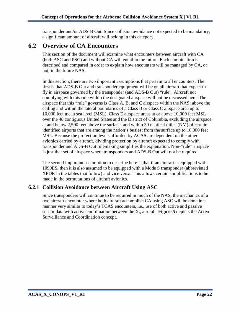
6.2.2 Collision Avoidance between Aircraft Using ASC and PSC In encounters between ACAS equipped aircraft using different means of surveillance and coordination, ASC and PSC, the encounter will be somewhat different than today. For one, the XP aircraft will make use of its own CA function, where there is no such CA capability for non-TCAS aircraft today. Figure 6 shows such an encounter between XA and a transponder-equipped XP.
Figure 6 - Encounter between an Aircraft with ASC-enabled ACAS and One with PSC-
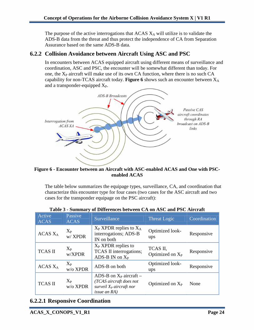
enabled ACAS The table below summarizes the equipage types, surveillance, CA, and coordination that characterize this encounter type for four cases (two cases for the ASC aircraft and two cases for the transponder equipage on the PSC aircraft):
Table 3 - Summary of Differences between CA on ASC and PSC Aircraft Active ACAS
Passive ACAS Surveillance Threat Logic Coordination
ACAS XA XP w/ XPDR
XP XPDR replies to XA interrogations; ADS-B IN on both
Optimized look-ups Responsive
TCAS II XP w/XPDR
XP XPDR replies to TCAS II interrogations; ADS-B IN on XP
TCAS II, Optimized on XP Responsive
ACAS XA XP w/o XPDR ADS-B on both Optimized look-
ups Responsive
TCAS II XP w/o XPDR
ADS-B on XP aircraft – (TCAS aircraft does not surveil XP aircraft nor issue an RA)
Optimized on XP None
6.2.2.1 Responsive Coordination

Concept of Operations for the Airborne Collision Avoidance System X | V1 R1
ACAS_X_CONOPS_V1_R1 Page 25
Responsive coordination is a new concept in coordination that is being developed in order to handle encounters between ASC and PSC aircraft with CA protection. It will direct the ACAS XP aircraft to select a RA with sense compatible to that chosen by the ASC CA. This applies in the first three rows in Table 3 – when ACAS XA and ACAS XP are in an encounter, or a TCAS II system encountering an aircraft with both a transponder and ACAS XP. In this case, when an ASC CA equipped aircraft (either ACAS XA or TCAS II) issues an RA against an ACAS XP threat, the XA equipped aircraft will (as for any RA) fill the appropriate Mode S transponder register(s) with RA information, so that the ADS-B RA Broadcast messages will be transmitted at the proper (increased) rate. When the RA is over, the appropriate transponder register(s) are cleared. The XP aircraft will receive the RA Broadcast and recognize that it (the XP aircraft) is the threat against which the ASC CA is issuing an RA. The surveillance processing on the XP aircraft will convert the up or down sense in the received ARA field into a resolution advisory complement, and use this to override any other costs used in the action selection, causing the threat logic to then issue a ‘Responsive RA,’ i.e., an RA that has a vertical sense compatible with that of the ASC CA equipped aircraft. Research is underway to determine the best types of ‘Responsive RA’ to be issued. When used onboard aircraft without transponders, ACAS XP will not issue an RA against TCAS II (coordination is not possible). The ACAS XP aircraft will receive TAs against the TCAS II aircraft. No CA protection is extended to aircraft today in this scenario, and this decision will avoid inducing collisions when no coordination is possible. XA-XP encounters will be discussed both from the perspective of the XA aircraft and the XP aircraft.
6.2.2.2 XA Aircraft Perspective In “rule” airspace, the XP aircraft will be equipped with a transponder, while in non-rule airspace a XP aircraft may not carry a transponder. If XP has a transponder, then from the XA perspective, the encounter works much like it does in encounters with transponder-equipped aircraft today. In an encounter with an XP aircraft without a transponder, XA would be capable of providing CA based on ADS-B, unlike current TCAS, which operates only against transponder-equipped aircraft. XA will be aware that it is encountering an XP aircraft without a transponder and would be able to use the ADS-B information to perform CA on the aircraft. This would be made possible through the use of validation of the ADS-B information using a passive ranging capability. Whether ACAS XA should issue an RA against a threat whose ADS-B data cannot be validated by active interrogation or passive ranging is currently an open question.
6.2.2.3 XP Aircraft Perspective This section focuses on PSC CA (ACAS XP) point of view. The XP aircraft may or may not be equipped with a transponder. The ACAS XP aircraft will surveil and track the ACAS XA equipped aircraft by receiving ADS-B broadcasts. Investigations are underway that will help define the need for, and

Concept of Operations for the Airborne Collision Avoidance System X | V1 R1
ACAS_X_CONOPS_V1_R1 Page 26
possibly the degree to which this ADS-B data needs to be validated by the ACAS XP aircraft. The XP aircraft will subordinate itself, using Responsive Coordination, and issue a compatible RA with whatever the aircraft that has ASC CA chooses for an RA. This is because the TCAS or ACAS XA uses additional data not available to the XP aircraft, and has a greater measure of independence than ACAS XP. However, in the case where the XP aircraft declares the aircraft with ASC CA a threat before the active system declares the XP aircraft a threat, research is underway to determine if the safest and most operationally suitable approach is to either have the aircraft with PSC CA wait until the aircraft with ASC CA chooses an RA that is received by the XP aircraft, or have the aircraft with PSC CA issue an RA and maneuver with the expectation that its own selected RA may be reversed if the active system issues a subsequent RA that conflicts.
6.2.3 Collision Avoidance between Aircraft Using ASC and NoCAS In an encounter with a transponder-equipped aircraft with no CA capability, the ACAS XA aircraft would be capable of performing CA in much the same way that TCAS operates against a transponder-equipped aircraft today, i.e. tracking and declaring alerts that protect both aircraft from collision. In an encounter with an aircraft equipped with ADS-B Out but no transponder (which would provide no CA today), ACAS XA would be capable of performing CA using PSC. Through its ADS-B receive capability, ACAS XA would be aware that it is encountering such an aircraft and would be able to use ADS-B information to provide CA protection.
6.2.4 Collision Avoidance between Aircraft Using PSC Since PSC is based on ADS-B information only, there is no distinction to be made between transponder-equipped and unequipped aircraft in this type of encounter, depicted in the Figure 7 below. CA would be provided via the validated ADS-B data received by both aircraft. It is unclear whether validation of the ADS-B data will be required for encounters between these aircraft. This will be determined through further research.
Figure 7 - Encounter between Two Aircraft with Passive Surveillance and Coordination
Currently, the approach to XP- XP coordination is to attempt to replicate, to the extent possible on a broadcast link, the active interrogation process (currently termed “active coordination emulation”). This approach would use a dedicated message format on ADS-

Concept of Operations for the Airborne Collision Avoidance System X | V1 R1
ACAS_X_CONOPS_V1_R1 Page 27
B that will mimic an addressed transmission by including the addresses of both the sending aircraft and the (intended) receiving aircraft. There will also be an indication that the message is intending to exchange resolution advisory information in a private XP-XP coordination exchange and should not be used by other receivers. As in XA-XA encounters, the two XP aircraft will then use their 24-bit addresses to determine which is the designated ‘master’ and ‘slave’ in the encounter. The first aircraft to select an RA sense prevails. In the case of simultaneous selection, the master prevails. Unlike XA-XA encounters, in XP-XP encounters, the slave must wait for a confirmation message from the master before displaying an RA to the pilot. This prevents the slave from having to reverse its displayed RA, an action deemed not desirable for ACAS XP aircraft. The reason for requiring the slave to wait for confirmation is that the inherent delay involved in using ADS-B for coordination makes the need to reverse more likely than it is for the crosslink coordination used in ACAS XA and TCAS II.
6.2.5 Collision Avoidance between Aircraft Using PSC and NoCAS An ACAS XP aircraft could perform CA as long as the aircraft has ADS-B Out, by making use of the ADS-B information provided by those aircraft. The PSC aircraft would be aware of the lack of CA capability on NoCAS aircraft, for example, so the CA logic for encounters with NoCAS aircraft would be no different than for encounters with other XP aircraft, other than no coordination through the ADS-B system would be attempted.
6.3 CA Protection in “Rule” and non-“Rule” Airspaces It is worthwhile to examine the protection, in the form of TA and RAs, extended over the CA categories. Table 4 is a summary of two-aircraft encounters that covers all valid permutations with TCAS, ACAS X, and aircraft not equipped with ACAS. Because “rule” airspace requires transponder and ADS-B equipage, the pairings are limited to cases where ownship has some level of ACAS (namely TCAS I, TCAS II, or ACAS XA/XP systems) and the intruder is surveilled both with transponder replies and with ADS-B messages. The gray shading indicates those combinations that are protected with current TCAS (those combinations of TCAS-TCAS protections for intruder-ownship). Table 5 that follows shows a corresponding set of pairings in non-“rule” airspace that will not require ADS-B or transponder equipage aboard aircraft. The pairings get slightly more complex, but there is a substantial extension of CA protection to encounters where none currently exists. Note that the aircraft equipped for “rule” encounters may have an encounter in non-“rule” airspace. The meanings of the terms used in the table are: • “TA” means only Traffic Advisories are issued. • “RA” means Resolution Advisories are issued in addition to Traffic Advisories. • “RESPONSIVE” follows the definition described in Section 6.2.2.1. • Note that “Mode A” is called out explicitly as a type of transponder (XPDR). It is
intended to represent those avionics installations that have a transponder, yet do not report altitude. The correct expression is "non-altitude reporting Mode C". The mechanism by which TCAS II issues TAs against these aircraft is making Mode C

Concept of Operations for the Airborne Collision Avoidance System X | V1 R1
ACAS_X_CONOPS_V1_R1 Page 28
interrogations and receiving an empty reply. This was reduced to “Mode A” for the sake of brevity.
• “ Mode C/S” indicates that the transponder can either be a Mode C or a Mode S type. • “ADS-B Out” indicates the type of ADS-B broadcasts assumed based on the equipage
(whether or not the aircraft has a transponder). • Aircraft equipped with TCAS II or ACAS XA implies 1090ES broadcasts as well. • Equipage with ACAS XP does not imply transponder equipage.
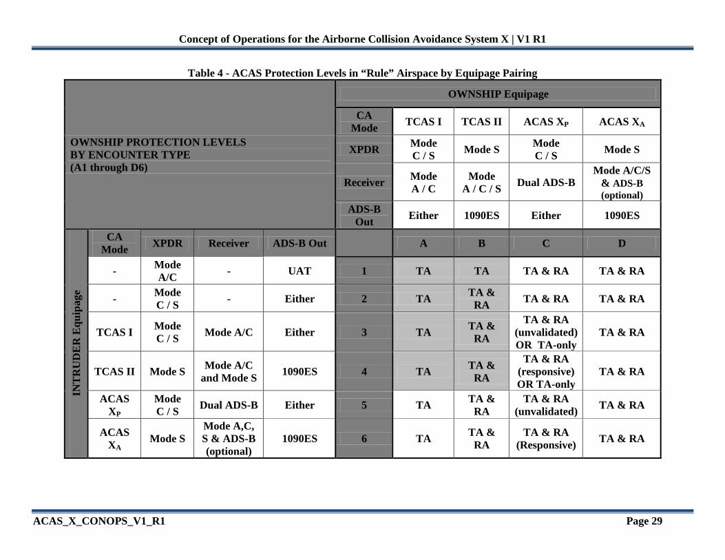
Concept of Operations for the Airborne Collision Avoidance System X | V1 R1
ACAS_X_CONOPS_V1_R1 Page 29
Table 4 - ACAS Protection Levels in “Rule” Airspace by Equipage Pairing
OWNSHIP PROTECTION LEVELS BY ENCOUNTER TYPE (A1 through D6)
OWNSHIP Equipage
CA Mode TCAS I TCAS II ACAS XP ACAS XA
XPDR Mode C / S Mode S Mode
C / S Mode S
Receiver Mode A / C
Mode A / C / S Dual ADS-B
Mode A/C/S & ADS-B (optional)
ADS-B Out Either 1090ES Either 1090ES
INT
RU
DE
R E
quip
age
CA Mode XPDR Receiver ADS-B Out A B C D
- Mode A/C - UAT 1 TA TA TA & RA TA & RA
- Mode C / S - Either 2 TA TA &
RA TA & RA TA & RA
TCAS I Mode C / S Mode A/C Either 3 TA TA &
RA
TA & RA (unvalidated) OR TA-only
TA & RA
TCAS II Mode S Mode A/C and Mode S 1090ES 4 TA TA &
RA
TA & RA (responsive) OR TA-only
TA & RA
ACAS XP
Mode C / S Dual ADS-B Either 5 TA TA &
RA TA & RA
(unvalidated) TA & RA
ACAS XA Mode S
Mode A,C, S & ADS-B (optional)
1090ES 6 TA TA & RA
TA & RA (Responsive) TA & RA
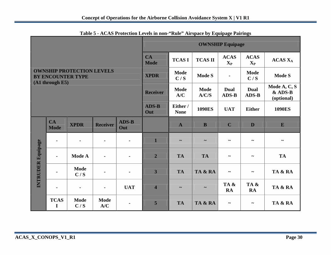
Concept of Operations for the Airborne Collision Avoidance System X | V1 R1
ACAS_X_CONOPS_V1_R1 Page 30
Table 5 - ACAS Protection Levels in non-“Rule” Airspace by Equipage Pairings
OWNSHIP PROTECTION LEVELS BY ENCOUNTER TYPE (A1 through E5)
OWNSHIP Equipage
CA Mode TCAS I TCAS II ACAS
XP ACAS
XP ACAS XA
XPDR Mode C / S Mode S - Mode
C / S Mode S
Receiver Mode A/C
Mode A/C/S
Dual ADS-B
Dual ADS-B
Mode A, C, S & ADS-B (optional)
ADS-B Out
Either / None 1090ES UAT Either 1090ES
INT
RU
DE
R E
quip
age
CA Mode XPDR Receiver ADS-B
Out A B C D E
- - - - 1 ~ ~ ~ ~ ~
- Mode A - - 2 TA TA ~ ~ TA
- Mode C / S - - 3 TA TA & RA ~ ~ TA & RA
- - - UAT 4 ~ ~ TA & RA
TA & RA TA & RA
TCAS I
Mode C / S
Mode A/C - 5 TA TA & RA ~ ~ TA & RA

Concept of Operations for the Airborne Collision Avoidance System X | V1 R1
ACAS_X_CONOPS_V1_R1 Page 31
7.0 PROPOSED SYSTEM This Section describes the proposed ACAS X system in more detail. Section 7.1 gives an overview of the system, using an ACAS XA system as an example to discuss the major pieces of the system. Section 7.2 discusses future CA. Section 7.3 summarizes the anticipated interfaces to external systems for both ACAS XA and ACAS XP. Section 7.4 wraps up the proposed system description by refining some of the system concepts discussed briefly earlier in the document.
7.1 Overview ACAS X is an avionics system, installed and operated on aircraft. A notional depiction of an ACAS XA system is shown in Figure .
ACAS X Processor Unit
Threat Resolution Module
Monitor
Surveillance and Tracking Module
Mode S Transponder
Radio Altimeter
Aircraft Discretes
Control Panel
Pressure Altitude
Traffic Display
RA Display
Aural Annunciator
4-Element Top
Antenna
Omni or 4-Element Bottom Antenna
or
Omni Top & Bottom Antennas
Figure 8 - Block Diagram of an Example of ACAS XA
This system implements both hardware and software, including the antenna system with 4-element arrays. The main differences between the depicted system and TCAS II reside inside the “ACAS X Processor Unit”, which implements the software that operates on the surveillance data and issues advisories. Inside this processor, the main software of ACAS X is shown – the Surveillance and Tracking Module (STM), the Threat Resolution Module (TRM), and the Monitoring function. Various inputs are required from the flight crew and the surveillance systems, and the outputs are indications and alerts to the flight

Concept of Operations for the Airborne Collision Avoidance System X | V1 R1
ACAS_X_CONOPS_V1_R1 Page 32
crew, both for advisory / situational awareness and for maneuvers that the flight crew should take to avoid collisions. The reason for changing from TCAS II to ACAS X is to provide more adaptability to new operations and separation modes, while improving safety, reducing the present alert rate and making it much easier to adapt the system to future changes. However, a design assumption imposed on the system is to make the changes as invisible to operators as possible. A useful analogue is the redesign of a model of car, where new parts are used, like improved motors or suspensions. Drivers do not have to drive differently, they can just take advantage of the new safety and reduced nuisance from the upgrade. To a flight crew, ACAS XA will behave as TCAS II does today, where it provides notification using a situation awareness traffic display, traffic and resolution advisory aural annunciations, and vertical rate guidance. During potential conflict situations where CA intervention is necessary, ACAS XA will provide resolution guidance with similar, but not identical, alert timings, durations, and sequences as TCAS II. The optimized safety logic is expected to reduce unnecessary alerts in non-conflict situations, so ACAS XA RAs may not be issued under the same conditions as legacy TCAS II. Furthermore, the set of RAs that will be issued are expected to be the same, or a reduced set that simplifies responses based on feedback from the operational community. There will be TAs issued when there is traffic that the flight crew should attempt to visually acquire and prepare for a possible RA. The modular design of ACAS X, with the STM and TRM as modules, helps reduce the cost and schedule of developing and maintaining this complex system. This modular approach makes it easier to read, write, debug, modify, and reuse programs. The current TCAS MOPS incorporates some aspects of modular design, but modularity was not the focus. Future upgrades to ACAS X are intended to be seamless through the use of this modularity as well (e.g. new logic tables will not affect the data passed to the TRM or new surveillance inputs will not necessarily require a new set of logic tables to be constructed). ACAS XP has more research planned to determine what sets of responses should be included and designed into the system, as this platform will target users that do not currently equip with TCAS and will have different training, experience, and aircraft performance than is assumed for TCAS II. Other operational aspects of the system will also be unaffected – the interaction with ATC, ground-based monitoring, interoperability with other systems, and the interoperability with other aircraft all will remain the same.
7.2 Future Avionics Equipage In accordance with the “ADS-B Out” rule, mentioned previously, aircraft will be required to be equipped with transponders as well as some ADS-B broadcast system. [16] It is also believed that aircraft that will not operate in rule-governed airspace may choose to voluntarily equip with ADS-B. It is assumed in this document that aircraft that equip with

Concept of Operations for the Airborne Collision Avoidance System X | V1 R1
ACAS_X_CONOPS_V1_R1 Page 33
1090ES will also carry transponders, regardless of where they fly. Aircraft that equip with UAT will also carry transponders if they fly in rule airspace, but may not have transponders in non-rule airspace. Table 6 below summarizes the most likely aircraft equipage categories that are expected to fly in rule or non-rule airspace. Note that the entries in this table do not account for the introduction of any new form of CA.
Table 6 - Aircraft Equipage in the 2020 NAS Prior to ACAS X
Aircraft Equipage Allowed Airspace Notes
TCAS (includes Mode S XPDR & 1090ES Out) Rule & non-rule Current TCAS Systems
Mode C/S XPDR + 1090ES Out Rule & non-rule Assumes 1090ES XPDR
Mode C/S XPDR + UAT Out Rule & non-rule
UAT Out (no XPDR) Non-rule only However, in order to cope with the challenges noted in Section 3.2.2 for NextGen, an improved CA function incorporating optimized logic and ADS-B Receive will be needed. Table 7 summarizes aircraft equipage categories that will exist after the implementation of ACAS X, in addition to those listed in Table 6 (which will all still be operating in the airspace, but will not receive any direct benefits conveyed by equipping with ACAS X).
Table 7 - Additional Aircraft Equipage in 2020 NAS Due to ACAS X Aircraft Equipage1 Allowed Airspace ACAS XA (includes Mode S XPDR, 1090ES Out, optional ADS-B IN) Rule & non-rule
ACAS XP (includes Mode C/S XPDR, 1090ES Out/In, and UAT In 2 Rule & non-rule
ACAS XP (includes Mode C/S XPDR, 1090ES In, and UAT Out/In Rule & non-rule
ACAS XP (no XPDR, 1090ES In, UAT Out/In) Non-rule only
Notes: 1- ACAS XA does not require ADS-B reception capability. ACAS XP requires a dual-receive ADS-B capability to properly coordinate with all possible rule-compliant installations of ADS-B. 2 - This implicitly assumes 1090ES Out is transponder based.
As stated in the beginning of this document, ACAS XA is the version of ACAS X that is capable of active surveillance using its TCAS interrogator, while ACAS XP is a passive version of ACAS X, using only ADS-B information to provide CA. All aircraft that currently carry TCAS II will be candidates for the active version of ACAS X in the future (ACAS XA), i.e., they will be capable of active interrogation of

Concept of Operations for the Airborne Collision Avoidance System X | V1 R1
ACAS_X_CONOPS_V1_R1 Page 34
aircraft in addition to being equipped with plug and play surveillance, optimized threat logic, and ADS-B Receive. Retaining the ability to interrogate nearby aircraft is extremely important for three reasons: (1) backwards compatibility with current TCAS, (2) validation of ADS-B data (which essentially allows satisfying the requirement that the aircraft CA function be independent of the separation assurance function), and (3) providing surveillance in the absence of ADS-B data. Aircraft that currently are not required to carry TCAS II will be candidates for the passive version of ACAS X in the future, i.e., they will be equipped with ADS-B Out and will carry a transponder in rule airspace, but will not be capable of active interrogation of aircraft. In order to provide the passive CA function, they will be equipped with both the optimized threat logic and dual-link ADS-B receiver systems.
7.3 Interfaces to External Systems The expected and possible external systems and data that ACAS XA will interface with are: • Mode S transponder (and the altimeter by way of the transponder) • Control Panel (to select the operating mode) (may be combined with other control
panel inputs, such as a Mode S control panel) • Discrete Input systems (that set aircraft operating characteristics) • Radio Altimeter • Any ADS-B data already decoded in an external system and passed on to ACAS X • Suppression pulse data from co-site ownship transmitting systems • (Potentially) cross-link data from 1030/1090 MHz systems to enable specific
applications • Pilot inputs into Cockpit Display of Traffic Information or some yet-to-be-defined
ACAS X interface to select targets Interfaces with ACAS XP and ACAS XO have yet to be fully defined, although they are a subset of the interfaces above.
7.4 System Concepts This section provides an overview of some more ACAS X specific characteristics.
7.4.1 Surveillance & Tracking Module One of the fundamental design differences that will exist between TCAS II and ACAS X is the placement of the internal interface between the surveillance function and the threat resolution logic. ACAS X will require all tracking algorithms to be contained within the STM. The threat logic housed in the TRM will no longer accept measurements as input, but rather a target’s tracked state information. This shift in tracking functionality effectively decouples the TRM from the STM and establishes a new paradigm for the design of a CAS: ACAS X will allow a single optimized threat logic to be compatible with any surveillance source (e.g. beacon interrogations, ADS-B, electro-optical, primary radar, etc.) or combination of sources that meet minimum performance requirements.

Concept of Operations for the Airborne Collision Avoidance System X | V1 R1
ACAS_X_CONOPS_V1_R1 Page 35
To take advantage of this aspect of ACAS X, the STM must be designed to handle multiple surveillance sources to accommodate whatever surveillance hardware is installed on other aircraft. Doing so implements one component of the “Plug and Play Surveillance” concept, which is:
All ACAS X surveillance sources will be received by (i.e., plugged into) a single version of the STM. The STM will automatically recognize each surveillance message that has been received, process it, and use it to track the associated intruder without the need for manual configuration or additional programming.
This means that the STM will dynamically ‘plug’ in all approved sources of surveillance data that can contribute to a target’s track. As an example, assume ACAS X has the ability to transmit beacon interrogations, receive UAT ADS-B data and is equipped with an electro-optical sensor. If a target aircraft were to have a transponder, ACAS X would interrogate the target aircraft. If that target aircraft did not have a transponder but broadcasted UAT data, ACAS X would receive and process the UAT data. If the target aircraft had both a transponder and broadcasted UAT data, ACAS X would interrogate the target aircraft and receive and process both its replies and UAT data. And regardless of the avionics installed on the target aircraft, provided the aircraft were in visible range, ACAS X would use the electro-optical sensor on the target.
Figure 9 - Overview of Initial “Plug and Play Surveillance” Design
Each class of ACAS X (ACAS XA, ACAS XP, ACAS XO, or future versions for UAS) will utilize the concept of “Plug and Play Surveillance” based on the sensing capability

Concept of Operations for the Airborne Collision Avoidance System X | V1 R1
ACAS_X_CONOPS_V1_R1 Page 36
provided by the hardware installed on the ACAS X aircraft. The initial design of ACAS X surveillance will focus on three classes: • XA, which has the ability to actively transmit beacon interrogations, • XP, which will rely solely on passive ADS-B data, and • XO, which will allow ACAS X to be more compatible with specific operations. There will be one standard interface that will exist between the ACAS X STM and TRM. Defining this one standard interface implements the second component of “Plug and Play Surveillance” which is:
Any ACAS X TRM will connect and work seamlessly with a single version of the STM.
This aspect of “Plug and Play Surveillance” will allow for the design of one STM to be compatible with the optimized threat logic for ACAS XA, XP and XO. For “Plug and Play Surveillance” to be an effective solution, the STM must be capable of providing the TRM with the uncertainty associated with the position and velocity of the intruders. As a result, the STM will provide a distribution over each parameter rather than a scalar value. The TRM will use this distribution information to choose the optimal action for each target aircraft given the uncertainty provided.
7.4.2 Centralized Tracking ACAS X systems will centralize tracking for the system. The expectation is that the means to achieve this will involve the use of a specialized tracker/filter. These tracking filters excel at combining inputs from various sources, providing a best estimate of the position and velocity of a target, and accounting for uncertainty in the input measurements and output of the filter. A set of estimated states and associated weights (probabilities that represent the uncertainty of these states) will be passed to the TRM.
7.4.3 Optimized Threat Logic Concepts The concepts used in optimizing the threat logic were developed over the course of several years by MIT Lincoln Laboratory.[20,21,22] The optimized threat logic is produced “offline”; that is, the optimization is done on computer systems well before ACAS X is installed on the aircraft, notionally depicted in Figure . The tables encode the optimal action to choose, given a set of state variables. The challenge of the avionics system that stores these logic tables is to as accurately as possible, estimate these state variables, through improved surveillance, tracking, and estimation techniques that account for inaccuracies. A complete accounting for the safety and operational benefits of this optimized approach is both beyond the scope of this Concept of Operations, but also premature, as the final results of the design are yet to be complete.

Concept of Operations for the Airborne Collision Avoidance System X | V1 R1
ACAS_X_CONOPS_V1_R1 Page 37
SurveilTargets
Track Targets
Estimate State
Select Action
Track Data
State Distribution
Notify Pilot
Advisory
Logic Tables
Onboard ACAS X System
Offline Logic Table Production
Encounter Model
Cost Tables
Model Discretization
Optimization
Discrete Model
Figure 10 - Depiction of the “Offline” Processes and Onboard Functions with Logic Tables
7.4.4 Display and Annunciation The interactions flight crews currently conduct with TCAS II systems are expected to remain unchanged or largely unchanged with the ACAS X systems. The Resolution Advisories used are the same set as those included in TCAS 7.1. However, there are several items that are expected to be slightly different, with impacts to be determined: • The manner of issuing TAs is expected to be triggered by different criteria that more
directly map to the functions that TA supports. The functions of TAs are (1) to facilitate visual acquisition, and (2) to prompt the pilot mentally in order to facilitate quicker response to an eventual RA, if one is issued. Research is being conducted to make sure the operational benefits of issuing TAs are still fulfilled, while fitting these alerts within the framework of ACAS X systems.
• The interaction with systems that receive and process ADS-B data, called Aircraft Surveillance Applications Systems (ASAS), may change some pilot procedures. ASAS allows pilots to select aircraft for special applications, like paired approaches, which may use reduced separation rules, which in turn, might cause unnecessary high rates of RAs. To address this, there is expected to be a complementary function on ACAS X systems that allows the selection of targets. This selection will allow the system to use different logic tables or selection algorithms to issue RAs.

Concept of Operations for the Airborne Collision Avoidance System X | V1 R1
ACAS_X_CONOPS_V1_R1 Page 38
• Currently, TCAS systems classify traffic into four categories: (1) threats, against whom RAs are issued, (2) potential threats, against whom TAs are issued, (3) proximate targets, which are those aircraft within 6 NM and 1,200 feet of ownship that are not intruders or threats, and (4) other traffic, which is all other aircraft “in track” of the surveillance system. Because the approach to TAs may be changed, proximate and other traffic might also have a slightly different definition under ACAS X. Research may also be conducted to determine the use and operational benefit of proximate targets, and attempt to maximize this benefit through a re-definition.
• Finally, new systems providing data to the cockpit, such as ADS-B enabled Airborne Separation Assurance Systems (ASAS), may duplicate some of the functionality of the traffic display for ACAS X. Some manner of interoperability between these two systems will be provided for on aircraft that host both systems, so that the pilot is not given duplicate indications for proximate traffic, or other low-level alerting. It is expected that RAs will remain unchanged and will take priority on any situational display.
7.5 Constraints and Key Assumptions This section summarizes several important assumptions that are so embedded in the concept of ACAS X put forth here, that, if any of these were to change, a revision of these ConOps would be necessary. These are: • Explicit coordination – a constraint levied on ACAS X is that it would perform
explicit coordination (as TCAS II does currently) where at least one aircraft must declare its RA status to the other aircraft. The alternative to this is a system where each aircraft decides independently its preferred advisory.
• Optimized Action Tables – a fundamental design principle in ACAS X is the selection of actions and advisories using a simple table look-up using state data inputs, rather than performing real-time computations of complex aircraft trajectories.
• Plug and Play Surveillance – the surveillance system in the ACAS X concept can
have active TCAS surveillance, ADS-B data, other yet-to-be-defined sensors, or any combination of these, and the data parameters passed to the “logic” tables will be the same. This allows future upgrades to the logic tables without having to go back and make hardware and software upgrades to the front-end of ACAS X.

Concept of Operations for the Airborne Collision Avoidance System X | V1 R1
ACAS_X_CONOPS_V1_R1 Page 39
8.0 Verification and Validation For systems that have safety-of-life consequences such as ACAS X, the verification and validation of the system is critical. Verification is the assurance that the system that is built conforms to the requirements and design. Validation is the assurance that the system that is built conforms to the operational goals of the system. In simple terms, verification makes sure you built the thing correctly, and validation makes sure you built the right thing. This section lays out the proposed approach, at a high level, for four aspects of the verification and validation efforts: 1. How a specific implementation of ACAS X is verified as meeting system
requirements 2. How the safety of ACAS X will be validated 3. How it will be demonstrated that ACAS X is operationally suitable for flight crews 4. How a change proposal (CP) to the established ACAS X system is expected to be
implemented
8.1 System Verification The approach to logic development being pursued for ACAS X differs greatly from TCAS II. The TCAS II cycle of pseudocode development, simulation, evaluation of performance metrics (e.g. risk ratio), and iteration is expected to be replaced with a more linear process. Performance metrics and an encounter model are used to optimize a set of logic tables, which are then evaluated. Various costs metrics and upfront criteria are adjusted such that the overall system achieves the desired behavior.
Figure 2 - Depiction of Legacy TCAS and ACAS X Development Approach
As stated above, the purpose of verification is proving that the ACAS X is implemented correctly, matching the specified requirements. In past TCAS implementations, avionics

Concept of Operations for the Airborne Collision Avoidance System X | V1 R1
ACAS_X_CONOPS_V1_R1 Page 40
manufacturers have always been responsible for verification of their specific installations. They have relied upon tests in DO-185B, which include overall system tests as well as specific tests for surveillance and CAS, the latter of which included the TCAS Simulation Interactive Module (TSIM) test suite. TCAS II logic is documented both in complex pseudocode and statechart format. TSIM implements both formats of this logic. This dual specification approach was adopted because formal verification was not possible on pseudocode, which does not have the mathematical foundation needed to prove the correctness of an implementation. Therefore, a statechart format of the TCAS II logic was reverse engineered from the pseudocode. This format was intended to enumerate all possible states of the CA system, enabling the development of test cases that attempt to cover these different states. Requirements are verified by testing whether outputs (e.g. displayed advisories, internal logic states) are as specified across both formats [19]. Test files are provided electronically to the manufacturers. Testing procedures and additional details can be found in the CAS Test Procedures section (2.4.2.2) of the TCAS MOPS.[14] Despite the promise of statecharts, the format was never applied in such a way as to rigorously prove the correctness of a logic implementation. The 300 TSIM test cases, while providing state coverage, never provided “complete path” coverage which would verify that all logic paths possible in TCAS had been exercised. For ACAS X, logic look-up tables, along with a pseudocode representation of the STM and TRM algorithms responsible for tracking, developing state estimates from those tracks, and using those estimates to index into the look-up tables will be provided. Since the majority of the ACAS X logic itself has now been encoded in the look-up tables, it may be harder to distinguish between low-level versus high-level requirements. The verification strategy for ACAS X, summarized in Figure 3, will leverage software best practices and will capitalize on specific improvement brought by ACAS X. For instance, since most of the TCAS II complexity has been converted to a tabular format in ACAS X, thorough integrity tests confirming uncorrupted content is loaded and maintained in the look-up tables are crucial. Also, the ACAS X online logic has a smaller footprint and significantly less branching than the TCAS II logic. Code coverage tests will demonstrate that the ACAS X logic has been thoroughly exercised. In TCAS II, each line of pseudocode was considered a requirement. For ACAS X, showing that all lines of code have been executed and tested will support verification. In addition, a suite of unit tests will be introduced that evaluates the individual ACAS X online logical modules that perform the functions of Estimate State and sub-modules and verifies them in a mathematically rigorous manner. Also, a larger set of TSIM-like test cases (that is still within the ability of a real-time system to execute in a timely manner) will be developed to test the end-to-end system. Finally, it is noted that since an installation cannot test all possible input conditions, it is difficult to prove the verification of an installation. However, ACAS X significantly reduces the overall amount of avionics code required for an implementation, minimizing

Concept of Operations for the Airborne Collision Avoidance System X | V1 R1
ACAS_X_CONOPS_V1_R1 Page 41
the opportunity for errors. The full set of plans will be formalized into a Verification Plan as the system concept becomes more crystallized.
Figure 3 - Overview of ACAS X Verification Strategy
8.2 Safety Validation The safety validation is the most critical component of any effort in changing between certified ACAS designs. Changes must maintain the established level of safety enjoyed by TCAS II systems. In addition, many of the heuristic tests designed into TCAS II, which ACAS X intentionally casts off in favor of the optimized approach, must be considered in the ACAS X design. This requires specific tests to ensure that safety and performance in those specific cases is not compromised. The bulk of safety validation will use established processes that have been used historically in TCAS development. These include encounter modeling and the use of Monte Carlo simulations to evaluate the safety of the system using models agreed to by the TCAS community. The encounters themselves are generated based on situations observed empirically in monitored data, but can be tailored to incorporate classic problems seen in TCAS encounters and other interesting cases that stress CA. An example of this would be low-altitude encounters, where RAs are inhibited for a variety of operational reasons, which is not effectively evaluated using the large-scale modeling tools. Of particular importance is the demonstration that ACAS X, in its various forms, is interoperable with legacy versions of TCAS II and is compatible with ADS-B and transponder variants as well. This effort will entail several aspects: showing that this interoperability holds in the large-scale models, deriving special cases that may be more stressful to this interoperability (as compared to the large-scale randomly selected encounters), and demonstrating this interoperability in implemented systems. Furthermore, ACAS X must demonstrate that its safety benefits are robust to a variety of conditions that are observed in the real world. The assumptions in the models should be tweaked and varied in appropriate ways to determine the response of the system. Some aspects that are planned to be evaluated are different encounter models, such as a

Concept of Operations for the Airborne Collision Avoidance System X | V1 R1
ACAS_X_CONOPS_V1_R1 Page 42
European airspace model or models that feature more GA-like traffic encounters. In addition, the assumption of pilot response is important in modeling, but non-standard pilot responses will be observed in practice, so ACAS X should be able to respond appropriately (although no collision avoidance system can overcome worst-case pilot responses). Finally, some evaluation of robustness with respect to different cost models should be shown, in order to ensure that small changes in the costs do not greatly change the safety of the system. This may be significant in the future if any changes to the cost model are considered.
8.3 Operational Suitability In order to be successful in any real operational environment, ACAS X must provide the desired level of safety while providing alerts that are acceptable to pilots, air traffic controllers, and other industry stakeholders such as airline operators. Operational suitability assessment and optimization is an important aspect of the TRM logic development to ensure that the acceptable balance of safety benefit and operational utility is achieved. For example, maximum safety benefit may be attained at the cost of significant deviations from intended flight paths or excessive alerting. Conversely, minimizing alerting may result in an ineffective safety system. Optimization of the safety logic to behave acceptably both from a safety and operational perspective requires (1) a well-defined safety requirement (e.g. a target level of safety) and (2) a comprehensive definition of desirable behavior under a variety of scenarios that largely reflect either current or proposed operations in the airspace. The trade-off between these safety and operational suitability objectives must also be understood and accepted. Operational suitability analyses will be conducted throughout the system development process. During this process, adjustments to the cost function or other system components to achieve the objective of minimal unnecessary alerts must be balanced against the impact on the safety benefit under specific operational scenarios. The first step in operational suitability analysis is to clearly define the relevant scenarios, operations, and procedures with corresponding TRM logic success metrics. During the initial operational suitability analysis, these scenarios will be defined and tested based on knowledge of current air traffic management procedures and will use supporting data from the current airspace environment. Other scenarios may be added during the development process to assess the anticipated performance of the TRM in new future environments or current procedures with additional surveillance capabilities. The second step is prioritizing these scenarios based on frequency of occurrence, importance to the user community, and probability and severity of interaction between these scenarios and alerts. The high level goal of this prioritization is to identify the normal, safe aircraft encounters under which alerts may result in potential airspace inefficiencies, increased workload, and higher operating costs from the perspective of ATC, pilots, and operators. The third step is to test the logic in the dynamic range of each defined scenario outlined in step 2 and compare the behavior of the TRM logic with the success metrics defined in step one. These success metrics will include measures of user acceptance and safety. If the safety and utility balance is not centered around the successful operating point as defined in step 1, changes within the TRM and additional iterations of step 3 may be

Concept of Operations for the Airborne Collision Avoidance System X | V1 R1
ACAS_X_CONOPS_V1_R1 Page 43
necessary. Only when the success metrics have been met to an acceptable level will the system meet the baseline operational suitability requirements. The second phase of the operational suitability evaluation is soliciting user feedback to ensure the technical system performance that has met the pre-defined success metrics is in line with the expectations of the human(s) in the loop. Pilot acceptance of the behavior of ACAS X is crucial in preparing it for live, operational testing. Ensuring that the system provides guidance that pilots understand, trust, and deem appropriate for a wide range of scenarios is a key phase of operational suitability testing. In this phase, representatives of the pilot and ATC community will be asked to evaluate the performance of ACAS X under the most important scenarios and encounter types to provide feedback regarding its acceptability based on their experience and domain expertise. This feedback process is intended to identify and help resolve operational suitability issues such as initial timing of the alerts, durations, alert types and sequences, etc. These evaluations will be performed through assessment of specific encounters in various presentation formats, focus groups, and Human-in-the-Loop simulations of varying degrees of fidelity. Like the process described in step 1, any undesirable behavior or performance will be addressed through appropriate changes to the TRM. Successful operational suitability optimization will require a well-defined operating environment and safety level expectations, and substantial cooperation from all parties representing the spectrum of the overall system stakeholders (engineers, pilots, ATC, operators, regulators, etc.). There should be consensus that in many scenarios safety will largely vary inversely with the level of perceived unnecessary alerts. Some unnecessary alerts and incurred operating costs will result from using the system. However, the main goal is that the negative costs related to low-level interference with normal, safe procedures will be insignificant compared to the industry detriment of a mid-air collision. Operational suitability assessment and optimization therefore is an integral but collaborative piece of the TRM logic development to ensure that the acceptable balance of safety benefit and utility is achieved.
8.4 Implementing Change in the Deployed Systems The process by which requirements changes are made to the TCAS MOPS is started with the submission of a Change Proposal (CP) document to the standards bodies involved (e.g. RTCA and EUROCAE). For TCAS II systems, this CP might include proposed changes to the pseudocode, which would have to be translated into the companion statechart format. For the Verification of the change, iterative cycles of creating test scenarios for TSIM would ensue, where the coverage of all possible state transitions, as well as the effect on past test scenarios, was evaluated. In addition, safety and operational validation work would run parallel (or precede the Verification to some degree) in order to determine that this change was worthwhile (as opposed to the Verification question of whether the requirements were still being met). With ACAS X systems, there will still need to be the same level of Validation performed for any change proposed to the baseline system. However, Verification activities should be greatly simplified, as noted in the Section above. For any CP submitted, there will

Concept of Operations for the Airborne Collision Avoidance System X | V1 R1
ACAS_X_CONOPS_V1_R1 Page 44
need to be a classification structure of a kind that has not been necessary previously because so much of the decision logic is embedded in the look-up tables. At a minimum, two groups of CPs are those that only change the cost values encoded in the look-up tables, and those that change the online processing and functionality of ACAS X. For the former, if Validation (safety and operational) proves these are correct changes, then presumably no change need be made in the Verification process, and all the tests can be rerun to verify the same adherence to the requirements. However, if the pseudocode or other functionality changes, it may be necessary to evaluate the changes with additional or modified tests to Verify the system.

Concept of Operations for the Airborne Collision Avoidance System X | V1 R1
ACAS_X_CONOPS_V1_R1 Page 45
9.0 ACRONYMS 1090ES 1090 MHz Extended Squitter ACAS Airborne Collision Avoidance System ACAS XA ACAS X – Active ACAS XP ACAS X – Passive ACAS XO ACAS X – NextGen Ops ADS-B Automatic Dependent Surveillance – Broadcast ANSP Air Navigation Service Provider ASAS Airborne Separation Assurance System ASC Active Surveillance and Coordination ATC Air Traffic Control CA / CAS Collision Avoidance (System) CM Configuration Management CMS Conflict Management System ConOps Concept of Operations CP Change Proposal CPA Point of Closest Approach CSPO Closely Spaced Parallel Approach FAA Federal Aviation Administration GA General Aviation GNSS Global Navigation Satellite System ICAO International Civil Aviation Organization IFR Instrument Flight Rules MOPS Minimum Operational Performance Standards MSL Mean (height above) Sea Level NAS National Airspace System NextGen Next Generation Air Transportation System NM Nautical Mile NMAC Near Mid-Air Collision PO Program Office PSC Passive Surveillance and Coordination RA Resolution Advisory SA / SAS Separation Assurance (System) SCM / SCMS Strategic Conflict Management (System) STM Surveillance and Tracking Module TA Traffic Advisory TCAS Traffic Alert and Collision Avoidance System

Concept of Operations for the Airborne Collision Avoidance System X | V1 R1
ACAS_X_CONOPS_V1_R1 Page 46
TRM Threat Resolution Module TSIM TCAS Simulation Interactive Module UAT Universal Access Transceiver UAS Unmanned Aerial System VFR Visual Flight Rules XPDR Transponder

Concept of Operations for the Airborne Collision Avoidance System X | V1 R1
ACAS_X_CONOPS_V1_R1 Page 47
10.0 REFERENCES [1] ICAO Document 9854 “Global Air Traffic Management Operational Concept:”
First Edition 2005 [2] Zeitlin, A. D. (ed.), “Recommendations for Future Collision Avoidance Systems,”
Special Committee SC-147, RTCA, Inc., November 2011 [3] M. J. Kochenderfer, J. P. Chryssanthacopoulos, and R. E. Weibel, “A new
approach for developing safer collision avoidance systems,” in USA/Europe Air Traffic Management Research and Development Seminar, Berlin, Germany, 2011.
[4] Bachman, Lawrence, “Future Collision Avoidance”, Revision 3 [5] Javits, Leo; Olson, Wesley A.; Olszta, Jessica E.; “TCAS Operational
Performance Assessment (TOPA) Report #6”, MIT Lincoln Laboratory, Lexington, MA, January 1 2011
[6] “Next Generation Air Transportation System Integrated Plan”, Joint Program
Development Office, December 12 2004 [7] “Concept of Operations for the Next Generation Air Transportation System”,
Version 2.0, Joint Planning and Development Office, June 13 2007 [8] “FAA Aviation Safety: ADS-B Frequently Asked Questions”, Federal Aviation
Administration [9] “Airworthiness Approval of Automatic Dependent Surveillance – Broadcast
(ADS-B) Out Systems”, Advisory Circular No. 20-165, Federal Aviation Administration, May 21, 2010
[10] Drumm, Ann C.; Kuchar, James K.; “The Traffic Alert and Collision Avoidance
System”, MIT Lincoln Laboratory Journal, Volume 16, Number 2, 2007 [11] J. P. Chryssanthacopoulos and M. J. Kochenderfer, "Analysis of Open-loop and
Closed-loop Planning for Aircraft Collision Avoidance," in IEEE International Conference on Intelligent Transportation Systems, Washington, D.C., 2011.
[12] J. P. Chryssanthacopoulos and M. J. Kochenderfer, "Hazard Alerting Based on
Probabilistic Models," in AIAA Guidance, Navigation, and Control Conference, Portland, Oregon, 2011.
[13] Yang, L. C. and Kuchar, J. K., “Prototype conflict alerting system for free flight,"
Journal of Guidance, Control, and Dynamics, Vol. 20, No. 4, July-Aug. 1997, pp. 768-773.

Concept of Operations for the Airborne Collision Avoidance System X | V1 R1
ACAS_X_CONOPS_V1_R1 Page 48
[14] “Minimum Operational Performance Standards for Traffic Alert and Collision
Avoidance System II (TCAS II) [DO-185B]”, Volume I, RTCA SC-147, June, 2008
[15] “Annual Review of Aircraft Accident Data – U.S. General Aviation, Calendar
Year 2006 [NTSB/ARG-10/01, PB2010-114500]”, National Transportation Safety Board, July, 2010
[16] “Automatic Dependent Surveillance–Broadcast (ADS–B) Out Performance
Requirements to Support Air Traffic Control (ATC) Service (Final rule)”, Department of Transportation, Federal Aviation Administration, 14 CFR Part 91, Docket No. FAA–2007–29305; Amdt. No. 91-314,
[17] “Minimum Operational Performance Standards (MOPS) for Traffic Alert and
Collision Avoidance System II (TCAS II) Hybrid Surveillance [DO-300].”, RTCA SC-147, December, 2006
[18] “TCAS Compatibility with ADS-B 3NM En Route Separation – TCAS
Horizontal Miss Distance Filter and Potential Logic Modifications”, JHU/APL Report AI-11-019, March 2011
[19] Men, H.; Sidel, Z.; “Updating the Collision Avoidance Subsystem Verification
Test Suite for TCAS II Version 7.1”, 2008