Embed Size (px)
Citation preview

U.S. Department of the Interior Bureau of Reclamation Technical Service Center Hydraulic Investigations and Laboratory Services Group Denver, Colorado May 2011
Hydraulic Laboratory Technical Memorandum PAP-1035
Concept Level Design of a Fish-Friendly Pump System Tracy Fish Collection Facility


1
Abstract Newer methods of operation are needed at the Tracy Fish Collection Facility to meet fish salvage criteria. The existing facility is no longer capable of meeting hydraulic design criteria due to adverse flow conditions and water levels in the primary channel (primary). The secondary channel (secondary) depends on energy head (difference in water surface elevations) from the primary channel to drive the bypass flows necessary for optimum fish salvage. Current performance of the secondary suffers due to frequent periods of low water levels in the primary channel. WEMCO-Hidrostal fish-friendly pumps were investigated as a method to produce additional head needed during periods of low water levels to allow the secondary to meet performance standards. Various fish pump system designs were considered, focusing on hydraulic criteria and space limitations at the facility. One concept level design was determined to be feasible and is recommended for further investigation and design.
Introduction The Tracy Fish Collection Facility (TFCF) is a fish salvage facility located at the head of the Delta-Mendota Canal in the San-Joaquin Delta, California. It was built in the 1950’s with the purpose of preventing fish from entering the Delta-Mendota Canal which leads to the Tracy (C.W. Bill Jones) pumping plant. Fish drawn towards the pumping plant are collected at the TFCF, loaded into large haul trucks and transported to the Sacramento River. The fish are guided from the primary channel into underground bypass pipes that lead to a secondary channel and then to large circular holding tanks (Figure 1). The existing facility was designed to use gravity to provide the necessary flow from the primary channel to the secondary channel for effective fish collection.

2
Primary Channel
Bypass Pipes (4)
Secondary Channel
Holding Tanks (4)
Figure 1 – Existing Tracy Fish Collection Facility site
Over the last few decades, additional facilities have been added to the San-Joaquin Delta. In addition to these facilities, operational changes at the Tracy pumping plant and tidal fluctuations cause water levels to vary in the primary channel. Frequent periods of extremely low water levels in the primary channel make current facility operation difficult. Often fish salvage criteria (flow depth, velocity, and bypass ratio standards) are impossible to achieve in the secondary channel. To consistently meet these hydraulic criteria, additional energy head is required to provide adequate flow to the secondary channel.
In April of 2010 TFCF personnel asked the Technical Service Center (TSC) to investigate the feasibility of using Wemco-Hidrostal pumps as a retrofit to transport fish to the secondary. These “fish-friendly” pumps are an attractive option for the TFCF because they are capable of providing consistent flow during periods of low water levels and enhancing fish salvage without modifying or replacing a major portion of the existing facility infrastructure and operation.
The primary objective of this study was to determine the feasibility of using fish-friendly pumps to “enhance the efficiency of screening, fish survival, and reduction of predation within the secondary channel structure” (NMFS, 2009). Hydraulic conditions and space limitations were the main focus in developing the design alternatives. Existing hydraulic conditions in the secondary channel were first determined for comparison to the projected conditions for each design

concept. Appraisal level cost estimates for each alternative were also determined. Although various preliminary fish pump system concepts were developed as part of this study (Appendix C), only two alternatives are presented in this report.
Existing Conditions Existing hydraulic conditions were analyzed to assess the need to modify operation of the secondary channel. Depth and velocity data that were collected at the TFCF from February 2006 to April 2010 were analyzed. Velocities and bypass ratios (ratio of bypass velocity to channel velocity) were measured by TFCF personnel using ultrasonic pipe flow meters and other instrumentation. Table 1 summarizes the existing conditions in comparison to operational standards that have been established for seasonal time periods at this facility (NMFS, 2009 and CSWRCB, 1978).
The data show large variance for the secondary channel, which also affects depths in the holding tanks. The average values shown may be deceiving from an operational standpoint because each parameter is constantly changing. While some of the variance may have been intentionally controlled (predator removal, research, etc.) the majority was caused by fluctuating water levels in the primary channel.
Table 1 – Current hydraulic operating conditions of secondary channel
Parameter Period Standard- - - Max Min Avg.
Nov - May 3.0 6.76 0.25 2.85Feb - May 3.0 - 3.5 6.76 0.25 2.85
Existing Hydraulic Conditions - Secondary Channel
Velocity
Results
May - June 1.0 4.77 0.51 2.28June - August ≤ 2.5, 1.5 preferred 6.51 0.25 1.89Sept. - Oct. 1.0 5.73 0.26 2.17Nov - May > 1.0 4.96 0.11 1.33May - June > 1.0 4.30 0.70 1.58June - August > 1.0 4.97 0.53 1.87Sept. - Oct. > 1.0 4.66 0.54 1.60Nov - May - 10.80 1.20 5.78May - June - 10.30 4.00 6.77June - August - 10.41 2.20 6.31Sept. - Oct. - 8.90 3.00 5.87
Decision 1485NFMS 2009 B.O.
Flow Depth (ft )
Bypass Ratio (BR)
(fps )
3
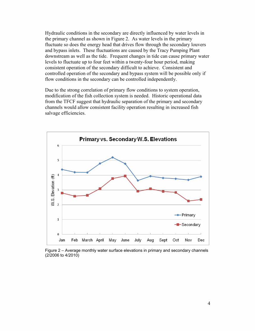
Hydraulic conditions in the secondary are directly influenced by water levels in the primary channel as shown in Figure 2. As water levels in the primary fluctuate so does the energy head that drives flow through the secondary louvers and bypass inlets. These fluctuations are caused by the Tracy Pumping Plant downstream as well as the tide. Frequent changes in tide can cause primary water levels to fluctuate up to four feet within a twenty-four hour period, making consistent operation of the secondary difficult to achieve. Consistent and controlled operation of the secondary and bypass system will be possible only if flow conditions in the secondary can be controlled independently.
Due to the strong correlation of primary flow conditions to system operation, modification of the fish collection system is needed. Historic operational data from the TFCF suggest that hydraulic separation of the primary and secondary channels would allow consistent facility operation resulting in increased fish salvage efficiencies.
Figure 2 – Average monthly water surface elevations in primary and secondary channels (2/2006 to 4/2010)
4
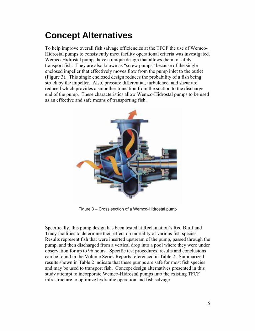
Concept Alternatives To help improve overall fish salvage efficiencies at the TFCF the use of Wemco-Hidrostal pumps to consistently meet facility operational criteria was investigated. Wemco-Hidrostal pumps have a unique design that allows them to safely transport fish. They are also known as “screw pumps” because of the single enclosed impeller that effectively moves flow from the pump inlet to the outlet (Figure 3). This single enclosed design reduces the probability of a fish being struck by the impeller. Also, pressure differential, turbulence, and shear are reduced which provides a smoother transition from the suction to the discharge end of the pump. These characteristics allow Wemco-Hidrostal pumps to be used as an effective and safe means of transporting fish.
Figure 3 – Cross section of a Wemco-Hidrostal pump
Specifically, this pump design has been tested at Reclamation’s Red Bluff and Tracy facilities to determine their effect on mortality of various fish species. Results represent fish that were inserted upstream of the pump, passed through the pump, and then discharged from a vertical drop into a pool where they were under observation for up to 96 hours. Specific test procedures, results and conclusions can be found in the Volume Series Reports referenced in Table 2. Summarized results shown in Table 2 indicate that these pumps are safe for most fish species and may be used to transport fish. Concept design alternatives presented in this study attempt to incorporate Wemco-Hidrostal pumps into the existing TFCF infrastructure to optimize hydraulic operation and fish salvage.
5

Table 2 – Summary of test results of fish that were passed through a Wemco-Hidrostal pump at TFCF and Red Bluff
Tracy - 16 inch diameter pumpSeries Report Species Tested Fish Survival Dates
Sacramento splittail 93%Chinook Salmon 96%Striped Bass 95%Steelhead 99%Delta Smelt 87%
Red Bluff - 36 inch diameter pumpSeries Report Species Tested Fish Survival Dates
Red Bluff, Vo. 7 Chinook Salmon 94% Feb. 97 - June 98Red Bluff, Vo. 11 Juvenile Chinook Salmon 96% April - July 99Tracy, Vol. 25 Rainbow Trout 91% April - June 02
Tracy, Vol. 24
Tracy, Vol. 16
Dec. 99 - Feb. 02
Dec. 98 - July 99
Alternative 1
Alternative 1 is comprised of four 28 inch diameter Wemco-Hidrostal fish pumps enclosed in a single vault that discharge directly into the existing secondary channel. Figure 4 shows how the proposed vault, pumps and overhead piping tie into the existing facility. A tee is inserted into each existing bypass pipe with two 36 inch knife gate valves to direct flow either straight to the secondary (gravity flow) or through the pump. For pump operation, the flow is lifted to ground level and then piped over to the mouth of the secondary where it is openly discharged into the channel (existing concrete cap would be removed). The fixed discharge elevation allows the pumps to operate within an acceptable efficiency range. More detailed drawings of Alternative 1 can be found in Appendix A.
Once discharged into the secondary, hydraulic conditions are controlled to optimize fish passage to the holding tanks. The combination of controlled inflow and flow depth result in acceptable channel velocities and bypass ratios. The inflow is controlled by the fish pumps and the depth is controlled by an adjustable overshot gate inserted in the secondary channel downstream of the existing louvers. Automation of the overshot gate and the variable frequency drives (VFD) on the fish pumps provide for consistent operation of the secondary as water levels fluctuate in the primary channel.
6

Figure 4 – Layout of Alternative 1 at existing TFCF site. Proposed infrastructure is shown in green; existing shown in red
Advantages vs. Disadvantages Advantages:
• Consistently meet hydraulic criteria in secondary (independent of primary) • Operational Flexibility
- existing gravity operation - pumped operation
Disadvantages: • Reduced space
- above ground pipes and pump motors prevent haul trucks from pulling into holding tank building and eliminate critical driveways
- Non-uniform flow into pumps due to sharp turn at tee which will likely reduce pump efficiency and be harmful to fish
• Significant modification to existing facility - remove existing concrete cap and control panels located at upstream
end of secondary - re-route or modify existing utilities and equipment located in area of
proposed pump vault
Although this design is hydraulically feasible, the above space limitations would cause significant modifications to the existing infrastructure as well as impede day to day operations. Due to the significance of these disadvantages, Alternative 1 was considered to be non-feasible.
7

Costs • Total Construction Costs ≈ $9.5 million
- Hidrostal Pumps $5,000,000 - Piping, valves, electrical $710,000 - Pump Vault $600,000
• Moblization 5% • Design Contingencies 15% • Construction Contingencies 25%
Alternative 2
Alternative 2 includes four 28 inch diameter Wemco-Hidrostal fish pumps tied into the existing bypass pipes. Pump flow discharges into a new secondary channel which then transports the fish into the existing holding tanks. The layout in Figure 5 shows the proposed pumps, vaults, piping, and new secondary next to the paved road in what is currently part of the canal downstream of the primary louvers. This area will become usable by constructing a permanent cofferdam with back fill that is compacted to the same elevation as the road. Constructing the proposed system in this location will help prevent major modifications to existing utilities, equipment, and traffic.
Figure 5 - Layout of Alternative 2 at existing TFCF site. Proposed pumps, vaults, and new secondary are shown in green; proposed cofferdam shown in yellow; and existing infrastructure shown in red
8

This design alternative also includes both gravity and pump options. Knife gate valves direct flow either straight ahead to the existing secondary (gravity flow) or through the pumps. For pump operation, flow is diverted from the existing bypass pipes through a 45° wye and then a straight section of pipe leading into the pump. The flow is then lifted to an elevation of 14 feet and piped to the new secondary where it is openly discharged into the channel (Figure 6).
The 36 inch diameter inlet piping is reduced to 28 inch diameter to match the pump inlet. Discharge piping is further reduced to 24 inch diameter to create additional head loss which is necessary for the pump to consistently operate within 5% of peak efficiency for all conditions. Each pump includes an automated VFD to hold a constant flow rate as water levels in the primary fluctuate. At the discharge, the pipes transition from circular to a 36 inch x 54 inch rectangular flare which reduces flow velocities as the fish drop into the channel. The maximum velocity a fish would experience at the flare discharge would only be about 3 feet per second (Appendix B).
Figure 6 – Section view of pump vaults and discharge piping into new secondary
Once discharged into the new secondary channel the fish are guided into a bypass channel by a traveling fish screen (Figure 7). Water that flows through the traveling screens is discharged through a 60 inch circular conduit back to the Delta Mendota Canal. An automated knife gate is installed on the conduit to control depth in the new secondary. The fish bypass transitions from a rectangular channel to a 20 inch pipe that is buried under the road and ties into the existing bypass pipe that leads to the holding tanks (Appendix B).
9

Figure 7 – Plan view of new secondary and inlet to fish bypass
Hydraulic conditions in the new secondary are controlled in accordance with specified criteria for fish passage. According to these criteria, channel velocities range from 1 to 3.5 feet per second depending on the time of year and fish species present at the facility. They also state that the bypass ratio must always be equal to or greater than 1.0. By controlling channel depth with the knife gate in the downstream conduit and the inflow with the fish pumps, criteria are consistently met. Table 3 shows the projected hydraulic results in the new secondary channel.
Separate hydraulic pump calculations suggest that a 28 inch diameter Wemco-Hidrostal pump is suitable for this system. Investigation of the other system components also shows that this design is a feasible alternative. These components include the plunge pool at the head of the new secondary, traveling fish screens, and bypass to the holding tanks which were designed according to Reclamation guidelines (BOR, 2006). Additional calculations for this design can be found in Appendix B.
10
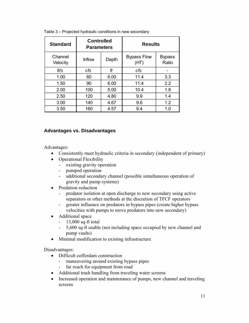
Table 3 – Projected hydraulic conditions in new secondary
Standard
Channel Velocity
Inflow Depth Bypass Flow (HT)
Bypass Ratio
ft/s cfs ft cfs -1.00 60 6.00 11.4 3.31.50 90 6.00 11.4 2.22.00 100 5.00 10.4 1.82.50 120 4.80 9.9 1.43.00 140 4.67 9.6 1.23.50 160 4.57 9.4 1.0
Controlled Parameters Results
Advantages vs. Disadvantages
Advantages: • Consistently meet hydraulic criteria in secondary (independent of primary) • Operational Flexibility
- existing gravity operation - pumped operation - additional secondary channel (possible simultaneous operation of
gravity and pump systems) • Predation reduction
- predator isolation at open discharge to new secondary using active separators or other methods at the discretion of TFCF operators
- greater influence on predators in bypass pipes (create higher bypass velocities with pumps to move predators into new secondary)
• Additional space - 13,000 sq-ft total - 5,600 sq-ft usable (not including space occupied by new channel and
pump vaults) • Minimal modification to existing infrastructure
Disadvantages: • Difficult cofferdam construction
- maneuvering around existing bypass pipes - far reach for equipment from road
• Additional trash handling from traveling water screens • Increased operation and maintenance of pumps, new channel and traveling
screens
11

12
The significant advantages of this design in conjunction with the hydraulic calculations summarized in Table 3 indicate that Alternative 2 is a feasible concept level design. The disadvantages that exist can be addressed by specialized construction techniques and additional planning and are not likely to become significant impediments to this design.
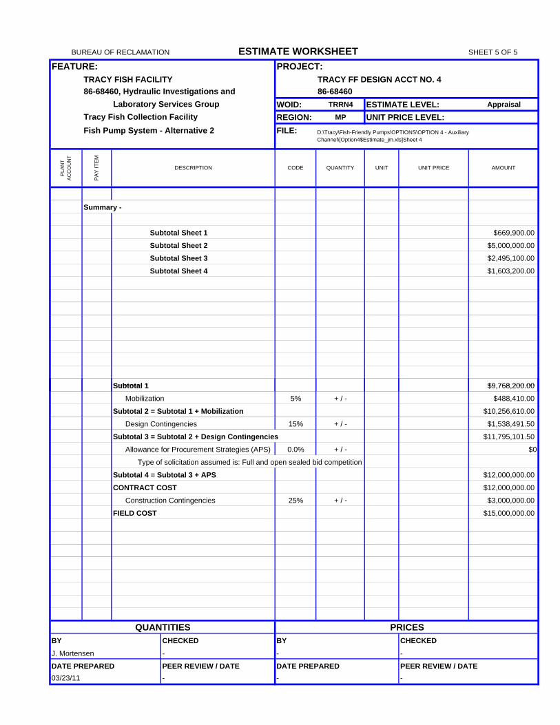
Costs • Total Construction Costs ≈ $15 million
- Hidrostal Pumps $5,000,000 - New Secondary $1,700,000 - Cofferdam and fill $1,600,000 - Piping, valves, electrical $930,000 - Pump vaults $550,000
• Moblization 5% • Design Contingencies 15% • Construction Contingencies 25%

13
Conclusions and Recommendations Two concept level design alternatives of a fish pump system were presented as a retrofit to improve hydraulic operation of the TFCF. Alternative 1 was determined to be non-feasible primarily due to space limitations at the facility. Although hydraulics in the secondary would be greatly improved, haul truck traffic would be permanently interrupted, utilities would be relocated, and a significant portion of the facility would be modified.
Alternative 2 was determined to be feasible and is recommended for further investigation and design. This design features four 28 inch diameter Wemco-Hidrostal pumps, one on each existing bypass pipe that diverts the flow to a new secondary channel. In the newly proposed secondary channel the fish are screened into a single bypass pipe that transports them to the existing holding tanks. This pump system will allow the facility to consistently meet hydraulic criteria independent of fluctuating water levels in the primary channel.
Alternative 2 is capable of enhancing overall TFCF performance by offering more options and operational flexibility. This pump system will be a retrofit to the existing facility without disrupting operation of the existing gravity system. With both pump and gravity options available, facility operation can be optimized and hydraulic criteria can be met consistently. Flow rates, velocities, and depths can be adjusted for target fish species or other events at the discretion of TFCF operators. Predation can be addressed by increasing bypass pipe velocities with the pumps and using the open discharge to separate large predators from other fish species using active separators or other methods. Also, having both gravity and pump options will allow the facility to continually operate during maintenance and/or repair to any part of the system.

14
References Borthwick, S.M., R.R. Corwin, and C.R. Liston, 1999. Investigations of Fish Entrainment by Archimedes and Internal Helical Pumps at the Red Bluff Research Pumping Plant, Sacramento River, California: February 1997 - June 1998. Red Bluff Research Pumping Plant Report Series, Volume 7, United States Department of the Interior, Bureau of Reclamation, Red Bluff, California and Denver. Colorado. 61 pp.
Borthwick, S.M., Weber, E.D., and R.R. Corwin, 2000. Travel Time and Condition of Juvenile Chinook Salmon Passed Through Archimedes Lifts, an Internal Helical Pump, and Bypasses at Red Bluff Research Pumping Plant, Sacramento River, California. Red Bluff Research Pumping Plant Report Series, Volume 11, United States Department of the Interior, Bureau of Reclamation, Red Bluff, California. 51 pp.
Borthwick, S.M., and C.R. Liston. 2003. Survival and External Condition of 200 - 300 mm Rainbow Trout Passed through an Archimedes Lift and a Hidrostal Pump at Red Bluff Research Pumping Plant. Tracy Fish Collection Facility Studies. Volume 25. U. S. Bureau of Reclamation, Mid-Pacific Region and Denver Technical Service Center. 33 pp.
Bureau of Reclamation. 2006. Fish Protection at Water Diversions. Water Resources Technical Publication. Bureau of Reclamation, Denver, CO.
California State Water Resources Control Board. 1978. Water Right Decision 1485 – Sacramento-San Joaquin Delta and Suisun Marsh. pg 40.
Helfrich, L., C. Liston, B. Mefford, and R. Bark. 2000. Assessment of Survival and Condition of Fish passed through a Hidrostal Pump at the Tracy Fish Collection Facility, California. Tracy Fish Collection Facility Studies. Volume 16. U. S. Bureau of Reclamation, Mid-Pacific Region and Denver Technical Service Center, and Virginia Polytechnic Institute and State University. 18 pp.
Helfrich, L.A., Bark, R., Liston, C.R., and B. Mefford. 2003. Survival and Condition of Striped Bass, Steelhead, Delta Smelt, and Wakasagi Passed through a Hidrostal Pump at the Tracy Fish Collection Facility, Tracy, California. Tracy Fish Collection Facility Studies. Volume 24. U. S. Bureau of Reclamation, Mid-Pacific Region and Denver Technical Service Center. 33 pp.
National Marine Fisheries Service. 2009. Biological opinion on the long-term operations of the Central Valley Project and State Water Project. National Marine Fisheries Service. Southwest Region, Long Beach, California.

APPENDIX A
ALTERNATIVE 1


APPENDIX B
ALTERNATIVE 2


2d Diameter: Wt per elbow = 3 elbow $405 00 $1 215 00
BUREAU OF RECLAMATION ESTIMATE WORKSHEET SHEET 1 OF 5
FEATURE: PROJECT:TRACY FISH FACILITY Central Valley Project - California86-68460, Hydraulic Investigations and
Laboratory Services Group WOID: AF555 ESTIMATE LEVEL: AppraisalTracy Fish Collection Facility REGION: MP UNIT PRICE LEVEL: Mar-11
Fish Pump System - Alternative 2 FILE: D:\Tracy\Fish-Friendly Pumps\OPTIONS\OPTION 4 - Auxiliary Channel\[Option4$Estimate_jm.xls]Sheet 4
PLA
NT
AC
CO
UN
T
PAY
ITEM
DESCRIPTION CODE QUANTITY UNIT UNIT PRICE AMOUNT
1 Furnish and install steel manifold 86-68460
Steel piping
1a 20" Sch. 10 Wt. = 53 lb/ft 100 lin ft. $180.00 $18,000.00
1b 24" Sch. 10 Wt. = 63.5 lb/ft 210 lin ft. $215.00 $45,150.00
1c 36" Sch. 5 Wt. = 95.5 lb/ft 60 lin ft. $300.00 $18,000.00
1d 60" PCCP 45 lin ft. $465.00 $20,925.00
2 Furnish and install steel pipe fittings 86-68460
Welded Lateral (Y)
2a 36" Diameter: Wt per lateral = 1000 lb 4 lateral $6,000.00 $24,000.00
22.5º Welded Elbow
2b 24" Diameter: Wt per elbow = 78 lb 4 elbow $375.00 $1,500.00
30º Welded Elbow
2c 24" Diameter: Wt per elbow = 105 lb 9 elbow $500.00 $4,500.00
45º Welded Elbow
2d 20" Diameter: Wt per elbow = 85 lb20" 85 lb 3 elbow $405 00. $1 215 00, .
2e 36" Diameter: Wt per elbow = 345 lb 4 elbow $1,500.00 $6,000.00
90º Welded Elbow
2f 20" Diameter: Wt per elbow = 170 lb 1 elbow $810.00 $810.00
2g 24" Diameter: Wt per elbow = 310 lb 4 elbow $1,500.00 $6,000.00
Welded 45º bend flares
2h 24" Diameter to 36"x54" rectangular flare 4 flare $9,000.00 $36,000.00
Welded Reducer 86-68460
2i 36" x 28" Wt. per reducer = 340 lb 4 reducer $2,500.00 $10,000.00
2j 28" x 24" Wt. per reducer = 265 lb 4 reducer $1,950.00 $7,800.00
3 Furnish and Install Valves 86-68460
3 20" Diameter Motorized Knife Gate Valve 2 valve $10,000.00 $20,000.00
3b 36" Diameter Motorized Knife Gate Valve 8 valve $50,000.00 $400,000.00
3c 60" Diameter Motorized Butterfly Valve 1 valve $50,000.00 $50,000.00
SUBTOTAL THIS SHEET $669,900.00
QUANTITIES PRICESBY CHECKED BY CHECKEDJ. Mortensen - - -
DATE PREPARED PEER REVIEW / DATE DATE PREPARED PEER REVIEW / DATE03/22/11 - - -

BUREAU OF RECLAMATION ESTIMATE WORKSHEET SHEET 2 OF 5
FEATURE: PROJECT:TRACY FISH FACILITY Central Valley Project - California86-68460, Hydraulic Investigations and
Laboratory Services Group WOID: AF555 ESTIMATE LEVEL: Appraisal
Tracy Fish Collection Facility REGION: MP UNIT PRICE LEVEL: Mar-11
Fish Pump System - Alternative 2 FILE: D:\Tracy\Fish-Friendly Pumps\OPTIONS\OPTION 4 - Auxiliary Channel\[Option4$Estimate_jm.xls]Sheet 4
PLAN
T AC
CO
UN
T
PA
Y IT
EM
DESCRIPTION CODE QUANTITY UNIT UNIT PRICE AMOUNT
FURNISH AND INSTALL THE FOLLOWING:Pump Items 5 Thru 9 - Complete 4 Ea $1,250,000.00 $5,000,000.00
PUMP w/ Falk Spacer Coupling to Gear Reducer
4 4 - Wemco Hidrostal Screw Centrifugal Fish Pump, 86-68420 44,000 lbs
Model M28DA/M700, single stage, 555 rpm,
Rated 18,000 gpm (40 cfs) pump @ 13' TDH,
28" diam. suction/discharge, water lube packing
(11,000 lbs each)
- stainless steel casing w/ stainless steel impeller
- stainless steel pump shaft
- pump vibration limits at Hydraulic Institute Stds
- Gov't-witnessed pump shop test
- pump shop testing with job motor & gear drive
RIGHT-ANGLE GEAR DRIVE SPEED REDUCER
5 4 - LFW right-angle gear reducer, 3.20:1 gear ratio, 86-68420 4,000 lbs
125 hp @ 1775 rpm,
(1,000 lbs each)
VERTICAL SHAFTING (motor to gear drive)
6 4 - Johnson Power vertical shafting, 14 feet total 86-68420 1,200 lbs
length (2 - 7' sections w/ end couplings &
1 steady bearing between sections)
(300 lbs each)
MOTOR
7 4 - Vertical, 50-degree C, inverter-rated motor,
WPI encl, 125 hp, 1800 rpm, solid shaft, Premium 86-68420 10,000 lbs
Efficiency, 460V/3Ph/60Hz
(2,500 lbs each)
VARIABLE-FREQUENCY DRIVE (VFD) & Enclosure
8 4 - Adjustable-speed drive unit for the pump motor, 86-68420 4 Ea
capable of operating down to 55% of full speed,
125 hp, NEMA 4 walk-in encl w/ air conditioner,
460V/3Ph/60HzSUBTOTAL THIS SHEET $5,000,000.00
QUANTITIES PRICESBY CHECKED BY CHECKED
R. Zelenka -- T. Hanke
DATE PREPARED PEER REVIEW / DATE DATE PREPARED PEER REVIEW / DATE08/31/10 -- 09/15/10

11b Channel Excavation 535 yd3 $30 00 $16 050 00
BUREAU OF RECLAMATION ESTIMATE WORKSHEET SHEET 3 OF 5
FEATURE: PROJECT:TRACY FISH FACILITY TRACY FF DESIGN ACCT NO. 486-68460, Hydraulic Investigations and 86-68460
Laboratory Services Group WOID: TRRN4 ESTIMATE LEVEL: AppraisalTracy Fish Collection Facility REGION: MP UNIT PRICE LEVEL:Fish Pump System - Alternative 2 FILE: D:\Tracy\Fish-Friendly Pumps\OPTIONS\OPTION 4 - Auxiliary
Channel\[Option4$Estimate_jm.xls]Sheet 4
PLA
NT
AC
CO
UN
T
PAY
ITEM
DESCRIPTION CODE QUANTITY UNIT UNIT PRICE AMOUNT
9 Electrical Work 86-68460
Assume necessary electric access already on site
Allocation for electrical work 1 LS $335,000.00 $335,000.00
10 Furnish and Install Traveling Fish Screen
Assume motors, sprayers, and conveyors included
10a Hydrolox traveling fish screen 86-68460 820 SF $1,320.00 $1,082,400.00
11 Excavation 86-68460
Assume common material stockpiled for reuse and backfill
Assume material stockpiled for reuse and backfill
Stockpiles will be located within 1/2 mile of site
11a Pump Vault Excavation 1,300 yd3 $30.00 $39,000.00
11b Channel Excavation 535 yd3 $30 00. $16 050 00, .
11c Bypass Pipe Excavation 120 yd3 $30.00 $3,600.00
Note: Item Unit Price includes placing and compacting backfill for structures
(approximately 33% of excavated quantity assumed)
12 Furnish, form and place reinforced conrete 86-68460
12a Vault Concrete 400 yd3 $1,250.00 $500,000.00
12b Channel Concrete 240 yd3 $1,250.00 $300,000.00
12c Bypass Concrete 165 yd3 $1,250.00 $206,250.00
13 Furnish and install sump pump for vault 86-68460
Allocation for sump pumps 1 LS $8,000.00 $8,000.00
14 Furnish and install grating 86-68460
48" x 48" grating around piping protruding 4 grate $1,200.00 $4,800.00
SUBTOTAL THIS SHEET $2,495,100.00
QUANTITIES PRICESBY CHECKED BY CHECKEDJ. Mortensen - - -
DATE PREPARED PEER REVIEW / DATE DATE PREPARED PEER REVIEW / DATE03/23/11 - - -

BUREAU OF RECLAMATION ESTIMATE WORKSHEET SHEET 4 OF 5
FEATURE: PROJECT:TRACY FISH FACILITY TRACY FF DESIGN ACCT NO. 486-68460, Hydraulic Investigations and 86-68460
Laboratory Services Group WOID: TRRN4 ESTIMATE LEVEL: AppraisalTracy Fish Collection Facility REGION: MP UNIT PRICE LEVEL:Fish Pump System - Alternative 2 FILE: D:\Tracy\Fish-Friendly Pumps\OPTIONS\OPTION 4 - Auxiliary
Channel\[Option4$Estimate_jm.xls]Sheet 4
PLA
NT
AC
CO
UN
T
PAY
ITEM
DESCRIPTION CODE QUANTITY UNIT UNIT PRICE AMOUNT
16 Furnish and place back fill material 86-68460
Assume compaction and hauling included
Assume fill is available within 25 miles from site
Backfill Material 3,200 yd3 $30.25 $96,800.00
17 Furnish and install sheet pile cofferdam 86-68460
Assume sheet piles will remain permanent
17a Steel sheet pile cofferdam 130 Ton $4,600.00 $598,000.00
17b Steel for permanent walers, bracing, etc. 6 Ton $1,400.00 $8,400.00
17c Specialized equipment, procedures, grouting, etc. for 3 Ea $200,000.00 $600,000.00
sheet piling around existing bypass pipes
18 Dewatering 86-68460
18a Allocation for dewatering 1 LS $300,000.00 $300,000.00
SUBTOTAL THIS SHEET $1,603,200.00
QUANTITIES PRICESBY CHECKED BY CHECKEDJ. Mortensen - - -
DATE PREPARED PEER REVIEW / DATE DATE PREPARED PEER REVIEW / DATE03/23/11 - - -
Subtotal 1 $9 768 200 00
BUREAU OF RECLAMATION ESTIMATE WORKSHEET SHEET 5 OF 5
FEATURE: PROJECT:TRACY FISH FACILITY TRACY FF DESIGN ACCT NO. 486-68460, Hydraulic Investigations and 86-68460
Laboratory Services Group WOID: TRRN4 ESTIMATE LEVEL: AppraisalTracy Fish Collection Facility REGION: MP UNIT PRICE LEVEL:Fish Pump System - Alternative 2 FILE: D:\Tracy\Fish-Friendly Pumps\OPTIONS\OPTION 4 - Auxiliary
Channel\[Option4$Estimate_jm.xls]Sheet 4
PLA
NT
AC
CO
UN
T
PAY
ITEM
DESCRIPTION CODE QUANTITY UNIT UNIT PRICE AMOUNT
Summary -
Subtotal Sheet 1 $669,900.00
Subtotal Sheet 2 $5,000,000.00
Subtotal Sheet 3 $2,495,100.00
Subtotal Sheet 4 $1,603,200.00
Subtotal 1 $9 768 200 00, , .
Mobilization 5% + / - $488,410.00
Subtotal 2 = Subtotal 1 + Mobilization $10,256,610.00
Design Contingencies 15% + / - $1,538,491.50
Subtotal 3 = Subtotal 2 + Design Contingencies $11,795,101.50
Allowance for Procurement Strategies (APS) 0.0% + / - $0
Type of solicitation assumed is: Full and open sealed bid competition
Subtotal 4 = Subtotal 3 + APS $12,000,000.00
CONTRACT COST $12,000,000.00
Construction Contingencies 25% + / - $3,000,000.00
FIELD COST $15,000,000.00
QUANTITIES PRICESBY CHECKED BY CHECKEDJ. Mortensen - - -
DATE PREPARED PEER REVIEW / DATE DATE PREPARED PEER REVIEW / DATE03/23/11 - - -

ALTERNATIVE 2 - PROJECTED HYDRAULIC CONDITIONSStandard
Channel Velocity
Single Pump Flow Inflow
36" Suction Pipe
Velocity
24" Discharge Pipe Velocity
Flare Discharge Velocity
Depth Vertical Fish Drop
Fish Impact
Velocity
Energy Dissipation
Factor
Screen Approach Velocity
Bypass Ratio
ft/s cfs cfs ft/s ft/s ft/s ft ft ft/s ft lb/s/ft^3 ft/s -1.00 30.00 60 4.24 9.55 1.11 6.00 4.50 17.06 10.14 0.10 3.31.50 22.50 90 3.18 7.16 1.67 6.00 4.50 17.10 15.30 0.16 2.22.00 25.00 100 3.54 7.96 1.85 5.00 5.50 18.91 24.93 0.22 1.82.50 30.00 120 4.24 9.55 2.22 4.80 5.70 19.29 32.42 0.28 1.43.00 35.00 140 4.95 11.14 2.59 4.67 5.83 19.55 39.98 0.34 1.23.50 40.00 160 5.66 12.73 2.96 4.57 5.93 19.76 47.65 0.40 1.0
Fish Pumps New Secondary Channel

APPENDIX C
DRAWINGS OF OTHER CONCEPT DESIGNS CONSIDERED
Both concepts shown in Appendix C were not considered feasible because the system did not match the required pump curve of the pump size required to meet secondary flow requirements. They also presented issues for space limitations.