Embed Size (px)
Citation preview
GLOBAL STANDARD Page 1 of 16
CONCENTRIC-LAY-STRANDED BARE CONDUCTORS GSC003
Rev. 2 29/04/2016
CONCENTRIC-LAY-STRANDED BARE CONDUCTORS
This document is intellectual property of Enel Spa; reproduction or distribution of its contents in any way or by any means whatsoever is subject to the prior approval of the above mentioned company which will safeguard its rights under the civil and penal codes. This document is for Internal Use.
Elaborated by Verified by Approved by
Solution Development Center L. Foddai R. Emma I. Gentilini
Global I&N – NT/NCS N. Cammalleri N. Cammalleri G. Egea Brufau F. Giammanco
Revision Data List of modifications
0 16/05/2014 First emission
01 15/09/2014 Second emission
02 29/04/2016 Updated common list
GLOBAL STANDARD Page 2 of 16
CONCENTRIC-LAY-STRANDED BARE CONDUCTORS GSC003
Rev. 2 29/04/2016
CONTENTS
1 SCOPE ........................................................................................................................................................... 3 2 LIST OF CONDUCTORS ............................................................................................................................... 3 3 REFERENCE LAWS AND STANDARDS ...................................................................................................... 4 4 See local section. TERMINOLOGY ................................................................................................................ 5 5 DESIGN AND MANUFACTURE ..................................................................................................................... 5 6 TESTS ............................................................................................................................................................ 8 7 CONDITIONS OF SUPPLY ............................................................................................................................ 9 8 PACKING AND MARKING ............................................................................................................................. 9 9 LENGTH TOLERANCE .................................................................................................................................. 9 10 Warranty ....................................................................................................................................................... 9
LOCAL SECTION
A LATAM: Ampla (Brazil), Chilectra (Chile), Codensa (Colombia), Coelce (Brazil), Edelnor
(Perù), Edesur (Argentine) B ENDESA DISTRIBUCIÓN ELÉCTRICA (Spain) C ENEL DISTRIBUZIONE (Italy), ENEL DISTRIBUTIE: Banat, Dobrogea, Muntenia,
(Romania)
GLOBAL STANDARD Page 3 of 16
CONCENTRIC-LAY-STRANDED BARE CONDUCTORS GSC003
Rev. 2 29/04/2016
1 SCOPE
The aim of this document is to provide technical requirements for the supply of concentric –lay-stranded bare conductors to be used in the overhead electrical distribution lines of the Enel Group Distribution Companies, listed below:
• Ampla (AM) Brasil • Chilectra (CH) Chile • Codensa (CD) Colombia • Coelce (CE) Brasil • Edelnor (EN) Perú • Edesur (ES) Argentina
• Endesa Distribución Eléctrica (EE) España • Enel Distributie Banat (ER) Romania • Enel Distributie Dobrogea (ER) Romania • Enel Distributie Muntenia (ER) Romania • ENEL Distribuzione (ED) Italy
2 LIST OF CONDUCTORS
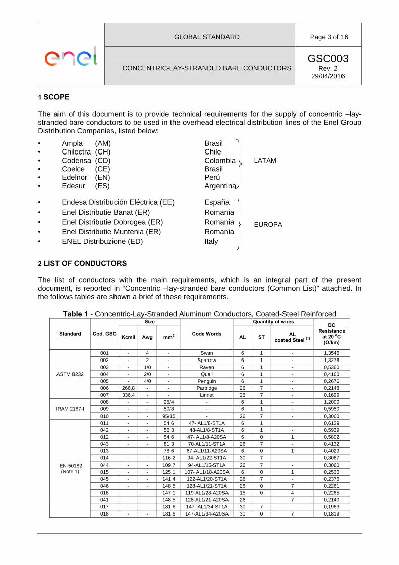
The list of conductors with the main requirements, which is an integral part of the present document, is reported in “Concentric –lay-stranded bare conductors (Common List)” attached. In the follows tables are shown a brief of these requirements.
Table 1 - Concentric-Lay-Stranded Aluminum Conductors, Coated-Steel Reinforced
Standard Cod. GSC
Size
Code Words
Quantity of wires DC
Resistance at 20 oC (Ω/km)
Kcmil Awg mm2 AL ST AL coated Steel (1)
ASTM B232
001 - 4 - Swan 6 1 - 1,3545 002 - 2 - Sparrow 6 1 - 1,3278 003 - 1/0 - Raven 6 1 - 0,5360 004 - 2/0 - Quail 6 1 - 0,4160 005 - 4/0 - Penguin 6 1 - 0,2676 006 266,8 - - Partridge 26 7 - 0,2148 007 336.4 - - Linnet 26 7 - 0,1699
IRAM 2187-I 008 - - 25/4 - 6 1 - 1,2000 009 - - 50/8 - 6 1 - 0,5950 010 - - 95/15 - 26 7 - 0,3060
EN-50182 (Note 1)
011 - - 54,6 47- AL1/8-ST1A 6 1 0,6129 042 - - 56.3 48-AL1/8-ST1A 6 1 - 0.5939 012 - - 54,6 47- AL1/8-A20SA 6 0 1 0,5802 043 - - 81.3 70-AL1/11-ST1A 26 7 - 0.4132 013 78,6 67-AL1/11-A20SA 6 0 1 0,4029 014 - - 116,2 94- AL1/22-ST1A 30 7 0,3067 044 - - 109.7 94-AL1/15-ST1A 26 7 - 0.3060 015 - - 125,1 107- AL1/18-A20SA 6 0 1 0,2530 045 - - 141.4 122-AL1/20-ST1A 26 7 - 0.2376 046 - - 148.5 128-AL1/21-ST1A 26 0 7 0.2261 016 147,1 119-AL1/28-A20SA 15 0 4 0,2265 041 148,5 128-AL1/21-A20SA 26 7 0,2140 017 - - 181,6 147- AL1/34-ST1A 30 7 0,1963 018 - - 181,6 147-AL1/34-A20SA 30 0 7 0,1819
LATAM
EUROPA
GLOBAL STANDARD Page 4 of 16
CONCENTRIC-LAY-STRANDED BARE CONDUCTORS GSC003
Rev. 2 29/04/2016
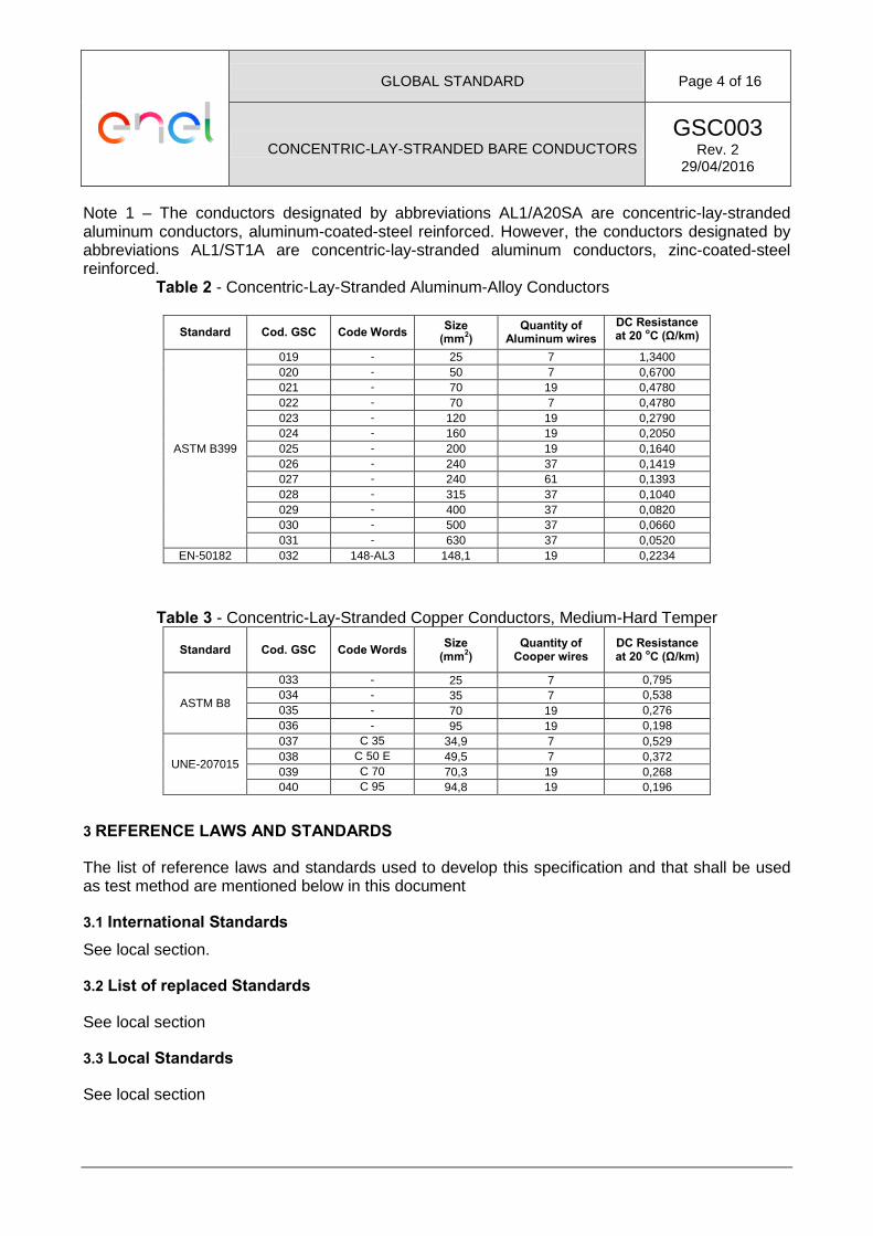
Note 1 – The conductors designated by abbreviations AL1/A20SA are concentric-lay-stranded aluminum conductors, aluminum-coated-steel reinforced. However, the conductors designated by abbreviations AL1/ST1A are concentric-lay-stranded aluminum conductors, zinc-coated-steel reinforced.
Table 2 - Concentric-Lay-Stranded Aluminum-Alloy Conductors
Standard Cod. GSC Code Words Size (mm2)
Quantity of Aluminum wires
DC Resistance at 20 oC (Ω/km)
ASTM B399
019 - 25 7 1,3400 020 - 50 7 0,6700 021 - 70 19 0,4780 022 - 70 7 0,4780 023 - 120 19 0,2790 024 - 160 19 0,2050 025 - 200 19 0,1640 026 - 240 37 0,1419 027 - 240 61 0,1393 028 - 315 37 0,1040 029 - 400 37 0,0820 030 - 500 37 0,0660 031 - 630 37 0,0520
EN-50182 032 148-AL3 148,1 19 0,2234
Table 3 - Concentric-Lay-Stranded Copper Conductors, Medium-Hard Temper
Standard Cod. GSC Code Words Size (mm2)
Quantity of Cooper wires
DC Resistance at 20 oC (Ω/km)
ASTM B8
033 - 25 7 0,795 034 - 35 7 0,538 035 - 70 19 0,276 036 - 95 19 0,198
UNE-207015
037 C 35 34,9 7 0,529 038 C 50 E 49,5 7 0,372 039 C 70 70,3 19 0,268 040 C 95 94,8 19 0,196
3 REFERENCE LAWS AND STANDARDS
The list of reference laws and standards used to develop this specification and that shall be used as test method are mentioned below in this document
3.1 International Standards See local section.
3.2 List of replaced Standards
See local section
3.3 Local Standards
See local section
GLOBAL STANDARD Page 5 of 16
CONCENTRIC-LAY-STRANDED BARE CONDUCTORS GSC003
Rev. 2 29/04/2016
4 See local section. TERMINOLOGY
In addition to IEC 60050-466 terminology, the following ones shall be noted:
• Direction of lay: The direction of lay is defined as right-hand or left-hand. With right-hand lay, the wires conform to the direction of the central part of the letter Z when the conductor is held vertically. With left-hand lay, the wires conform to the direction of the central part of letter S when the conductor is held vertically;
• Lay ratio: means the ratio of the axial length of one complete turn of the helix formed by the the wire of a stranded conductor to the external diameter of the corresponding layer of wires;
• Nominal: the name or identifying value of a measurable property by which a conductor or component of a conductor is identified ant to which tolerance are applied. Nominal values should be target values;
• Wire: a filament of draw metal having a constant circular cross-section;
• Rated Tensile Strength: sum of the tensile strength of all wires considering the rupture load of the weakest wire.
5 DESIGN AND MANUFACTURE
5.1 RAW MATERIALS OF WIRES The following sections provides general information about the raw material of wires considered in this Global Standard. Specific characteristics are detailed in Common List.
5.1.1 Zinc-Coated (Galvanized) Steel Core Wires Zinc-Coated (Galvanized) Steel Core Wires used for mechanical reinforcement in the manufacture of aluminum conductors, must be manufactured with the requirements of the standards shown in the section 3.1 of the Local Section.
5.1.2 Aluminum-Coated (Aluminized) Steel Core Wires Aluminum-Coated (Aluminized) Steel Core Wires used for mechanical reinforcement in the manufacture of aluminum conductors, must be manufactured with the requirements of the EN 61232. The wires shall be “20SA” class and “A” type.
5.1.3 Aluminum Wires Aluminum wires used to assemble the bare conductors considered in this Global Standard shall be made of pure aluminum, manufacture under the standards EN 60889 or IEC 60889, or aluminum 1350-H19, manufacture under the standard ASTM B230 y ASTM B231, as indicated in the section 3.1 of the Local Section.
5.1.4 Aluminum-Alloy Wires Aluminum-alloy wires used to assemble the bare conductors considered in this Global Standard shall be made of 6201-T81 aluminum-alloy under the standard ASTM B398 or identified as AL3 under the standard Norma EN 50183, as indicated in the section 3.1 of the Local Section.
GLOBAL STANDARD Page 6 of 16
CONCENTRIC-LAY-STRANDED BARE CONDUCTORS GSC003
Rev. 2 29/04/2016
5.1.5 Copper wires Copper wires shall be uncoated, under the standards ASTM B2 or UNE 207015, as indicated in the section 3.1 and 3.3 of the Local Section.
5.2 CONSTRUCCIÓN The following sections provides the description of the conductors in function of the wires use to assemble them. The Standards use to manufacture the conductors are indicated in the Common List and in the section 2.
5.2.1 Aluminum Conductors Aluminum conductors shall be assembled with aluminum wires, as indicated in the section 5.1.3.
5.2.2 Aluminum Conductors, Zinc-Coated-Steel Reinforced Aluminum conductors, coated-steel reinforced are assembled with aluminum wires (see 5.1.3) in the external layers and zinc-coated (galvanized) steel core wires in the internal layers ( see 5.1.1).
5.2.3 Aluminum Conductors, Aluminum-Coated-Steel Reinforced Aluminum conductors, aluminum-coated-steel reinforced are assembled with aluminum wires (see 5.1.3) in the external layers and aluminum-coated (Aluminized) steel core wires in the internal layers (see 5.1.2).
5.2.4 Alloy-aluminum conductors The alloy-aluminum conductors shall be assembled with alloy-aluminum wires, as indicated in the section 5.1.4.
5.2.5 Copper conductors The uncompressed copper conductors shall be assembled with copper wire, as indicated in the section 5.1.5.
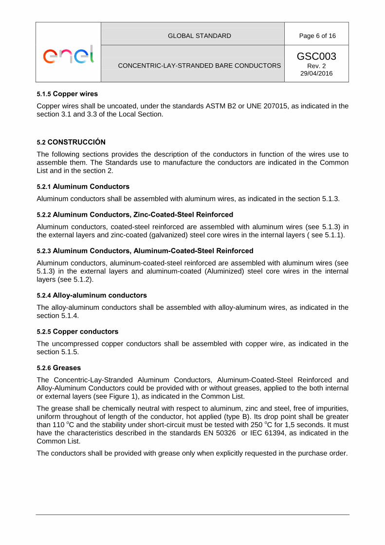
5.2.6 Greases The Concentric-Lay-Stranded Aluminum Conductors, Aluminum-Coated-Steel Reinforced and Alloy-Aluminum Conductors could be provided with or without greases, applied to the both internal or external layers (see Figure 1), as indicated in the Common List.
The grease shall be chemically neutral with respect to aluminum, zinc and steel, free of impurities, uniform throughout of length of the conductor, hot applied (type B). Its drop point shall be greater than 110 oC and the stability under short-circuit must be tested with 250 oC for 1,5 seconds. It must have the characteristics described in the standards EN 50326 or IEC 61394, as indicated in the Common List.
The conductors shall be provided with grease only when explicitly requested in the purchase order.
GLOBAL STANDARD Page 7 of 16
CONCENTRIC-LAY-STRANDED BARE CONDUCTORS GSC003
Rev. 2 29/04/2016
Figure 1 – Greased Conductors.
The volume of the grease shall be calculated with the following equation:
Vg = 0,25 π (Do2 - na da
2 – ns ds2)
Where:
Vg = Volume of grease per length
Do = outer diameter for the conductor
da = diameter of the aluminum wire
ds = diameter of steel wire.
na = number of aluminum wires in the conductor
ns = number of steel wires in the conductor
Consequently, with the density of the grease of 0,87 g/cm3 and with fill factor of 0,8, the mass of the grease will be:
Mg = 0,8 Vg δ
Mg = mass of grease per length
δ = density of grease
5.3 SURFACE The surface of the conductor shall be free from all imperfections visible to the unaided eye (normal corrective lenses accepted), such as nicks, indentations, etc., not consistent with good commercial practice.
5.4 Conductor diameter The diameter of the conductor shall not vary from the nominal values more than the limits indicated in the standards shown in the Common List.
5.5 Stranding All wires of the conductor shall be concentrically stranded.
GLOBAL STANDARD Page 8 of 16
CONCENTRIC-LAY-STRANDED BARE CONDUCTORS GSC003
Rev. 2 29/04/2016
Adjacent wire layers shall be stranded with reverse lay directions. The directions of lay of the external layer shall be “right-hand” to aluminum conductors. The direction of lay of the extern layer to copper conductor shall be “right-hand” or “left-hand”, as indicated in the Local Section.
The wires in each layer shall be every and closely stranded around the underlying wire of wires.
5.6 Joints Conductors with only one steel wire, shall not be made any joints after heat treatment of wires or rods. There shall be no joints of any kind made in the zinc-coated or aluminum-coated steel core wire or wires during stranding.
Before stranding, no more than one joint shall be accepted in the aluminum wires per length of conductor. During stranding, no wire welds shall be made for the purpose of achieving the required conductor length.
Joints are permitted in aluminum or copper wires unavoidably broken during stranding, provided such breaks are not associated with either inherently defective wire or with the use of short lengths of wires. Joints shall conform to the geometry of original wire, i.e., joints shall be dressed smoothly with a diameter equal to that of the parent wires and shall not be kinked. Joints shall not be made in the finished copper wires composing conductors of seven wires or less.
Joints in wires shall not be closer than 15 m form a joint in the same wire or in any other wire of the completed conductor. The quantity of joints per length shall not greater than values indicated in the standards shown in the Common List.
Joints shall be made by electric butt welding, electric butt cold upset welding or cold pressure welding and other approved methods. These joints shall be made in accordance with good commercial practice. The first type of joints shall be electrically annealed for approximately 250 mm on both sides of the weld.
5.7 Mass per unit of length The mass per unit length of the conductor shall be calculated using densities, stranding increments and cross-sectional areas of all kind of wires. The mass per unit length of the conductor without grease shall not vary from its nominal value by more than ± 2 %.
5.8 Rated tensile strength Rated tensile strength are result of sum of the tensile strength of all wires that compose the conductor, as indicated in the standards shown in the Common List.
5.9 Electrical resistance The electrical DC resistance at 20 oC of a conductor, expressed in Ω / km and with three decimals, is calculated using the value of the resistivity of the wires used.
6 TESTS
6.1 Type Test Type test shall be carried out over conductors considered in this Global Standard in order to verify its main characteristics that depended mainly on its design
Each manufacture shall make these tests once for a new design or manufacturing process of conductor and the subsequently repeated only when the design or manufacturing process is
GLOBAL STANDARD Page 9 of 16
CONCENTRIC-LAY-STRANDED BARE CONDUCTORS GSC003
Rev. 2 29/04/2016
changed. The type test shall be analyzed by the purchaser using the requirements of this Global Standard and requirements of his homologation procedures.
The list of type tests of wires and conductors are shown in the Local Section and shall be carried out as the procedures of standards indicated in the Common List.
6.2 Sample test
Sample test shall be carried out to guarantee the quality of conductors and compliance with the requirements of this standard. Shall be informed in the purchase order about the presence of a inspector as representative of the purchaser during the sample tests
The list of sample tests of wires and conductors are shown in the Local Section and shall be carried out as the procedures of standards indicated in the Common List.
7 CONDITIONS OF SUPPLY
The conductor shall be suitably protected against damage which could in ordinary handling and shipping. The reel shall be protected with staves or similar protection
The reel shall be capable to supporting the weight of the conductor both during and after transport, by truck, crane movements or forklift truck, without cause damage to the conductor.
The drum bore shall be capable to supporting the weight of the conductor and respect the minimum bend radio.
The reel shall be loaded and unloaded by crane capable to support its weight.
These ends internally secured to the spools, must be mechanically protected against possible damages resulting from handling and transportation of each spool, leaving both ends accessible through the use of an internal helix or reel on each spool.
Specific characteristics are detailed in Local Section.
8 PACKING AND MARKING
Each reel shall be identified with a indelible and easily legible mark on the external faces, as indicated in the Local Section
9 LENGTH TOLERANCE
The admitted tolerance for a size is equal to ± 5% of the length indicated in the order. The equipment used to measure the length of the conductor shall be accurate to ± 1%.
10 Warranty
Requirement of warranty will be indicated the moment of request for bids it, indicating periods and standards.
GLOBAL STANDARD Page 10 of 16
CONCENTRIC-LAY-STRANDED BARE CONDUCTORS GSC003
Rev. 2 29/04/2016
LOCAL SECTION A – LATAM: Ampla (Brazil), Chilectra (Chile), Codensa (Colombia), Coelce (Brazil), Edelnor (Perù), Edesur (Argentina)
ITEM TITLE DESCRIPTION
3.1 International Standards Ampla(Brasil), Coelce(Brasil), Chilectra (Chile), Codensa(Colombia), Edelnor (Perú) • ASTM B398: Standard Specification for Aluminum-Alloy 6201-T81 Wire for Electrical
Purposes. • ASTM B399: Standard Specification for Concentric-Lay-Stranded Aluminum-Alloy
6201-T81 Conductors. • ASTM B230: Standard Specification for Aluminum 1350-H19 Wire for Electrical
Purposes. • ASTM B232: Standard Specification for Concentric-Lay-Stranded Aluminum
Conductors, Coated-Steel Reinforced (ACSR). • ASTM B498: Standard Specification for Zinc-Coated (Galvanized) Steel Core Wire for
Aluminum Conductors, Steel Reinforced (ACSR). • ASTM B500: Standard Specification for Metallic Coated Stranded Steel Core for
Aluminum Conductors, Steel Reinforced (ACSR). • ASTM B2: Standard specification for médium-hard-grawn copper wire. • ASTM B8: Standard specification for concentric-lay-stranded copper conductors,
hard médium-hard, or soft. .
3.2 List of replaced Standards
Ampla(Brasil), Coelce(Brasil), Chilectra (Chile), Codensa(Colombia), Edelnor (Perú), Edesur(Argentina)
• E-MT-003: Especificación Técnica de Conductores desnudos para líneas aéreas de tensión hasta 36 kV.
3.3 Local Standards Edesur(Argentina)
• IRAM 2187-I: Conductores de aluminio y de aleación de aluminio con alma de acero
de resistencia mecánica normal para líneas aéreas de energía.
Codensa (Colombia).
• RETIE: Reglamento Técnico de Instalaciones Eléctricas.
5.1.5 Copper wires Ampla (Brazil), Chilectra (Chile),Codensa (Colombia), Coelce (Brazil), Edelnor (Perú), Edesur (Argentina). Copper wires shall be medium-hard temper, uncoated, under the standards ASTM B2.
5.2.6 Greases Ampla (Brazil), Chilectra (ChileCoelce (Brazil), Edelnor (Perú), Edesur (Argentina).
Shall be applied the standard IEC- 61089.
Ampla (Brazil),
Conductors shall be provided with greases, applied to the internal layers as indicated in the Common List. Edelnor (Perú),
Conductors shall be provided with greases, applied to the both internal or external layers as indicated in the Common List.
Codensa (Colombia),
It is not required greases for conductors.
GLOBAL STANDARD Page 11 of 16
CONCENTRIC-LAY-STRANDED BARE CONDUCTORS GSC003
Rev. 2 29/04/2016
5.5 Stranding Ampla(Brasil), Coelce(Brasil), Chilectra (Chile), Codensa(Colombia), Edelnor (Perú), Edesur(Argentina)
The directions of lay of the external layer shall be “left-hand” to copper conductors.
6.1 Type Test Ampla(Brasil), Coelce(Brasil), Chilectra (Chile), Codensa(Colombia), Edelnor (Perú), Edesur(Argentina)
• Surface Condition • Overall Diameter • Number and type of wires • Cross section area • Mass per unit length • Rated tensile strength • Elongation • Joints • Electrical resistance • Lay ratio and direction of lay • Grease temperature characteristics For Edesur consider the standard IRAM-2187-I
6.2 Sample test Ampla(Brasil), Coelce(Brasil), Chilectra (Chile), Codensa(Colombia), Edelnor (Perú), Edesur(Argentina)
• Number and type of wires • Cross section area • Lay ratio and direction of lay • Mass per unit length • Rated tensile strength (wires) • Electrical resistance (wires) • Grease temperature characteristics
The acceptance level shall be determined according to the procedure described in standard IEC 60410 considering AQL 1,5%, level II, simple sampling.
For Edesur consider the standard IRAM-2187-I
7 CONDITIONS OF SUPPLY
Ampla (Brazil), Chilectra (Chile),Codensa (Colombia), Coelce (Brazil), Edelnor (Perú), Edesur (Argentina).
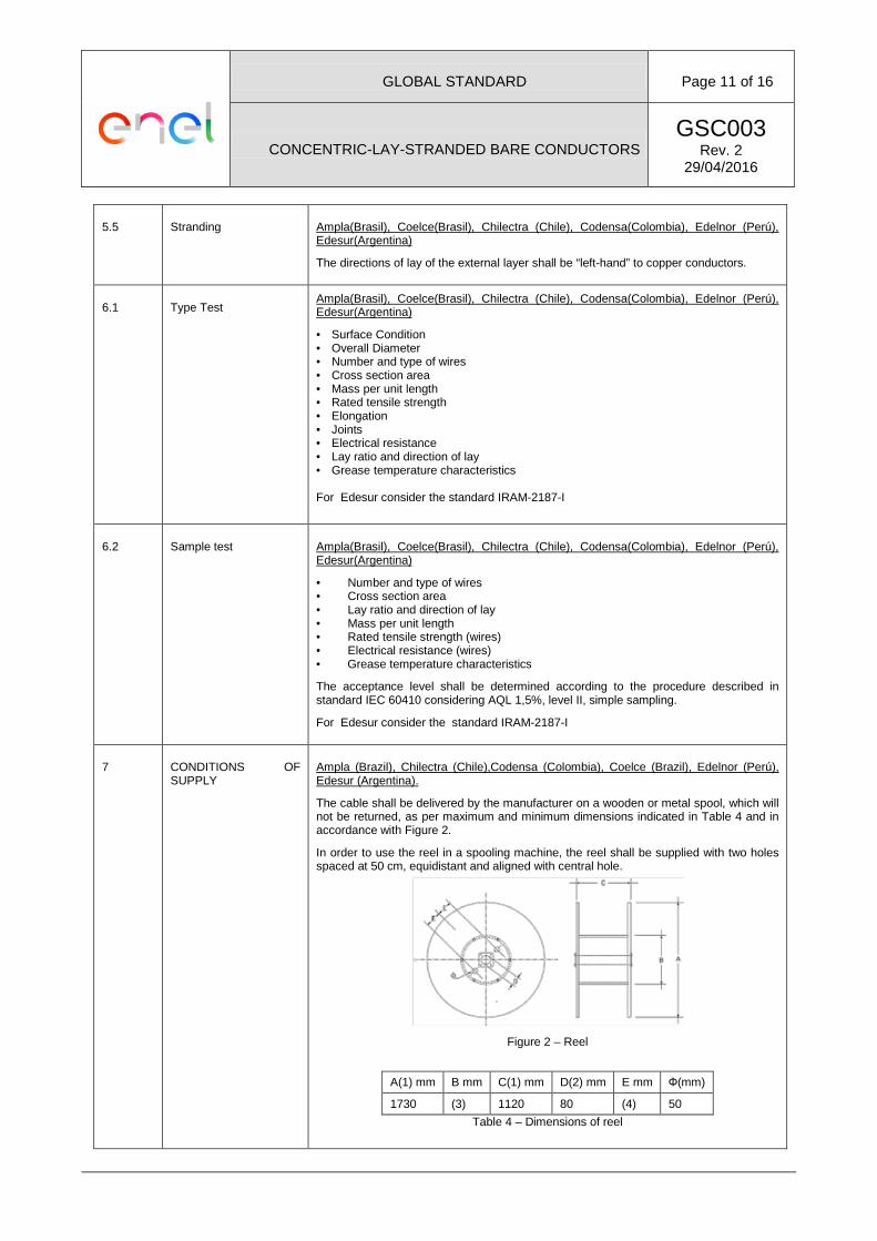
The cable shall be delivered by the manufacturer on a wooden or metal spool, which will not be returned, as per maximum and minimum dimensions indicated in Table 4 and in accordance with Figure 2.
In order to use the reel in a spooling machine, the reel shall be supplied with two holes spaced at 50 cm, equidistant and aligned with central hole.
Figure 2 – Reel
A(1) mm B mm C(1) mm D(2) mm E mm Ф(mm)
1730 (3) 1120 80 (4) 50 Table 4 – Dimensions of reel
GLOBAL STANDARD Page 12 of 16
CONCENTRIC-LAY-STRANDED BARE CONDUCTORS GSC003
Rev. 2 29/04/2016
Notes: (1) Maximum value (2) Minimum value (3) Twice of the minimum bend ratio of conductor used to transport , as indicated by
the manufacturer. (4) 300 ó 180 mm , according to the type of reel.
The wooden spools shall be treated according to the international requirements for the control of plant disease, avoiding the compounds “Pentachlorophenol” and “Creosote”. The treatment must include, at least: highly toxic to xylophagous organisms, high penetration and holding power, chemical stability, non-corrosive substances to metals nor should they affect the physical characteristics of wood.
Each reel shall be protected with a plastic coat than avoids the corrosion of the conductor.
The total length of the cable supplied may not be less than that requested in the purchase order and shall not be longer by any more than 1%.
The maximum gross weight of the packaged spool must not exceed 2500 kg.
Codensa (Colombia)
In additional to above specified, for Codensa the manufacturers shall to attach the RETIE certification in the first supply.
8 PACKING AND MARKING
Ampla (Brazil), Chilectra (Chile),Codensa (Colombia), Coelce (Brazil), Edelnor (Perú), Edesur (Argentina).
The spools must:
Indicate the correct rolling direction with an arrow on its side.
Have a stainless steel plate for its identification on each side, each one of which must include at least the following information, in the language of the country where it will be used (Spanish or Portuguese):
• Name of the manufacturer • Country of origin of the item • ENEL GROUP • Purchase Order N° • Conductor caliber (en mm²) • Number of the spool within the delivered batch. • Net weight and gross weight in kg. • Cable type • Cable length, in meters.
GLOBAL STANDARD Page 13 of 16
CONCENTRIC-LAY-STRANDED BARE CONDUCTORS GSC003
Rev. 2 29/04/2016
B SECCIÓN LOCAL – ENDESA DISTRIBUCIÓN ELÉCTRICA (España)
ITEM TITLE DESCRIPTION
3.1 International Standards
• IEC 60050-466: Vocabulario electrotécnico internacional. Líneas aéreas. • EN 50182: Conductores para líneas eléctricas aéreas. Conductores de
alambres redondos cableados en capas concéntricas. • EN 50183: Conductores para líneas eléctricas aéreas. Alambres en aleación
de aluminio-magnesio-silicio. • EN 50189: Conductores para líneas eléctricas aéreas. Alambres de acero
galvanizado. • EN 60889: Alambre de aluminio duro para Conductores de líneas aéreas de
transporte de energía eléctrica. • EN 61232: Alambres de acero recubiertos de aluminio para usos eléctricos. • EN 50326: Conductores para líneas eléctricas aéreas. Características de los
productos de protección (grasas).
3.2 List of replaced Standards
• Norma GE AND010: Conductores desnudos para líneas eléctricas aéreas de media tensión hasta 30kV.
3.3 Local Standards • UNE 20003: Cobre-tipo recocido e industrial, para aplicaciones eléctricas. • UNE 21045: Bobinas de madera destinadas a conductores desnudos para
conductores de líneas eléctricas aéreas. • UNE 207015: Conductores desnudos de cobre duro cableados para líneas
eléctricas aéreas. • UNE 21044: Planes de muestreo y criterios de aceptación y rechazo en la
recepción de cables desnudos para conductores de I íneas eléctricas aéreas
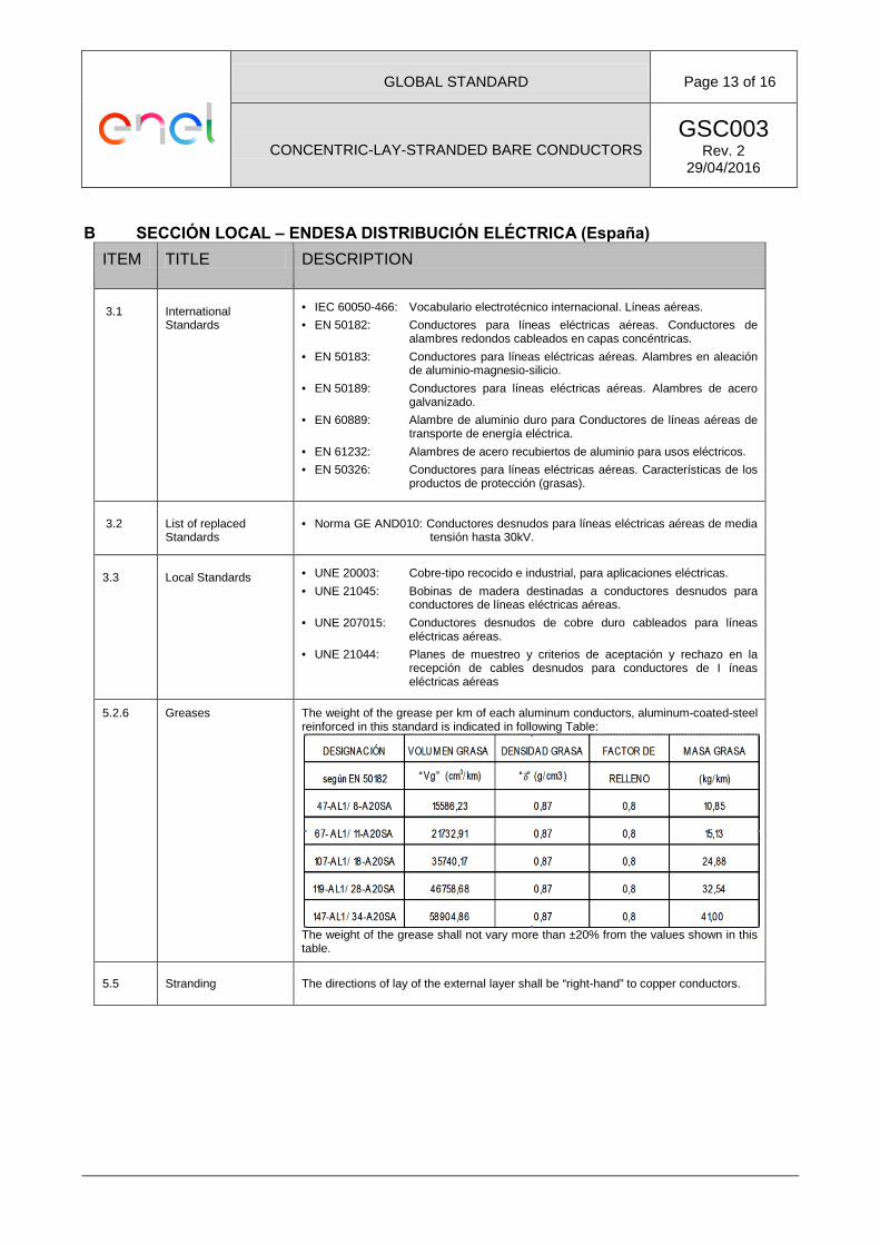
5.2.6 Greases The weight of the grease per km of each aluminum conductors, aluminum-coated-steel reinforced in this standard is indicated in following Table:
The weight of the grease shall not vary more than ±20% from the values shown in this table.
5.5 Stranding The directions of lay of the external layer shall be “right-hand” to copper conductors.
GLOBAL STANDARD Page 14 of 16
CONCENTRIC-LAY-STRANDED BARE CONDUCTORS GSC003
Rev. 2 29/04/2016
ITEM TITLE DESCRIPTION
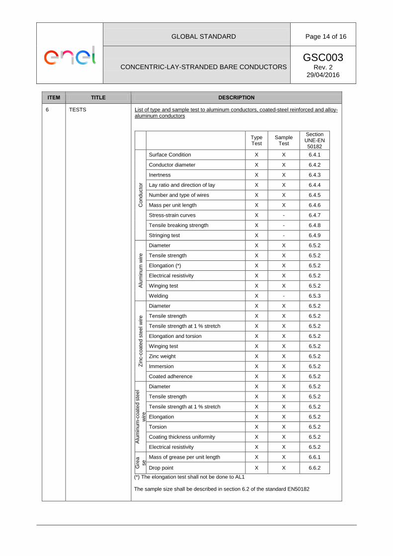
6 TESTS List of type and sample test to aluminum conductors, coated-steel reinforced and alloy-aluminum conductors
Type
Test Sample
Test
Section UNE-EN 50182
Con
duct
or
Surface Condition X X 6.4.1
Conductor diameter X X 6.4.2
Inertness X X 6.4.3
Lay ratio and direction of lay X X 6.4.4
Number and type of wires X X 6.4.5
Mass per unit length X X 6.4.6
Stress-strain curves X - 6.4.7
Tensile breaking strength X - 6.4.8
Stringing test X - 6.4.9
Alu
min
um w
ire
Diameter X X 6.5.2
Tensile strength X X 6.5.2
Elongation (*) X X 6.5.2
Electrical resistivity X X 6.5.2
Winging test X X 6.5.2
Welding X - 6.5.3
Zinc
-coa
ted
stee
l wire
Diameter X X 6.5.2
Tensile strength X X 6.5.2
Tensile strength at 1 % stretch X X 6.5.2
Elongation and torsion X X 6.5.2
Winging test X X 6.5.2
Zinc weight X X 6.5.2
Immersion X X 6.5.2
Coated adherence X X 6.5.2
Alu
min
um-c
oate
d st
eel
wire
Diameter X X 6.5.2
Tensile strength X X 6.5.2
Tensile strength at 1 % stretch X X 6.5.2
Elongation X X 6.5.2
Torsion X X 6.5.2
Coating thickness uniformity X X 6.5.2
Electrical resistivity X X 6.5.2
Gre
ase
Mass of grease per unit length X X 6.6.1
Drop point X X 6.6.2
(*) The elongation test shall not be done to AL1 The sample size shall be described in section 6.2 of the standard EN50182
GLOBAL STANDARD Page 15 of 16
CONCENTRIC-LAY-STRANDED BARE CONDUCTORS GSC003
Rev. 2 29/04/2016
ITEM TITLE DESCRIPTION
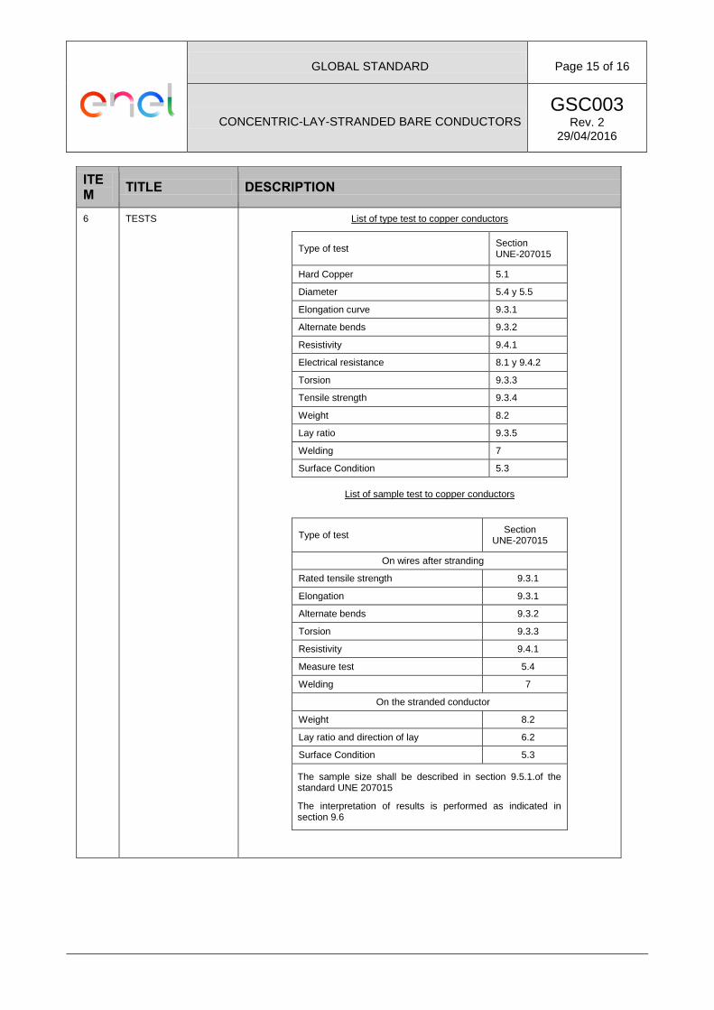
6 TESTS List of type test to copper conductors
Type of test Section UNE-207015
Hard Copper 5.1
Diameter 5.4 y 5.5
Elongation curve 9.3.1
Alternate bends 9.3.2
Resistivity 9.4.1
Electrical resistance 8.1 y 9.4.2
Torsion 9.3.3
Tensile strength 9.3.4
Weight 8.2
Lay ratio 9.3.5
Welding 7
Surface Condition 5.3
List of sample test to copper conductors
Type of test Section UNE-207015
On wires after stranding
Rated tensile strength 9.3.1
Elongation 9.3.1
Alternate bends 9.3.2
Torsion 9.3.3
Resistivity 9.4.1
Measure test 5.4
Welding 7
On the stranded conductor
Weight 8.2
Lay ratio and direction of lay 6.2
Surface Condition 5.3
The sample size shall be described in section 9.5.1.of the standard UNE 207015
The interpretation of results is performed as indicated in section 9.6
GLOBAL STANDARD Page 16 of 16
CONCENTRIC-LAY-STRANDED BARE CONDUCTORS GSC003
Rev. 2 29/04/2016
ITEM TITLE DESCRIPTION
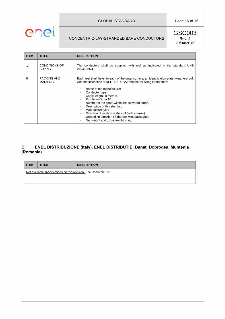
7 CONDITIONS OF SUPPLY
The conductors shall be supplied with reel as indicated in the standard UNE 21045:1974.
8
PACKING AND MARKING
Each reel shall have, in each of the outer surface, an identification plate, weatherproof, with the inscription “ENEL / ENDESA” and the following information:
• Name of the manufacturer • Conductor type • Cable length, in meters. • Purchase Order N° • Number of the spool within the delivered batch. • Description of this standard • Manufacture year • Direction of rotation of the coil (with a arrow). • Unwinding direction ( if the reel was packaged). • Net weight and gross weight in kg.
C ENEL DISTRIBUZIONE (Italy), ENEL DISTRIBUTIE: Banat, Dobrogea, Muntenia (Romania)
ITEM TITLE DESCRIPTION
Not available specifications on this revision. See Common List.
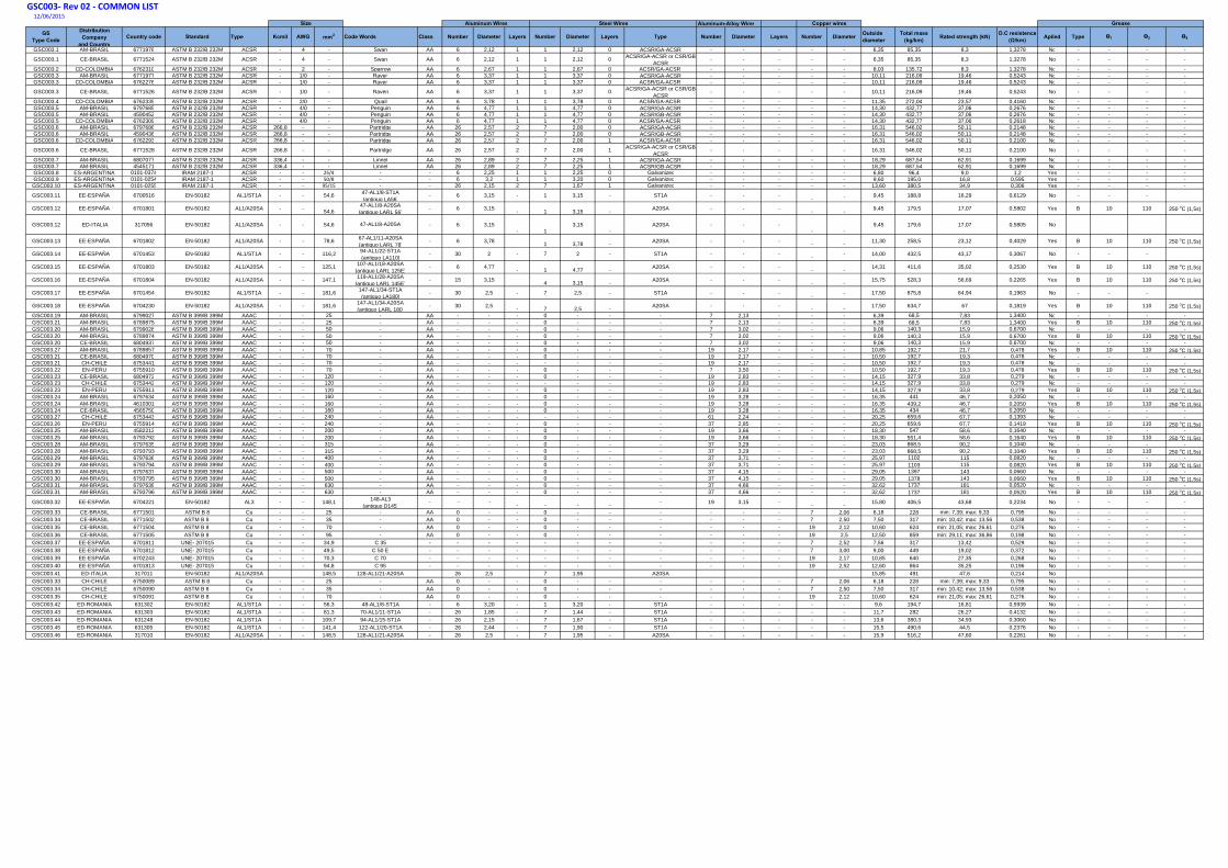
GSC003‐ Rev 02 ‐ COMMON LIST12/06/2015
Aluminum-Alloy Wires
GSType Code
Distribution Company
and CountryCountry code Standard Type Kcmil AWG mm2 Code Words Class Number Diameter Layers Number Diameter Layers Type Number Diameter Layers Number Diameter Outside
diameterTotal mass
(kg/km) Rated strength (kN) D.C resistence (Ω/km) Aplied Type Ɵ1 Ɵ2 Ɵ4
GSC003.1 AM-BRASIL 6771976 ASTM B 232/B 232M ACSR - 4 - Swan AA 6 2,12 1 1 2,12 0 ACSR/GA-ACSR - - - - - 6,35 85,35 8,3 1,3278 No - - - -
GSC003.1 CE-BRASIL 6771524 ASTM B 232/B 232M ACSR - 4 - Swan AA 6 2,12 1 1 2,12 0 ACSR/GA-ACSR or CSR/GB-ACSR
- - - - - 6,35 85,35 8,3 1,3278 No - - - -
GSC003.2 CD-COLOMBIA 6762310 ASTM B 232/B 232M ACSR - 2 - Sparrow AA 6 2,67 1 1 2,67 0 ACSR/GA-ACSR - - - - - 8,03 135,72 8,3 1,3278 No - - - -GSC003.3 AM-BRASIL 6771977 ASTM B 232/B 232M ACSR - 1/0 - Raven AA 6 3,37 1 1 3,37 0 ACSR/GA-ACSR - - - - - 10,11 216,09 19,46 0,5243 No - - - -GSC003.3 CD-COLOMBIA 6762276 ASTM B 232/B 232M ACSR - 1/0 - Raven AA 6 3,37 1 1 3,37 0 ACSR/GA-ACSR - - - - - 10,11 216,09 19,46 0,5243 No - - - -
GSC003.3 CE-BRASIL 6771526 ASTM B 232/B 232M ACSR - 1/0 - Raven AA 6 3,37 1 1 3,37 0 ACSR/GA-ACSR or CSR/GB-ACSR
- - - - - 10,11 216,09 19,46 0,5243 No - - - -
GSC003.4 CD-COLOMBIA 6762335 ASTM B 232/B 232M ACSR - 2/0 - Quail AA 6 3,78 1 1 3,78 0 ACSR/GA-ACSR - - - - - 11,35 272,04 23,57 0,4160 No - - - -GSC003.5 AM-BRASIL 6797685 ASTM B 232/B 232M ACSR - 4/0 - Penguin AA 6 4,77 1 1 4,77 0 ACSR/GA-ACSR - - - - - 14,30 432,77 37,06 0,2676 No - - - -GSC003.5 AM-BRASIL 4590452 ASTM B 232/B 232M ACSR - 4/0 - Penguin AA 6 4,77 1 1 4,77 0 ACSR/GB-ACSR - - - - - 14,30 432,77 37,06 0,2676 No - - - -GSC003.5 CD-COLOMBIA 6762309 ASTM B 232/B 232M ACSR - 4/0 - Penguin AA 6 4,77 1 1 4,77 0 ACSR/GA-ACSR - - - - - 14,30 432,77 37,06 0,2618 No - - - -GSC003.6 AM-BRASIL 6797686 ASTM B 232/B 232M ACSR 266,8 - - Partridge AA 26 2,57 2 7 2,00 0 ACSR/GA-ACSR - - - - - 16,31 546,02 50,11 0,2148 No - - - -GSC003.6 AM-BRASIL 4590436 ASTM B 232/B 232M ACSR 266,8 - - Partridge AA 26 2,57 2 7 2,00 0 ACSR/GB-ACSR - - - - - 16,31 546,02 50,11 0,2148 No - - - -GSC003.6 CD-COLOMBIA 6762293 ASTM B 232/B 232M ACSR 266,8 - - Partridge AA 26 2,57 2 7 2,00 1 ACSR/GA-ACSR - - - - - 16,31 546,02 50,11 0,2100 No - - - -
GSC003.6 CE-BRASIL 6771528 ASTM B 232/B 232M ACSR 266,8 - - Partridge AA 26 2,57 2 7 2,00 1 ACSR/GA-ACSR or CSR/GB-ACSR
- - - - - 16,31 546,02 50,11 0,2100 No - - - -
GSC003.7 AM-BRASIL 6807077 ASTM B 232/B 232M ACSR 336,4 - - Linnet AA 26 2,89 2 7 2,25 1 ACSR/GA-ACSR - - - - - 18,29 687,54 62,91 0,1699 No - - - -GSC003.7 AM-BRASIL 4545171 ASTM B 232/B 232M ACSR 336,4 - - Linnet AA 26 2,89 2 7 2,25 1 ACSR/GB-ACSR - - - - - 18,29 687,54 62,91 0,1699 No - - - -GSC003.8 ES-ARGENTINA 0101-0374 IRAM 2187-1 ACSR - - 25/4 - - 6 2,25 1 1 2,25 0 Galvanized - - - - - 6,80 96,4 9,0 1,2 Yes - - - -GSC003.9 ES-ARGENTINA 0101-0254 IRAM 2187-1 ACSR - - 50/8 - - 6 3,2 1 1 3,20 0 Galvanized - - - - - 9,60 195,0 16,8 0,595 Yes - - - -GSC003.10 ES-ARGENTINA 0101-0255 IRAM 2187-1 ACSR - - 95/15 - - 26 2,15 2 7 1,67 1 Galvanized - - - - - 13,60 380,5 34,9 0,306 Yes - - - -
GSC003.11 EE-ESPAÑA 6700516 EN-50182 AL1/ST1A - - 54,6 47-AL1/8-ST1A(antiguo LA56)
- 6 3,15 - 1 3,15 - ST1A - - - - . 9,45 188,8 16,29 0,6129 No - - -
GSC003.12 EE-ESPAÑA 6701801 EN-50182 AL1/A20SA - - 54,647-AL1/8-A20SA(antiguo LARL 56)
- 6 3,15 - 1 3,15 - A20SA - - - - - 9,45 179,5 17,07 0,5802 Yes B 10 110 250 oC (1,5s)
GSC003.12 ED-ITALIA 317056 EN-50182 AL1/A20SA - - 54,6 47-AL1/8-A20SA - 6 3,15- 1
3,15-
A20SA - - -- -
9,45 179,6 17,07 0,5805 No
GSC003.13 EE-ESPAÑA 6701802 EN-50182 AL1/A20SA - - 78,6 67-AL1/11-A20SA(antiguo LARL 78)
- 6 3,78 1 3,78 - A20SA - - - - - 11,30 258,5 23,12 0,4029 Yes B 10 110 250 oC (1,5s)
GSC003.14 EE-ESPAÑA 6701453 EN-50182 AL1/ST1A - - 116,2 94-AL1/22-ST1A(antiguo LA110)
- 30 2 - 7 2 - ST1A - - - - - 14,00 432,5 43,17 0,3067 No - - -
GSC003.15 EE-ESPAÑA 6701803 EN-50182 AL1/A20SA - - 125,1 107-AL1/18-A20SA(antiguo LARL 125E)
- 6 4,77 - 1 4,77 - A20SA - - - - - 14,31 411,6 35,02 0,2530 Yes B 10 110 250 oC (1,5s)
GSC003.16 EE-ESPAÑA 6701804 EN-50182 AL1/A20SA - - 147,1 119-AL1/28-A20SA(antiguo LARL 145E)
- 15 3,15 4 3,15 - A20SA - - - - - 15,75 528,3 56,69 0,2265 Yes B 10 110 250 oC (1,5s)
GSC003.17 EE-ESPAÑA 6701454 EN-50182 AL1/ST1A - - 181,6 147-AL1/34-ST1A(antiguo LA180)
- 30 2,5 - 7 2,5 - ST1A - - - - - 17,50 675,8 64,94 0,1963 No - - -
GSC003.18 EE-ESPAÑA 6704230 EN-50182 AL1/A20SA - - 181,6 147-AL1/34-A20SA(antiguo LARL 180)
- 30 2,5 - 7 2,5 - A20SA - - - - - 17,50 634,7 67 0,1819 Yes B 10 110 250 oC (1,5s)
GSC003.19 AM-BRASIL 6799027 ASTM B 399/B 399M AAAC - - 25 - AA - - - 0 - - - 7 2,13 - - - 6,39 68,5 7,83 1,3400 No - - - -GSC003.21 AM-BRASIL 6789875 ASTM B 399/B 399M AAAC - - 25 - AA - - - 0 - - - 7 2,13 - - - 6,39 68,5 7,83 1,3400 Yes B 10 110 250 oC (1,5s)GSC003.20 AM-BRASIL 6799028 ASTM B 399/B 399M AAAC - - 50 - AA - - - 0 - - - 7 3,02 - - - 9,06 140,3 15,9 0,6700 No - - - -GSC003.20 AM-BRASIL 6789874 ASTM B 399/B 399M AAAC - - 50 - AA - - - 0 - - - 7 3,02 - - - 9,06 140,3 15,9 0,6700 Yes B 10 110 250 oC (1,5s)GSC003.20 CE-BRASIL 6804937 ASTM B 399/B 399M AAAC - - 50 - AA - - - 0 - - - 7 3,02 - - - 9,06 140,3 15,9 0,6700 No - - - -GSC003.27 AM-BRASIL 6789857 ASTM B 399/B 399M AAAC - - 70 - AA - - - 0 - - - 19 2,17 - - - 10,85 192,7 21,7 0,478 Yes B 10 110 250 oC (1,5s)GSC003.21 CE-BRASIL 6804970 ASTM B 399/B 399M AAAC - - 70 - AA - - - 0 - - - 19 2,17 - - - 10,50 192,7 19,3 0,478 No - - - -GSC003.21 CH-CHILE 6753441 ASTM B 399/B 399M AAAC - - 70 - AA - - - - - - - 19 2,17 - - - 10,50 192,7 19,3 0,478 No - - - -GSC003.22 EN-PERU 6755910 ASTM B 399/B 399M AAAC - - 70 - AA - - - 0 - - - 7 3,50 - - - 10,50 192,7 19,3 0,478 Yes B 10 110 250 oC (1,5s)GSC003.23 CE-BRASIL 6804972 ASTM B 399/B 399M AAAC - - 120 - AA - - - 0 - - - 19 2,83 - - - 14,15 327,9 33,8 0,279 No - - - -GSC003.23 CH-CHILE 6753442 ASTM B 399/B 399M AAAC - - 120 - AA - - - - - - - 19 2,83 - - - 14,15 327,9 33,8 0,279 No - - - -GSC003.23 EN-PERU 6755911 ASTM B 399/B 399M AAAC - - 120 - AA - - - 0 - - - 19 2,83 - - - 14,15 327,9 33,8 0,279 Yes B 10 110 250 oC (1,5s)GSC003.24 AM-BRASIL 6797634 ASTM B 399/B 399M AAAC - - 160 - AA - - - 0 - - - 19 3,28 - - - 16,35 441 46,7 0,2050 No - - - -GSC003.24 AM-BRASIL 4610301 ASTM B 399/B 399M AAAC - - 160 - AA - - - 0 - - - 19 3,28 - - - 16,35 439,2 46,7 0,2050 Yes B 10 110 250 oC (1,5s)GSC003.24 CE-BRASIL 4565750 ASTM B 399/B 399M AAAC - - 160 - AA - - - 0 - - - 19 3,28 - - - 16,35 434 46,7 0,2050 No - - - -GSC003.27 CH-CHILE 6753443 ASTM B 399/B 399M AAAC - - 240 - AA - - - - - - - 61 2,24 - - - 20,25 659,6 67,7 0,1393 No - - - -GSC003.26 EN-PERU 6755914 ASTM B 399/B 399M AAAC - - 240 - AA - - - 0 - - - 37 2,85 - - - 20,25 659,6 67,7 0,1419 Yes B 10 110 250 oC (1,5s)GSC003.25 AM-BRASIL 4582212 ASTM B 399/B 399M AAAC - - 200 - AA - - - 0 - - - 19 3,66 - - - 18,30 547 58,6 0,1640 No - - - -GSC003.25 AM-BRASIL 6793792 ASTM B 399/B 399M AAAC - - 200 - AA - - - 0 - - - 19 3,66 - - - 18,30 551,4 58,6 0,1640 Yes B 10 110 250 oC (1,5s)GSC003.28 AM-BRASIL 6797635 ASTM B 399/B 399M AAAC - - 315 - AA - - - 0 - - - 37 3,29 - - - 23,03 868,5 90,2 0,1040 No - - - -GSC003.28 AM-BRASIL 6793793 ASTM B 399/B 399M AAAC - - 315 - AA - - - 0 - - - 37 3,29 - - - 23,03 868,5 90,2 0,1040 Yes B 10 110 250 oC (1,5s)GSC003.29 AM-BRASIL 6797636 ASTM B 399/B 399M AAAC - - 400 - AA - - - 0 - - - 37 3,71 - - - 25,97 1102 115 0,0820 No - - - -GSC003.29 AM-BRASIL 6793794 ASTM B 399/B 399M AAAC - - 400 - AA - - - 0 - - - 37 3,71 - - - 25,97 1103 115 0,0820 Yes B 10 110 250 oC (1,5s)GSC003.30 AM-BRASIL 6797637 ASTM B 399/B 399M AAAC - - 500 - AA - - - 0 - - - 37 4,15 - - - 29,05 1397 143 0,0660 No - - - -GSC003.30 AM-BRASIL 6793795 ASTM B 399/B 399M AAAC - - 500 - AA - - - 0 - - - 37 4,15 - - - 29,05 1378 143 0,0660 Yes B 10 110 250 oC (1,5s)GSC003.31 AM-BRASIL 6797638 ASTM B 399/B 399M AAAC - - 630 - AA - - - 0 - - - 37 4,66 - - - 32,62 1737 181 0,0520 No - - - -GSC003.31 AM-BRASIL 6793796 ASTM B 399/B 399M AAAC - - 630 - AA - - - 0 - - - 37 4,66 - - - 32,62 1737 181 0,0520 Yes B 10 110 250 oC (1,5s)
GSC003.32 EE-ESPAÑA 6704221 EN-50182 AL3 - - 148,1 148-AL3(antiguo D145)
- - - - - - - - 19 3,15 - - - 15,80 406,5 43,68 0,2234 No - - - -
GSC003.33 CE-BRASIL 6771501 ASTM B 8 Cu - - 25 - AA 0 - - 0 - - - - - - 7 2,06 6,18 228 min: 7,39; max: 9,33 0,795 No - - - -GSC003.34 CE-BRASIL 6771502 ASTM B 8 Cu - - 35 - AA 0 - - 0 - - - - - - 7 2,50 7,50 317 min: 10,42; max: 13,56 0,538 No - - - -GSC003.35 CE-BRASIL 6771504 ASTM B 8 Cu - - 70 - AA 0 - - 0 - - - - - - 19 2,12 10,60 624 min: 21,05; max: 26,61 0,276 No - - - -GSC003.36 CE-BRASIL 6771505 ASTM B 8 Cu - - 95 - AA 0 - - 0 - - - - - - 19 2,5 12,50 859 min: 29,11; max: 36,86 0,198 No - - - -GSC003.37 EE-ESPAÑA 6701811 UNE- 207015 Cu - - 34,9 C 35 - - - - - - - - - - - 7 2,52 7,56 317 13,42 0,529 No - - - -GSC003.38 EE-ESPAÑA 6701812 UNE- 207015 Cu - - 49,5 C 50 E - - - - - - - - - - - 7 3,00 9,00 449 19,02 0,372 No - - - -GSC003.39 EE-ESPAÑA 6702243 UNE- 207015 Cu - - 70,3 C 70 - - - - - - - - - - - 19 2,17 10,85 640 27,35 0,268 No - - - -GSC003.40 EE-ESPAÑA 6701813 UNE- 207015 Cu - - 94,8 C 95 - - - - - - - - - - - 19 2,52 12,60 864 35,25 0,196 No - - - -GSC003.41 ED-ITALIA 317011 EN-50182 AL1/A20SA 148,5 128-AL1/21-A20SA 26 2,5 7 1,95 A20SA 15,85 491 47,6 0,214 NoGSC003.33 CH-CHILE 6750089 ASTM B 8 Cu - - 25 - AA 0 - - 0 - - - - - - 7 2,06 6,18 228 min: 7,39; max: 9,33 0,795 No - - - -GSC003.34 CH-CHILE 6750090 ASTM B 8 Cu - - 35 - AA 0 - - 0 - - - - - - 7 2,50 7,50 317 min: 10,42; max: 13,56 0,538 No - - - -GSC003.35 CH-CHILE 6750091 ASTM B 8 Cu - - 70 - AA 0 - - 0 - - - - - - 19 2,12 10,60 624 min: 21,05; max: 26,61 0,276 No - - - -GSC003.42 ED-ROMANIA 631302 EN-50182 AL1/ST1A - - 56,3 48-AL1/8-ST1A - 6 3,20 - 1 3,20 - ST1A - - - - - 9,6 194,7 16,81 0,5939 No - - - -GSC003.43 ED-ROMANIA 631303 EN-50182 AL1/ST1A - - 81,3 70-AL1/11-ST1A - 26 1,85 - 7 1,44 - ST1A - - - - - 11,7 282 26,27 0,4132 No - - - -GSC003.44 ED-ROMANIA 631248 EN-50182 AL1/ST1A - - 109,7 94-AL1/15-ST1A - 26 2,15 - 7 1,67 - ST1A - - - - - 13,6 380,3 34,93 0,3060 No - - - -GSC003.45 ED-ROMANIA 631305 EN-50182 AL1/ST1A - - 141,4 122-AL1/20-ST1A - 26 2,44 - 7 1,90 - ST1A - - - - - 15,5 490,6 44,5 0,2376 No - - - -GSC003.46 ED-ROMANIA 317010 EN-50182 AL1/A20SA - - 148,5 128-AL1/21-A20SA - 26 2,5 - 7 1,95 - A20SA - - - - - 15,9 516,2 47,60 0,2261 No - - - -
GreaseSize Aluminum Wires Steel Wires Copper wires