Embed Size (px)
Citation preview
Axis Digital concealed installation instuctions page 1
Axis®
DigitalConcealed standard and pumped
The Waste Electrical and Electronic Equipment (Producer Responsibility) Regulation 2004
This product is outside the scope of the European Waste Electrical and Electronic Equipment Directive as interpreted within the UK.
In the UK this product can therefore be disposed of through commercial non-WEEE waste facilities.
The original manufacturer does not accept any liability under the WEEE directive.
Axis Digital concealed installation instuctions page 2
Shower systems
Axis Digital concealed standard
With Axis wall
mounted fixed head
AX8120
With Axis ceiling mounted fixed head
AX8130
With Axis adjustable
height head
AX8110
With Axis wall
mounted fixed head
AX8125
With Axis ceiling mounted fixed head
AX8135
With Axis adjustable
height head
AX8115
Axis Digital concealed pumped
Axis Digital concealed installation instuctions page 3
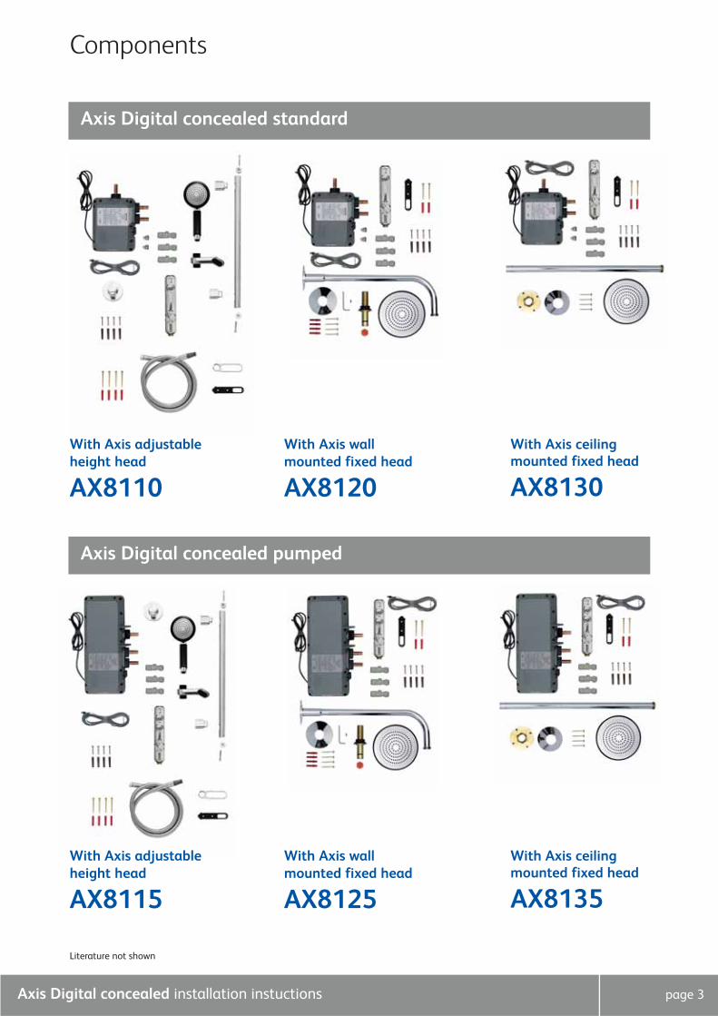
Components
Literature not shown
Axis Digital concealed standard
With Axis wall
mounted fixed head
AX8120
With Axis ceiling mounted fixed head
AX8130
With Axis adjustable
height head
AX8110
Axis Digital concealed pumped
With Axis wall
mounted fixed head
AX8125
With Axis ceiling mounted fixed head
AX8135
With Axis adjustable
height head
AX8115
Axis Digital concealed installation instuctions page 4
Important information
Safety informationThis product must be installed by a competent person in accordance with all relevant Water and Wiring Supply Regulations.
Electrical supply and bonding of the bathroom must comply with the current IEE regulations, and your attention is drawn to
the requirements concerning protective earth bonding.
The water circuit should be installed so that other taps or appliances operated elsewhere within the premises do not
significantly affect the flow.
This shower must not be used with a hot water supply temperature of over 65˚c.
The Digital processor must not be installed in situations where the ambient temperature is likely to exceed 40˚c.
The control must not be installed in situations where the ambient temperature is likely to fall below 5˚c or rise above 70˚c.
We do not recommend the use of Axis Digital in steam therapy facilities.
This appliance must be earthed.
Cables which are chased into the wall must be protected by the use of conduit or sheathing.
Surface mounted cables must also be protected by a suitable approved conduit.
The power lead must only be replaced by the manufacturer or his accredited service agent.
The user control is supplied from a safety extra low voltage source.
This product is suitable for household use only.
SPECIAL NOTES FOR INSTALLATION OF DIGITAL PUMPED PROCESSOR
1) The Axis Digital pumped shower system is designed to operate up to a maximum static pressure of 1 bar (14.5 psi).
2) Under no circumstances must the pumped processor be connected directly to the water main or in line with another booster pump.
3) The minimum actual capacity of the cold water storage cistern should be not less than 225 litres (50 gallons). The capacity
of the hot water cylinder must be capable of meeting the anticipated demand.
SPECIAL NOTES FOR INSTALLATION OF DIGITAL STANDARD PROCESSOR
Pressures: The Axis Digital shower system is designed to operate up to a maximum static pressure of 7 bar (100psi). Where
pressures are likely to exceed 7 bar (100psi), a pressure reducing valve must be fitted to the incoming mains supply. A setting
of 4 bar (60psi) is recommended. It should be noted that daytime pressures approaching 6 bar (80psi) can rise above the
stated maximum overnight.
COMBINATION BOILER SYSTEMS:
The appliance must have a minimum domestic hot water rating of 80,000 BTU (23.4kW) and be of the type fitted with a fully
modulating gas valve.
The flow switch on the combi boiler needs to flow a minimum of 3 litres per minute. If in any doubt please contact the
appliance manufacturer before installation commences.
PLEASE NOTE: INLET TEMPERATURE CHANGE MAY CAUSE THE DIGITAL CONTROLLER TO FLASH.
THIS IS NOT NECESSARILY CHANGING THE OUTLET TEMPERATURE.
ConnectionsThis product incorporates ‘push-fit’ type connections. Tube should be cut using a rotary type cutter and lubricated using a
silicone-based lubricant or petroleum jelly (Vaseline or similar) prior to insertion into the fitting.
THESE FITTINGS ARE NOT SUITABLE FOR STAINLESS STEEL TUBE.
FlushingSome modern fluxes can be extremely corrosive and, if left in contact, will attack the working parts of this unit. All soldering
must be completed and the pipework thoroughly flushed out in accordance with Water Supply Regulations prior to connection
of the product.
After installationRun through the system operation with the purchaser and hand them this guide. Complete and post the Axis guarantee card.
Axis Digital concealed installation instuctions page 5
Step-by-step instructions
In addition to the guide below it is essential that the written instructions
opposite are read and understood and that you have all the necessary
components (shown above) before commencing installation. Failure to install
the product in accordance with these instructions may adversely affect the
warranty terms and conditions. Do not undertake any part of this installation
unless you are competent to do so. Prior to starting ensure that you are
familiar with the necessary plumbing regulations required to install the
product correctly and safely.
!
The Axis Digital shower system is supplied with masonry fixings intended for
use with a wall of solid construction. If the unit is to be installed on a wall of
a different construction then please use alternative fixings as required.
!
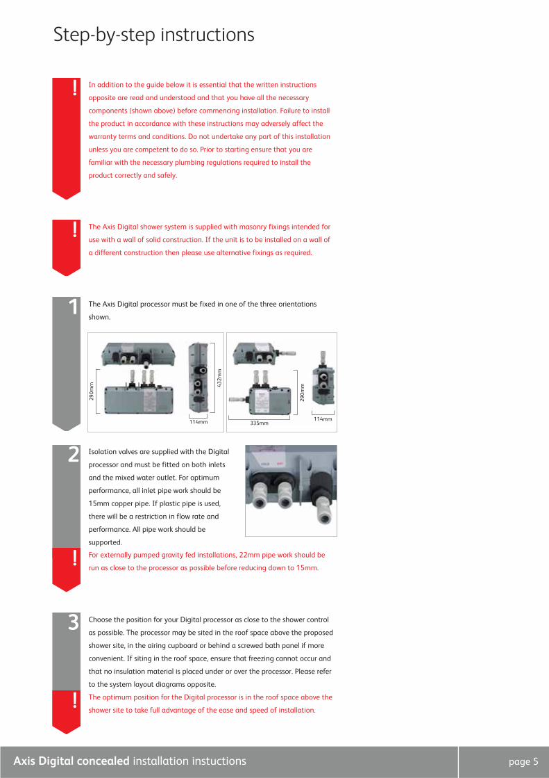
The Axis Digital processor must be fixed in one of the three orientations
shown.1
114mm
432m
m
290m
m
335mm
290m
m
114mm
Choose the position for your Digital processor as close to the shower control
as possible. The processor may be sited in the roof space above the proposed
shower site, in the airing cupboard or behind a screwed bath panel if more
convenient. If siting in the roof space, ensure that freezing cannot occur and
that no insulation material is placed under or over the processor. Please refer
to the system layout diagrams opposite.
3
Isolation valves are supplied with the Digital
processor and must be fitted on both inlets
and the mixed water outlet. For optimum
performance, all inlet pipe work should be
15mm copper pipe. If plastic pipe is used,
there will be a restriction in flow rate and
performance. All pipe work should be
supported.
2
For externally pumped gravity fed installations, 22mm pipe work should be
run as close to the processor as possible before reducing down to 15mm. !
! The optimum position for the Digital processor is in the roof space above the
shower site to take full advantage of the ease and speed of installation.
Axis Digital concealed installation instuctions page 6
Choose the position for your Digital processor as close to the shower control
as possible. The processor may be sited in the roof space above the proposed
shower site, in the airing cupboard or behind a screwed bath panel if more
convenient. If siting in the roof space, ensure that freezing cannot occur and
that no insulation material is placed under or over the processor. Please refer
to the system layout diagrams opposite.
3
! The distance between the processor and shower control must be within range
of the data cable supplied (7m). A 10m cable is available on request.
The processor must be sited in a position so that access can be gained for
testing and service purposes.
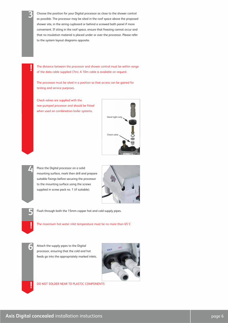
Check valves are supplied with the
non-pumped processor and should be fitted
when used on combination boiler systems.
Place the Digital processor on a solid
mounting surface, mark then drill and prepare
suitable fixings before securing the processor
to the mounting surface using the screws
supplied in screw pack no. 1 (if suitable).
4
Flush through both the 15mm copper hot and cold supply pipes.5The maximum hot water inlet temperature must be no more than 65˚C!
Attach the supply pipes to the Digital
processor, ensuring that the cold and hot
feeds go into the appropriately marked inlets.
6
DO NOT SOLDER NEAR TO PLASTIC COMPONENTS!
Check valve
Hand tight only
Axis Digital concealed installation instuctions page 7
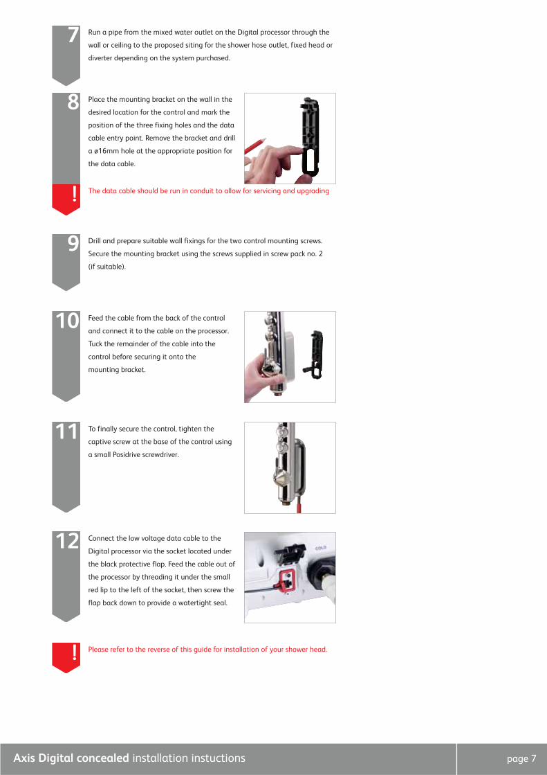
Run a pipe from the mixed water outlet on the Digital processor through the
wall or ceiling to the proposed siting for the shower hose outlet, fixed head or
diverter depending on the system purchased.
7
Feed the cable from the back of the control
and connect it to the cable on the processor.
Tuck the remainder of the cable into the
control before securing it onto the
mounting bracket.
10
Place the mounting bracket on the wall in the
desired location for the control and mark the
position of the three fixing holes and the data
cable entry point. Remove the bracket and drill
a ø16mm hole at the appropriate position for
the data cable.
8
The data cable should be run in conduit to allow for servicing and upgrading!
Drill and prepare suitable wall fixings for the two control mounting screws.
Secure the mounting bracket using the screws supplied in screw pack no. 2
(if suitable).
9
To finally secure the control, tighten the
captive screw at the base of the control using
a small Posidrive screwdriver.
11
Connect the low voltage data cable to the
Digital processor via the socket located under
the black protective flap. Feed the cable out of
the processor by threading it under the small
red lip to the left of the socket, then screw the
flap back down to provide a watertight seal.
12
Please refer to the reverse of this guide for installation of your shower head.!
Axis Digital concealed installation instuctions page 8
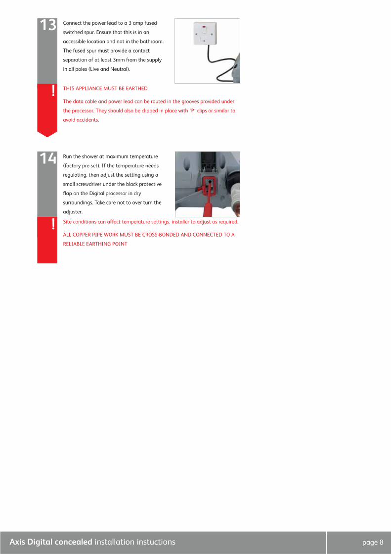
Connect the power lead to a 3 amp fused
switched spur. Ensure that this is in an
accessible location and not in the bathroom.
The fused spur must provide a contact
separation of at least 3mm from the supply
in all poles (Live and Neutral).
13
THIS APPLIANCE MUST BE EARTHED
The data cable and power lead can be routed in the grooves provided under
the processor. They should also be clipped in place with ‘P’ clips or similar to
avoid accidents.
!
Run the shower at maximum temperature
(factory pre-set). If the temperature needs
regulating, then adjust the setting using a
small screwdriver under the black protective
flap on the Digital processor in dry
surroundings. Take care not to over turn the
adjuster.
14
Site conditions can affect temperature settings, installer to adjust as required.
ALL COPPER PIPE WORK MUST BE CROSS-BONDED AND CONNECTED TO A
RELIABLE EARTHING POINT
!
Axis Digital concealed installation instuctions page 9
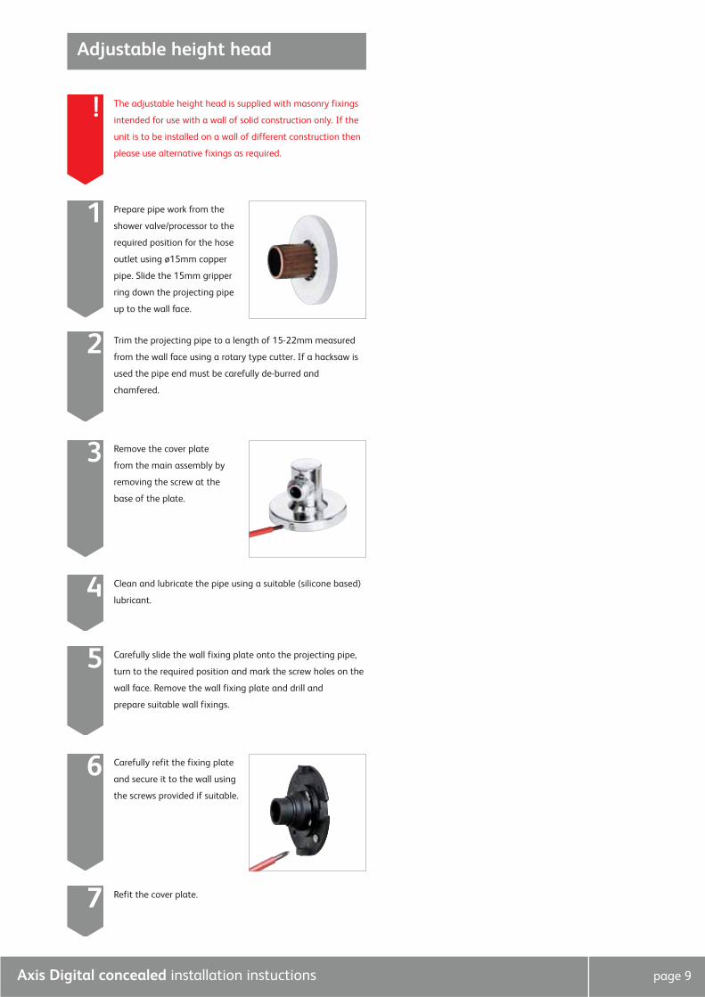
Adjustable height head
The adjustable height head is supplied with masonry fixings
intended for use with a wall of solid construction only. If the
unit is to be installed on a wall of different construction then
please use alternative fixings as required.
!
Prepare pipe work from the
shower valve/processor to the
required position for the hose
outlet using ø15mm copper
pipe. Slide the 15mm gripper
ring down the projecting pipe
up to the wall face.
1
Trim the projecting pipe to a length of 15-22mm measured
from the wall face using a rotary type cutter. If a hacksaw is
used the pipe end must be carefully de-burred and
chamfered.
2
Remove the cover plate
from the main assembly by
removing the screw at the
base of the plate.
3
Clean and lubricate the pipe using a suitable (silicone based)
lubricant.4
Carefully slide the wall fixing plate onto the projecting pipe,
turn to the required position and mark the screw holes on the
wall face. Remove the wall fixing plate and drill and
prepare suitable wall fixings.
5
Carefully refit the fixing plate
and secure it to the wall using
the screws provided if suitable.
6
Refit the cover plate.7
Axis Digital concealed installation instuctions page 10
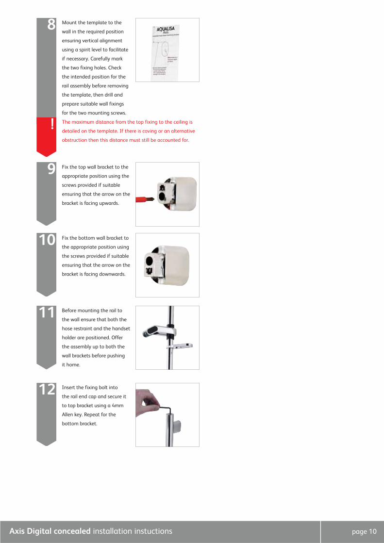
Mount the template to the
wall in the required position
ensuring vertical alignment
using a spirit level to facilitate
if necessary. Carefully mark
the two fixing holes. Check
the intended position for the
rail assembly before removing
the template, then drill and
prepare suitable wall fixings
for the two mounting screws.
8
The maximum distance from the top fixing to the ceiling is
detailed on the template. If there is coving or an alternative
obstruction then this distance must still be accounted for.
!
Fix the top wall bracket to the
appropriate position using the
screws provided if suitable
ensuring that the arrow on the
bracket is facing upwards.
9
Fix the bottom wall bracket to
the appropriate position using
the screws provided if suitable
ensuring that the arrow on the
bracket is facing downwards.
10
Before mounting the rail to
the wall ensure that both the
hose restraint and the handset
holder are positioned. Offer
the assembly up to both the
wall brackets before pushing
it home.
11
Insert the fixing bolt into
the rail end cap and secure it
to top bracket using a 4mm
Allen key. Repeat for the
bottom bracket.
12
Axis Digital concealed installation instuctions page 11
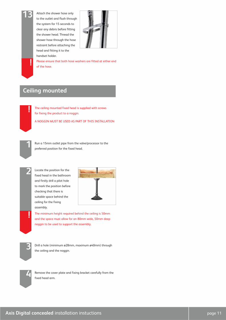
Attach the shower hose only
to the outlet and flush through
the system for 15 seconds to
clear any debris before fitting
the shower head. Thread the
shower hose through the hose
restraint before attaching the
head and fitting it to the
handset holder.
13
Please ensure that both hose washers are fitted at either end
of the hose.!
Ceiling mounted
The ceiling mounted fixed head is supplied with screws
for fixing the product to a noggin.
A NOGGIN MUST BE USED AS PART OF THIS INSTALLATION
!
Run a 15mm outlet pipe from the valve/processor to the
preferred position for the fixed head.1
Locate the position for the
fixed head in the bathroom
and firstly drill a pilot hole
to mark the position before
checking that there is
suitable space behind the
ceiling for the fixing
assembly.
2
The minimum height required behind the ceiling is 50mm
and the space must allow for an 80mm wide, 50mm deep
noggin to be used to support the assembly.
!
Drill a hole (minimum ø28mm, maximum ø40mm) through
the ceiling and the noggin.3
Remove the cover plate and fixing bracket carefully from the
fixed head arm.4

Axis Digital concealed installation instuctions page 12
Set the fixing bracket into
position and mark the fixing
points. Remove the bracket
and drill and prepare
suitable fixings. Refit the
fixing bracket and secure it
through the ceiling and into
the noggin using the screws
provided if suitable.
5
Refit the cover plate onto
the fixed head arm and feed
it through the fixing bracket
to the correct depth.
Tighten the nut using a
32mm spanner if necessary
to facilitate.
6
Cut off the excess pipe allowing for a suitable working length
to allow for the required connection. If a push fit connector
is to be used then the pipe must be abraded to remove all
chrome plating.
7
Connect the pipe work from the valve to the pipe end for the
fixed head using a suitable coupling. Fully tighten the nut
on the ceiling mounting bracket using a 32mm spanner if
necessary to facilitate.
8
Run the shower for a few seconds to clear any debris and
to check for any leaks.!
Carefully slide the cover
plate back over the fixed
head arm and into position
against the ceiling.
9
Secure the shower head
tightly to the fixed head
arm using a 28mm spanner
to facilitate tightening.
Check the installation for
leaks then fit the badge to
the front of the spray plate.
10
Axis Digital concealed installation instuctions page 13
Ceiling flush mounted
The ceiling flush mounted fixed head is supplied with screws
for fixing the product to a noggin.
A NOGGIN MUST BE USED AS PART OF THIS INSTALLATION
Before starting installation of the flush mounted fixed head
it is imperative that the installation notes below are read and
understood and that checks are made to ensure that there
is sufficient space behind the ceiling as required.
!
Run a 15mm outlet pipe from the shower valve/processor
to the preferred position for the fixed head. Ensure that the
outlet is clear from debris.
1
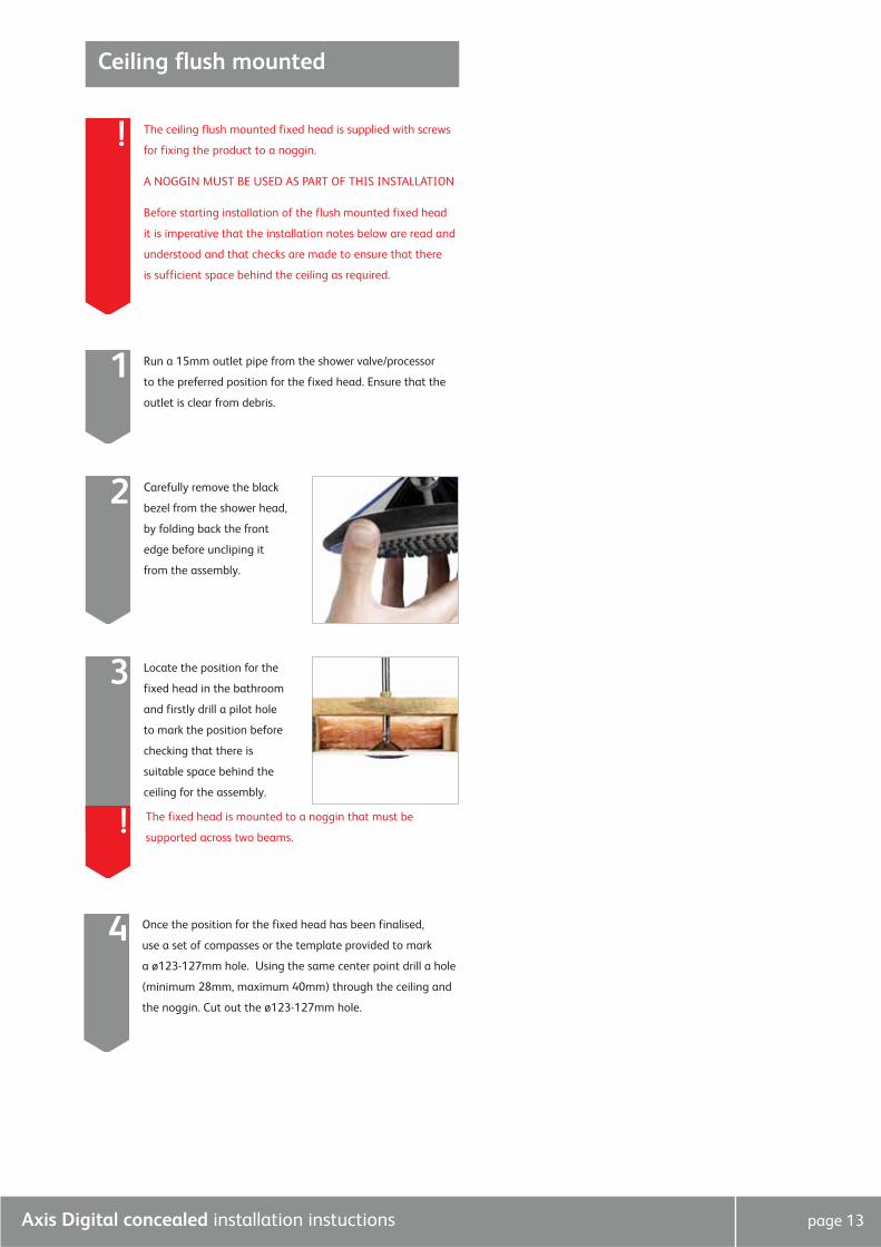
Carefully remove the black
bezel from the shower head,
by folding back the front
edge before uncliping it
from the assembly.
2
3
The fixed head is mounted to a noggin that must be
supported across two beams. !
Once the position for the fixed head has been finalised,
use a set of compasses or the template provided to mark
a ø123-127mm hole. Using the same center point drill a hole
(minimum 28mm, maximum 40mm) through the ceiling and
the noggin. Cut out the ø123-127mm hole.
4
Locate the position for the
fixed head in the bathroom
and firstly drill a pilot hole
to mark the position before
checking that there is
suitable space behind the
ceiling for the assembly.
page 14
Remove the cover plate and fixing bracket carefully from the
fixed head arm.5
Set the fixing bracket into
position (above the noggin)
and mark the fixing points.
Remove the bracket and drill
and prepare suitable fixings.
Refit the fixing bracket and
secure it to the noggin using
the screws provided if
suitable.
6
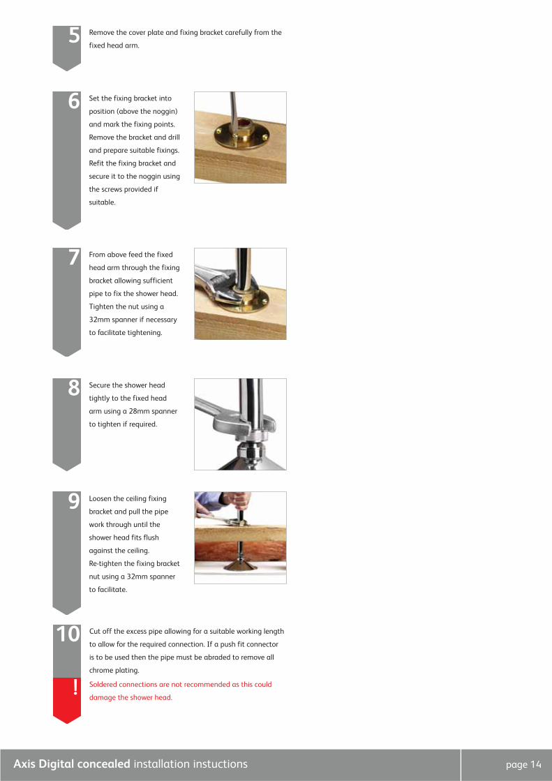
From above feed the fixed
head arm through the fixing
bracket allowing sufficient
pipe to fix the shower head.
Tighten the nut using a
32mm spanner if necessary
to facilitate tightening.
7
Secure the shower head
tightly to the fixed head
arm using a 28mm spanner
to tighten if required.
8
Loosen the ceiling fixing
bracket and pull the pipe
work through until the
shower head fits flush
against the ceiling.
Re-tighten the fixing bracket
nut using a 32mm spanner
to facilitate.
9
Cut off the excess pipe allowing for a suitable working length
to allow for the required connection. If a push fit connector
is to be used then the pipe must be abraded to remove all
chrome plating.
10
Soldered connections are not recommended as this could
damage the shower head.!
Axis Digital concealed installation instuctions
Axis Digital concealed installation instuctions page 15
Connect the pipe work from the valve to the pipe work for
the fixed head. Check that the shower head is still in the
correct position before fully tightening the nut on the ceiling
mounting bracket using a 32mm spanner.
11
Check the installation for leaks then fit the badge to the front
of the spray plate.12
Wall mounted
The wall mounted fixed head is supplied with masonry
fixings intended for use with a wall of solid construction only.
If the unit is to be installed on a wall of different construction
then please use alternative fixings as required.
The maximum panel thickness for installation of the fixed
shower head is 35mm, this includes a maximum tile thickness
of 15mm.
!
Run a 15mm outlet pipe from the shower valve/processor to
the preferred position for the fixed head arm, the pipe must
terminate with a suitable 1/2” BSP female fitting.
1
If the spigot cannot to be secured to the wall then the pipe
must be secured using a clip or another form of fixing.!
2
If the spigot is to be secured before tiling then the depth of
the tiles must be taken into consideration. !
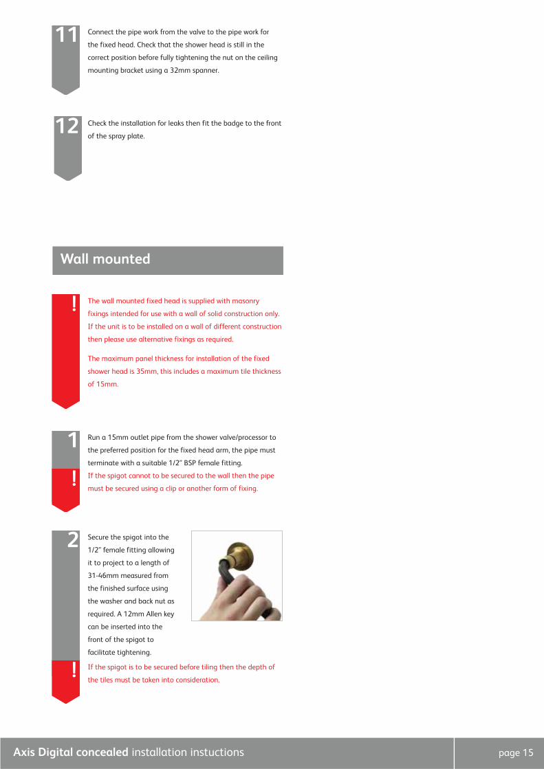
Secure the spigot into the
1/2” female fitting allowing
it to project to a length of
31-46mm measured from
the finished surface using
the washer and back nut as
required. A 12mm Allen key
can be inserted into the
front of the spigot to
facilitate tightening.
Axis Digital concealed installation instuctions page 16
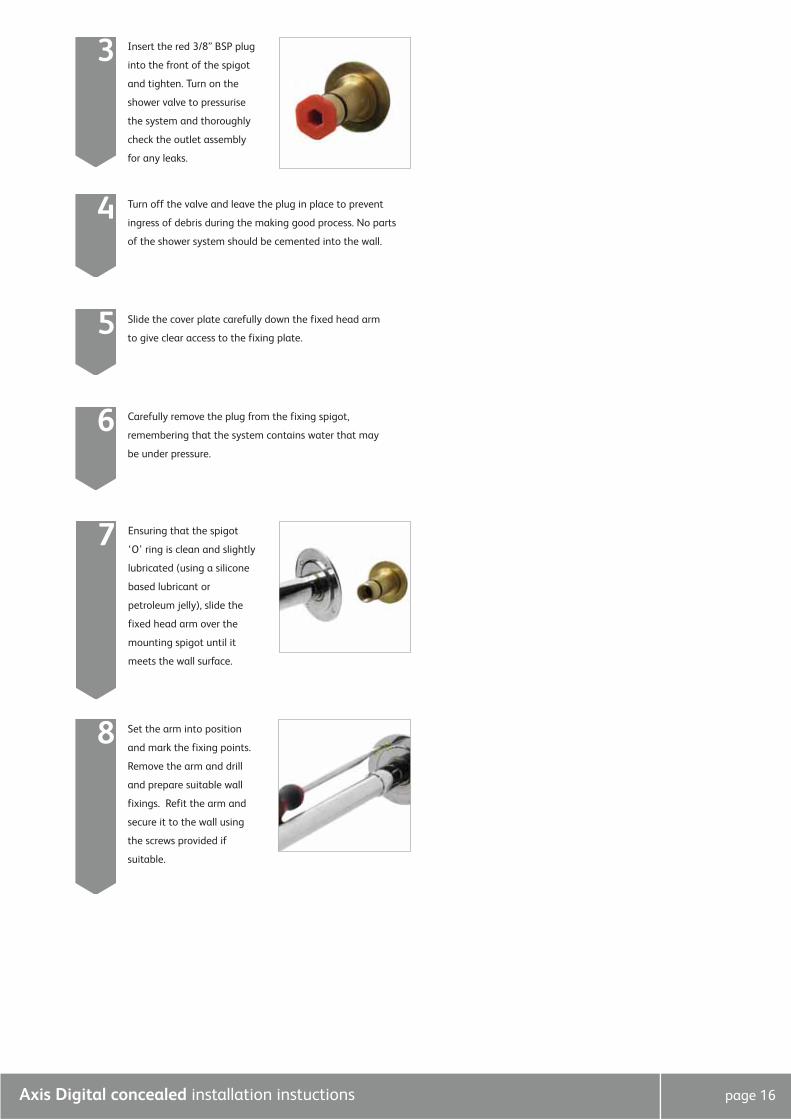
Insert the red 3/8” BSP plug
into the front of the spigot
and tighten. Turn on the
shower valve to pressurise
the system and thoroughly
check the outlet assembly
for any leaks.
3
Ensuring that the spigot
‘O’ ring is clean and slightly
lubricated (using a silicone
based lubricant or
petroleum jelly), slide the
fixed head arm over the
mounting spigot until it
meets the wall surface.
7
Turn off the valve and leave the plug in place to prevent
ingress of debris during the making good process. No parts
of the shower system should be cemented into the wall.
4
Slide the cover plate carefully down the fixed head arm
to give clear access to the fixing plate.5
Carefully remove the plug from the fixing spigot,
remembering that the system contains water that may
be under pressure.
6
Set the arm into position
and mark the fixing points.
Remove the arm and drill
and prepare suitable wall
fixings. Refit the arm and
secure it to the wall using
the screws provided if
suitable.
8
Axis Digital concealed installation instuctions page 17
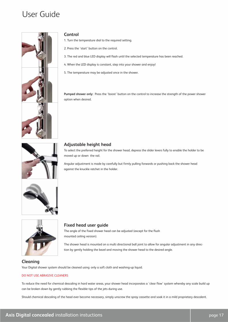
Control1. Turn the temperature dial to the required setting.
2. Press the ‘start’ button on the control.
3. The red and blue LED display will flash until the selected temperature has been reached.
4. When the LED display is constant, step into your shower and enjoy!
5. The temperature may be adjusted once in the shower.
Pumped shower only: Press the ‘boost’ button on the control to increase the strength of the power shower
option when desired.
Adjustable height headTo select the preferred height for the shower head, depress the slider levers fully to enable the holder to be
moved up or down the rail.
Angular adjustment is made by carefully but firmly pulling forwards or pushing back the shower head
against the knuckle ratchet in the holder.
Fixed head user guideThe angle of the fixed shower head can be adjusted (except for the flush
mounted ceiling version).
The shower head is mounted on a multi directional ball joint to allow for angular adjustment in any direc-
tion by gently holding the bezel and moving the shower head to the desired angle.
User Guide
CleaningYour Digital shower system should be cleaned using only a soft cloth and washing-up liquid.
DO NOT USE ABRASIVE CLEANERS
To reduce the need for chemical descaling in hard water areas, your shower head incorporates a ‘clear flow’ system whereby any scale build up
can be broken down by gently rubbing the flexible tips of the jets during use.
Should chemical descaling of the head ever become necessary, simply unscrew the spray cassette and soak it in a mild proprietary descalent.
Axis Digital concealed installation instuctions page 18
Hot water cylinder
Supply
Vent and draw-offpipe to hot water
Connect‘A’ or ‘B’
Cold feedto cylinder
B
A
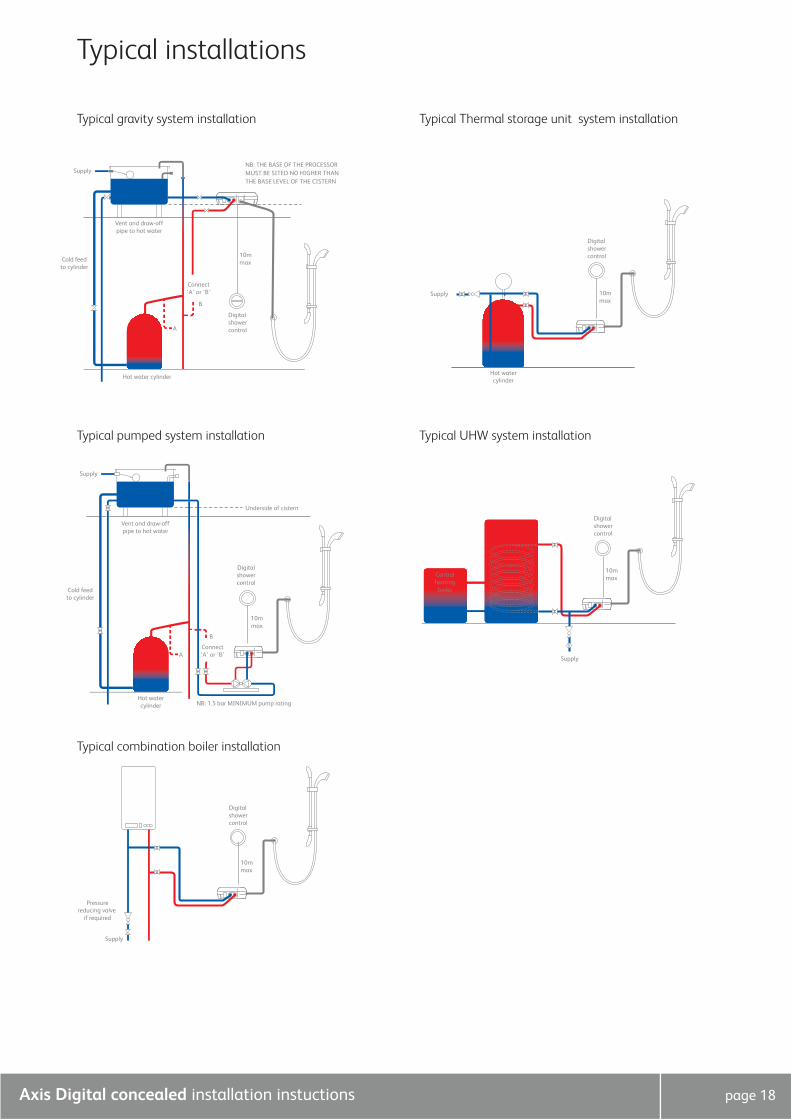
NB: THE BASE OF THE PROCESSOR MUST BE SITED NO HIGHER THAN THE BASE LEVEL OF THE CISTERN
10mmax
Digitalshowercontrol
Supply
Pressurereducing valve
if required
10mmax
Digitalshowercontrol
Supply
Hot watercylinder
10mmax
Digitalshowercontrol
10mmax
Digitalshowercontrol
Centralheatingboiler
Supply
Supply
Vent and draw-offpipe to hot water
Underside of cistern
Hot watercylinder NB: 1.5 bar MINIMUM pump rating
Cold feedto cylinder
Connect‘A’ or ‘B’
B
A
10mmax
Digitalshowercontrol
Typical installations
Typical gravity system installation
Typical pumped system installation Typical UHW system installation
Typical Thermal storage unit system installation
Typical combination boiler installation
Aqualisa Products Limited
The Flyer’s Way
Westerham Kent TN16 1DE
Sales enquiries: 01959 560010
Republic of Ireland 01-864-3363
Customer helpline: 01959 560010
Republic of Ireland 01-844-3212
Brochure Hotline: 0800 652 3669
Website: www.aqualisa.co.uk
Email: [email protected]
Please note that calls may be recorded for training and quality purposes
The company reserves the right to alter, change or modify the product specifications without prior warning
® Registered Trademark Aqualisa Products Limited