Embed Size (px)
Citation preview
- C.ON
NAVAL POSTGRADUATE SCHOOLMonterey California
N
DTI
ELJECTIEJUN 0 1 t90
. .THESIS
RAPID PROTOTYPING:A SURVEY AND EVALUATION OFMETHODOLOGIES AND MODELS
by
Harrison Douglas Fountain
March 1990
Thesis Advisor: Luqi
Approved for public release; distribution is unlimited.
BESTAVAILABLE COPY
900 0 at 4 0
UNCLASSIFIEDSECURITY CLASSIFICATION OF THIS PAGE
REPORT DOCUMENTATION PAGE1. REPORT SECURITY CLASSIFICATION UNCLASSIFIED lb. RESTRICTIVE MARKINGS
2a SECURITY CLASSIFICATION AUTHORITY 3. DISTRIBUTIONAVAILABILITY OF REPORT
2b. DECLASSIFICATION/DOWNGRADING SCHEDULE Approved for public release;distribution is unlimited
4. PERFORMING ORGANIZATION REPORT NUMBER(S) 5. MONITORING ORGANIZATION REPORT NUMBER(S)
61L NAME OF PERfFORMING ORGANIZATION 6b. OFFICE SYMBOL 7. NAPE OF MONITOriNG ORGANIZATIONComputer Science Dept. (if aokae) Naval Postgraduate SchoolNaval Postgraduate School 52
6c. ADDRESS (City, State, and ZIP Code) 7b. ADDRESS (City, State, and ZIP Code)
Monterey, CA 93943-5000 Monterey, CA 93943-5000
8a. NAME OF FUNDING/SPONSORING 8b. OFFICE SYMBOL 9. PROCUREMENT INSTRUMENT IDENTIFICATION NUMBERORGANIZATION (if appcable)
8c. ADDRESS (Ciy, State, and ZIP Code) 10. SOURCE OF FUNDING NUMBERSPROGRAM PROJECT TASK WORK UNITELEMENT NO. NO. NO. ACCESSION NO.
11. TITLE (Include Secunty Classification)RAPID PROTOTYPING: A SURVEY AND EVALUATION OF METHODOLOGIES AND MODELS
12. PERSONAL AUTHOR(S)Fountain, Harrison Douglas
13a. TYPE OF REPORT 13b. TIME COVERED 14. DATE OF REPORT (Year, Month, Day) 15 PAGF COUNTMaster's Thesis I FROM 05/89 TO 03/90 March 1990 165
16. SUPPLEMENTARY NOTATION The views expressed in this thesis are those of the author and do not reflectI the official policy or position of the Department of Defense or the United States Government.
1 . COSATI CODES 18. SUBJECT TERMS (Continue on reverse if necessary and identify by block number)
FIELD GROUP SUB-GROUP rapid prototyping, prototyping support system environment, life cyclemodel, paradigm, methodologies, models, DoD Software Goals
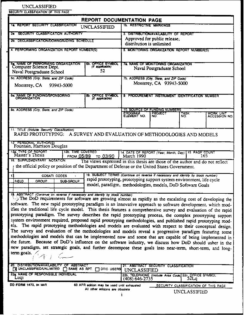
11. ABSTRACT (Continue on reverse if necessary and identify by block number)-) The DoD requirements for software are growing almost as rapidly as the escalating cost of developing the
software. The new rapid prototyping paradigm is an innovative approach to software development, which mod-ifies the traditional life cycle model. This thesis features a comprehensive survey and evaluation of the rapidprototyping paradigm. The survey describes the rapid prototyping process, the complex prototyping supportsystem environment required, proposed rapid prototyping methodologies, and published rapid prototyping mod-els. The rapid prototyping methodologies and models are evaluated with respect to their conceptual design.The survey and evaluation of the methodologies and models reveal a progressive paradigm featuring somemethodologies and models that can be implemented now and some that are capable of being implemented inthe future. Because of DoD's influence on the software industry, we discuss how DoD should usher in thenew paradigm, set strategic goals, and further decompose these goals into near-term, short-term, and long-term goals. , .,
0. DISTRIBUTIONWAVAILABIUTY OF ABSTRACT 2. ABS TC SECURTY CLAS~IFICATION___[] UNCLASSIFIEDUNLIMITED Q SAME AS RPT. [] DTIC USERS UNCLASSIFIED
22.qiNAME OF RESPONSIBLE INDIVIDUAL 22b. TELEPHONE (Include Area Code 22c.20FFICE SYMBOLLuqi (408) 646-2735 52Lq00 FORM 1473, 84 MAR 83 APR edtion may be used until exhausted SECURITY CLASSIFICATION OF THIS PAGE
All other editions are obsolete UNCLASSIFIEDi UCASFE
Approved for public release; distribution is unlimited
RAPID PROTOTYPINGA SURVEY AND EVALUATION OFMETHODOLOGIES AND MODELS
byHarrison Douglas Fountain
Captain, United States ArmyB.S.W., San Francisco State University, 1981
Submitted in partial fulfillment of therequirements f.,r the degree of
MASTER OF COMPUTER SCIENCE
from the
NAVAL POSTGRADUATE SCHOOL@ March 1990 .
Author: / "Harrison Dou Ps Fountain "
Approved By: _A__
Luqi, Thesi Advisor
LCDR Rachel Griffin, Second Reader
Robert B. McGhee, Chairman,Department of Computer Science
ii
ABSTRACT
The DoD requirements for software are growing almost as rapidly as the escalat-
ing cost of developing the software. The new rapid prototyping paradigm is an innova-
tive approach to software development, which modifies the traditional life cycle mod-
el. This thesis features a comprehensive survey and evaluation of the rapid prototyp-
ing paradigm. The survey describes the rapid prototyping process, the complex
prototyping support system environment required, proposed rapid prototyping meth-
odologies, and published rapid prototyping models. The rapid prototyping methodolo-
gies and models are evaluated with respect to their conceptual design. The survey
and evaluation of the methodologies and models reveal a progressive paradigm featur-
ing some methodologies and models that can be implemented now and some that are
capable of being implemented in the future. Because of DoD's influence on the soft-
ware industry, we discuss how DoD should usher in the new paradigm, set strategic
goals, and further decompose thes .,Is into near-term, short-term, and long-term
goals.
Accesioi For
NTIS CRA&
DDC TAi 0Unan:o', ced
J st I IC j I;.;
By.Distribution I
A ,Idabi!ty Codes_-6 ., or
lSm.'iiit{'a
TABLE OF CONTENTS
I. INTRODUCTION .................................................................................................... 1
A. BACKGROUND .................................................................................................. 1
1. Software Engineering .................................................................................. 2
2. Life Cycle M odels ........................................................................................ 3
3. W aterfall Life Cycle M odel ........................................................................... 5
a. DoD Acceptance of W aterfall M odel as its Standard ............................. 7
b. Problems With Waterfall Modei by Current TechnologyStandards ................................................................................................... 8
4. Requirements Engineering (Past/Present) ................................................ 9
a. Requirements Analysis .......................................................................... 9
b. Requirements Validation ....................................................................... 10
5. Boehm Spiral M odel ................................................................................... 11
B. OBJECTIVES ................................................................................................... 11
C. ORGANIZATION ............................................................................................. 12
II. RAPID PROTOTYPING ........................................................................................ 13
A. RAPID PROTOTYPING PROCESS .............................................................. 15
B. SYSTEM SUPPORT FOR RAPID PROTOTYPING PARADIGM .............. 19
1. Prototyping Language ................................................................................. 21
2. Operating System Considerations ............................................................. 26
3. Software M aintenance ................................................................................ 32
iv
C. REQUIREMENTS ENGINEERING (Present/Future) ............................... 34
1. Requiremeents Analysis ........................................................................ 35
2. Requirements Validation .......................................................................... 38
D. ALTERNATIVE SOFTWARE ENGINEERING LIFE CYCLEMETHODOLOGIES AND MODELS ......................................................... 39
1. Alternative Methodologies ...................................................................... 40
a. Rapid Throwaway Prototyping Methodology ...................................... 41
b. Incremental Development Methodology ................................................. 42
c. Evolutionary Prototyping Methodology ............................................. 43
d. Reusable Software Component Methodology ..................................... 45
e. Automatel Software Synthesis Methodology .................................... 46
2. Alternative Models ................................................................................... 48
a. CAPS (Computer Aided Prototyping System)Rapid Prototyping Model ....................................................................... 49
b. IPS (Integrated Prototyping System) SoftwareProcess Model ....................................................................................... 54
c. Generic (SDME) Model ......................................................................... 60
E. SU M M A R Y ...................................................................................................... 64
III. EVALUATION OF PROPOSED RAPID PROTOTYPINGMETHODOLOGIES .......................................................................................... 67
A. EVALUATION CRITERIA DESCRIPTIONS ............................................. 67
B. RAPID THROWAWAY PROTOTYPE METHODOLOGY ...................... 75
1. Prototype Development ........................................................................... 75
2. Use of Reusable Software Components ................................................ 78
3. Evolutionary Prototype Production ........................................................ 78
v
4. M eeting User Needs ................................................................................. 78
5. Time, Activities, and Effort ...................................................................... 80
6. Implementation Outlook .......................................................................... 81
C. INCREMENTAL DEVELOPMENT METHODOLOGY ........................... 82
1. Prototype Development ............................................................................. 82
2. Use of Reusable Software Components .................................................. 83
3. Evolutionary Prototype Production .......................................................... 83
4. M eeting User Needs ................................................................................. 84
5. Time, Activities, and Effort ....................................................................... 85
6. Implementation Outlook .......................................................................... 86
D. EVOLUTIONARY PROTOTYPING METHODOLOGY ............................ 87
1. Prototype Development ............................................................................. 87
2. Use of Reusable Software Components ...................................................... 88
3. Evolutionary Prototype Production .......................................................... 88
4. M eeting User Needs ................................................................................. 89
5. Time, Activities, and Effort ....................................................................... 90
6. Implementation Outlook ........................................................................... 91
E. REUSABLE SOFTWARE COMPONENTS METHODOLOGY ................... 92
1. Prototype development ............................................................................ 92
2. Use of Reusable Software Components .................................................. 92
3. Evolutionary Prototype Production .......................................................... 93
4. M eeting User Needs ................................................................................. 93
5. Time, Activities, and Effort ....................................................................... 94
6. Implementation Outlook ......................................................................... 95
vi
F. AUTOMATED SOFTWARE SYNTHESIS METHODOLOGY ............... 96
1. Prototype development ............................................................................. 96
2. Use of Reusable Software Components ................................................ 96
3. Evolutionary Prototype Production ........................................................ 96
4. Meeting User Needs ............................................................................... 97
5. Time, Activities, and Effort ..................................................................... 98
6. Implementation Outlook ......................................................................... 99
IV. EVALUATION OF PROPOSED RAPID PROTOTYPING MODELS ............ 100
A. EVALUATION CRITERIA DESCRIPTIONS ................................................ 101
B. CAPS (COMPUTER AIDED PROTOTYPING SYSTEM) RAPIDPROTOTYPING MODEL ............................................................................... 103
1. Formal and Explicit to Enable Automated Consistency ancCompleteness Checking ........................................................................... 103
2. Prototype Development .............................................................................. 104
3. Measurability in Terms of Cost Estimation, Planningand C om pleteness ....................................................................................... 104
4. Use of Reusable Software Components .................................................... 105
5. M aintainability ............................................................................................ 106
6. Documentation Coding Produced ............................................................... 106
7. Real-Tim e System s .................................................................................... 106
8. User Interface Capabilities ......................................................................... 108
9. Performance Issues ..................................................................................... 108
vii
C. IPS (INTEGRATED PROTOTYPING SYSTEM) SOFTWAREPROCESS M ODEL .......................................................................................... 109
1. Formal and Explicit to Enable Automated Consistency andCompleteness Checking .............................................................................. 109
2. Prototype Development ............................................................................... 110
3. Measurability in Terms of Cost Estimation, Planningand Completeness ........................................................................................ 110
4. Use of Reusable Software Components ..................................................... 111
5. M aintainability ............................................................................................ 112
6. Documentation Coding Produced ................................................................ 112
7. Real-Time Systems ..................................................................................... 113
8. User Interface Capabilities .......................................................................... 113
9. Performance Issues ...................................................................................... 114
D. GENERIC (SYSTEMS DEVELOPMENT AND MAINTENANCEENVIRONMENT) M ODEL ............................................................................ 114
1. Formal and Explicit to Enable Automated Consistency andC%. pleteness Che,,king .............................................................................. 114
2. Prototype Development ............................................................................... 115
3. Measurability in Terms of Cost Estimation, Planningand Completeness ........................................................................................ 116
4. Use of Reusable Software Components ..................................................... 117
5. M aintainability ............................................................................................. 117
6. Documentation Coding Produced ................................................................ 118
7. Real-Time Systems ..................................................................................... 118
8. User Interface Capabilities .......................................................................... 118
9. Performance Issues ...................................................................................... 118
viII
V. THE NEW PARADIGM'S RELATION TO DoDSOFTWARE ENGINEERING REQUIREMENTS ............................................. 119
A. COMMITIMENT TO ADA AS DoD'S STANDARDPROGRAMMING LANGUAGE ..................................................................... 119
B. CHANGING TECHNOLOGY REQUIRES POLICYU PD A T E S ......................................................................................................... 121
C. STRATEGIC GOALS FOR DoD'S IMPLEMENTATION OFN EW PARAD IG M .............................................. .... .................................... 123
D. NEAR-TERM GOALS FOR DoD'S IMPLEMENTATION OFN EW PA R A D IG M ........................................................................................... 125
E. SHORT-TERM GOALS FOR DoD'S IMPLEMENTATION OFN EW PA R A D IG M ........................................................................................... 128
F. LONG-TERM GOALS FOR DoD'S IMPLEMENTATION OFN E W PA R A D IG M ........................................................................................... 130
G. SUMMARY OF RECOMMENDATIONS ...................................................... 132
V I. C O N C LU SIO N ..................................................................................................... 134
LIST O F REFERE N CES ........................................................................................... 137
B IB LIOG R A PH Y ........................................................................................................ 140
INITIAL DISTRIBUTION LIST ................................................................................ 147
ix
I. INTRODUCTION
A. BACKGROUND
The recent and rapid advancements in computer technology, especially in computer
hardware, have been a determinant factor in society's growing use of computer appli-
cations. During the 1980's, both the civilian sector and Department of Defense
(DoD) found more complex processes which can be accomplished by computer tech-
nology. The civilian sector has advanced beyond using computers for only routine ap-
plications and is now using extensive automation in all echelons of industry. DoD
has historically been interested in advancing and applying computer technology, as
well as software application environments. DoD now uses computers to guide com-
plex weapons systems, deploy and control satellites, execute the implementation of
SDI, and manage intricate communications networks.
Advancements in computer hardware technology have led to increased processing
speed and decreasing costs. The increase in the number of applications provided the
impetus for increased software production and extensive research on how to efficient-
ly develop software to meet the growing demand. As the hardware costs have de-
creased, software costs have increased dramatically. "In 1980 software cost approxi-
mately $40 billion, or two percent of the United States Gross National Product
(GNP). The cost had increased to 8.5 percent of the GNP by the mid 1980's. It is
predicted that the software costs will grow to 13 percent of the GNP by the early
1990's". [Ref. 1: p. 191] To combat the growing software costs, research funding for
software engineering has increased. DoD has been very active in funding research,
primarily due to a strong commitment to bring escalating software costs back to a
manageable state.
In the early 1980's, the majority of software engineering research funding was ded-
icated to evaluating and modifying the Waterfall Life Cycle Model. The advances in
computer technology, and futile attempts to correct perennial requirements engineer-
ing problems led many researchers to investigate prototyping as a viable alternative
to the conventional method of software development. By the mid 1980's, it was evi-
dent that the traditional (Waterfali) life cycle model was insufficient to meet future
software engineering requirements. Any efforts to repair or refine the traditional mod-
el was comparable to placing a bandage on an ever-expanding wound. Recently there
has been significant research published concerning rapid prototyping methodologies,
computer-aided software engineering (CASE), and the utilization of reusable soft-
ware components.
1. Software Engineering
"Software engineering is the application of science and mathematics (specifically
algorithms) by which the capabilities of computers are made useful through the appli-
cation of computer software programs, procedures, and related documentation". [Ref.
2: p. 21 A relatively new discipline, software engineering is primarily focused on de-
vising techniques for software development. "Generally accepted goals for software
engineering fall under the two related categories of system performance and design
quality". [Ref. 2: p. 2] System performance is concerned with requirements engineer-
ing and ensuring that the delivered software accurately reflects the user's stated re-
quirements. The quality of design is becoming more critical, primarily because of ad-
vanced hardware capabilities and cost constraints. The design issues that are of
2
primary interest are efficient use of resources, modularity, and understandable and
maintainable code. "These goals are achievable by utilizing a modular architecture,
localization of logically-related resources, uniformity of notation, accuracy of minimum
required elements, and confirmability through the use of demonstrations". [RCf. 3: p.
30] The use of software life cycle methodologies is encouraged to provide structural
and procedural means to the software development process. In some cases, the use
of better software life cycle methodologies is required in order to meet restrictive soft-
ware engineering goals.
2. Life Cycle Models
Software development is an evolutionary process. The process begins with the
conception of a need for the software and ends with the retirement of the software.
Life cycle models provide a methodical process for the development of software. "The
primary functions of a life cycle model are to determine the order of the stages in-
volved in software development and evolution and to establish the transition criteria
of progressing from one stage to the next". [Ref. 4: p. 61] This process is considered
essential in software development and acquisition, especially with respect to meeting
both cost and completion deadlines.
The authors point out in [Ref. 1: p. 191] that software systems go through two
principal phases during their life cycle, the development phase and the operations and
maintenance phase. Development begins when the need for the product is identified.
It ends when the implemented product is tested and delivered for use. Operation and
maintenance include all activities during the operation of the software, such as fixing
bugs discovered during operation, making performance enhancements, adapting the
3
system to its environment, adding minor features, etc. During this phase the system
may also evolve as major functions are added.
"Software development methodologies have continuously evolved from the incep-
tion of the programmable computer. The evolution has been prompted by the per-
ceived inapplicability of software development methodologies to the solution of in-
creasingly complex problems". [Ref 5: p. 1453] Life cycle models generally are not
originally designed as life cycle models, but rather as a process description of a specif-
ic methodology.
Given that methodologies are dependent on specific process applications, evalua-
tion and comparison of models are difficult. "Alternative paradigms for development
make comparisons difficult because concepts important to one model may not have
any counterparts in another model based on a completely different paradigm". [Ref 6:
p. 2] The lack of standards in formal definition and description of model design, con-
cepts of implementation, and notation used often leads to misunderstood models.
The vagueness of the models and the misunderstandings of those published unfortu-
nately leads to the development of similar and at times identical models, only defined
differently. "Another problem that surfaces is that experimental evaluation becomes
impossible when actual development practices do not correspond to the models used
to describe and analyze those processes". [Ref. 6: p. 2]
Another issue is that the software development and acquisition process is un-
manageable. Given the cost constraints discussed earlier, along with developmental
time completion constraints and changing technology, DoD needs a life cycle model
that is generic enough to accommodate the software acquisition needs and specific
4
enough to meet the software development needs based on available and potential
near-term computer technology.
Boehm describes in [Ref. 4: p. 63] that the first software development model that
was recognized by the computer community was the Code-and-Fix Model. It con-
tained basically two steps: 1) write some code, and 2) fix the problems in the code.
The problems associated with this model were rapid decay of program structure, poor
support for user's needs because of the lack of a requirements phase, and growing ex-
pense of the maintenance phase resulting from poor preparation for testing and modifi-
cation. In 1956, the Step-wise Model was introduced. This model stipulated that
software be developed in successive stages (operational plan, operational specifica-
tions, coding specifications, coding, parameter testing, assembly testing, shakedown,
and system evaluation). This model was the precursor to the Waterfall Model, but
was never instituted as a life cycle model in the software engineering community.
3. Waterfall Life Cycle Model
Software development prior to the 1970's was disastrous. The lack of a stan-
dard model prevented any logical management of software development. Progress in
project development could not be tracked, production costs rose sharply, and rarely
was software efficiently coded or error-free.
In 1970, Dr. Winston Royce introduced the Waterfall Life Cycle Model for soft-
ware development [Ref. 5: p. 1454]. The Waterfall Life Cycle Model is reflected in
Figure 1. This model brought the art of software development into the scientific
realm. The problem-solving approach to software devdopment described the stages
of development from the conception of the need for the software to retirement.
The model clearly defines the stage-by-stage progression of the evolution process of
5
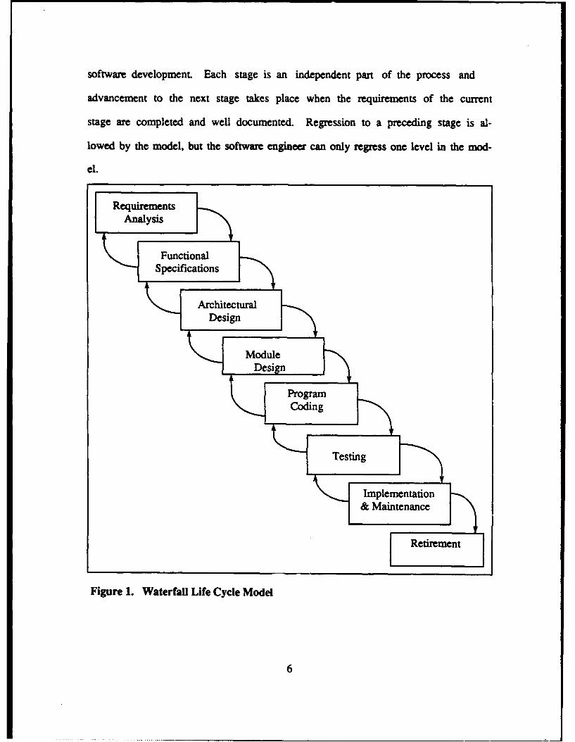
software development. Each stage is an independent part of the process and
advancement to the next stage takes place when the requirements of the current
stage are completed and well documented. Regression to a preceding stage is al-
lowed by the model, but the software engineer can only regress one level in the mod-
el.
RequirementsAnalysis -
Functional . ...
Specifications
FArchitecturalDesign
Design
Coding~etn
& Maintenance
Retirement [
Figure 1. Waterfall Life Cycle Model
6
The Waterfall Model is primarily designed from the software engineer's perspec-
tive. The user is involved with the requirements analysis phase, but then the user
merely waits for the software product in the implementation phase. The lack of user
interaction in the middle to latter phases of the model usually degrades the require-
ments engineering process. Clear and concise definition of user requirements are nec-
essary to allow engineers to develop software to meet the user's needs. In addition
to clear and concise definitions, the requirements definition must remain static
throughout the evolution of the software. This is necessary because of the limitations
of regressing to a former stage, particularly after the architectural design phase is
completed.
Since its introduction, the Waterfall Model has guided the thinking of both DoD
and the civilian software industry. "Most "standard" life cycle models that exist to-
day are based on the Waterfall Model". [Ref. 5: p. 1454] The fact that the Waterfall
Model has survived two decades is testimony to its wide acceptance as a sound life
cycle model. But the rapid advancements in computer technology and the software
engineering community's inability to solve the requirements engineering problems
has driven many researchers to look at alternative life cycle models which will reflect
current technology capabilities and society's growing software requirements.
a. DoD Acceptance Of The Waterfall Model As Its Standard
DoD suffered through much of the 1970's with software failures and misman-
agement of software development projects. The authors revealed in [Ref. 7: p. 1] that
results of a Government Accounting Office (GAO) study of randomly selected federal
government software development/acquisition projects indicated that, of the dollars
spent on projects in the 1970's, 29% resulted in delivery of no software, 47% bought
7
software that was not usable, 19% bought software that required extensive rework
before it could be used (most of which was discarded due to difficulty in maintaining or
modifying it), and only 5% bought software that was either usable as delivered or af-
ter minor modification.
The mounting requirements for software applications in future weapon systems
led DoD to accept the Waterfall Model as the standard for software development and
acquisition in the early 1980's. Numerous regulations were published, notably ME.,-
STD-1679A (Weapon System Software Development, 1983), DoD-STD-2167 and
DoD-STD-2167A (Defense System Software Development, 1985 and 1988 respec-
tively), depicting a life cycle that fits the traditional mold of the Waterfall Model. A
key point to note in DoD's acceptance of the Waterfall Model as standard policy was
the lapse of at least 10 years before it became the standard. The primary reason for
this is that the process of instituting or changing policy in DoD is extremely regulat-
ed. Another reason for the delay is DoD's reluctance to introduce innovative meth-
ods that have not been thoroughly tested and evaluated.
b. Problems With The Waterfall Model By Current Technology Standards
Although the Waterfall Model has been in existence nearly two decades and
has become the standard for DoD software development and acquisition during the
last decade, serious problems exist that are considered unacceptable by today's stan-
dards. The technology is changing so rapidly that often there is incomplete knowl-
edge about software objects, software processes, and available software tools. Often
designers and software engineers do not keep current on advances in their field.
While the technological advances pose problems for current software development
processes, it is not the determinant factor in the community's elevated interest in
8
introducing alternative software development methodologies. The major problem lies
in the software engineering community's frustration and inability to solve the persis-
tent problem of requirements engineering. While there is a resurgence of a need to re-
place the traditional Waterfall Model, the fact is that the methodical foundation and
the scientific approach it brought to the community will forever be the standard from
which new models will be devised.
4. Requirements Engineering (Past/Present)
Requirements engineering is the process of identifying the user's require-
ments, systems requirements, and validating the requirements at the time of software
implementation. Prior to Royce's Waterfall Model, users were often absent during
the entire process. They were usually just a receiver of the software, having to adjust
to its inadequacies. Royce was cognizant of the needs of the user 'and the importance
of input from the user on his or her needs and requirements. Unfortunately, the envi-
ronment that Royce envisioned to implement his software development process was
only present in theory, not in reality.
a. Requirements Analysis
Royce envisioned the user's requirements to be clear, concise, and static
throughout the evolution process. In reality, the requirements often were vague and
constantly changing throughout the evolution of the software development process.
An enormous amount of research was devoted to making the identification and com-
munication of requirements clearer. Users claimed that designers could not translate
the stated requirements into software production. Designers claimed that users did
not know what they wanted and were often changing their requirements. The accusa-
tions and extensive research produced voluminous requirements documents that were
9
confusing to both parties. The common practice was to create the requirements docu-
ment merely to meet the acquisition requirements. Little of the documentation was
actually used in later stages of the development process. The problem still exists.
The problem of users not being able to communicate their requirements is di-
vided into three separate categories: known requirements, unknown requirements,
and technological changes. There are some requirements that are known by the us-
ers, but the art of communicating them to others and transferring those requirements
to paper is a problem that has haunted the software development process from the be-
ginning. There are also unknown requirements that users either don't consider or are
not apparent until after the requirements document is completed. Advances in com-
puter technology may be unknown to users and designers at the requirements phase.
The underlying problem is that requirements engineering is rarely a static pro-
cess. It is dynamic and does not stop after the requirements phase is completed. The
Waterfall Model doesn't support the dynamic nature of requirements engineering. If
requirements change, the development process must regress to the initial phase and
the entire process starts over again. This leads to problems in meeting both produc-
tion costs and completion time constraints. The result is late deliveries of software
and severe cost overruns. This is unacceptable to both designers and users.
b. Requirements Validation
Requirements validation is the process of ensuring that the user's require-
ments are being impleiented as required. In the Waterfall Model, validation is done
at the testing phase and upon delivery of the system. The validation that is done at
the testing phase is conducted by software engineer testing groups, without the us-
er's feedback. So, the validation of requirements is based solely on the requirements
10
document which is published in the initial phases of the model. The user finally vali-
dates the software after program coding, testing, and implementation. Frequent cost
overruns and late deliveries reflect the problems associated with users validating the
software so late in the process. Errors or misrpresented requirements may not be
recognized until the software is completed. Users are rarely amenable to paying for
software that doesn't meet their needs. The software industry cannot continue to
survive with unsatisfied customers and a reputation for software cost gouging and
late deliveries of software products.
5. Boehm Spiral Model
One of the most notable attempts to refine the Waterfall Model was Boehm's
Spiral Model introduced in 1976 [Ref. 7: p. 2]. Boehm explained in [Ref. 4: p. 16] that
the Spiral Model starts with a hypothesis that a particular operational mission could
be improved by a software effort. The spiral process continually tests the hypothe-
sis. At any time if the hypothesis fails the test (for example, if delays cause a soft-
ware product to miss its market windows or if a superior commercial product becomes
available), the spiral is terminated. Otherwise, it terminates with the installation of
new or modified software, and the hypothesis is tested by observing the effect on the
operational versions. This model was moderately accepted by the software engineer-
ing community, but DoD never instituted it as their standard for software develop-
ment and acquisition.
B. OBJECTIVES
The objectives of this thesis are to conduct an extensive survey and evaluation of
proposed alternative software life cycle methodologies and published software life
11
cycle models and to determine the most appropriate software life cycle model to sup-
port future DoD software needs and implementation of rapid prototyping methodolo-
gies.
C. ORGANIZATION
A survey of the rapid prototyping process and the alternative software life cycle
methodologies and models will be presented in Chapter U. An analysis and evalua-
tion of the proposed alternative rapid prototyping methodologies will be presented in
Chapter M. An analysis and evaluation of the proposed alternative rapid prototyping
models will be presented in Chapter IV. Future DoD software engineering require-
ments are discussed and proposed strategic, near-term, short-term, and long-term
goals are presented in Chapter V. The conclusion is presented in Chapter VI.
12
MI RAPID PROTOTYPING
Growing software demands, advances in computer hardware technology, and con-
tinuing frustrations in solving the requirements engineering dilemma have driven the
software engineering community to review existing software development methodolo-
gies and to pursue alternative life cycle models. Research conducted during the past
decade suggests that the most appropriate alternative software development method-
ology is rapid prototyping. The rapid prototyping paradigm is certainly not seen as
the solution to all of the software engineering problems, but offers improvements in
numerous areas. "Rapid prototyping is particularly effective for ensuring that the re-
quirements accurately reflect the real needs of the users, increasing reliability, and re-
ducing costly requirements changes". [Ref. 8: p. 25]
One definition of a prototype is "an original type, form, or instance that serves as a
model on which later stages are based or judged". [Ref. 9] In regard to software de-
velopment, a prototype is an executable model or a pilot version of the intended sys-
tem. "A prototype is usually a partial representation of the intended system, used as
an aid in analysis and design rather than as production software. The construction ac-
tivity leading to such a prototype is called rapid prototyping". [Ref. 10: p. 1]
The use of prototypes in product development is not isolated to the computer sci-
ence field. Civilian industry disciplines, such as the automotive industry, have used
prototypes for years to define design processes and production line operations. The
home building industry is similar by analogy to the software development process in a
13
rapid prototyping environment. Throughout this chapter, comparisons will be made of
the two processes.
The progress of implementation of the rapid prototyping paradigm has not been re-
flective of the word "rapid". One major reason for the delay is the enormous system
support environment and a specification-based protoyping language that must be de-
veloped, tested, and evaluated. DoD has been very active in the new paradigm
through research funding and in sponsoring rapid prototyping conferences and work-
shops.
The dynamic changes in technology and advances in research have resulted in the
publication of alternative strategic representations of the rapid prototyping paradigm.
Currently there are at least five rapid prototyping methodologies. Unfortunately,
these theoretical methodologies have resulted in few models that provide the degree
of specificity or detail to actually implement rapid prototyping in civilian industry and
in DoD.
This chapter will provide an in-depth discussion of the rapid prototyping process
and the impact of its development. The system support requirements and their effect
on the implementation of prototyping will be discussed. The discussion of the require-
ments engineering process will continue from Chapter 1, concentrating on the present
to futue states with respect to the introduction of the rapid prototyping paradigm.
This chapter will conclude with a presentation of the five most notable and researched
rapid prototyping methodologies and three of the published rapid prototyping models.
14
A. RAPID PROTOTYPING PROCESS
The rapid prototyping process is more complex than the conventional defini-
tion suggests. The development of a software prototype, under real-time constraints,
differentiates the software industry from other civilian industry prototyping process-
es. "In the rapid prototyping paradigm, the traditional software cycle used in software
design is replaced by an alternative life cycle which consists of two phases, rapid pro-
totyping and automatic code generation". [Ref. 10: p. 2] Current technology precludes
automatic code generation, but intermediate processes are available to produce par-
tial code generation. In contrast, technology is currently available to implement rapid
prototyping.
The rapid prototyping methodology in a typical feedback loop is presented in Fig-
ure 3 [Ref. 10: p. 3]. Rapid prototyping initially establishes an iterative process be-
tween the user and the designer to concurrently define specifications and require-
ments for the time critical aspects of the envisioned system. The designer then con-
structs a model or prototype of the system through a high-level specification-
based prototyping language. Janson describes the process in [Ref. 2: p. 31 where the
prototype is a partial representation of the system, including only those critical at-
tributes necessary for meeting users requirements, and is used as an aid in analysis
and design rather than as production software. During demonstrations of the proto-
type, the user validates the prototype's actual performance against the expected per-
formance. If the prototype fails to execute properly or to meet any critical timing con-
straints the user identifies required modifications and redefines the critical specifica-
tions and requirements. This process continues until the user determines that the
prototype successfully meets the time critical aspects of the envisioned system.
15
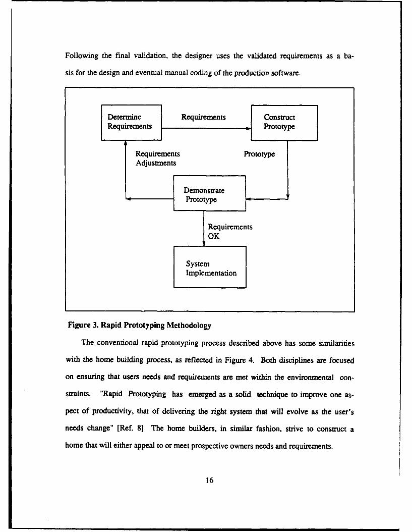
Following the final validation, the designer uses the validated requirements as a ba-
sis for the design and eventual manual coding of the production software.
Determine Requirements ]Construct
Requirements =[Prototype
Requirements PrototypeAdjustments
DemonstratePrototype
RequirementsOK
SystemImplementation
Figure 3. Rapid Prototyping Methodology
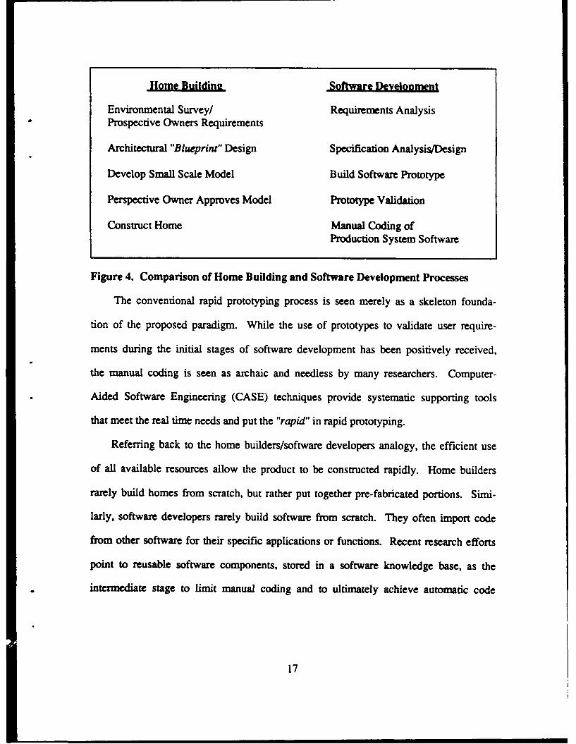
The conventional rapid prototyping process described above has some similarities
with the home building process, as reflected in Figure 4. Both disciplines are focused
on ensuring that users needs and requirements are met within the environmental con-
straints. "Rapid Prototyping has emerged as a solid technique to improve one as-
pect of productivity, that of delivering the right system that will evolve as the user's
needs change" [Ref. 8] The home builders, in similar fashion, strive to construct a
home that will either appeal to or meet prospective owners needs and requirements.
16
Home Buildine Software Development
Environmental Survey/ Requirements AnalysisProspective Owners Requirements
Architectural "Blueprint" Design Specification Analysis/Design
Develop Small Scale Model Build Software Prototype
Perspective Owner Approves Model Prototype Validation
Construct Home Manual Coding ofProduction System Software
Figure 4. Comparison of Home Building and Software Development Processes
The conventional rapid prototyping process is seen merely as a skeleton founda-
tion of the proposed paradigm. While the use of prototypes to validate user require-
ments during the initial stages of software development has been positively received,
the manual coding is seen as archaic and needless by many researchers. Computer-
Aided Software Engineering (CASE) techniques provide systematic supporting tools
that meet the real time needs and put the "rapid" in rapid prototyping.
Referring back to the home builders/software developers analogy, the efficient use
of all available resources allow the product to be constructed rapidly. Home builders
rarely build homes from scratch, but rather put together pre-fabricated portions. Simi-
larly, software developers rarely build software from scratch. They often import code
from other software for their specific applications or functions. Recent research efforts
point to reusable software components, stored in a software knowledge base, as the
intermediate stage to limit manual coding and to ultimately achieve automatic code
17
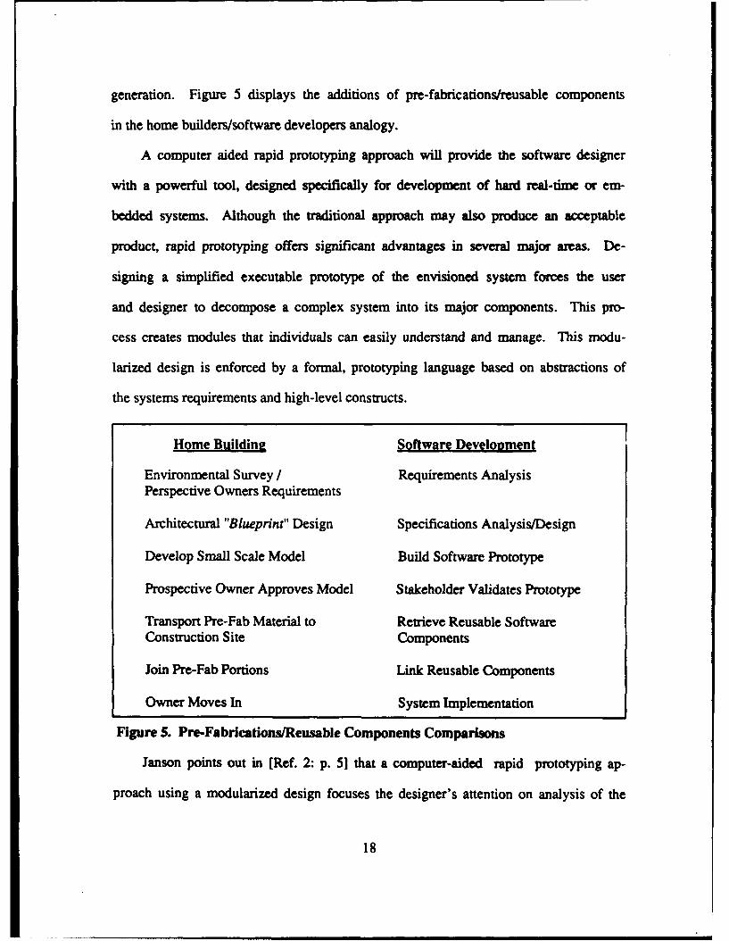
generation. Figure 5 displays the additions of pre-fabrications/reusable components
in the home builders/software developers analogy.
A computer aided rapid prototyping approach will provide the software designer
with a powerful tool, designed specifically for development of hard real-time or em-
bedded systems. Although the traditional approach may also produce an acceptable
product, rapid prototyping offers significant advantages in several major areas. De-
signing a simplified executable prototype of the envisioned system forces the user
and designer to decompose a complex system into its major components. This pro-
cess creates modules that individuals can easily understand and manage. This modu-
larized design is enforced by a formal, prototyping language based on abstractions of
the systems requirements and high-level constructs.
Home Buildinf Software Development
Environmental Survey I Requirements AnalysisPerspective Owners Requirements
Architectural "Blueprint" Design Specifications Analysis/Design
Develop Small Scale Model Build Software Prototype
Prospective Owner Approves Model Stakeholder Validates Prototype
Transport Pre-Fab Material to Retrieve Reusable SoftwareConstruction Site Components
Join Pre-Fab Portions Link Reusable Components
Owner Moves In System Implementation
Figure 5. Pre-Fabrications/Reusable Components Comparisons
Janson points out in [Ref. 2: p. 5] that a computer-aided rapid prototyping ap-
proach using a modularized design focuses the designer's attention on analysis of the
18
requirements and specification of the system. At this stage, the designer should con-
cern himself with the architectural decomposition of a complex system rather than be-
coming engrossed with detailed programming efforts inherent in conventional proto-
typing. This approach allows the user to verify requirements and to identify problem
areas early in the development cycle. This verification process eliminates some of the
expensive redesign efforts and increases the user's confidence in the system..
B. SUPPORT SYSTEM FOR RAPID PROTOTYPING
The speed at which the rapid prototyping paradigm is instituted may very well be
dependent on the development of the necessary support system. "An automated sup-
port system environment is essential for the rapid construction of prototypes". [Ref.
10: p. 29] There has been a considerable amount of research on prototyping tools
which will comprise the support system environment. One perspective of what the
environment should contain is the notion of a prototyping center. A generic list of
tools that the prototyping center should include are presented in Figure 6 [Ref. 11].
Researchers agree that a prototyping system must provide tools that fulfill these
basic requirements. A Text Editor is required to provide word processing functions
during the program code generation, documentation, and modification. The Data Base
Manager is required to manage a reusable software component knowledge base. A
Procedural Language Program Generator is vital to fulfill the automatic code genera-
tion goals of the paradigm and to manage the enormous components
library. Teleprocessing is vital, especially considering the enormous databases
and the increased importance on meeting real-time constraints. Some commercial
software feature automatic Screen Generators. Screens are becoming standardized
19
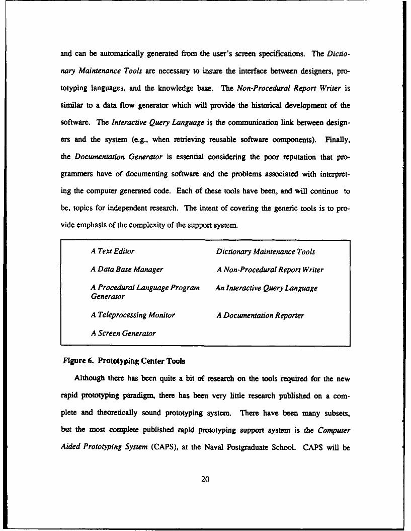
and can be automatically generated from the user's screen specifications. The Dictio-
nary Maintenance Tools are necessary to insure the interface between designers, pro-
totyping languages, and the knowledge base. The Non-Procedural Report Writer is
similar to a data flow generator which will provide the historical development of the
software. The Interactive Query Language is the communication link between design-
ers and the system (e.g., when retrieving reusable software components). Finally,
the Documentation Generator is essential considering the poor reputation that pro-
grammers have of documenting software and the problems associated with interpret-
ing the computer generated code. Each of these tools have been, and will continue to
be, topics for independent research. The intent of covering the generic tools is to pro-
vide emphasis of the complexity of the support system.
A Text Editor Dictionary Maintenance Tools
A Data Base Manager A Non-Procedural Report Writer
A Procedural Language Program An Interactive Query LanguageGenerator
A Teleprocessing Monitor A Documentation Reporter
A Screen Generator
Figure 6. Prototyping Center Tools
Although there has been quite a bit of research on the tools required for the new
rapid prototyping paradigm, there has been very little research published on a com-
plete and theoretically sound prototyping system. There have been many subsets,
but the most complete published rapid prototyping support system is the Computer
Aided Prototyping System (CAPS), at the Naval Postgraduate School. CAPS will be
20
discussed in more detail in section D.1 during the discussion of CAPS Rapid Prototyp-
ing Model.
The development of independent support system tools is innovative and complex.
It is unlikely that the software engineering industry will implement a complete proto-
typing system in the near future. Just as software development is a dynamic process,
the development of the prototyping tools is also dynamic. Advances in computer
hardware technology, particularly in the progress of concurrent and parallel process-
ing, will play a major role in the prototyping tools development process. Improve-
ments in operating systems environments will also be important. There has been
some debate over the requirement for a specific prototyping language. These areas
will be discussed as future considerations for the implementation of the rapid proto-
typing paradigm.
1. Prototyping Language
There is not agreement on whether a new prototyping language is necessary to
implement the new paradigm. The researchers that reject the need for a prototyping
language are primarily in the Management Information Systems (MIS) environment
and have small scale applications. One such application is a public accessing kiosk
used by Aetna Life and Casualty, which is executed on a MacIntosh Computer Sys-
tem. The authors of [Ref. 12] discard the additional requirements for a prototyping
language and state that mere understanding of the system will enable the production
of prototypes. They contend that existing relational data base languages are ade-
quate to develop the prototypes for their applications. The specifications are
validated by using a storybook technique of displaying the prototypes on a wall in hi-
erarchical fashion. While this approach may be relevant in some cases, the need for a
21
prototype on such small scale applications is suspect. The rapid prototyping para-
digm is intended theoretically for large real-time systems, which fit the majority of
DoD's current and future software needs.
'The languages used in the CASE paradigms differ from the languages used in
traditional software development because of the need for supporting a higher level of
automation at the early stages". [Ref. 13: p. 1] The ordy existing programming lan-
guage that has the potential to support rapid prototyping is DoD's programming lan-
guage Ada. Though Ada lacks adequate semantic qualities and specification-based
requirements some researchers, such as Dr. Winston Royce, feel that modifications
to the existing language would provide the language requirements necessary to sup-
port the rapid prototyping paradigm. If Ada is modified, two serious concerns are
raised. The first and most important is DoD's willingness to support the proposed
modifications and handle the additional problems associated with maintaining and ret-
rofitting existing DoD software. The second is whether, after the modifications are
made, there will be any resemblance to the present Ada language. This concern sup-
ports the need for a new prototyping language. However this is resolved, the lan-
guage that will support the new paradigm must be formal and must contain both speci-
fication and design based features.
Dr. Berzins explains in [Ref. 13: pp. 2-3] that a formal language is a notation
with a clearly defined syntax and semantics. Formal languages are critical compo-
nents of a CASE environment because they are needed to achieve significant levels of
computer-aided design with currently feasible technologies. Automated tools are
capable of detecting structure in a notation only if the structure has been formally de-
fined, and of responding to aspects of its meaning only if the me.,ing of the aspect
22
has been formally defined. The tools applicable to informal notations usually treat
them as uninterrupted text strings, which limits the tools to bookkeeping functions,
such as version control. Notations with a formally defined syntax, but informal se-
mantics can support tools sensitive to the structure of the syntax, such as pretty
printers and syntax-directed editors. If both the syntax and semantics of a special
purpose language have been fixed and are clearly defined, it becomes possible to cre-
ate automated tools for analysis, transformations, or execution of the aspects of the
software system captured by the language and its conceptual model.
Dr. Berzins points out in [Ref. 13: p. 5] that formal specification languages are
the basis of CASE. An adequate specification language will have the maximum ex-
pressive capability and formalism for supporting mechanical processing of software.
To fully support the CASE requirements, integration of the specification language, de-
sign language, and prototyping language are necessary. The main purpose of a speci-
fication language is to define the interface or to record a specification. A specification
is a black-box description of the behavior of a software system or one of its compo-
nents. A black-box description explains the behavior of a software component in
terms of the data that crosses the boundary of the box, without mentioning the mecha-
nism inside the box. The design language defines the structure of the system.
A design is a glass-box description of a software system or component. A glass-box
description gives the decomposition of a component into lower-level components and
defines their interconnections in terms of both data and control. A specification says
what is to be done and a design says how to do it.
Prototyping languages are designed to produce executable prototype versions
of the production system, to be able to demonstrate the real-time constraints, and to
23
record and test interfaces and interconnections. The prototyping language defines the
executable model of a system by using both black-box and glass-box descriptions. A
prototyping language has no obligation to define detailed algorithms for all compo-
nents of the system as long as it is descriptive and produces an executable proto-
type. It supports simple and abstract system descriptions, locality of information, re-
use, and adaptability at the expense of execution efficiency. Dr. Luqi presented a
survey in [Ref. 14] of two specification-based languages, MSG (MeSsaGe) and
SPEC (SPECification Language); and a specification/design-based language, PSDL
(Prototyping System Description Language).
MSG is a specification language which is useful for functional specifications.
MSG is based on the actor model of computation, where actors are independent ac-
tive elements that interact solely by sending each other messages. The MSG specifi-
cation is defined through an algorithm which uses the actor modules and primitive con-
structs. Experience has shown that MSG is a relatively simple language that is
learnable by both experienced and novice programmers. MSG is a formal tool allow-
ing system designers to abstract specifications and to communicate design decisions
to each other without getting bogged down in implementation details.
SPEC is a language for writing black-box specifications defined in the functional
specification and architectural design of the software system. It is designed to simpli-
fy the design and description of large systems without introducing details of the exter-
nal structure. It assists the analyst in constructing a simple conceptual model for the
intended system and to establish and maintain its conceptual integrity. Based on the
evert model of computation, SPEC uses predicate logic to define the basic behavior of
the modules, defined concepts, and an inheritance mechanism that is needed mostly
24
for specifying large systems. SPEC has precise semantics and a simple underlying
model and has been found to sufficiently support mechanical processing.
MSG was the foundational specification language from which SPEC evolved.
The major improvements with SPEC are the ability to integrate time into the underly-
ing model, the development of an inheritance mechanism, and the improved locality of
information.
PSDL is a combination of specification and design based languages designed to
support rapid prototyping. It supports the specification of the requirements for the
system and functional descriptions for the component modules. It is designed to han-
dle hard real-time constraints and is based on a simple computation model that close-
ly resembles the designer's view of real-time systems.
Currently compilers and hardware technology do not allow distinctions between
different types of languages discussed above. As programming languages become
more advanced and hardware technology improves, the probability of complete inter-
action between hardware and software systems will increase. This advance-
ment will produce a more efficient implementation of the rapid prototyping paradigm.
A prototyping language appears necessary. DoD's interest and investment in Ada
point to the need to build the prototyping language to interact with Ada or be built up-
on it.The issue of whether one prototyping language will be sufficient to meet all the
rapid prototyping needs of the future is currently not resolved. Historically we have
found that one language does not meet all software development needs.
The effectiveness of the prototyping language will be its ability to interact with the
tools of the prototyping environment. Since there currently exists only one published
25
prototyping environment, CAPS, it is difficult to determine if the prototyping language
of CAPS, PSDL, is capable of handling all applications of future software develop-
ment. PSDL appears to be sufficient to handle the underlying requirements of CAPS,
and therefore appears to be a good candidate for an acceptable language from which
the new rapid prototyping paradigm can be implemented. Since PSDL is currently be-
ing written primarily in Ada, it is acceptable to DoD. This is based purely on theory
and further evaluation will have to be conducted once the tools and CAPS is fully de-
veloped to determine if it truly meets the needs of DoD.
2. Operating System Considerations
There has been a lot of research on how to conduct rapid prototyping. The prim-
itive prototyping tools currently being introduced by industry have raised new con-
cerns in the computer science community. One issue that is rarely discussed in the
research of rapid prototyping is how operating systems will support the new CASE
tools, reusable software components knowledge bases, and portability. There are
two main reasons why this issue is not included in current research papers being pub-
lished. The most significant reason is that UNIX operating systems and Sun Work-
stations are currently used for the design and construction of the prototyping tools in
academic environments. The other reason is that until hardware architecture is capa-
ble of parallel processing, there doesn't appear to be any significant change to the cur-
rent design of operating systems. Therefore, the current environment is believed to
be stable enough to get prototyping into the field and more importantly on the market.
It is clear by the term "rapid" that the intent of the methodology is to "rapidly"
construct an executable prototype from which requirements validation can be
achieved. Theoretically, this should greatly reduce the current problems associated
26
with requirements engineering. But what are the costs associated with this method-
ology? This question can be answered by looking at the system environment that af-
fects real-time constraints. The prototyping tools will affect real-time systems. An-
other element of the methodology is to reduce the amount of human coding by imple-
menting automatic code generation through reusable software components.
Another area to consider is how the operating system will manage the resources
necessary to support rapid prototyping. With regard to real-time constraints, one
could conclude that multiple processors are required. Single processor systems do
not optimize the development process and prevent the process from meeting its true
real-time constraints. Concurrent and parallel processing thus become desirable.
Rapid prototyping on these powerful operating systems is highly desirable. However,
many research problems have to be addressed before it becomes practical. "As hard-
ware architecture advances to support parallel processing, it is believed that modifica-
tions can be made to existing prototyping environments to allow processes to run
in parallel". [Ref. 11: p. 81 The major impact that parallel processing would have on
rapid prototyping is the improvement in prototype production time, moving closer to
meeting true real-time constraints.
Bell Labs' UNIX operating system has gained popularity industry wide, as well
as in DoD, as the best operating system to support rapid protocyping. One important
aspect of UNIX is that it supports concurrency and encourages a tool oriented building
block approach to program design. Its resource management, in terms of memory
management and input/output mechanisms, is more than adequate for the require-
ments of prototyping. Paging is an efficient means of managing memory in support of
not only the prototyping tools, but also in anticipation of linking reusable software
27
components from knowledge bases. Currently, UNIX supports fixed-sized paging
and uses a first-fit placement strategy. Even though fixed-sized paging and first-fit
strategies are subject to memory waste, the benefits outweigh the added costs of in-
creased overhead associated with managing variable-sized paging and best-fit place-
ment strategies. In addition to the stable environment that UNIX's fixed-sized pag-
ing offers, the sufficient number of system calls to increase memory for large process-
es offsets the disadvantages of having fixed-sized pages.
The UNIX-based Sun Workstation is another reason why UNIX is the indus-
try's apparent choice for rapid prototyping. The Sun Workstation is an integrated
system which has access to all the library functions and applications pointed out as
advantageous in the UNIX operating system. The Sun Workstation provides each
process with its own private protected virtual address space. It has internal proces-
sors that operate within the UNIX operating system. It offers multi-user and
multi-tasking which facilitates designer needs in constructing prototypes.
One popular aspect of the Sun Workstation is the attractive user interface ca-
pabilities. The multiple windows, icons, and other sundry interface facets likens the
environment to the MacIntosh environment without the PC limitations. This is impor-
tant because users are generally not computer scientists and therefore are considered
novices who have shown great acceptance to the user interface applications.
So, current operating systems technology appears to be suitable for supporting
many of the prototyping tools being built. CAPS is currently being built using Sun
Workstations. Although these CAPS tools are being built on a smaller scale than
theoretically proposed, it appears that the UNIX operating system is capable of sup-
porting them individually. The issue is not whether the independent prototyping tools
28
can be built on current existing systems, but how the operating system will handle al-
locating the resources required once the tools are integrated.
To highlight the problem, consider how Ada constructs are used to link packages
to build programs. The programmer declares what packages are to be retrieved and
linked to other declared packages. The Ada compilation process is criticized by many
as too slow in comparison to other programming languages. Now consider the added
requirements to constructing the program by using CAPS. However, since the tools
perform tasks that must be done manually using other languages, a fair comparison
must include manual processes.
The designer declares the specification of the component to be retrieved from the
knowledge base. The specifications are then put through the syntax-directed editor
to ensure that specifications are syntactically correct. At this time there are portions
of PSDL, the reusable software components, and the syntax-directed editor that are
residing in real memory. As the components are retrieved and placed in real memory,
the graphics editor must also be in real memory allowing the data flow diagrams to be
developed or modified. So now there are at least four major prototyping tools in real
memory, all executing concurrently. An additional strain is the input/output mecha-
nisms that are being tasked by each of these processes and the use of costly resourc-
es. It is clear that the operating system has a much greater task of managing resour,:-
es with CASE tools.
UNIX has been supporting versions of Ada with relative success, but it is no
secret that end users are less than satisfied with the excessive time required for pro-
gram compilation. This is an important aspect as Ada constructs offer many of the ba-
sic fundamental operations that rapid prototyping requires. The generic template,
29
instantiation in Ada can be used for retrieval of and linking reusable software compo-
nents from a knowledge base.
The database management strategies and the tools designed to retrieve and
link reusable software components play an important part in meeting real-time con-
straints, but how the system manages memory and input/output operations also af-
fects the speed by which the prototype can be built. There is speculation that the cur-
rent technology will be able to support reusable software components, but the reality
is that the software methodology has not yet been implemented. Although the soft-
ware engineering community might be initially satisfied, for the sake of getting an ini-
tial version, if the implementation suffers some of the same problems that Ada lan-
guage suffers, the industry will fall short of meeting its rapid prototyping goals.
Although there is no analytical evidence to support whether current operating
systems can support the implementation of reusable components, there are concerns
about whether creating excessive strains on the system may result in slower sys-
tems and possibly force a reevaluation of current technology. The primary reason for
the absence of discussion concerning operating systems in researching reusable soft-
ware components is due in part to the relative success of Ada and UNIX, as well as
to the intense research into database management and design to support the imple-
mentation. The paradigm calls for the tools to operate with the concurrency associat-
ed with the input/output operations of retrieving and linking reusable software
components. Current small scale productions, which are being used as prototype ver-
sions of the production prototyping system, are functioning efficiently but independent
of any other tools or knowledge bases. As the tools are integrated, the system's ef-
ficiency and speed of production likely will be an important issue. The question that
30
needs answering is how much decreased efficiency is acceptable not only today, but
in the future.
Since the industry is using operating systems in addition to UNIX, the issue of
tools being designed and built on different operating systems strikes at the core of
real-time constraints. The performance of a tool on a non-UNIX based system may
be very different, faster or slower, than the performance of a tool on a UNIX based
systems. This is assuming that the prototyping tools can run on other operating sys-
tems. There is a lack of research on this issue. This is mainly due to the economic
push to get prototyping into the market with current technology. Another important
reason is that tools have not been developed to the point that they are ready to be in-
tegrated with other tools, let alone with other operating systems.
The UNIX operating system has continually been upgraded and newer versions
unveil more efficient means of managing resources and supporting hardware architec-
tures. It is predicted, by many leading researchers, that production level prototypes
are at least a decade away. Current tools take one to two and a half years to build.
How many versions of the UNIX operating system will evolve during either of these
development periods is unknown. It is certainly an issue worthy of further research to
ensure that we don't find ourselves "recreating the wheel" ten years down the road.
The current technology of operating systems, especially with UNIX based sys-
tems, is theoretically adequate to support the rapid prototyping paradigm. It is
definitely adequate to support the near-term goal which is to build the independent
prototyping tools to support the new environment. It is unclear whether the short-
term goal of integrating the tools on a small scale prototyping environment can be
supported with the current system. In all probability, the environment will be
31
adequate, even if industry must modify the goals of the paradigm. This modification is
driven by the economic incentives for industry to produce a working prototyping sys-
tem environment. The long-term goal of having executable rapid prototyping environ-
ments supporting reusable software components, automatic specifications, design,
and coding is many years away.
"As processor architectures have nearly reached their limit in so far as cycle
times are limited by the speed of light, the next area of improvement in Computer Sci-
ence will come from parallel processing". [Ref. 15: p. 50] It may be the case that par-
allel architecture arrives first. As soon as a parallel architecture is available, operat-
ing systems will have to undergo revision. Since this is a very real possibility, the
portability and maintenance of our existing or developing prototyping system will
have to be modified, at least, and very possible reworked. Even though industry wel-
comes the dynamic situation, DoD should take a firm stance now on the commitment
to rapid prototyping.
3. Software Maintenance
"Software maintenance is a very broad area that includes error corrections, en-
hancements of capabilities, deletion of obsolete capabilities, optimization, and adapta-
tion of changes in operating environments". [Ref. 16: p. 1128] With software mainte-
nance accounting for well over half of the current software costs, any new software
development methodology must account for an efficient software maintenance method-
ology. The current methodology of software maintenance is presented in Figure 7.
The authors explain in [Ref. 16: p. 1128] that the first phase of the maintenance
process consists of program analysis. The second phase consists of generating a par-
ticular modification proposal to accomplish the implementation of the maintenance
32
objectives. The third phase consists of accounting for both logical and performance
ripple effects as a consequence of program modifications. The fourth phase coisists
of testing the modified program to ensure that the modified program has at least the
same reliability as before.
The modifications of phase 3 are generally considered the most expensive of the
software maintenance costs. The modifications are responses to requirements
changes. These enhancements may be planned or unplanned. "It is the unplanned en-
hancements that are the most expensive because they tend to affect larger parts of
the system than with planned changes". [Ref. 17: pp. 2-3]
Dr. Luqi claims in [Ref. 17: pp. 3-4] that the new rapid prototyping paradigm can
help to reduce the growing software maintenance costs. The improvements in the re-
quirements engineering process, particularly in the requirements analysis phase,
should reduce the costly unplanned enhancements. Prototyping can help reduce main-
tenance costs by making the original requirements conform closely to the real needs
of the users. Systerps that correctly implement an accurate set of requirements have
lower maintenance costs because there are fewer surprises when the system is put
into actual use. Rapid prototyping also helps reduce corrective maintenance by ensur-
ing the system design is capable of meeting the systems performance before substan-
tial effort is spent on system implementation.
The CASE prototyping tools that are vital elements of the new rapid prototyping
environments should help to decrease the costs. The tools can increase the leverage
of the prototyping strategy by reducing the effort that must be spent by the designer
in producing and adapting a prototype to the perceived user needs. The automation of
the prototyping process enhances the interaction between the users and designers,
33
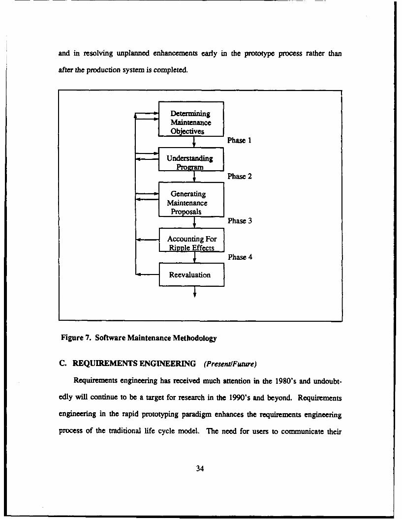
and in resolving unplanned enhancements early in the prototype process rather than
after the production system is completed.
Maintenance
Phase 2SUnderstanding Irrm
I Phase 2
~GeneratingMaintenanceSPropo s
IPhase 3
H Accounting For
Ifet Phase 4
Reevaluation
Figure 7. Software Maintenance Methodology
C. REQUIREMENTS ENGINEERING (Present/Future)
Requirements engineering has received much attention in the 1980's and undoubt-
edly will continue to be a target for research in the 1990's and beyond. Requirements
engineering in the rapid prototyping paradigm enhances the requirements engineering
process of the traditional life cycle model. The need for users to communicate their
34
requirements to designers and for requirements documentation still exists. The major
improvements will be how the requirements are implemented into the software, how
the requirements are validated and tested, and how the rapid prototyping model han-
dles changing requirements and enhancements.
1. Requirements Analysis
As noted in 1.4.A, requirements analysis in the traditional model is mired in
problems that have been very difficult to solve. "Prototyping is most applicable as a
software development approach when understanding the problem is a problem - that
is in domains where problems are ill structured and poorly understood". [Ref. 18: pp.
211-212] It is not likely that an optimal requirements analysis process will ever be
achieved, primarily due to the dynamic state of software demands and computer tech-
nology. But significant improvements can be achieved in the near future which will
make software production more efficient and amenable to user's needs.
New methods of conducting the requirements analysis process are being evalu-
ated and the communication problems between users and designers have decreased.
The new methods demand more group interaction between users and designers. The
use of group discussion leaders, usually consisting of junior level/middle-level
management from the software industry, has proven successful in defining the us-
er's requirements and ensuring that the designers understand the needs of the us-
ers. Software Storming is one of the new methods that is presently being implement-
ed at the Mitre Corporation [Ref. 19].
Software Storming is based on the brainstorming problem-solving technique.
The process incorporates experts into the initial design and implementation phases of
a system, thus combining knowledge engineering with the latest advances in
35
software development technology and workstation hardware. "Recent evaluations of
the software storming process have produced a more functional prototype in four
months than the conventional methods do in two years". [Ref. 19: p. 39] The soft-
ware storming process is presented in Figure 8 [Ref. 19: p. 40]. The difference be-
tween the software storming process and the conventional prototyping process is the
speed at which the storm process can be completed. The storming process results in
an initial prototype and the follow-on phase takes the initial prototype and makes it
executable.
The Mitre Corporation used the storming process on a U.S. Army sponsored
communication system software project [Ref. 19]. The software product was deliv-
ered in a greatly reduced amount of time and at a fraction of the cost of developing
comparable software under the conventional means. The results are encouraging, but
also subject to speculation. This experiment reveals that if the development time and
cost can be reduced without the aid of CASE prototyping tools, then the proposed rap-
id prototyping paradigm should reduce development time even more. The scope of the
project is subject to speculation. The project involved networking in a mobile sub-
scriber equipment system. It was a relatively large system, but was supported by
abundant technical specifications and was similar in context to the basic networking
theory of Computer Science. For this reason, the ability to meet the determined time
constraints of the storming phase is subject to speculation. The other issue is wheth-
er the industry and users can devote the dedicated time required by the storming pro-
cess and how this devotion will affect software production costs in the future.
36
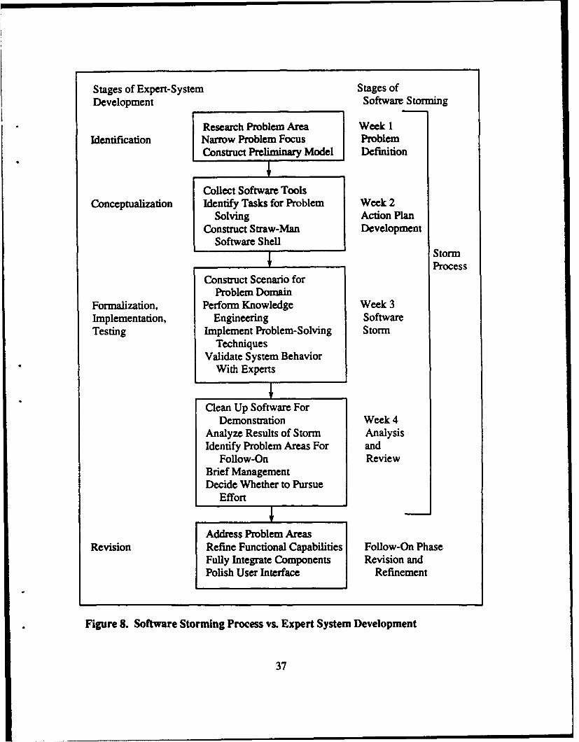
Stages of Expert-System Stages ofDevelopment Software Storming
Research Problem Area Week 1
Identification Narrow Problem Focus ProblemConstruct Preliminary Model DefinitionICollect Software Tools
Conceptualization Identify Tasks for Problem Week 2Solving Action Plan
Construct Straw-Man DevelopmentSoftware Shell_____________Storm
Process
Construct Scenario forProblem Domain
Formalization, Perform Knowledge Week 3Implementation, Engineering SoftwareTesting Implement Problem-Solving Storm
TechniquesValidate System Behavior
With Experts
Clean Up Software ForDemonstration Week 4
Analyze Results of Storm AnalysisIdentify Problem Areas For and
Follow-On ReviewBrief ManagementDecide Whether to Pursue
Effort
Address Problem AreasRevision Refine Functional Capabilities Follow-On Phase
Fully Integrate Components Revision andPolish User Interface Refinement
Figure 8. Software Storming Process vs. Expert System Development
37
It is apparent that through the successful experimentation of new methods, such
as the storming process, requirements analysis stages in the future will be oriented
on group dynamics and some form of brainstorming techniques. This is definitely a
positive move and can be supported by the sociological experiments of the 1970's and
early 1980's with group dynamics. The ability to define requirements in the require-
ments analysis stage will be greatly enhanced by the process of group (users and de-
signers) discussion forums and with executable prototypes.
2. Requirements Validation
The greatest impact that the rapid prototyping paradigm will have on the re-
quirements engineering process is improvements in requirements validation. As dis-
cussed in 1,4.B, the conventional life cycle model allowed the initial requirements vali-
dation to proceed without the designers in the testing phase, and with the participa-
tion of the users only after the software product is complete and delivered. Results of
surveys and experience from the 1980's have shown that requirements validation so
late in the software development process is costly. Rapid prototyping moves the ma-
jority of the requirements validation process up into the requirements analysis phase.
This has three major objectives. One is that the users are given the responsibility of
validating the executable prototype to ensure that their needs are reflected in the ini-
tial versions of the software. The second objective is to reduce production costs.
By validating the prototypes so early in the process, the costs associated with mak-
ing modifications or enhancements are reduced because the prototype is on a smaller
scale than the larger production system. The ripple effects are reduced and therefore
maintenance costs are greatly reduced. The last major objective is that before the
software goes into the production phase, requirements validation is for the most part
38
complete, and the validation increases the probability of user satisfaction upon deliv-
ery. Although requirements validation continues throughout the software develop-
ment process, with -validation of the software upon delivery, discrepancies in stated
and executed requirements should be minimal. This enhancement to the requirements
engineering process will improve the traditional process, but will not provide the opti-
mal solution. The problem of dynamic requirements changes, particularly during the
system implementation phase, will have to be addressed. The task of regressing to
the requirements phase in the rapid prototyping paradigm is much easier and less
costly than to do the same in the traditional model. Although the mechanics of re-
gressing back to early stages is improved, the problem of meeting delivery deadlines
becomes a concern. While the optimal solution may not be currently avail-
able in research publications, the tremendous improvements made in the rapid pro-
totyping paradigm certainly rejuvenates the computer community's hope for achieving
that goal.
D. ALTERNATIVI SOFTWARE ENGINEERING LIFE CYCLE
METHODOLOGIES AND MODELS
The current problems associated with the traditional Waterfall Life Cycle Model
have resulted in the need for an alternative software engineering life cycle model.
The problems of the traditional model have been presented in Chapter 1. The new
rapid prototyping paradigm has been represented in generic terms in the previous sec-
tions of this chapter. There are, however, differing perceptions on how to implement
the new paradigm. There are five different methodologies for implementing the new
paradigm. These methodologies cover the spectrum of the ability to implement the
39
paradigm in the near-term, short-term, and long-term with regard to computer tech-
nologies.
Each of these methodologies are supported by valid scientific and problem-solving
means. Unfortunately, the extensive research and publication of these methodologies
has resulted in only three published rapid prototyping life cycle models. There may
be more models being developed, but they are either only locally published in academ-
ic institutions or have not been completed. Undoubtedly we will see more models, es-
pecially as the current published models near implementation and undergo evaluation.
1. Alternative Methodologies
"A methodology is the system of principles, practices, and procedures applied to
any specific branch of knowledge". [Ref. 8] With respect to software development,
these methodologies are the global or strategic principles of how the proposed para-
digms should be modeled for implementation. The architects of these alternative
methodologies do not refer to them as life cycle models. They evolve into life cycle
models, as did Dr. Royce's Waterfall Model. Any one of these five methodologies
raay become the software life cycle model of the 1990's or in the next century. The
most probable is that an integration of two or more will eventually be the standard for
software development of the future.
a. Rapid Throwaway Prototyping Methodology
The authors noted in [Ref. 7: p. 5] that the rapid throwaway methodology ad-
dresses the issue of how to ensure that the software product being developed will
meet the user's needs. An informal representation of the rapid throwaway prototyp-
ing methodology is presented in Figure 9. The rapid throwaway prototyping approach
is to construct a "quick and dirty" partial implementation of the system prior to
40
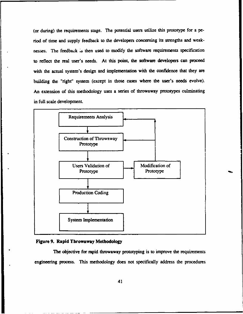
(or during) the requirements stage. The potential users utilize this prototype for a pe-
riod of time and supply feedback to the developers concerning its strengths and weak-
nesses. The feedback s then used to modify the software requirements specification
to reflect the real user's needs. At this point, the software developers can proceed
with the actual system's design and implementation with the confidence that they are
building the "right" system (except in those cases where the user's needs evolve).
An extension of this methodology uses a series of throwaway prototypes culminating
in full scale development.
Requirements Analysis [..
Construction of Throwaway 1Prototype 1
Users Validation of Modification ofPrototype Prototype
Production Coding
System Implementation
Figure 9. Rapid Throwaway Methodology
The objective for rapid throwaway prototyping is to improve the requirements
engineering process. This methodology does not specifically address the procedures
41
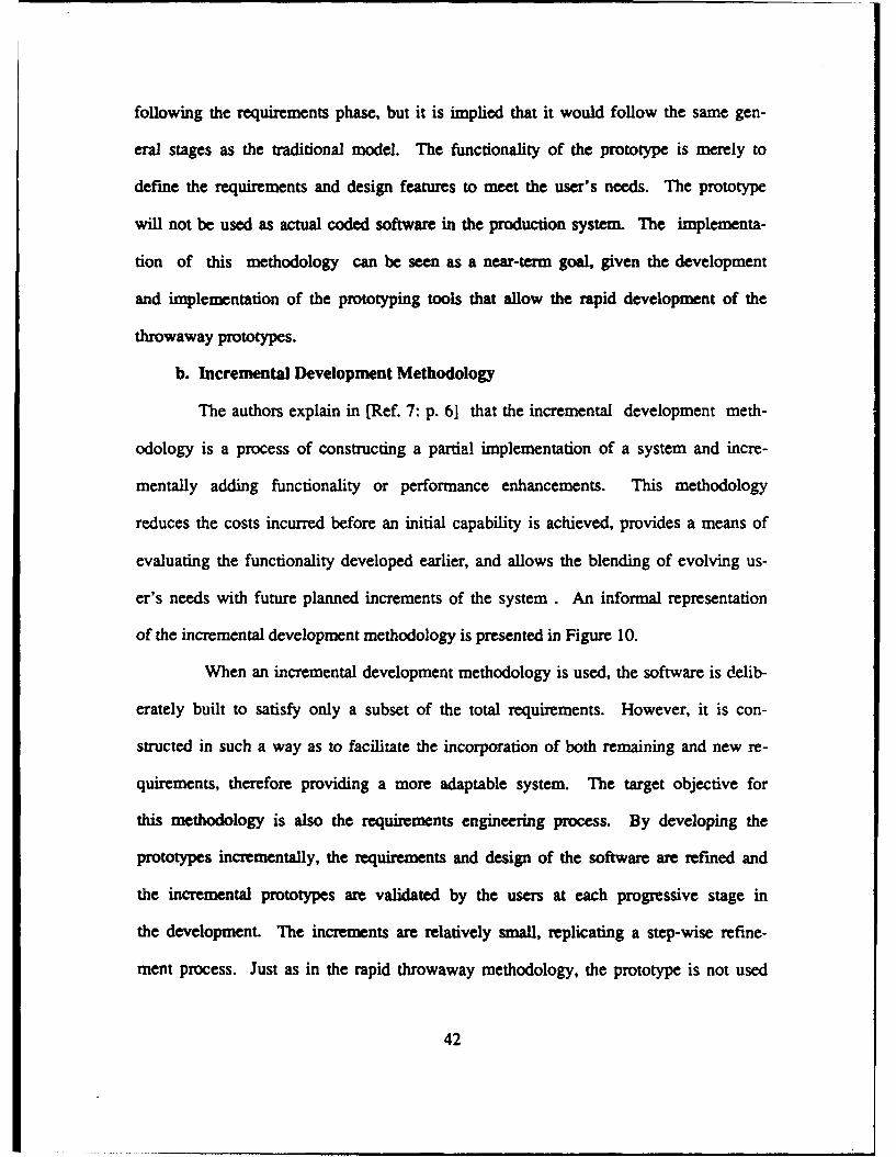
following the requirements phase, but it is implied that it would follow the same gen-
eral stages as the traditional model. The functionality of the prototype is merely to
define the requirements and design features to meet the user's needs. The prototype
will not be used as actual coded software in the production system. The implementa-
tion of this methodology can be seen as a near-term goal given the development
and implementation of the prototyping tools that allow the rapid development of the
throwaway prototypes.
b. Incremental Development Methodology
The authors explain in [Ref. 7: p. 6] that the incremental development meth-
odology is a process of constructing a partial implementation of a system and incre-
mentally adding functionality or performance enhancements. This methodology
reduces the costs incurred before an initial capability is achieved, provides a means of
evaluating the functionality developed earlier, and allows the blending of evolving us-
er's needs with future planned increments of the system . An informal representation
of the incremental development methodology is presented in Figure 10.
When an incremental development methodology is used, the software is delib-
erately built to satisfy only a subset of the total requirements. However, it is con-
structed in such a way as to facilitate the incorporation of both remaining and new re-
quirements, therefore providing a more adaptable system. The target objective for
this methodology is also the requirements engineering process. By developing the
prototypes incrementally, the requirements and design of the software are refined and
the incremental prototypes are validated by the users at each progressive stage in
the development. The increments are relatively small, replicating a step-wise refine-
ment process. Just as in the rapid throwaway methodology, the prototype is not used
42
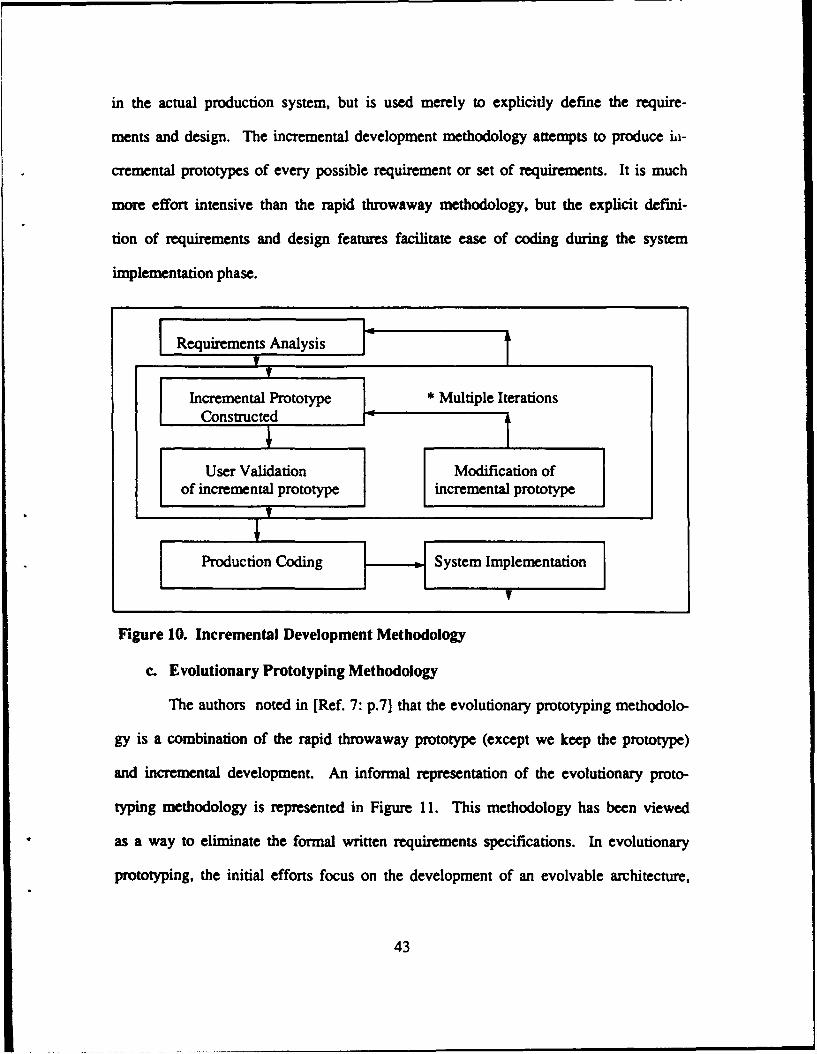
in the actual production system, but is used merely to explicitly define the require-
ments and design. The incremental development methodology attempts to produce ii-
cremental prototypes of every possible requirement or set of requirements. It is much
more effort intensive than the rapid throwaway methodology, but the explicit defini-
tion of requirements and design features facilitate ease of coding during the system
implementation phase.
SRequirements Analysis i
Incremental Prototype * Multiple IterationsConstructed
User Validation Modification ofof incremental prototype incremental prototype
Production Coding ystem Implementation
Figure 10. Incremental Development Methodology
c. Evolutionary Prototyping Methodology
The authors noted in [Ref. 7: p.7] that the evolutionary prototyping methodolo-
gy is a combination of the rapid throwaway prototype (except we keep the prototype)
and incremental development. An informal representation of the evolutionary proto-
typing methodology is represented in Figure 11. This methodology has been viewed
as a way to eliminate the formal written requirements specifications. In evolutionary
prototyping, the initial efforts focus on the development of an evolvable architecture,
43
as wel as a part of the system functionality which meets a known set of require-
ments. The executable prototypes are then used operationally by the users in order
to understand the remaining requirements better. Evolutionary prototyping differs
from incremental development in that we do not initially undersand all the require-
ments and need to experiment in an operational environment to learn them. With in-
cremental development we understand the requirements but implement them in sub-
sets of increasing capability. Also, evolutionary prototypes tend to focus on the
best understood points of the system and build upon strengths, whereas throwaway
prototypes focus on those aspects that are least understood. The development of ev-
olutionary prototypes (which evolve into operational systems), is not necessarily
"rapid", since reliability, adaptability, modularity, and performance are required in an
operational system, and are major time consuming development features.
The evolutionary prototyping methodology is more efficient than the two former
methodologies since it uses the prototypes as part of the production system and
re-coding does not have to be done. This reduces the possibility of program coding
errors or design differences from the actual prototype the user validated. The method-
ology should result in a production system that more closely meets the user's require-
ments and needs and should be less costly in terms of production. The process of de-
veloping an evolutionary prototype is very complex and tool dependent. The imple-
mentation of this methodology is more of a short-term goal of the computer industry,
with the actual development of the prototyping system symbolizing the fuel that pro-
pels its implementation.
44
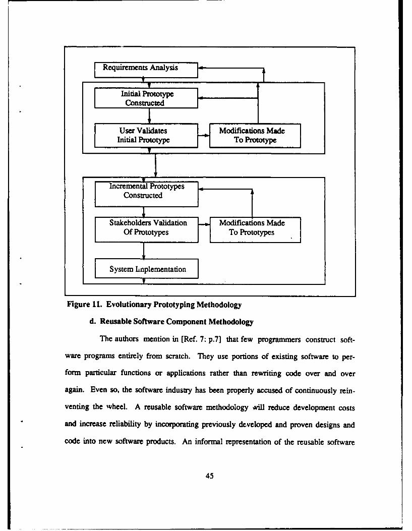
Requirements Analysis
Initial PrototypeConstructed
User Validates Modifications MadeInitial Prototype To Protoyp
F System hinplementation
Figure 11. Evolutionary Prototyping Methodology
d. Reusable Software Component Methodology
The authors mention in [Ref. 7: p.7] that few programmers construct soft-
ware programs entirely from scratch. They use portions of existing software to per-
form particular functions or applications rather than rewriting code over and over
again. Even so, the software industry has been properly accused of continuously rein-
venting the wheel. A reusable software methodology viU reduce development costs
and increase reliability by incorporating previously developed and proven designs and
code into new software products. An informal representation of the reusable software
45
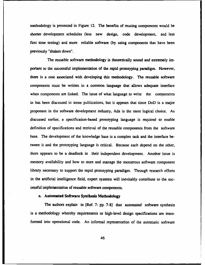
methodology is presented in Figure 12. The benefits of reusing components would be
shorter development schedules (less new design, code development, and less
first time testing) and more reliable software (by using components that have been
previously "shaken down".
The reusable software methodology is theoretically sound and extremely im-
portant to the successful implementation of the rapid prototyping paradigm. However,
there is a cost associated with developing this methodology. The reusable software
components must be written in a common language that allows adequate interface
when components are linked. The issue of what language to write the components
in has been discussed in some publications, but it appears that since DoD is a major
proponent in the software development industry, Ada is the most logical choice. As
discussed earlier, a specification-based prototyping language is required to enable
definition of specifications and retrieval of the reusable components from the software
base. The development of the knowledge base is a complex task and the interface be-
tween it and the prototyping language is critical. Because each depend on the other,
there appears to be a deadlock in their independent development. Another issue is
memory availability and how to store and manage the monstrous software component
library necessary to support the rapid prototyping paradigm. Through research efforts
in the artificial intelligence field, expert systems will inevitably contribute to the suc-
cessful implementation of reusable software components.
e. Automated Software Synthesis Methodology
The authors explain in [Ref. 7: pp. 7-8] that automated software synthesis
is a methodology whereby requirements or high-level design specifications are trans-
formed into operational code. An informal representation of the automatic software
46
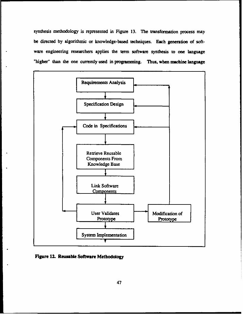
synthesis methodology is represented in Figure 13. The uansformation process may
be directed by algorithmic or knowledge-based techniques. Each generation of soft-
ware engineering researchers applies the term software synthesis to one language
"higher" than the one currently used in programming. Thus, when machine language
[ Requirements Analysis 1:
Especifcation DesignI
~Code in Specifications ]
Retrieve ReusableComponents FromKnowledge Base
Link Software
Components
User Validates Modification ofPrototype Prototype
[ System Implementato
Figure 12. Reusable Software Methodology
47

was used, software synthesis referred to the automatic translating of assembly lan-
guage into machine code (now called assembly). Later it referred to the translation of
a higher-level language into machine code (now called compilation). Now it refers to
the translation of very high-level languages (VHLL's) into machine code. As a de-
signer, potentially even the user, recognizes the uqrements; they are specified in
some type of VHLL and the system is automatically synthesized. The focus of activi-
ty is in the simple specification of requirements and the installation and operation of
the system. The design, coding, and integration activities would all be accomplished
automatically. This methodology would have two dramatic effects: 1) development
time would be greatly reduced, and 2) development costs would be reduced so much
that adapting old systems would rarely be more cost-effective than re-synthesis of
the entire system.
The automatic software synthesis methodology is very complex and currently
not possible to implement. Since it is dependent on computer technology that is not
currently available and since it features automatic code generation, it is unlikely that
this methodology will be achievable any time soon. The rapid prototyping paradigm
will possibly be instituted using one of the other methodologies, or a combination of
two or more, and that automatic software synthesis will be the second or third gener-
ation of rapid prototyping.
2. Alternative Models
A model is a simplified description of a real world phenomenon. The models are
usually more specific and detailed in their descriptions of how the methodology is to
be implemented. There currently are only three published rapid prototyping models;
48
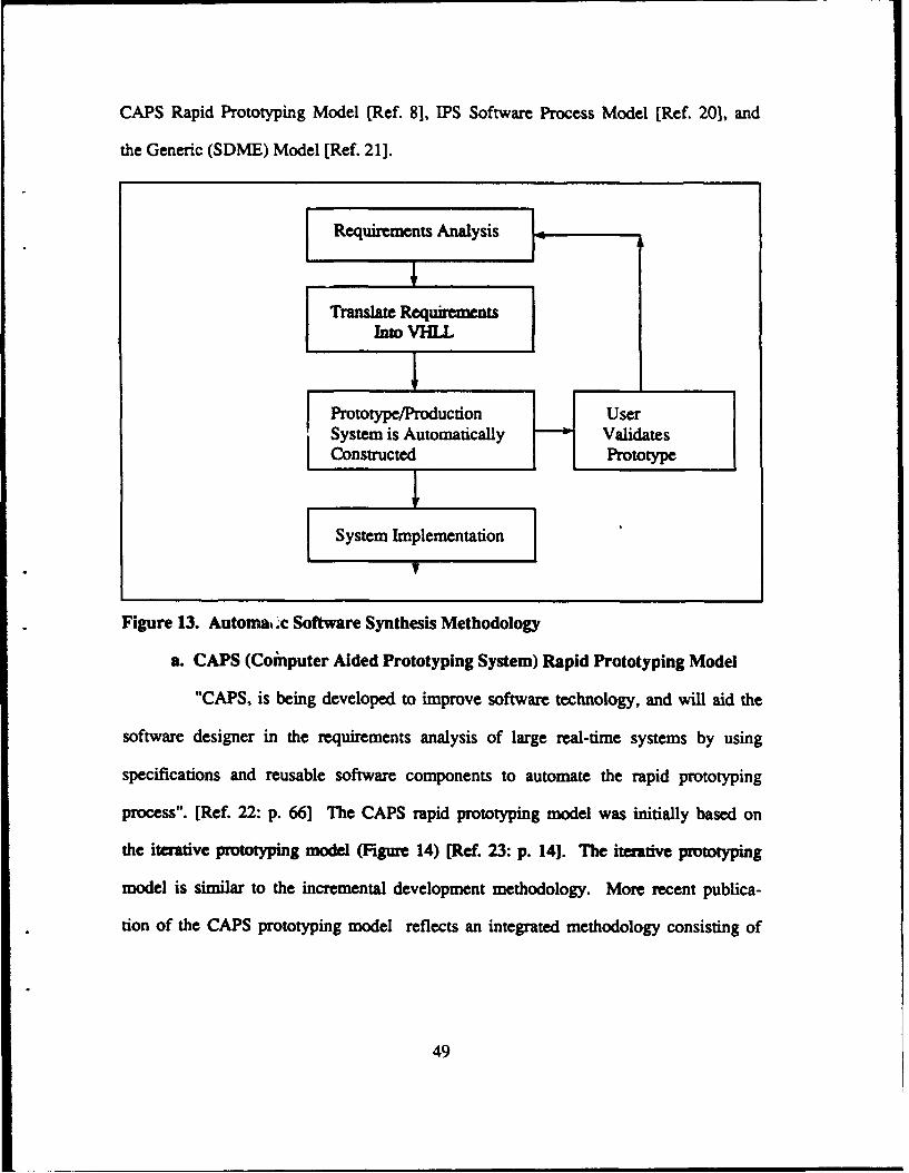
CAPS Rapid Prototyping Model [Ref. 81, IPS Software Process Model [Ref. 201, and
the Generic (SDME) Model [Ref. 21].
Requirements Analysis 7
Translate Requh n.Into WILL.
Prototype/Production UserSystem is Automatically ValidatesConstructed Prototype
System Implementation IFigure 13. Automak Xe Software Synthesis Methodology
a. CAPS (Coinputer Aided Prototyping System) Rapid Prototyping Model
"CAPS, is being developed to improve software technology, and will aid the
software designer in the requirements analysis of large real-time systems by using
specifications and reusable software components to automate the rapid prototyping
process". [Ref. 22: p. 66] The CAPS rapid prototyping model was initially based on
the iterative prototyping model (Figure 14) [Ref. 23: p. 14]. The iterative prototyping
model is similar to the incremental development methodology. More recent publica-
tion of the CAPS prototyping model reflects an integrated methodology consisting of
49
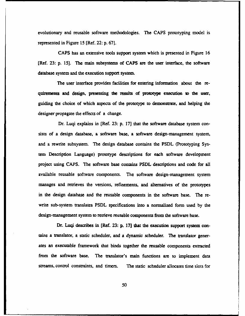
evolutionary and reusable software methodologies. The CAPS prototyping model is
represented in Figure 15 [Ref. 22: p. 671.
CAPS has an extensive tools support system which is presented in Figure 16
[Ref. 23: p. 15]. The main subsystems of CAPS are the user interface, the software
database system and the execution support system.
The user interface provides facilities for entering information about the re-
quirments and design, presenting the results of prottype execution to the user,
guiding the choice of which aspects of the prototype to demonstrate, and helping the
designer propagate the effects of a change.
Dr. Luqi explains in [Ref. 23: p. 17] that the software database system con-
sists of a design database, a software base, a software design-management system,
and a rewrite subsystem. The design database contains the PSDL (Prototyping Sys-
tem Description Language) prototype descriptions for each software development
project using CAPS. The software base contains PSDL descriptions and code for all
available reusable software components. The software design-management system
manages and retrieves the versions, refinements, and alternatives of the prototypes
in the design database and the reusable components in the software base. The re-
write sub-system translates PSDL specifications into a normalized form used by the
design-management system to retrieve reusable components from the software base.
Dr. Luqi describes in [Ref. 23: p. 17] that the execution support system con-
tains a translator, a static scheduler, and a dynamic scheduler. The translator gener-
ates an executable framework that binds together the reusable components extracted
from the software base. The translator's main functions are to implement data
streams, control constraints, and timers. The static scheduler allocates time slots for
50
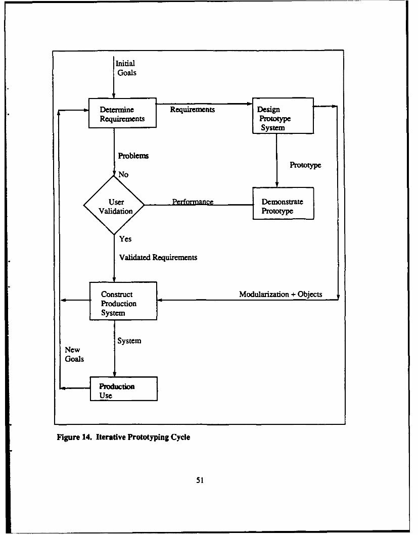
Goals
Prototype
Yes
Validated Requirements
NewGoals
PmdonUse
Figure 14. Iterative Prototyping Cycle
51
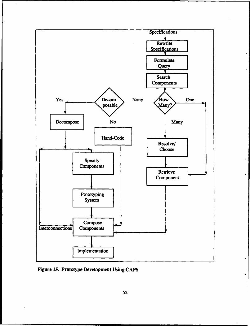
Specifications
S RewriteSpecifications
FormulateQuery
t
Search
= =I Choose
ComponentsetRetrieve/
CComponent
PrototypingSystem
ComposeInterconnections Components
Implementation
Figure 15. Prototype Development Using CAPS
52
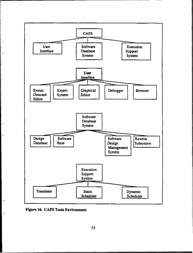
Dsign Software SotaExeriteInefneDatabaseBaeDsg Subyste
System
Figrecte. CASyose EvrnEnito
Edit53
operators with real-time constraints before execution begins. If the allocation suc-
ceeds, all operators are guaranteed to meet their deadlines, even with worst-case ex-
ecution times. As execution proceeds, the dynamic scheduler invokes operators with-
out real-time constraints in the time slots not used by operators with real-time con-
straints.
The Computer Aided Prototyping System is currently being developed and ex-
tensive research has been and is currently being conducted into all of the prototyping
tools, the PSDL language, and evaluations of the system with regard to advancing
computer technology. CAPS has been well documented in numerous publications, and
is the most clearly defined model of the currently published rapid prototyping models.
2. IPS (Integrated Prototyping System) Software Process Model
The IPS Software Process Model is currently being researched and implement-
ed at Southern Methodist University. The IPS model is based on the evolutionary
and reusable software components methodologies. "The model differs from the tradi-
tional approach in that it concentrates on the hard problems of system development,
namely; requirement specification and design rather than coding.
Equally important, validation, evaluation, and hardware/software trade-off analysis
are all part of the prototype development process". [Ref. 24: p. 101 The foundation for
the model is depicted in Figure 17 [Ref. 24: p. 9].
The prototyping process ik ocused around the software design phase. The re-
quirements analysis process does not change and the specifications phase changes
only to support the increased activity in the design phase. "The IPS model replaces
the software design phase of the traditional life cycle model with three phases: con-
structing a design, executing (testing) the design, and translating the design into a
54
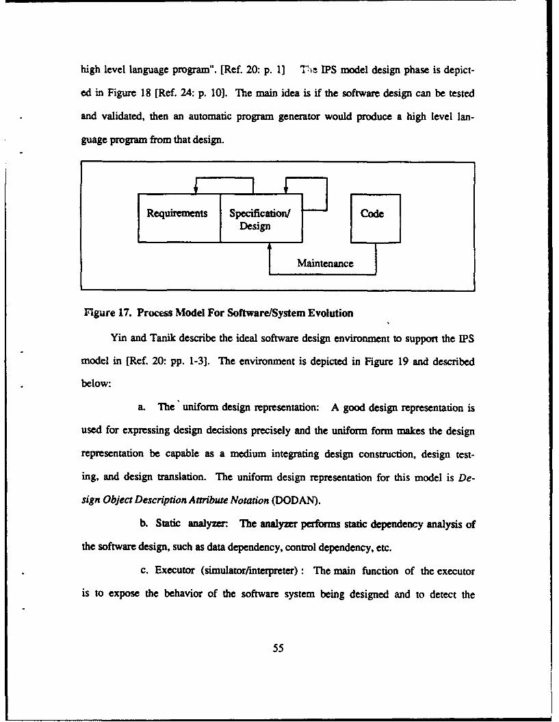
high level language program". [Ref. 20: p. 1] The IPS model design phase is depict-
ed in Figure 18 [Ref. 24: p. 10]. The main idea is if the software design can be tested
and validated, then an automatic program generator would produce a high level lan-
guage program from that design.
Requirements Specification/ CodeDesign
Maintenance
Figure 17. Process Model For Software/System Evolution
Yin and Tanik describe the ideal software design environment to support the IPS
model in [Ref. 20: pp. 1-3]. The environment is depicted in Figure 19 and described
below:
a. The uniform design representation: A good design representation is
used for expressing design decisions precisely and the uniform form makes the design
representation be capable as a medium integrating design construction, design test-
ing, and design translation. The uniform design representation for this model is De-
sign Object Description Attribute Notation (DODAN).
b. Static analyzer. The analyzer performs static dependency analysis of
the software design, such as data dependency, control dependency, etc.
c. Executor (simulator/mterpreter) : The main function of the executor
is to expose the behavior of the software system being designed and to detect the
55
design errors. Exposing system behavior in the design phase can provide users and
designers early feedback, reducing the cost of changes to implementation.
d. Automatic program generator : After testing the design, the desired
high level language program can be automatically generated from the design, the
design functionalities guaranteed to be reserved. Direct modification on code is
not necessary.
e. Design component base : The design component base management
stores and retrieves previously designed software components. Each design compo-
nent in the base is described in the uniform design representation. The design compo-
nent base management supports directly design maintenance and reusability.
f. User interface: The main function of a user interface is to provide
communication between the designer and the design environment. The user interface
offers the following facilities:
1. Design acquisition : The design acquisition consists of graphics
tools and editors (user friendly editors). The editors cooperate with the multiple
design representations and graphics tools, such as dataflow-oriented editor, state
machine-oriented editor, language-oriented syntax-directed editor, etc. All these
editors take different external design representations as inputs and convert them into
the uniform design representation. The designer can choose an editor supporting the
design methodology he is familiar with.
2. Testing display: The testing display shows the prototype execu-
tion or the interpretation of the design. The display may be a time chart indicating the
system state changes or the desired system behavior like dialogue, input/output, etc.
56
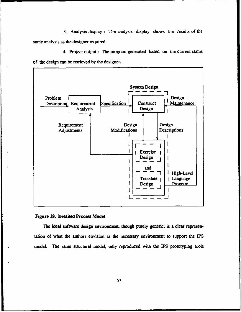
3. Analysis display : The analysis display shows the results of the
static analysis as the designer required.
4. Project output : The program generated based on the current status
of the design can be retrieved by the designer.
System Design
Problem FIDsgDescription Requirement Specfication Construct Maintenance-IAnalysis -1Design
Requirement Design I DesignAdjustments Modifications Descriptions
fn- I I
I Exercise IL Design _.j
andand High-Level
Translate I Language
Design _] Pmrnm
I - I
L~~
Figure 1& Detailed Process Model
The ideal software design enviroment, though purely generic, is a clear represen-
tation of what the authors envision as the necessary environment to support the IPS
model. The same structural model, only reproduced with the IPS prototyping tools
57
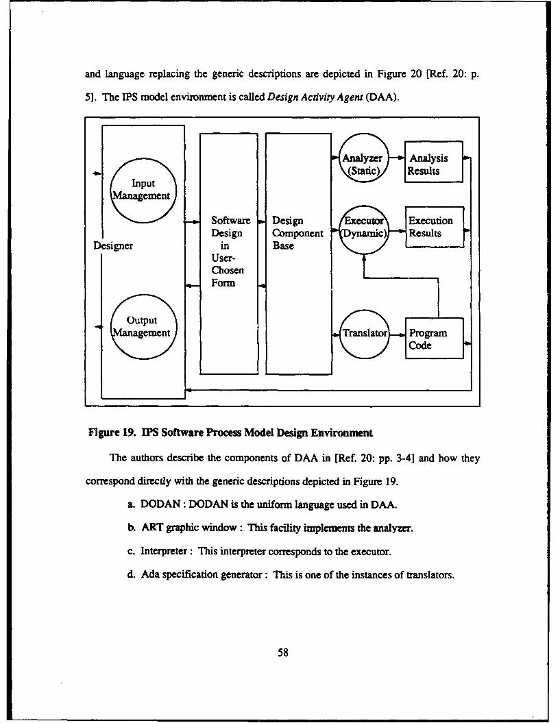
and language replacing the generic descriptions are depicted in Figure 20 [Ref. 20: p.
5]. The IPS model environment is called Design Activity Agent (DAA).
(Iput\\~ngementJ
Software Design eur ExecutionDesign Component *c) Results
Designer in BaseUser-ChosenForm
outputagemnent Tasao rga
Figure 19. IPS Software Process Model Design Environment
The authors describe the components of DAA in [Ref. 20: pp. 3-41 and how they
correspond directly with the generic descriptions depicted in Figure 19.
a. DODAN: DODAN is the uniform language used in DAA.
b. ART graphic window: This facility implements the analyzer.
c. Interpreter : This interpreter corresponds to the executor.
d. Ada specification generator: This is one of the instances of translators.
58
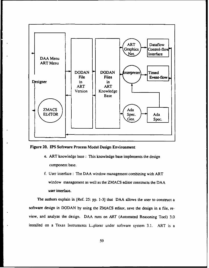
ART Dataflow
G\raphicsJ -Cnt'ol-flo "Ne Intrfc
DAA MenuART Menu
DODAN DODAN tTimedFile Files Event-flow
Dsigner in inART ART
Version Knowledge" Base
ZMACSAdEDITORS
Figure 20. PS Software Process Model Design Environment
e. ART knowledge base: This knowledge base implements the design
component base.
f. User interface : The DAA window management combining with ART
window management as well as the ZMACS editor constructs the DAA
user interface.
The authors explain in [Ref. 25: pp. 1-3] that DAA allows the user to construct a
software design in DODAN by using the ZMACS editor, save the design in a file, re-
view, and analyze the design. DAA runs on ART (Automated Reasoning Tool) 3.0
installed on a Texas Instruments L;,plorer under software system 3.1. ART is a
59
software tool-kit for building expert systems, and has three major components: ART
language, ART inference engine, and ART programming environment. The software
information is represented in either frames or rules, the hierarchical structure viewed,
manipulation of software information by firing rules, saving, and retrieving the soft-
ware information.
The majority of effort expended thus far in research and implementation of the IPS
model is focused on the design phase. The proceyping prcss is separated into two
phases. The first phase is to prototype the design by using DAA, and then construct-
ing a prototype using the automatic program generator. The design prototype process
is explicitly defined in [Ref. 20] and (Ref. 25]. The process of how the executable pro-
totype will be developed is still being researched and is not currently defined. It can
be inferred from the description of DAA that a complete set of requirements could be
prototyped since the transformation of design-level code to high level programming
code is unlikely to be discriminant.
3. Generic (SDME) Model
The Generic (SDME) Model is based on the premise that there are few concep-
tual differences between the traditional Waterfall Life Cycle Model and the proposed
rapid prototyping paradigm. Instead the two models are merely seen as different ap-
proaches to accomplishing the same end. The Generic Model is presented in Figure
21 [Ref. 21: p. 151.
The Generic Model divides the traditional Waterfall Model into generic phases.
The development portion of the model consists of the generic phases, analysis, de-
sign, and implementation. The management and support functions are generally
grouped independently as maintenance, retirement, project management, and quality
60
assurance. The development portion is further broken down into two domains, prob-
lem and solution (Figure 22) [Ref. 21: p. 15].
The generic structured development method is illustrated in Figure 23 [Ref. 21:
p. 15]: the primary work flow occurs from left to right. Analysis is a decomposition
process. Basic objects and transforms are defined in the problem domain. Then these
objects and transforms are decomposed to a sufficient level of specificity that allows
the desired behavior within the problem domain to be defned. "Each method has a
different approach towards developing the set of symbols with which to define the
problem, but the methods all converge on several classes of generic deliverables at
the end of the analysis". [Ref. 21: p. 15]
Tyron points out in [Ref. 21: p. 151 that all development methods deliver some
form of a static model of the problem domain which describes and'defines the objects
and the relationships within the problem domain. Analysis also creates a dynamic
model which describes the permissible behavior of the objects within the problem do-
main. The behaviors or transforms are also defined in terms of the symbols devel-
oped in the static model. Examples of portions of the dynamic model are data flow dia-
grams and state transition diagrams.
Tyron claims in [Ref. 21: p. 16] that design is a process of architecture and syn-
thesis. Design takes the products of analysis, the static, dynamic, and constraint
models, and attempts to build a class of solutions to the defined problem. It repre-
sents the point of shift from a problem-oriented perspective to a solution-oriented
perspective.
61
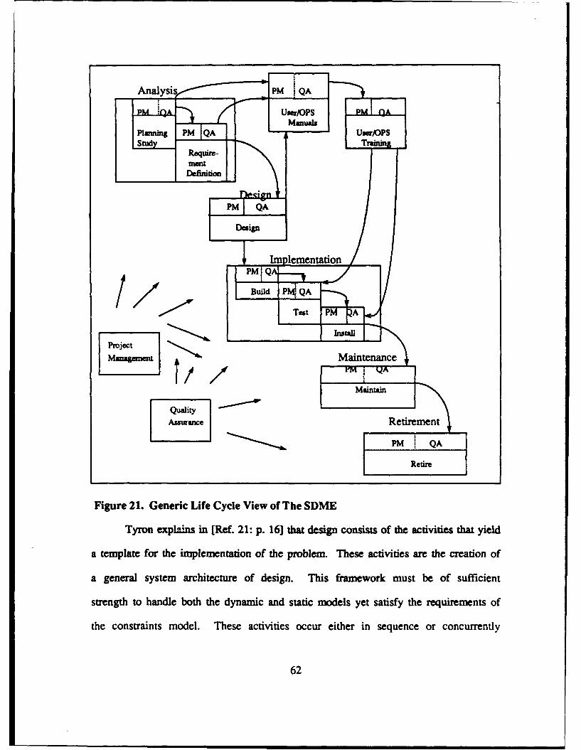
Analysi 1M i QA
Planningt PM QA 6- .OP
S4Y Rer- TReil
Require-
Figure 21. Generic Life Cycle View of The SDME
Tyron exp lains in [Ref. 21: p. 16] that design consists of the activities that yield
a template for the implementation of the problem. These activities are the creation of
a general system architecture of design. This framework must be of sufficient
strength to handle both the dynamic and static models yet satisfy the requirements of
the constraints model. These activities occur either in sequence or concurrently
62
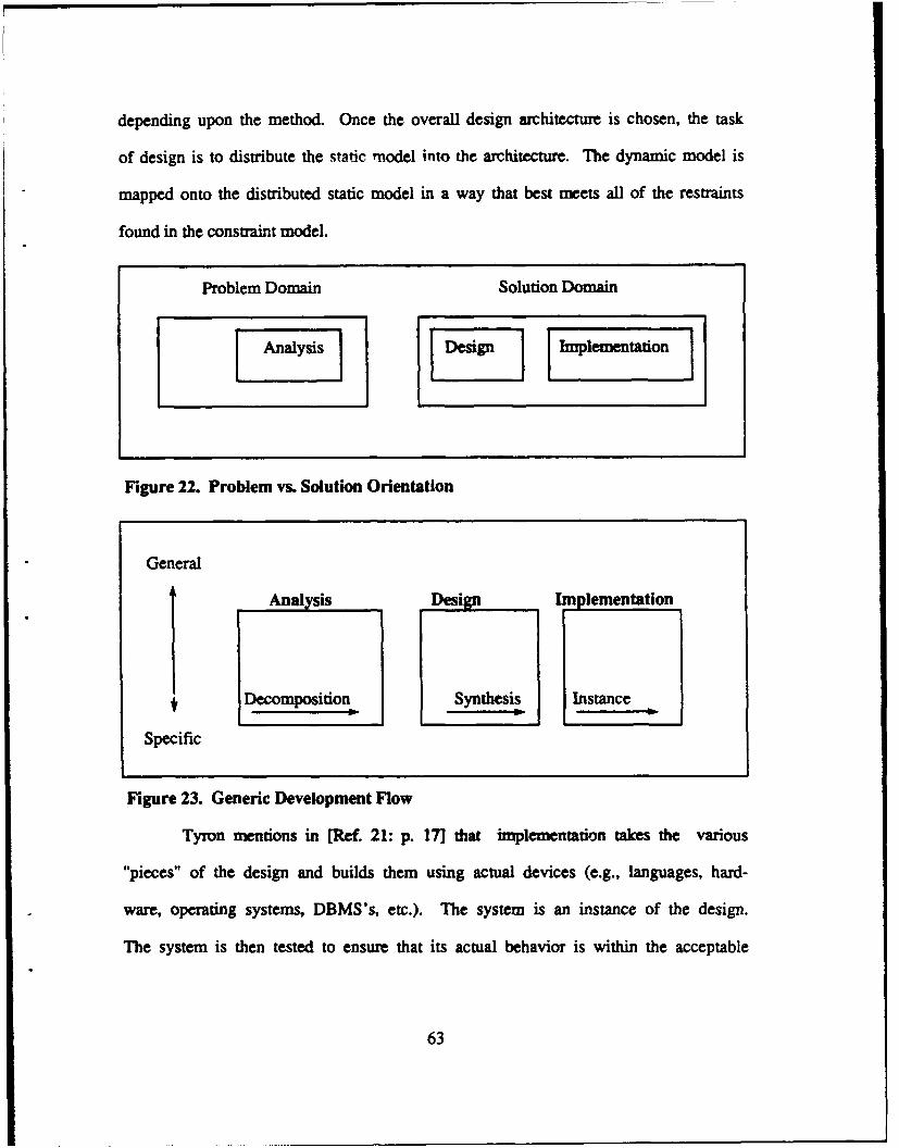
depending upon the method. Once the overall design architecture is chosen, the task
of design is to distribute the static model into the architecture. The dynamic model is
mapped onto the distributed static model in a way that best meets all of the restraints
found in the constraint model.
Problem Domain Solution Domain
Figure 22. Problem vs. Solution Orientation
General
Analysis Design Implementation
Decomposition Synthesis Instance
Specific
Figure 23. Generic Development Flow
Tyron mentions in [Ref. 21: p. 171 that implementation takes the various
"pieces" of the design and builds them using actual devices (e.g., languages, hard-
ware, operating systems, DBMS's, etc.). The system is an instance of the design.
The system is then tested to ensure that its actual behavior is within the acceptable
63
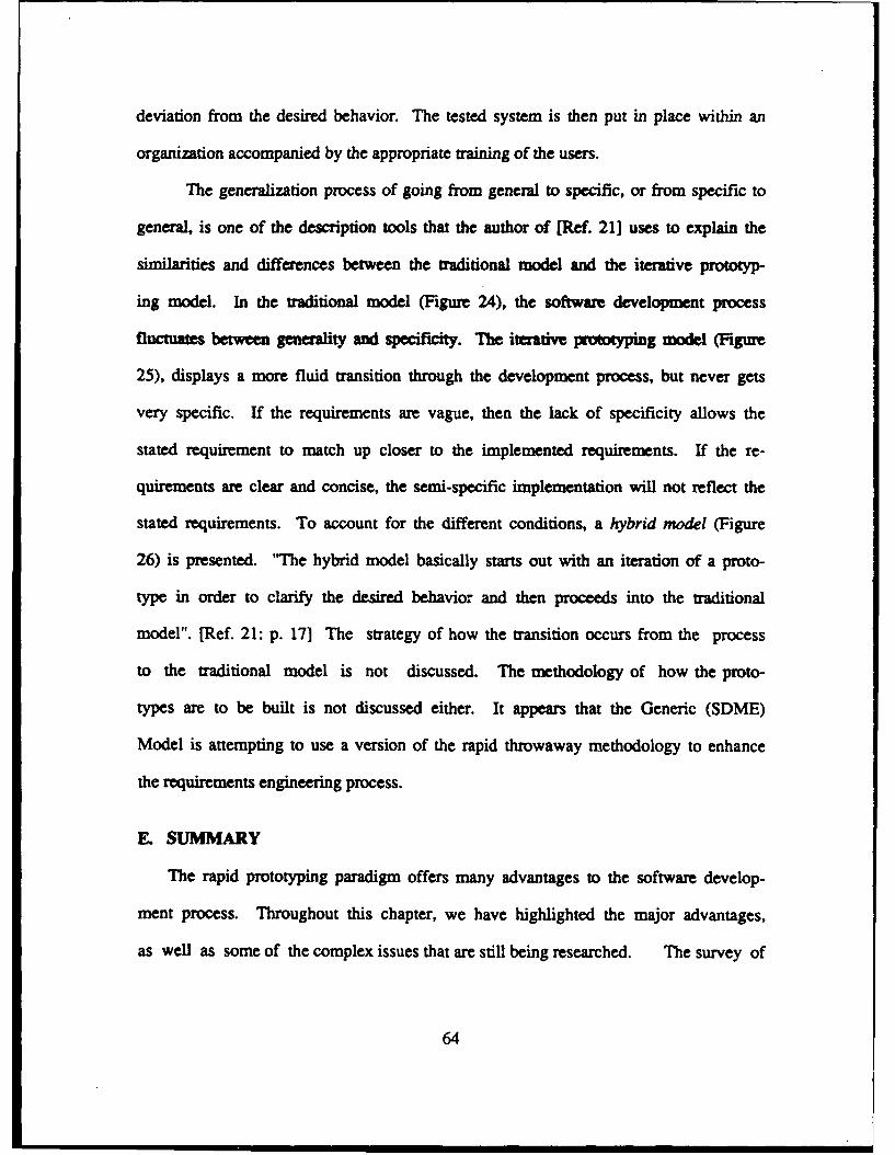
deviation from the desired behavior. The tested system is then put in place within an
organization accompanied by the appropriate training of the users.
The generalization process of going from general to specific, or from specific to
general, is one of the description tools that the author of [Ref. 21] uses to explain the
similarities and differences between the traditional model and the iterative prototyp-
ing model. In the traditional model (Figure 24), the software development process
fluctuates between generality and specificity. The iteative prototyping model (Figure
25), displays a more fluid transition through the development process, but never gets
very specific. If the requirements are vague, then the lack of specificity allows the
stated requirement to match up closer to the implemented requirements. If the re-
quirements are clear and concise, the semi-specific implementation will not reflect the
stated requirements. To account for the different conditions, a hybrid model (Figure
26) is presented. '"he hybrid model basically starts out with an iteration of a proto-
type in order to clarify the desired behavior and then proceeds into the traditional
model". [Ref. 21: p. 17] The strategy of how the transition occurs from the process
to the traditional model is not discussed. The methodology of how the proto-
types are to be built is not discussed either. It appears that the Generic (SDME)
Model is attempting to use a version of the rapid throwaway methodology to enhance
the requirements engineering process.
E. SUMMARY
The rapid prototyping paradigm offers many advantages to the software develop-
ment process. Throughout this chapter, we have highlighted the major advantages,
as well as some of the complex issues that are still being researched. The survey of
64
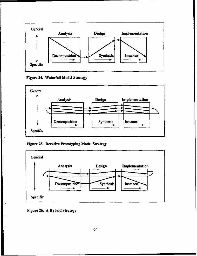
GeneralAnalysis Design Implementation
Specific
Figure 24. Waterfall Model Strategy
General
Analysis____ Design___ Implementation
Specific
Figure 25. Iterative Prototyping Model Strategy
General
AnalysisDesig Implementation
Specific
Figure 26. A Hybrid Strategy
65
the methodologies revealed a progressive means of implementing the rapid prototyp-
ing paradigm. Some of the methodologies are capable of being implemented now,
while others require more research and advances in technology to permit implementa-
tion. Two of the surveyed rapid prototyping models, CAPS Rapid Prototyping Model
[Ref. 8] and IPS Software Process Model [Ref. 20], display conceptually similar de-
sign features, while the Generic Model [Ref. 21], is more conventional in its ap-
proach. The survy of the models revealed that regardless of how diverse the ap-
proaches are to implementing rapid prototyping, they all require more research and
are "slow" in development.
66
I. EVALUATION OF PROPOSED RAPID PROTOTYPING
METHODOLOGIES
Since the rapid prototyping paradigm is still relatively new , an evaluation of alter-
native software life cycle methodologies and models is necessary for a few reasons.
One reason is to determine if recent research proposals ffl fte ats and
goals of the new paradigm. Another reason is to determine what is achievable now
and what will be achievable with future advances in computer technology. The third
reason is to provide a baseline from which recommendations can be made on how to
manage rapid prototyping to meet DoD's software development needs. It should be
noted that these reasons are not an exhaustive list, but do capture the intent of this
thesis.
The evaluations of the methodologies and models require different evaluation crite-
ria from each other.• The evaluation criteria for the methodologies will be focused on
how well they meet the strategic goals of the proposed paradigm. The evaluation cri-
teria are 1) prototype development, 2) use of reusable software components, 3) evolu-
tionary prototype production, 4) meeting user needs, 5) time, activities, and effort,
and 6) implementation outlook. Some of the evaluation criteria for the methodologies
cannot be evaluated because there are no detailed descriptions.
A. EVALUATION CRITERIA DESCRIPTIONS
Prior to evaluating the rapid prototyping methodologies, the evaluation criteria need
to be more clearly defined. Since the methodologies are strategic descriptions of how
67
to implement the new paradigm, the evaluation criteria is focused on their respective
design features.
Prototype development : This criterion addresses the efficiency with which the
prototype is constructed and the effect the prototype has on requirements engineer-
ing. This criteria also addresses the effect the methodology has on the ability of us-
ers to validate the stated requirements as well as the changing requirements.
Use of reusable software components : This crimri addresses whether the
methodology encourages the use of reusable software components in its prototype
construction. The criteria also addresses whether the production system is manually
coded or whether the use of reusable software components encouraged.
Evolutiony prototypeproduction : This criterion addresses whether the de-
veloped prototype results in a production system or is used primarily for the purpose
of validating requirements in the requirements engineering process.
Meeting user needs : This criterion evaluates how well the methodology meets
user needs with respect to on-time delivery and meeting the user requirements. This
approach to evaluating the methodologies was presented in [Ref. 51 and [Ref. 7].
The experimental data to support this evaluation is anticipatory rather than factual,
but it does provide an interesting perspective on how the methodologies might per-
form in relation to user needs.
The user needs are evolutionary and increase over time. A representation of the
user's needs is presented in Figure 27 [Ref. 5: p. 1455]. The authors note in
[Ref. 7: p. 4] that although these needs ae shown as a linear function, in actuality,
the function is neither linear or continuous. The time scale on the x-axis should be
68
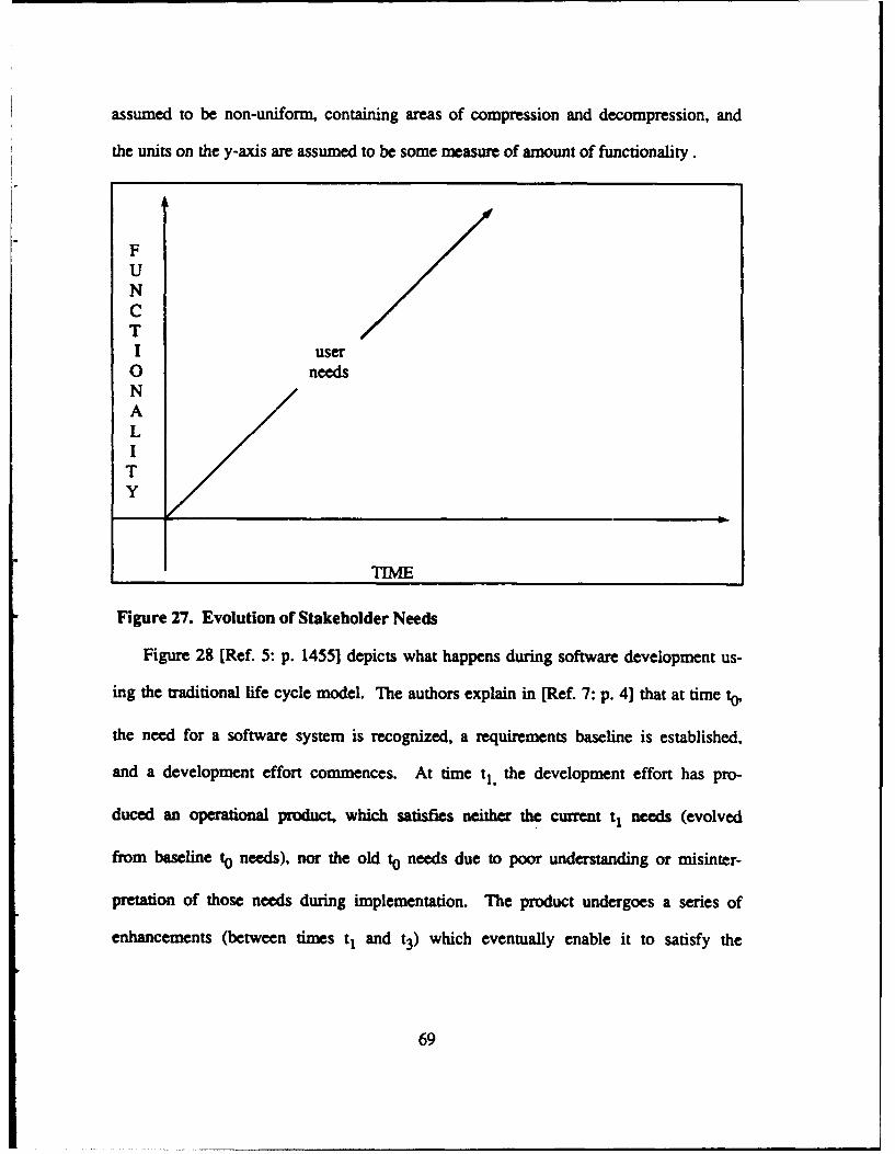
assumed to be non-uniform, containing areas of compression and decompression, and
the units on the y-axis are assumed to be some measure of amount of functionality.
FUNCTI user0 needsNALI
TY
Figure 27. Evolution of Stakeholder Needs
Figure 28 [Ref. 5: p. 1455] depicts what happens during software development us-
ing the traditional life cycle model. The authors explain in [Ref. 7: p. 4] that at time to,
the need for a software system is recognized, a requirements baseline is established,
and a development effort commences. At time tj, the development effort has pro-
duced an operational product, which satisfies neither the current tj needs (evolved
from baseline to needs), nor the old to needs due to poor understanding or misinter-
pretation of those needs during implementation. The product undergoes a series of
enhancements (between times tj and t3) which eventually enable it to satisfy the
69
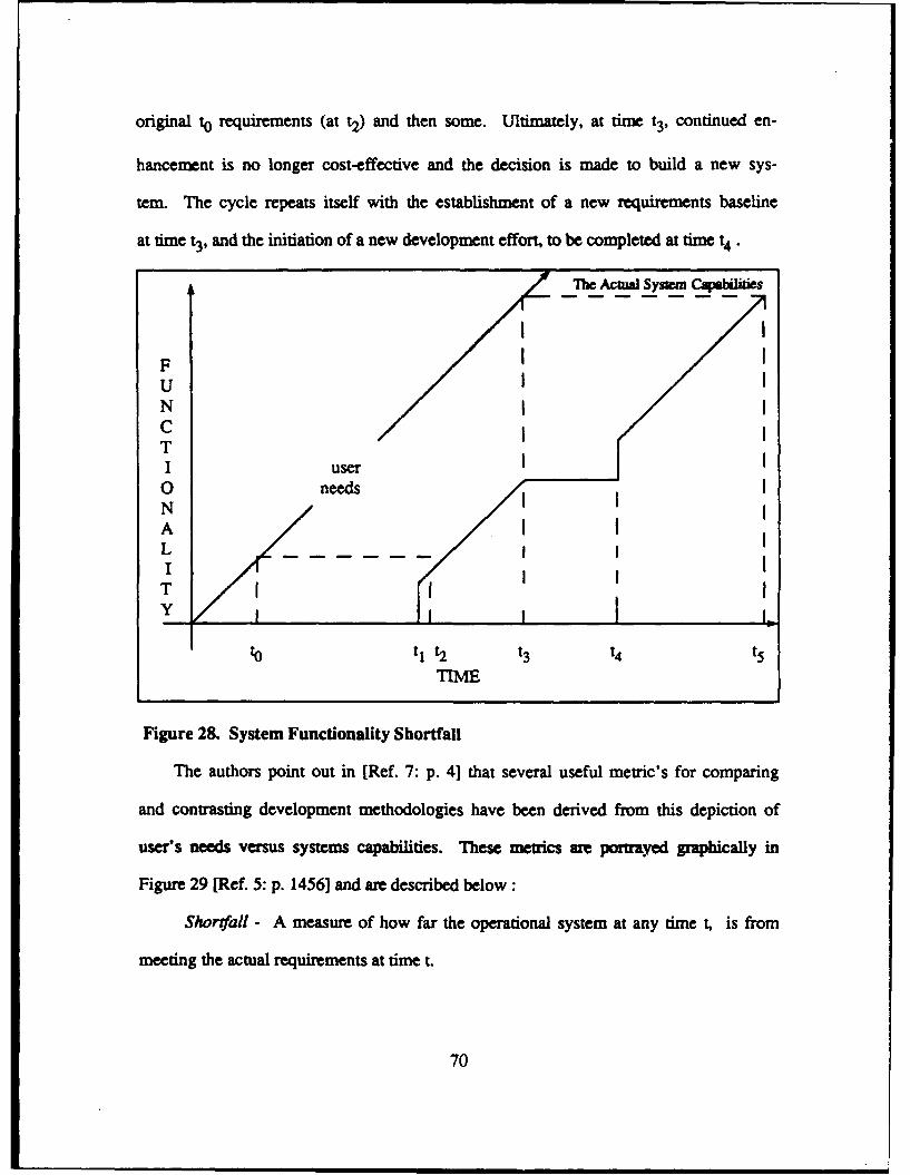
original to requirements (at t2) and then some. Ultimately, at time t3, continued en-
hancement is no longer cost-effective and the decision is made to build a new sys-
tem. The cycle repeats itself with the establishment of a new requirements baseline
at time t3 , and the initiation of a new development effort, to be completed at time t4 .
The AcuW Sysm ...
II
FUNC /iT
I user0 needsN IA I
T I
to t t2 t3 t4 t5TIME
Figure 28. System Functionality Shortfall
The authors point out in [Ref. 7: p. 4] that several useful metric's for comparing
and contrasting development methodologies have been derived from this depiction of
user's needs versus systems capabilities. These metrics are portrayed graphically in
Figure 29 [Ref. 5: p. 1456] and are described below :
Shortfall - A measure of how far the operational system at any time , is from
meeting the actual requirements at time t.
70
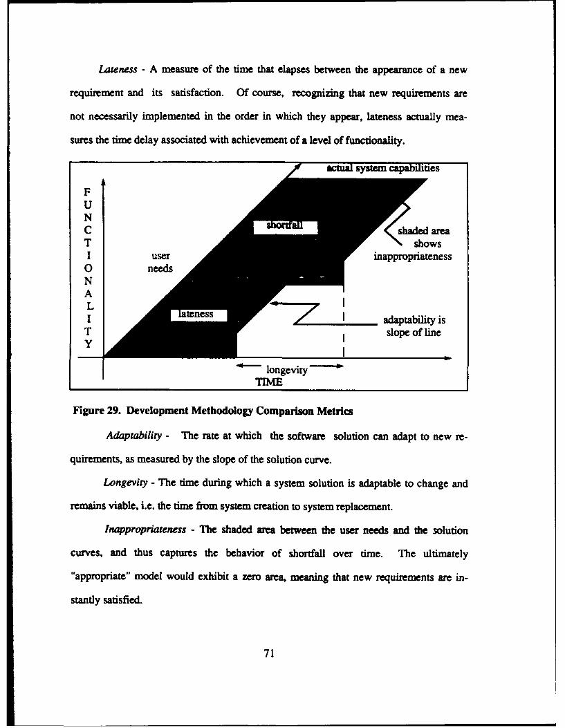
Lateness - A measure of the time that elapses between the appearance of a new
requirement and its satisfaction. Of course, recognizing that new requirements are
not necessarily implemented in the order in which they appear, lateness actually mea-
sures the time delay associated with achievement of a level of functionality.
acua system capabilities
FUNC areaT shows
I userl inappropriateness0 needsNALI teness L adaptability isT slope of lineTyI
longevityTIME
Figure 29. Development Methodology Comparison Metrics
Adaptability - The rate at which the software solution can adapt to new re-
quirements, as measured by the slope of the solution curve.
Longevity - The time during which a system solution is adaptable to change and
remains viable, i.e. the time from system creation to system replacement.
Inappropriateness - The shaded area between the user needs and the 3olution
curves, and thus captures the behavior of shortfall over time. The ultimately
"appropriate" model would exhibit a zero area, meaning that new requirements are in-
standy satisfied.
71
Time, activities, and effort : This criterion evaluates a three-dimensional view
of the software development process with respect to time, activities, and effort ex-
pended. This evaluation criteria was also presented in [Ref. 5] and [Ref. 7]. It too
lacks the experimental data, but the essence of the evaluation focuses on each stage
of development.
In the traditional life cycle model, the step-by-step or stage-by-stage refinement
process gives the impression of being one-dimensional and oriented only on tie.
Figure 30 provides a single dimension view of the traditional life cycle model [Ref. 7:
p. 2]. "This one-dimensional interpretation has been carried forth into DoD software
development standards, industry standards, technical writings, reference books, ard
attempted application to software projects". [Ref. 7: p. 21 The problem with a one-di-
mensional view of software development is that the dynamic nature of the process is
not necessarily a step-wise refinement. Each phase or sub-process, which is inher-
ent to any of the methodologies, remains ongoing throughout the process until the
software is retired or replaced.
To better see the overlapping of the phases or sub-processes, a two-dimensional
perspective of the software process is helpful. Figure 31 shows a two-dimen-
sional view of the traditional life cycle model [Ref. 7: p. 2]. The activities and time
perspective on two adjacent axes provides a clear perspective of how the different ac-
tivities interact and the relationships between these activities and time. The shaded
areas represent the activity in each stage with respect to time.
The authors claim in [Ref. 7: pp. 2-31 that by using this model, other activities
such as planning , quality assurance, configuration management, and test and evalua-
tion, that occur during a systems lifetime can be more appropriately labeled.
72
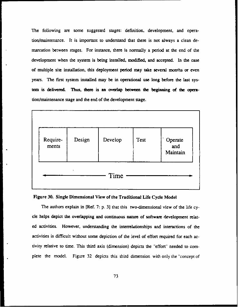
The following are some suggested stages: definition, development, and opera-
tion/maintenance. It is important to understand that there is not always a clean de-
marcation between stages. For instance, there is normally a period at the end of the
development when the system is being installed, modified, and accepted. In the case
of multiple site installation, this deployment period may take several months or even
years. The first system installed may be in operational use long before the last sys-
tem is delivered. Thus, there is an overlap between the beginning of the opera-
tion/maintenance stage and the end of the development stage.
Require- Design Develop Test Operatements and
Maintain
Time
Figure 30. Single Dimensional View of the Traditional Life Cycle Model
The authors explain in [Ref. 7: p. 3] that this two-dimensional view of the life cy-
cle helps depict the overlapping and continuous nature of software development relat-
ed activities. However, understanding the interrelationships and interactions of the
activities is difficult without some depiction of the level of effort required for each ac-
tivity relative to time. This third axis (dimension) depicts the "effort" needed to com-
plete the model. Figure 32 depicts this third dimension with only the "concept of
73
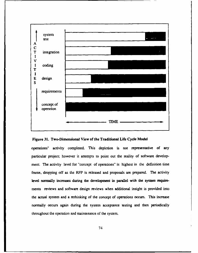
systemtest
ACT integrationIVI codingTI
E designS
requirements
concept of
operation
, TIME
Figure 31. Two-Dimensional View of the Traditional Life Cycle Model
operations" activity completed. This depiction is not representative of any
particular project; however it attempts to point out the reality of software develop-
ment. The activity level for "concept of operations" is highest in the definition time
frame, dropping off as the RFP is released and proposals are prepared. The activity
level normally increases during the development in parallel with the system require-
ments reviews and software design reviews when additional insight is provided into
the actual system and a rethinking of the concept of operations occurs. This increase
normally occurs again during the system acceptance testing and then periodically
throughout the operation and maintenance of the system.
74
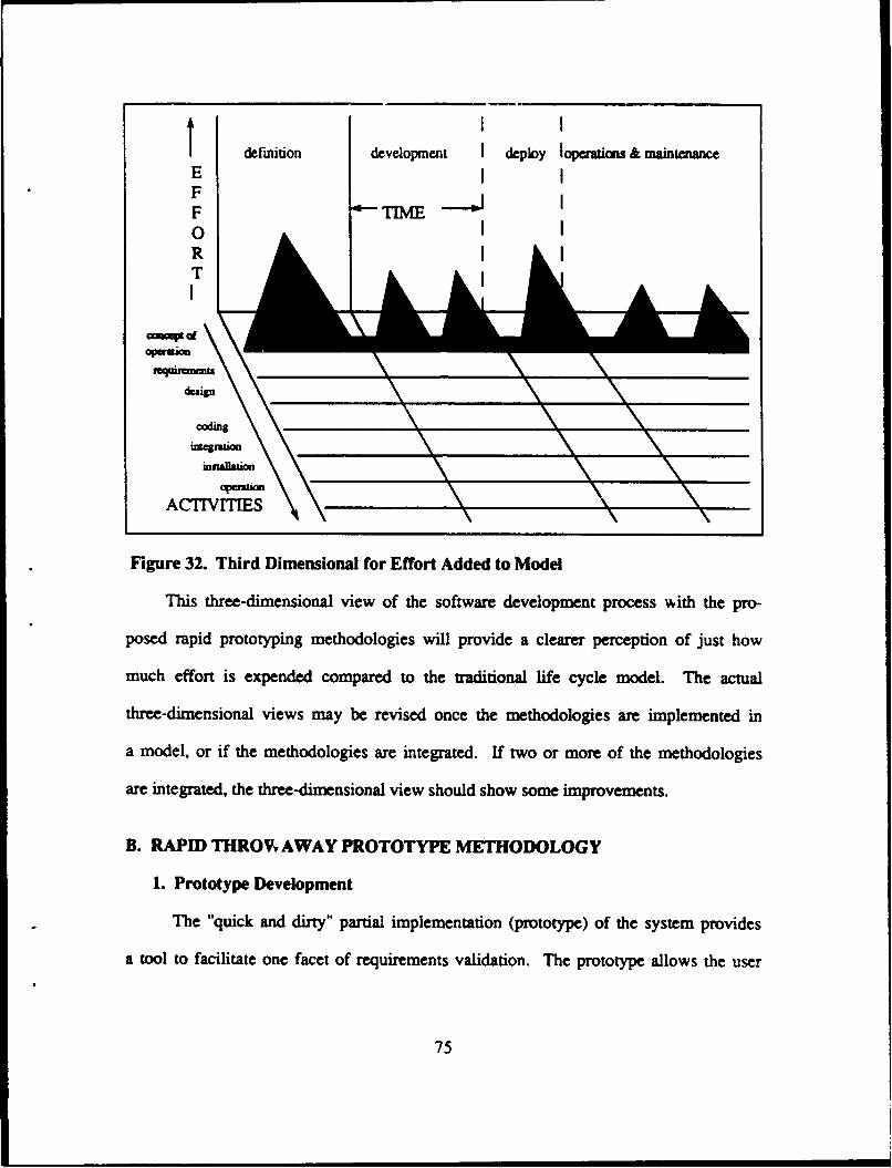
SI I
def'miion development deploy IopeWions & maintanEFF T "0RTII
,a a\
coding
ACTVITIES
Figure 32. Third Dimensional for Effort Added to Model
This three-dimensional view of the software development process with the pro-
posed rapid prototyping methodologies will provide a clearer perception of just how
much effort is expended compared to the traditional life cycle model. The actual
three-dimensional views may be revised once the methodologies are implemented in
a model, or if the methodologies are integrated. If two or more of the methodologies
are integrated, the three-dimensional view should show some improvements.
B. RAPID THROW AWAY PROTOTYPE METHODOLOGY
1. Prototype Development
The "quick and dirty" partial implementation (prototype) of the system provides
a tool to facilitate one facet of requirements validation. The prototype allows the user
75
to validate a partial set of the requirements. The construction of the prototype is not
as well defined, which leads to some concerns about the usefulness of the methodolo-
gy.
The authors in [Ref. 7: p. 5] claim that the requirements engineering process dif-
fers slightly from the traditional life cycle model in that the prototype is constructed to
allow the user the opportunity to validate some of the requirements early in the soft-
wa developmen process and give the developers the confidence that they we build-
ing the "right" system.
The partial set of requirements would imply that a small-scale prototype, one
which represents user-interface features and possibly limited implementation fea-
tures, would meet the intent of the methodology. However, it was noted in Chapter II
that the more complex a system gets and the more interactions between major func-
tions and modules, the more susceptible the system is to rippling effects. With this
in mind, there are concerns over whether the prototype will truly represent the sys-
tem as it will look and act upon implementation. Surely, the prototype will be unable
to represent the real-time constraints of the system. Therefore, the usefulness of
this prototyping methodology for large real-time systems is suspect.
Given a small-scale system, or a simple large scale system in which implemen-
tation is not very complex, the methodology could be useful. The rapidly constructed
prototype would allow users to validate whatever requiremnts they feel are most im-
portant. If the users are concerned about user-interface features (i.e., screen dis-
plays, windows, icons, etc.), then the prototype could serve as a useful validation
tool.
76
If the user wants a prototype of a complex requirement or a representation of an
integrated set of requirements, then the prototype does not make much sense. The
prototype is only a partial version of the system, therefore it is not detailed enough to
give users a true representation of performance. Another aspect is that the prototype
is not used in the production system, and designers would rather devote the time to
coding the complex requirements than in developing a partial prototype. So for small-
scale systems or dominant user-interface systems, the methodology has some merit.
Given a clear and concise set of requirements that would remain static over the period
of development, then the rapid throwaway prototype is useful. But as discussed in
earlier chapters, this is a rarity rather than the norm.
The discussion of the home building industry in Chapter I1 probably best explains
this methodology. The small-scale model that architects and designers construct is
to allow potential home-owners the opportunity to see what the home will look like
when completed. The scaled down model is not detailed to the point of showing every
feature, but only features that the architects feel are most important to the potential
home-owners. Another similarity is that none of the model will be used to construct
the house. If the potential home-owners want a different style roof or front window,
the architect will note the enhancement and include it in the design of the home. But
neither the restructured roof or front window of the model will go onto the constructed
home. Once the scaled-down model is approved, the changes to the architectural
plans are made and the model is not used again. A similar process is used in this
methodology where the scale model corresponds to the prototype, the architect corre-
sponds to the software designer, and the potential home-owners with the users.
77
2. Use of Reusable Software Components
The methodology of constructing a "quick and dirty" prototype assumes that
the prototype could be manually coded. The methodology does not treat reusable
software components as a necessary feature. However, if reusable software compo-
nents were utilized in the construction of the prototype, then the "quick" part of the
process would be enhanced. Since none of the code from the prototype will be used in
the production system, the often confusing task of mdslaing previously written code
is not a problem.
It would be very inefficient to spend the time manually coding the prototype, and
then not use it again as production coding. So if this methodology is to be utilized and
be as efficient as possible, the use of reusable components would appear to be a nec-
essary enhancement.
3. Evolutionary Prototype Production
The title of this methodology implies that evolutionary prototype production is
not an issue. The prototype is not intended to be used beyond the requirements anal-
ysis phase of the requirements engineering process. This may seem inefficient
considering the entire software development process, but it does enhance the require-
ments engineering process of the traditional life cycle model. Unfortunately, because
it is not evolutionary, the problem of the dynamic stages that software development
go through, the enhancements gained early in the process could be overrun by the
changes later in the process.
4. Meeting User Needs
This methodology makes some strides in closing the gap of "inappropriateness"
in the traditional life cycle model. Figurc 33 represents the theoretical gap between
78
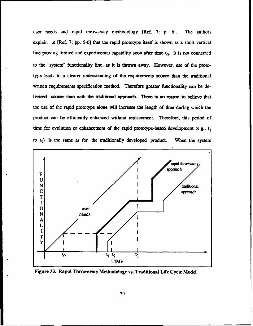
user needs and rapid throwaway methodology [Ref. 7: p. 6]. The authors
explain in [Ref. 7: pp. 5-61 that the rapid prototype itself is shown as a short vertical
line proving limited and experimental capability soon after time to . It is not connected
to the "system" functionality line, as it is thrown away. However, use of the proto-
type leads to a clearer understanding of the requirements sooner than the traditional
written requirements specification method. Therefore greater functionality can be de-
livered sooner than with the mtitional approach. There is no reason to believe that
the use of the rapid prototype alone will increase the length of time during which the
product can be efficiently enhanced without replacement. Therefore, this period of
time for evolution or enhancement of the rapid prototype-based development (e.g., tj
to t3) is the same as for the traditionally developed product. When the system
rapid throwawayapproach
FUN IsiioaC approachTI0 userN needsALIT
ti t2 t3
TINE
Figure 33. Rapid Throwaway Methodology vs. Traditional Life Cycle Model
79
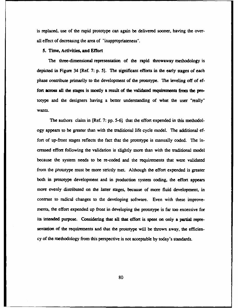
is replaced, use of the rapid prototype can again be delivered sooner, having the over-
all effect of decreasing the area of "inappropriateness".
S. Time, Activities, and Effort
The three-dimensional representation of the rapid throwaway methodology is
depicted in Figure 34 [Ref. 7: p. 5]. The significant efforts in the early stages of each
phase contribute primarily to the development of the prototype. The leveling off of ef-
fort aross all the stages is mostly a result of the validated .equiruents from the pro-
totype and the designers having a better understanding of what the user "really"
wants.
The authors claim in [Ref. 7: pp. 5-6] that the effort expended in this methodol-
ogy appears to be greater than with the traditional life cycle model. The additional ef-
fort of up-front stages reflects the fact that the prototype is manually coded. The in-
creased effort following the validation is slightly more than with the traditional model
because the system needs to be re-coded and the requirements that were validated
from the prototype must be more strictly met. Although the effort expended is greater
both in prototype development and in production system coding, the effort appears
more evenly distributed on the latter stages, because of more fluid development, in
contrast to radical changes to the developing software. Even with these improve-
ments, the effort expended up front in developing the prototype is far too excessive for
its intended purpose. Considering that all that effort is spent on only a partial repre-
sentation of the requirements and that the prototype will be thrown away, the efficien-
cy of the methodology from this perspective is not acceptable by today's standards.
80
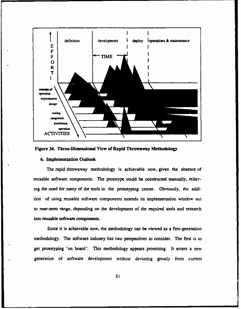
definition development I deploy loperations & mainteumnce
E I IFF TIME
Figure 34. Three-Dimensional View of Rapid Throwaway Methodology
6. Implementation Outlook
The rapid throwaway methodology is achievable now, given the absence of
reusable software components. The prototype could be constructed manually, reliev-
ing the need for many of the tools in the prozotyping center. Obviously, the addi-
tion of using reusable software components extends its implementation window out
to near-term range, depending on the development of the required tools and research
into reusable software components.
Since it is achievable now, the methodology can be viewed as a first-generation
methodology. The software industry has two perspectives to consider. The first is to
get prototyping "on board". This methodology appears promising. It enters a new
generation of software development without deviating greatly from current
81
development practices. So from this perspective, the hard-line, experienced software
developers would be more comfortable with introduction of this methodology. On the
other hand, the excessive effort that needs to be expended may turn away some de-
velopers that are skeptical of the prototyping paradigm in the first place. It is not logi-
cal to accept the extra work required just to get a partial set of requirements validat-
ed early. It is primarily the developers that can't see the forest for the trees, that will
criticize this methodology and probably will lobby hard for its abolishment. If it is in-
troduced as a first-generation prototyping methodology, the point needs to be made
that rapid throwaway is only an initial representation of the new rapid prototyping
paradigm and will serve to remedy some of the existing problems associated with the
traditional life cycle model.
C. INCREMENTAL DEVELOPMENT METHODOLOGY
1. Prototype Development
The incremental development methodology accomplishes everything that the
rapid throwaway methodology does, only in more detail and more efficiently.
The incremental process of representing the most difficult requirements first, followed
by the simpler ones provides the users with a better perspective of how the system
will look upon delivery. Whether it is more efficient to start with the more difficult re-
quirements first, or with the simpler ones, is subject to debate and is primarily depen-
dent on the complexity of the system and the expertise of the developers. It is unlike-
ly that the computer science community will ever agree on this subject, so any effort
expended here would be meaningless. But the systematic prototype development
82
process of starting at one extreme and working towards the other is an enhancement
to the rapid throwaway methodology.
The level of detail that the prototype will be able to represent also enhaices the
requirements validation process. The user is provided the opportunity to see a larger
subset of the requirements implemented in the prototype, rather than only a "dirty"
set as in the rapid throwaway methodology. The prototype also can provide a better
estimation of the production cost, and whether or not real-time consaints will be
met. Since the prototype is not evolutionary, the cost of building the prototype in the
detail that is provided, should resemble the relative costs associated with coding the
production system. The implemented construction also allows the former require-
ments to be integrated with new or changing requirements in the ,'namic develop-
ment process.
2. Use of Reusable Software Components
This methodology does not specifically include the use of reusable software
components. However, just as with the rapid throwaway, this methodology can inte-
prate the reusable software components methodology to make the construction of the
prototype and production coding more efficient. Since the prototype is not used as the
production code, the process of manually coding both the prototype and the production
system is terribly inefficient without the prototyping tools and environment to facili-
tate the use of reusable software components.
3. Evolutionary Prototype Production
The incremnental development methodology does not use the prototype after vali-
dation. The effort expended in building both the prototype and production system
greatly affects the cost of the software and in meeting the required delivery times.
83
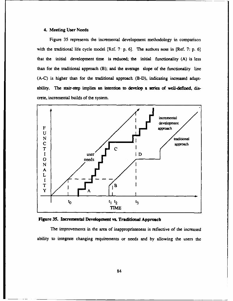
4. Meeting User Needs
Figure 35 represents the incremental development methodology in comparison
with the traditional life cycle model [R,.'f. 7- p. 6]. The authors note in [Ref. 7: p. 6]
that the initial development time is reduced; the initial functionality (A) is less
than for the traditional approach (B); and the average slope of the functionality line
(A-C) is higher than for the traditional approach (B-D), indicating increased adapt-
ability. The stair-step implies an intention to develop a series of well-defined, dis-
crete, incremental builds of the system.
I incremental
development
F I approachUN IraditionalC approachT CI user0 needsNALI -
T BY A
to tl t2 t3
TIME
Figure 35. Incremental Development vs. Traditional Approach
The improvements in the area of inappropriateness is reflective of the increased
ability to integrate changing requirements or needs and by allowing the users the
84
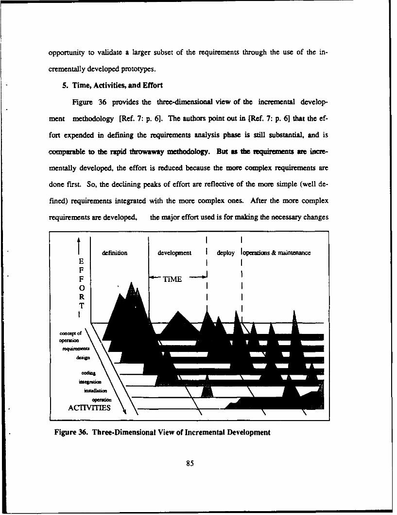
opportunity to validate a larger subset of the requirements through the use of the in-
crementally developed prototypes.
5. Time, Activities, and Effort
Figure 36 provides the three-dimensional view of the incremental develop-
ment methodology [Ref. 7: p. 6]. The authors point out in [Ref. 7: p. 6] that the ef-
fort expended in defining the requirements analysis phase is still substantial, and is
comparable to the rapid throwaway methodology. But as the amquirement are incre-
mentally developed, the effort is reduced because the more complex requirements are
done first. So, the declining peaks of effort are reflective of the more simple (well de-
fined) requirements integrated with the more complex ones. After the more complex
requirements are developed, the major effort used is for making the necessary changes
definition development I deploy Ioperations & maintenanceE I
F TN
RT
ccept ofap~M&n
Figure 36. Three-Dimensional View of Incremental Development
85
! !UMR
or enhancements based on the users validations of the prototypes. Because the com-
plex (not clearly defired) requirements art prototyped up front, there is a significant
amount of effort expended in designing the architecture for the entire system. The in-
cremental, but relative consistency of the coding efforts, as well as the installation
and operations/maintenance activities, are reflective of the improvements in the re-
quirements validation activity of the requirements engineering process.
Ano enhancement that this methdology offers is the ability to validate par-
ticular modules of a system and proceed into the next phase (production coding) while
the other modules of the system are being prototyped and validated. Not all systems
can take advantage of this, given the dynamic nature of the development process, but
in some cases it may apply. This enhancement could be very effective, if applicable, in
meeting delivery deadlines and thus in satisfying user's needs sooner.
6. Implementation Outlook
The incremental development methodology can be partially implemented now.
To fully meet its potential and the goals of the new paradigm, the methodology
is most probably a short-term goal. The integration of reusable software
components into this methodology is essential if wide acceptance is to be gained The
prototyping tools and their associated environment must be built to support this
methodology. Once the environment is in place, the incremental methodology can be
implemented given current technology.
86
D. EVOLUTIONARY PROTOTYPING METHODOLOGY
1. Prototype Development
The evolutionary prototyping methodology develops its prototypes in a similar
fashion as the incremental development methodology. The prototype is incrementally
built, but the simpler requirements are prototyped first, followed by the more complex
ones. The same debate holds here as to which technique is more efficient. Intuitive-
ly, building upon known (simpler) requirements or sengths seems more logical than
tackling the unknown (complex) requirements first. But this is merely intuitive and
there are some logical arguments to support the other technique as well.
The most appealing enhancement that this methodology offers is that the proto-
type serves as the production system. The benefits of not having to build a produc-
tion system from scratch after the prototype is validated should save on many re-
sources (time, cost, maintenance, delivery rates, etc.). The positive side affect of this
is that the users validate the prototype and production system at the same time. The
user, in essence, validates the system as it is being developed and there is no chance
of replication errors as in the rapid throwaway or incremental development methodolo-
gies. The probability of user dissatisfaction should be considerably reduced, and in ar-
eas where the dissatisfaction occurs, the user is not surprised and is aware of the
problem or shortfall prior to delivery. Does this solve the requirements engineering
dilemma? Not necessarily! The software development process is still very dynamic
and requirements may change, even after a particular prototype representation has
been validated by the user. But this methodology seems to allow for the dynamic con-
ditions, more so than the other two methodologies already surveyed. The process of
making enhancements is much more efficient that in the traditional life cycle model.
87
There are some costs associated with the advantages gained through this meth-
odology. "To use the prototype as the production system will require an intensive
prototyping tools environment to support its RAMP (Reliability, Adaptability, Main-
tainability, and Performance)". [Ref. 7: p. 7] The other cost is time. The tirae-con-
suming effort involved in not only constructing the prototype, but simultaneously de-
veloping the design architecture for the operational system places the "rapid" intent in
jeopardy. That is why the prototyping tools environment is so essential to the i xple-
mentation of this methodology.
2. Use of Reusable Software Components
The use of reusable software components in this methodology is not specifically
noted, but just as in the previously surveyed methodologies, their integration into this
methodology appears essential. This is especially important given the complexity of
the development process and the enormous time-consuming factors involved. Since
the prototype will serve as the production system, the use of reusable software com-
ponents makes great sense, especially considering the enhancements and mainte-
nance efforts involved. The use of reusable software components will certainly bring
the time issue closer to meeting the "rapid" intent of the methodology and the goals of
the new paradigm.
3. Evolutionary Prototype Production
The methodology supports the evolutionary process of providing an extxutable
prototype that will serve as the production system. The efficiency of not duplicating
efforts in developing software is moving closer to full automation. Although nct opti-
mally fulfilling the potential of automation, the manual efforts are considerably rduced
and those that still exist in some respects complement the automation process.
88
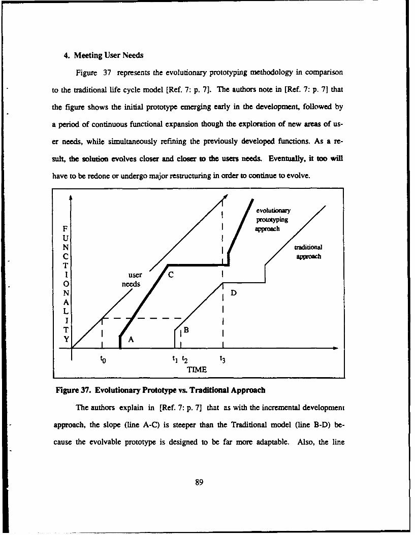
4. Meeting User Needs
Figure 37 represents the evolutionary prototyping methodology in comparison
to the traditional life cycle model [Ref. 7: p. 7]. The authors note in [Ref. 7: p. 7] that
the figure shows the initial prototype emerging early in the development, followed by
a period of continuous functional expansion though the exploration of new areas of us-
er needs, while simultaneously refining the previously developed functions. As a re-
sult, the solution evolves closer and closer to the users needs. Eventually, it too will
have to be redone or undergo major restructuring in order to continue to evolve.
evoluionaryprowotyping
F IapproachU "N traitionalC approachTI user C0 needsN DALIT A
to t1 t2 t3TIME
Figure 37. Evolutionary Prototype vs. Traditional Approach
The authors explain in [Ref. 7: p. 7] that as with the incremental development
approach, the slope (line A-C) is steeper than the Traditional model (line B-D) be-
cause the evolvable prototype is designed to be far more adaptable. Also, the line
89
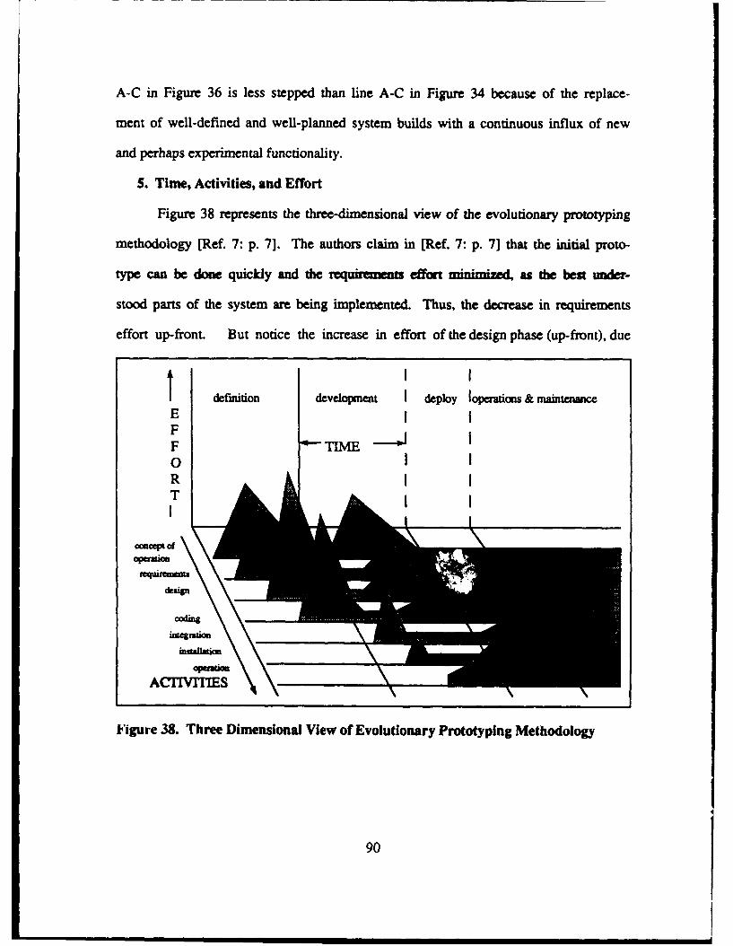
A-C in Figure 36 is less stepped than line A-C in Figure 34 because of the replace-
ment of well-defined and well-planned system builds with a continuous influx of new
and perhaps experimental functionality.
5. Time, Activities, and Effort
Figure 38 represents the three-dimensional view of the evolutionary prototyping
methodology [Ref. 7: p. 7]. The authors claim in [Ref. 7: p. 7] that the initial proto-
type can be done quickly and the .ui ; effort minimized, as the best under-
stood parts of the system are being implemented. Thus, the decrease in requirements
effort up-front. But notice the increase in effort of the design phase (up-front), due
t definition development I deploy leaions & maintenance
E IF
F TIME
09
RT
oo,"Pt of
ACTIVITIES
Figure 38. Three Dimensional View of Evolutionary Prototyping Methodology
90
mainly to the need to architecturally design the operational system. Each succeeding
increment is tackling more difficult problems, but only in small pieces; thus the activity
levels after the initial prototype are relatively constant and overlap significantly.
The increases in effort in the latter phases of the development, though relatively
constant, are worthy of discussion. The extra effort is a result of the enhancements
being made on the initial prototype as changes are made. Since the prototype is being
designed as the production system and the openaonal ovhead that is entailed to
achieve this requires more effort, the overall effort is increased. Also, because the
prototype is also operational, the enhancements will be made on larger and more de-
tailed modules. This is in contrast to the partial sets of requirements that the former
methodologies provided.
6. Implementation Outlook
The future implementation of this methodology is greatly dependent on the de-
velopment of the prototyping tools environment. This dependency on the support sys-
tem will push implerventation out beyond the incremental development methodology's
implementation. Since the need of more intensive prototyping tools delays implemen-
tation, it is more realistically a short-term goal. It is important to note that the delay
in implementation does not contribute to apprehensions toward the implementation of
the new paradigm by the software industry, rather it is contributes to the void exist-
ing in the software prototyping tools environment.
91
E. REUSABLE SOFTWARE COMPONENTS METHODOLOGY
1. Prototype Development
This methodology is strictly an implementation feature rater than an indepen-
dent process. The utilization of reusable software components affects the effort of
and efficiency with which the prototype is constructed. For this reason, reusable soft-
ware components should not be viewed as a "stand-alone" methodology, but should
be integrated into the other methodologies pmrviously surveyed. The utilization of re-
usable software components in both development of prototypes and production sys-
tems (in rapid throwaway and incremental development methodologies) makes the
coding process more efficient and provides a near-term context for introducing a first
generation automatic code generating system.
The development of the prototype using reusable software components does not
enhance the requirements validation process. The users can equally validate proto-
types that are manually coded or coded using reusable software components. But the
effort involved from the designer's or developer's perspective is reduced and the pro-
totype can potentially be developed more quickly.
2. Use of Reusable Software Components
The two main issues involved are how software reliability should be improved
and debugging effort should be reduced for the parts of the system built from reusable
software components. Intuitively, the function of managing the components library
and retrieving functions should coincide with current DBMS (Data Base Management
Systems) technology. The problem is that current DBMS technology is based on re-
lations and is not compatible with the requirements of reusable software compo-
nents. Therefore, the need for a prototyping language that is both specification-based
92
and design-based is necessary to fill the void in current DBMS technology. The de-
velopment of a new language is both complex and time-consuming. The management
of the reusable software components library focuses on organization and storage
space. Both of these solutions to the problems are achievable given current and near-
term technology, but the tasks of constructing, testing, and organizing the compo-
nents will not be something that will be completed in the near-term future.
3. Evolutionary Prtoy Production
The use of reusable software components can produce executable prototypes
that serve as production systems. The major differences are how reusable compo-
nents are used in the methodologies, the level of detail required in developing the pro-
totype, the architectural design requirements, and the constraints that the compo-
nents must meet.
4. Meeting User Needs
Figure 39 represents the reusable software components methodology in compari-
son with the traditional life cycle model [Ref. 7: p. 81. The authors point out in [Ref. 7:
p. 7] that the time required for development is the only parameter which changes,
with the amount of software "reused" determining the significance of decrease.
There is the potential (not shown) for the slope of the functionality curve
(adaptability) to be greater due to the structure and modularity required by the reus-
able software methodology.
The decrease in development time depends on the complexity of the system and
the amount of reusable software components used, and therefore should not be con-
strued to be constant. The reduced development time can be included in each of the
previously surveyed methodologies and should bring the development time closer
93
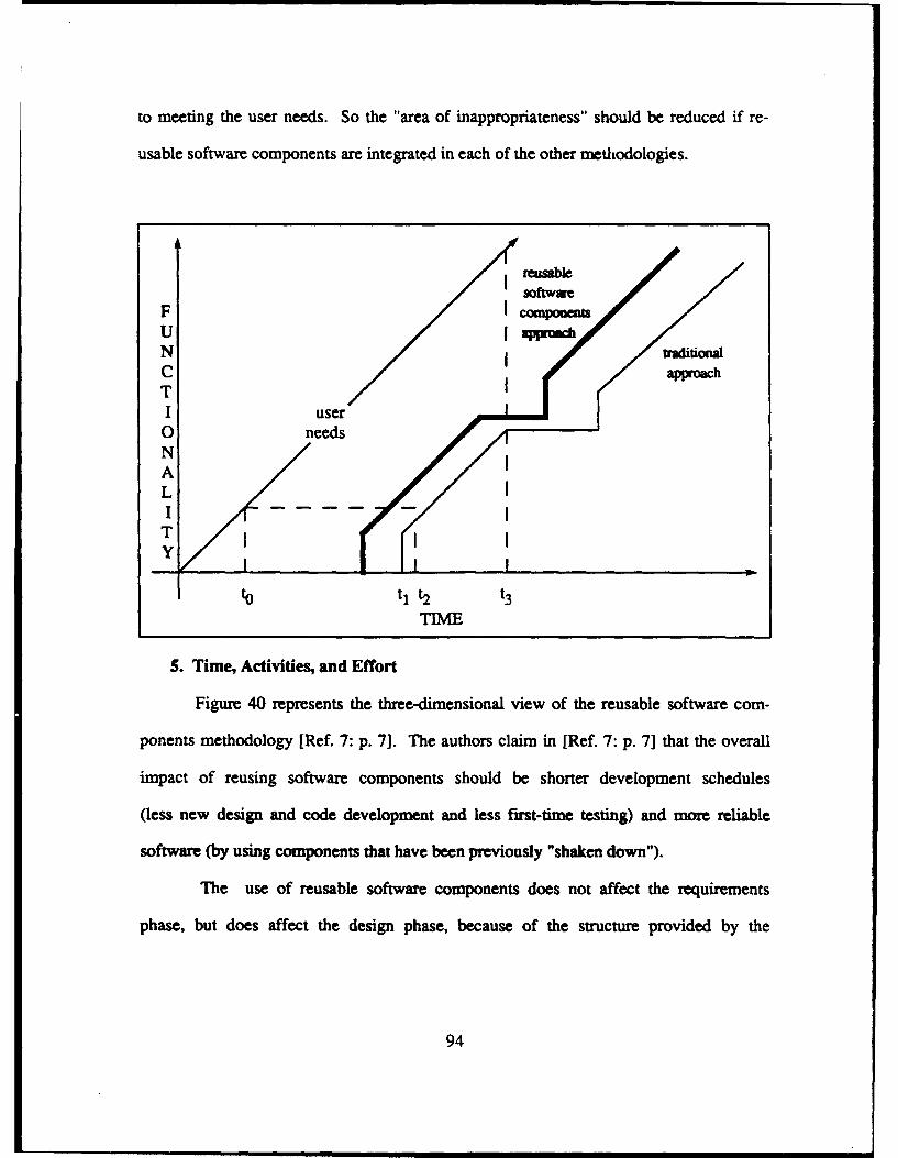
to meeting the user needs. So the "area of inappropriateness" should be reduced if re-
usable software components are integrated in each of the other methodologies.
F necompomU fappamh
NC approachTI user0 needs
NLI T
to tI t2 t
5. Time, Activities, and Effort
Figure 40 represents the three-dimensional view of the reusable software com-
ponents methodology [Ref. 7: p. 7]. The authors claim in [Ref. 7: p. 7] that the overall
impact of reusing software components should be shorter development schedules
(less new design and code development and less first-time testing) and more reliable
software (by using components that have been previously "shaken down").
The use of reusable software components does not affect the requirements
phase, but does affect the design phase, because of the structure provided by the
94
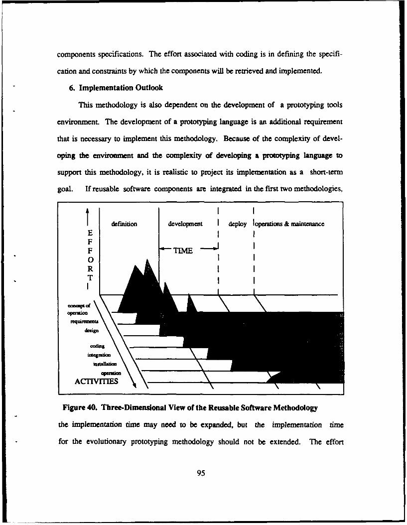
components specifications. The effort associated with coding is in defining the specifi-
cation and constraints by which the components will be retrieved and implemented.
6. Implementation Outlook
This methodology is also dependent on the development of a prototyping tools
environment. The development of a prototyping language is an additional requirement
that is necessary to implement this methodology. Because of the complexity of devel-
oping the envionment and the complexity of developing a prototyping language to
support this methodology, it is realistic to project its implementation as a short-term
goal. If reusable software components are integrated in the first two methodologies,
definition development I deploy loperations & maintenanceE IFF TT E I0RTI
conaceptof
nMquifinlents
Figure 40. Three.Dimensional View of the Reusable Software Methodology
the implementation time may need to be expanded, but the implementation time
for the evolutionary prototyping methodology should not be extended. The effort
95
involved in developing the independent parts of the environment to support the reus-
able software components methodology is comparable in terms of complexity.
F. AUTOMATED SOFTWARE SYNTHESIS METHODOLOGY
1. Prototype Development
The development of the prototype under this methodology is based on automatic
design, coding, and operational system activities, Theoretically, using a VHLL to au-
tomatically generate the prototype and design architecture of the production system is
close to the optimal process of software development. Unfortunately, the technology
is not currently available to implement this methodology and is not expected to be
available any time soon.
2. Use of Reusable Software Components
This methodology uses the reusable component concept to an extent, but relies
more heavily on the VHLL to generate the code and design architecture. The compo-
nents of this methodology will be more skeletal in terms of actual program coding.
More advanced research is required to define the process of how the prototypes will
be coded.
3. Evolutionary Prototype Production
The prototype produced by this methodology will not only be executable,
but will also drastically reduce the requirements validation process because of the au-
tomated synthesis and therefore meet the user's needs more closely than in the pre-
viously surveyed methodologies. The production system would also be more
maintainable, because of the automated synthesis and its ability to make enhance-
ments with very little effort involved.
96
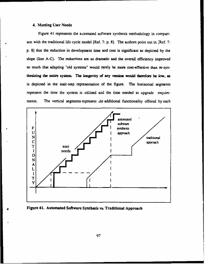
4. Meeting User Needs
Figure 41 represents the automated software synthesis methodology in compari-
son with the traditional life cycle model [Ref. 7: p. 8]. The authors point out in ,Ref. 7:
p. 8] that the reduction in development time and cost is significant as depicted by the
slope (line A-C). The reductions are so dramatic and the overall efficiency improved
so much that adapting "old systems" would rarely be more cost-effective than re-syn-
thesizing the entire system. The longevity of any veaiou would tbrefoe be low, as
is depicted in the stair-step representation of the figure. The horizontal segments
represent the time the system is utilized and the time needed to upgrade require-
ments. The vertical segments represent dhe additional functionality offered by each
automatedsoftware
F synthesisU approach
C approachT userI needs0NA
T ITiY I
* Figure 41. Automated Software Synthesis vs. Traditional Approach
97
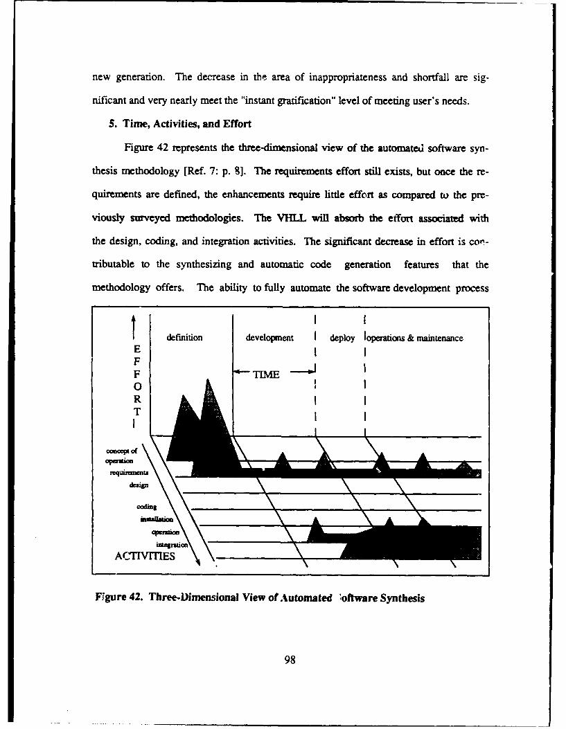
new generation. The decrease in the area of inappropriateness and shortfall are sig-
nificant and very nearly meet the "instant gratification" level of meeting user's needs.
5. Time, Activities, and Effort
Figure 42 represents the three-dimensional view of the automated software syn-
thesis methodology [Ref. 7: p. 8]. The requirements effort still exists, but once the re-
quirements are defined, the enhancements require little effort as compared to the pre-
viously surveyed methodologies. The VHLL will absorb the effort associated with
the design, coding, and integration activities. The significant decrease in effort is cot-
tributable to the synthesizing and automatic code generation features that the
methodology offers. The ability to fully automate the software development process
Tdefinition development I deploy loperations & maintenance
E !FF0RT
oacepiofAA
Feqirem4. eeniesoatiesfAtmtdofwr ytei
ACTIVTES9
Figure 42. Three-Dimensional View of Automated 'oftware Synthesis
98
will enable every user to get exactly what they want and more importantly when they
want it (in almost real-time).
6. Implementation Outlook
This methodology is at least a few rapid prototyping generations away. Neither
the hardware or the software technology are currently available to support its imple-
mentation. The research of this methodology is still in the infancy stages and needs
further developmenL This mthodoloy should definitely be viewed as a long-term
goal. Tlis is not to say that it will not eventually be implemented, but more extensive
research must preclude any realistic attempt at implementation.
9
99
IV. EVALUATION OF PROPOSED RAPID PROTOTYPING MODELS
The evaluation of the published rapid prototyping models is focused more on the
tactical implementation level rather than the strategic approach taken with the meth-
odologies. The models are designed based on either one or a combination of two or
momt of the surveyed methodologies. The evaluation of the models may be viewed as
an extension of the strategic evaluation information of the methodology or sets of
methodologies from which the models are designed. In some cases a particular model
that integrates two or more complementary methodologies may avoid problems that
are caused by one of the methodologies. If this is the case, the features or interaction
of the features that provides the compensation are noted.
The evaluation criteria for the models will be focused on the internal design fea-
tures of each model, the development of the prototype, the support system environ-
ment, and the fulfillment of the tactical goals of the proposed paradigm. The evalua-
tion criteria are 1) formal and explicit o enable automated consistency and complete-
ness checking, 2) prototype development, 3) measurability in terms of cost
estimation, planning, and completeness, 3) use of reusable software components, 4)
maintainability, 5) documentation coding produced, 6) real-time systems, 7) user in-
terface capabilities, and 8) performance issues. Some of the evaluation criteria for the
models could not to be evaluated due to the absence of detailed descriptions. In cas-
es where some vagueness exists, the appropriateness of further research required or
potential implementation shortfalls are noted.
100
A. EVALUATION CRITERIA DESCRIPTIONS
Formal and explicit to enable automated consistency and completeness checking:
This criterion addresses the ability to achieve and demonstrate consistency and com-
pleteness in the specification and design levels in modeling the prototype and the pro-
duction system. Dr. Berzins declares in [Ref. 26: p. 51] that some aspects of the
completeness and consistency of requirements can be checked automatically. Exam-
ples of constraints that can be automatically checked are definition completeness and
type consistency. Type consistency means that the types of the objects involved in
each concept agree with the definition and each use of the concept. Other kinds of au-
tomated checks are also possible, many of which are more difficult to implement. Re-
quirements tracing, control constraints, syntax, and objects are all areas that can be
checked automatically for consistency and completeness. These four areas will be the
focus of the evaluation.
Prototype development : This criterion addresses how efficiently the prototype is
developed. The evaluation of this criteria, with respect to the models, will focus more
on the actual construction of the prototype rather than on the theoretical or conceptual
representation covered in the evaluation of the methodologies.
Measurability in terms of cost estimation, planning, and completeness : The de-
velopment of the prototype should enable a close estimation of cost of developing the
production system for budgeting considerations. The prototype should entail the level
of planning required to produce the production system. The prototype should give a
reasonable representation of completeness in terms of requirements implementation
and real-time effectiveness.
101
Use of reusable software components - This criterion addresses how the reusable
software components are retrieved, used, and the complexity and efficiency in-
volved.
Maintaiability : This criterion addresses how well the model allows for evolu-
tionary changes and whether or not the maintenance effort is improved by the design
and implementation of the model.
c c ding produced : This criterion addresses whether documenta-
tion is automatically or manually produced to supplement the coding. This documenta-
tion of concern is primarily that produced when reusable software components are
linked. However, it is also important to consider the quality of the documentation for
the entire development process.
Real-time systems : This criterion addresses whether the model handles real-time
constraints or does it leave the real-time issues to the underlying system.
User interface capabilities : This criterion addresses whether the model permits
the use of the user interface features currently available or software developed with-
out the aid of any tools. It also addresses whether graphics features are included to
facilitate dataflow or documentation requirements as the software is being developed.
Performance issues : This criterion addresses how well the model performs in pro-
ducing large real-time systems, both conceptually and realistically (if currently being
implemented). This criterion also addresses real-time effects, prototype develop-
ment time, enhancements, and meeting delivery schedules.
102
B. CAPS (COMPUTER AIDED PROTOTYPING SYSTEM) RAPID
PROTOTYPING MODEL
1. Formal and Explicit to Enable Automated Consistency and Completeness
Checking
CAPS has only limited automated consistency and completeness checking. The
only automated process for checking for consistency is facilitated by the syntax-di-
rected editor. The syntax-directed editor, a compoent tool of the designer intrface,
helps speed up the reusable software component retrieval and linking processes by
eliminating syntax errors, automatically supplying keywords, and prompting the de-
signer with a choice of legal syntactic alternatives at each point [Ref. 8: p. 26]. The
syntax-directed editor, in support of PSDL, handles all the context information er-
rors. The process of correcting syntactical errors is not fully automated and requires
some interaction between the system and designer to resolve errors. So the automa-
tion of this process is consistent with meeting real-time constraints, but is limited to
only the context information errors.
The model does not provide any automated requirements tracing for consistency
or completeness. This is also attributable to the inability to perform automatic theo-
rem proving. The task of checking for completeness and consistency is left solely to
the designer. The manual process of requirements tracing is enhanced by the devel-
opment of the process, but still is subject to errors or oversights in the requirements
engineering process.
The model does address consistency and completeness checking, as much as
current technology allows. The ability to check for context-free inconsistencies and
errors can be integrated into the model either during model development, if the
103
technology becomes more advanced, or as a future feature after the model is initially
implemented.
2. Prototype Development
The CAPS prototype is developed incrementally and is intended to be evolution-
ary. The design-based PSDL language is used to retrieve, provide instantiaion with
regard to control constraints, and link reusable software components. The linking of
the components results in an executable prototype tha represents the user and sys-
tem requirements.
The use of reusable software components is an efficient means of producing the
code for the prototype. Conceptually, the process of retrieving the components is effi-
cient and will result in rapid development of the prototype. The efficiency of the proto-
type development is based on two important factors. The first is on the ability of the
designer to decompose the specifications to match the components in the software li-
brary. The quality of the decomposition of the specification wil affect the develop-
ment of the prototype. Designers experienced in the prototyping process will eventu-
ally provide specific specifications, but the initial systems will probably suffer from
the attempts of novices. The other factor is the completeness of the software library.
The effort and time expended on manually coding components that are not in the soft-
ware base will also affect the development process. This problem will also improve
as the learning curve of designers improves.
3. Measurability in Terms of Cost Estimation, Planning, and Completeness
Because the model is evolutionary, the cost of developing the prototype closely
reflects the total cost of the production system. Even though there may be some cas-
es where the prototype developed by retrieving reusable software components will
104
requires manual enhancing to meet production system needs, the costs will still be
close. This is important in terms of defining the upper bounds of what requirements
can actually be implemented given the users resource constraints.
The planning effort to develop the prototype approximates the total planning
effort of the production system. . Once the prototype is validated by the users, little-
additional planning will be required to transform the prototype into the production
The measurability of completeness is relatively guaranteed by the evolutionary
design of the prototype. Completeness cannot be absolutely guarenteed because
there will be cases where the validated prototype needs detailed enhancements to
satisfy the production system requirements. Even so, the level of completeness that
the designer can represent to the user through the prototype is very important in
terms of validation.
4. Use of Reusable Software Components
Since CAPS is evolutionary, the reusable software components in the prototype
also serve as the coding for the production system. The process of retrieving the com-
ponents only once is more efficient than having to retrieve components for the proto-
type and then again for the production system.
The development of the component software base is very complex and is con-
ceptually designed to be object-oriented. The structure of the software base is not
completely described and is still being researched. Given the recent success of ob-
ject-oriented software products, the structure of the software base should be defined
more clearly in the near-term future.
105
5. Maintainability
CAPS has some maintenance features that improve upon current software devel-
opment procedures. The evolutionary changes in the maintenance phase are more
rapidly constructed because of the use of reusable software components and the pro-
totype development process. But the CAPS model does not handle the maintenance
effort automatically. If enhancements need to be made to a component, any interfac-
ing between linked components and the changed component is unaffected by the
change. The components need to be re-linked to support the changes. If ma-
jor maintenance changes are required, then the prototyping process may need to be
re-initiated. This is obviously not an optimal solution to the maintenance problem,
but is reflective of the current technology.
6. Documentation Coding Produced
CAPS requires a specification part for each component and the PSDL implemen-
tation part for the composite components documents the linking process between
components. Also, the paraphraser component provides English explanations. Main-
tenance is done at the PSDL level. The maintenance phase does not have to "look"
at automatically produced code, so documentation is irrelevant.
7. Real-Time Systems
CAPS provides special features particularly appropriate for real-time systems.
PSDL and the execution support system provide these features.
Dr. Luqi explains in [Ref. 8: p.27] that the PSDL executable prototype is used
to check real-time requirements because the cildcal timing constraints and the most
important concerns, e.g. maximum execution time, minimum response time, and syn-
chronization are very hard to validate without actually constructing a valid schedule
106
and observing the execution of the prototype. Most real-time systems are used to
monitor and control physical processes external to the computer in the embedded sys-
tem. The precision and accuracy requirements in the design of a real-time control
system complicate the demands on the execution of the designed software system.
For these reasons, the design of real-time systems imposes a different set of de-
mands. The formal structure in PSDL specifying real-time constraints provides a ba-
sis for automating the production of code from the formal requiren ts specifications
to the underlying programming language. The execution of PSDL prototypes helps to
verify that the design of an embedded system with given timing constraints for the
components in the prototype will interact with its environment in a way that meets
the timing constraints of the system as a whole.
By accentuating the real-time constraints in the design process, the task of in-
suring that the prototype reflects the constraints must be handled by the tools within
the prototyping system. These tools are components of the execution support sys-
tem. They are the static scheduler and the dynamic scheduler. Dr. Luqi points out in
[Ref. 8: p. 1] that the purpose of the static scheduler is to schedule times for the com-
putations with hard real-time constraints in such a way that all the timing constraints
will be guaranteed to be met. Time slots are statically allocated for the worst-case
execution times of the operators. The abstract treatment of the timing information is
an important property of the data flow since only the essential time ordering affecting
the events in the computation are given. These time orderings act as constraints on
the static scheduler, and allow the flexible exploration of schedules for multi-proces-
sor configurations. The purpose of the dynamic scheduler is to utilize time slots not
107
needed for the time critical computations to schedule the computations that do not
have hard real-time constraints.
Portions of PSDL, the static scheduler and the dynamic scheduler have been im-
plemented [Ref. 27]. These tools are theoretically sound, but full implementation of
the tools may expose some unforeseen problems.
8. User Interface Capabilities
CAPS features some user interface features that will facilitate the prottype de-
velopment. Dr. Luqi claims in [Ref. 8: p. 27] that the graphics tool, which is part of
the syntax-directed editor, provides a graphical view of the dataflow diagram part of
the PSDL implementation of a component module. The graphics tool helps the design-
er visualize the relationships between the compenents of a decomposition by means
of a two-dimensional dataflow diagram, and provides a convenient way to enter and
update the decomposition information in the enhanced dataflow diagram, which is part
of a PSDL implementation of a component.
This graphical representation of dataflow will make it easier for designers to
evaluate the effect of the prototype development. It is much easier to visualize
and understand a graphical representation than to interpret hard text descriptions of
the same process.
9. Performance Issues
CAPS has some significant performance features. Conceptually, given current
technology, it provides the tools and design to produce a prototype that is executable
and evolutionary. Once the model is implemented and designers become experienced
with PSDL and the development process, the performance resulting from this model
will be much greater than current methods of software development. Although there
108
is considerable automation in this model, there remains a significant human
interaction effort. This increase in automation may be integrated into the initial imple-
mentation as technology and research efforts allow.
The performance feature that is most attractive is the ability to handle real-time
constraints. The handling of real-time constraints allows the prototype and produc-
tion system software to execute in a hard real-time environment. The added automa-
tion discussed earlier only enhances the development process and not necessarily the
execution of the software.
C. IPS (INTEGRATED PROTOTYPING SYSTEM) SOFTWARE PROCESS
MODEL
1. Formal and Explicit to Enable Automated Consistency and Completeness
Checking
The IPS Software Process Model [Ref. 20] also provides for only limited con-
sistency and completeness checking. The model features a syntax-directed editor
which corrects only context information. Errors in context-free information are left to
manual means, just as in CAPS.
The only other consistency and completeness checking that is performed is
done through an interactive process between the user, designer, and the DAA
(Design Activity Agent) [Ref. 20]. The graphical representations are produced by
the internal tools within DAA. DAA provides the graphical representation of the hi-
erarchical design of the system and then the designer and users review the structure
of the designed system. The errors or misrepresentations have to be manually de-
tected and changed because ART (Automated Reasoning Tool) [Ref. 201 is not de-
signed to check for context-free defects.
109
2. Prototype Development
There are two different prototypes produced in the IPS Software Process Mod-
el. The design prototype is developed within the DAA environment. The design pro-
totype is the focal point of the model and is intended to be the prototype that will sat-
isfy a majority of the validation requirements. The other prototype is an executable
prototype that is transformed from the design level code into high level programming
code by an automatic program generator.
The design prototype is constructed efficiently, using reusable DODAN compo-
nents from the ART knowledge base. The hierarchical structure of the design compo-
nents after linking is easy to represent graphically and thus easier to review in the
validation process. Since the design components are much smaller in comparison to
programming language coded components, and have a hierarchical structure, enhance-
ments or modifications to the design structure are easier to execute.
The deveiopment of the executable prototype is not clearly defined. The execut-
able prototype will somehow be developed by transforming the design level code into
a high level programming language. Whether the prototype will be constructed of re-
usable software components or not is undefined at this point. But the use of a reus-
able design component implies that reusable software components will be used in
some manner.
3. Measurability in Terms of Cost Estimation, Planning, and Completeness
The IPS model, as currently defined, only provides limited cost estimation of the
overall production system. Since the development process of the executable proto-
type is not clearly defined, it is unclear what the relationship is between the cost of
110
developing the design prototype, the cost of developing the executable prototype, and
the cost of the overall production system.
The planning effort expended in the design phase should account for the measur-
ability of planning for the remaining efforts in the development of the production
system. This is the intent of the model. If sufficient planning efforts are expended in
the requirements, specifications, and design phases, then the automatic program gen-
erator should be able to transform those coded efforts into high level programming lan-
guage code. This claim is conceptually valid, but only if the automatic code generator
is fully automated.
The completeness of the production system should also be primarily abs -rbed in
the first three stages. The optimal design prototype, along with the automatic pro-
gram generator should conceptually secure completeness. This is dependent partially
on the automatic program generator, but probably more on the ability of designers and
users to insure completeness in the design phase.
4. Use of Reusable Software Components
Yin and Tanik describe in [Ref. 25: p. 3] that the use of DODAN components
from the ART knowledge base implies the intended use of reusable software compo-
nents in the development of the prototype, and therefore in the production system.
The structure of the ART knowledge base, which contains the design components, is
object-oriented. The schema in the knowledge base represents an object or class of
objects, its associated attributes, and its membership in other classes . The structure
of this knowledge base supports modularity. This modularity should facilitate the re-
trieval process.
1l1
The design of a software component base for the high level language is not de-
fined, but the same basic conceptual design as the ART knowledge base seems logi-
cal. The additional features such as inheritance relations and interfacing rules should
be included in the reusable software base to facilitate maintenance as well as consis-
tency and completeness checking efforts.
5. Maintainability
Conceptually, one of the most attractive features of the model is its ability to
handle maintenance very efficiently. If modifications or enhancements are necessary,
then the designer need only go back to the design phase, make the modifications, and
then let the automatic program generator complete the coding efforts. Since the de-
signer never has to go iito the system produced coding, the maintenance effort is sig-
nificantly reduced. The ART knowledge base management system effectively sup-
ports the maintenance process in the design phase of the development.
6. Documentation Coding Produced
The IPS Software Process Model does not produce any additional documenta-
tion other than that which is included in the componenms in the knowledge base. Th-s
would pose a problem if maintenance was dependent on modifying system-produced
coding. But the maintenance effort does not require this dependency and the authors
of the model contend that the automatic program generator will never require interpre-
tation of the system-produced cde. If this authors' contention is correct, then the
lack of documentation will not pose a problem. But if the authors' contention is not
correct, then the lack of documentation could be disastrous in terms of efficiency.
112
7. Real-Time Systems
Yin and Tanik explain in [Ref. 25: p. 11] that the IPS Software Process Model,
as currently defined, does not insure that real-time constraints are met. The control
and timing constraints are not addressed, but may be included in the post-design
phase descriptions. The timed event-flow feature depicted in Figure 20 does not
handle timing constraints as the name implies. It is used merely to generate the sys-
tem state transition diagram.
The lack of attention to real-time constraints is a significant oversight. This hin-
ders the model's ability to be recognized as a viable software development model,
given the user's growing requirements and software applications.
8. User Interface Capabilities
The conceptually-defined user interface features of DAA are currently
dependent on ART. Since the model is dependent on the existing user interface fea-
tures of ART, it also inherits the existing limitations. As an example, the authors in
[Ref. 20: p. 8] note that the ART graphics networks are implemented by using inherit-
ance relations, and has the tree-like structure with one root node. This feature limits
the capability of DAA dependency analysis, since a software design may have a data-
flow or control flow with a non-tree structure.
Although the existing user interface features are not optimal, they are sufficient
to introduce the initial implementation of the model. The conceptual description of the
designed user interface features is explicit and well defined. But the implementation
of the designed user interface is critical to fulfill the goals of the model.
113
9. Performance Issues
The evaluation of performance in this model is hampered by its partial design de-
scription. The conceptual design of the model up to the design phase is comparable
with other models, but the post-design phase description is so vague and strategical-
ly presented that performance of the production system cannot realistically be
evaluated. It is the strategic description that not only raises questions about
performance, but also about the probability of realistically implementing this model in
the near to short-term future.
The emphasis on the design phase should enhance the software development
process. Since automatic code generation is one of the goals of the new paradigm, the
effort has to be expended to validate the design level interpretation of the require-
ments specification. The research effort that has produced DAA apd the design level
process description is commendable. If the remainder of the model can be defined and
implemented to the detailed level of DAA, then the IPS model could gain wide accep-
tance within the computer science community.
D. GENERIC (SYSTEMS DEVELOPMENT AND MAINTENANCE
ENVIRONMENT) MODEL
1. Formal and Explicit to Enable Automated Consistency and Completeness
Checking
The Generic (SDME) Model [Ref. 21] is not defined in enough detail to
determine if it performs automated consistency and completeness checking.
114
2. Prototype Development
The Generic (SDME) Model is designed under the rapid throwaway methodolo-
gy. The prototype developed under this model is used primarily to facilitate require-
ments validation. The model then calls for the production system to be constructed in
a step-wise refinement similar to the traditional life cycle model. The reasoning be-
hind this effort is that a production system that is constructed with the prototype as
the skeleton for the software is too general. The specifics that can be produced by the
traditional life cycle model are intended to be preserved by using the Generic
(SDME) Model.
The model lacks a specific description of how the prototype is to be constructed.
The use of reusable software components is not mentioned. It is implied that the
prototype will be constructed rapidly and will only represent a reduced set of require-
ments deemed most important by the users and designers. Therefore, the implied
use of reusable software components may provide more detail than that intended in
the model.
The intent for the construction of the prototype is clearly described, but the rea-
soning is not valid. The generalization concerns described in Chapter II are a reflec-
tion of the skepticism of the new paradigm. Granted that the use of the same reus-
able software components will result in generalization to a certain extent, the design-
er is free to provide any control constraints or detailed enhancements as required.
The prototype is not required, given the user and system requirements, to produce all
the specific details of the production system necessarily. They only have to represent
the most important requirements. The prototype could be as specific as the designer
115
wants, although the speed of the prototype development and the intent of the para-
digm could be compromised.
The partial set of requirements represents only the periphery of the intended sys-
tem. The validation process assists in identifying some of the misinterpretations or
undefined requirements, but will not represent the interfacing between the prototypes
of the requirements. The validated requirements then must be regenerated, a process
which is susceptible to misrepresentation or changes to the previously validated re-
quirements. This duplication of effort is not very efficient and does not address the
problem of the dynamic state of software development. The cited shortfalls of this
model prevent the model from making a great impact on the software development
process. The increased effort of developing the prototype does not offset the produc-
tion benefits in the overall system.
3. Measurability in Terms of Cost Estimation, Planning, and Completeness
The cost associated with developing the prototype in the Generic (SDME) Mod-
el does not reflect an estimation of the costs of the overall system. The partial repre-
sentation of requirements in the prototype and the duplication of effort to develop the
production system is so diverse that even increasing the cost by a constant factor
would be unreliable.
The planning effort of developing the prototype is also not reflective of the plan-
ning effort of the overall system. The planning effort of the prototyping phase is fo-
cused on defining the requirements and representing them in the prototype. The issue
of design architecture is not addressed until the requirements are validated in the pro-
totyping phase. The planning involved in designing the production system is
116
dependent on the requirements and the underlying system, and cannot be estimated
based on the planning done in the prototyping phase.
The completeness of the prototype is dependent on the needs of the users and
the complexity of the proposed system. The definition of the model reflects the inabili-
ty, in the author's eyes, .o produce completeness in the prototyping phase. There-
fore, it is not feasible to expect that the prototype developed under this model will
provide any reliable estimation of the completeness of the overall production system.
4. Use of Reusable Software Components
The Generic (SDME) Model is not defined in enough detail to determine if the
use of reusable software components is intended in the development of the proto-
type. The model certainly could benefit from the integration of reusable software com-
ponents, primarily to reduce the amount of time in developing the prototype.
The amount of detail provided may be more than required, but the rapid production of
the prototype by using reusable software components would outweigh the detail is-
sue.
5. Maintainability
The Generic (SDME) Model, as currently described, will not support mainte-
nance well. The model will suffer from the same problems and shortfalls that exist in
the traditional life cycle model. The maintenance or evolution of the system following
implementation will require reverting to the internal stages of the model and starting
over each time maintenance is required. This is very inefficient and contradicts the in-
tent of the new paradigm.
117
6. Documentation Coding Produced
Documentation coding produced in the Generic (SDME) Model is totally manual
and is dependent on the programmer for the amount of detailed documentation pro-
duced. There is no clear definition of any documentation efforts involved in the proto-
type development process described in the model.
7. Real-Time Systems
The Generic (SDME) Model is not defined in enough detail to determine if the
prototype or production system will function as a real-time system. It is doubtful that
it will, as currently defined, due to the lack of a prototyping language or tools to
support real-time constraints. Any efforts to insure real-time constraints will have to
be absorbed into existing programming languages and operating systems.
8. User Interface Capabilities
The Generic (SDME) Model does not define any tools that would provide user
interface features that would support the prototyping process.
9. Performance Issues
The prototype development process or construction of the production system in
the Generic (SDME) Model will not produce any performance increases. The lack of
support system tools and automated processes prevent this model from producing
better systems. The only enhancement would be that a subset of the requirements
would be validated earlier in the software development process by using the rapid
throwaway prototype. But this effort only enhances the software development pro-
cess and does not address the software performance issue at all.
118
V. THE NEW PARADIGM'S RELATION TO DoD SOFTWARE
ENGINEERING REQUIREMENTS
DoD has long been a dominant agency affecting the development of software engi-
neering. The research funded by DoD has contributed greatly to the current state of
current computer technology. The rapid prototyping paradigm is also being supported
by DoD, primarily through research funding and the sponsorship of conferences and
workshops.
There are many issues that are related to DoD's involvement in supporting the in-
troduction of the new rapid prototyping paradigm. This chapter will address some of
these issues, such as DoD's commitment to Ada as its standard programming lan-
guage and how the current policies and regulations are to be modified to complement
the new paradigm. Also, recommendations on overall strategic goals and decom-
posed near-term, short-term, and long-term goals are provided to facilitate DoD's
implementation of the new paradigm to support future software needs and require-
ments.
A. COMMITMENT TO ADA AS DoD'S STANDARD PROGRAMMING
LANGUAGE
DoD's strong commitment to Ada has produced some significant issues in the
software industry. One of the issues is that DoD introduced Ada and placed the con-
straint on software contractors that all new software projects designed for DoD be
coded in Ada programming language. This constraint, though not warmly received by
119
the software industry, has been a factor in the standardization of software products in
use by DoD. This standardization has reduced the requirement to support many dif-
ferent programming languages and the required underlying systems to support them.
The fact that all new software must be written in Ada has placed some more con-
straints on how the software is developed mechanically, but the effects on the tradi-
tional life cycle model has been minimal.
When DoD placed the constraint of having all software implemented in Ada code,
the software industry initially balked. The financial impact of developing software by
the industry was only minimally changed, but the financial impact of the maintenance
efforts were greatly affected. The reduction in DoD costs of supporting multiple un-
derlying systems to support the myriad of programming languages also affected the
software industry. DoD has a growing need for large real-time systems to support
its technologically advanced weapons systems and world wide communications re-
quirements. There is no single agency in the nation that has the software needs and
financial support to compete with DoD as a software consumer. Therefore, when the
software industry was required to produce all code in Ada, they complied to secure
and maintain the relationship with DoD. If the software industry in the United States
would have refused to abide by this constraint, and DoD went outside of the Unit-
ed States to fulfill its software requirements, the industry would have suffered
financially. This influence over the software industry has proven beneficial to not only
DoD, but the software engineering field as well.
If DoD exercises the same influence and requires that the rapid prototyping para-
digm be instituted as a replacement to the traditional life cycle model, it is reasonable
to assume, based on the Ada experience, that the software industry would adopt the
120
rapid prototyping paradigm. Considering the decreasing defense budget and the in-
creasing software costs, it is important that DoD adopt the paradigm and influence
the course of the software industry.
The other significant issue that DoD's commitment to Ada provides is the efficien-
cy gained by the embedded language. The use of pre-designed packages can be
viewed as a precursor to the use of reusable software components in the new para-
digm. The instantiation efforts and linking efforts are conceptually similar. This simi-
larity and the successes experienced provide the necessary foundation to support an
aggressive effort by the software industry to implement the new paradigm. Although
Ada cannot be used in its current state as a prototyping language, the developmental
lessons learned in the process of introducing Ada should ease the process of con-
structing a prototyping language to support future implementation.
B. CHANGING TECHNOLOGY REQUIRES POLICY UPDATES
Traditionally, with respect to software, DoD has not had a very good record of
changing policies and procedures to keep up with advancing technology. Even the im-
plementation of Ada took a significant amount of time. The process of implementing
the traditional life cycle model is a good example of how complicated and lengthy the
policy changing process is.
The Waterfall model was introduced in 1970, but was not established as the DoD
standard until 1983. While DoD was testing and evaluating the use of the Waterfall
Model during this period, development of software in general continued to be in a
state of disaster. Even though DoD knew that they needed a software development
model, the bureaucratic requirements of exhaustive testing and evaluation prolonged
121
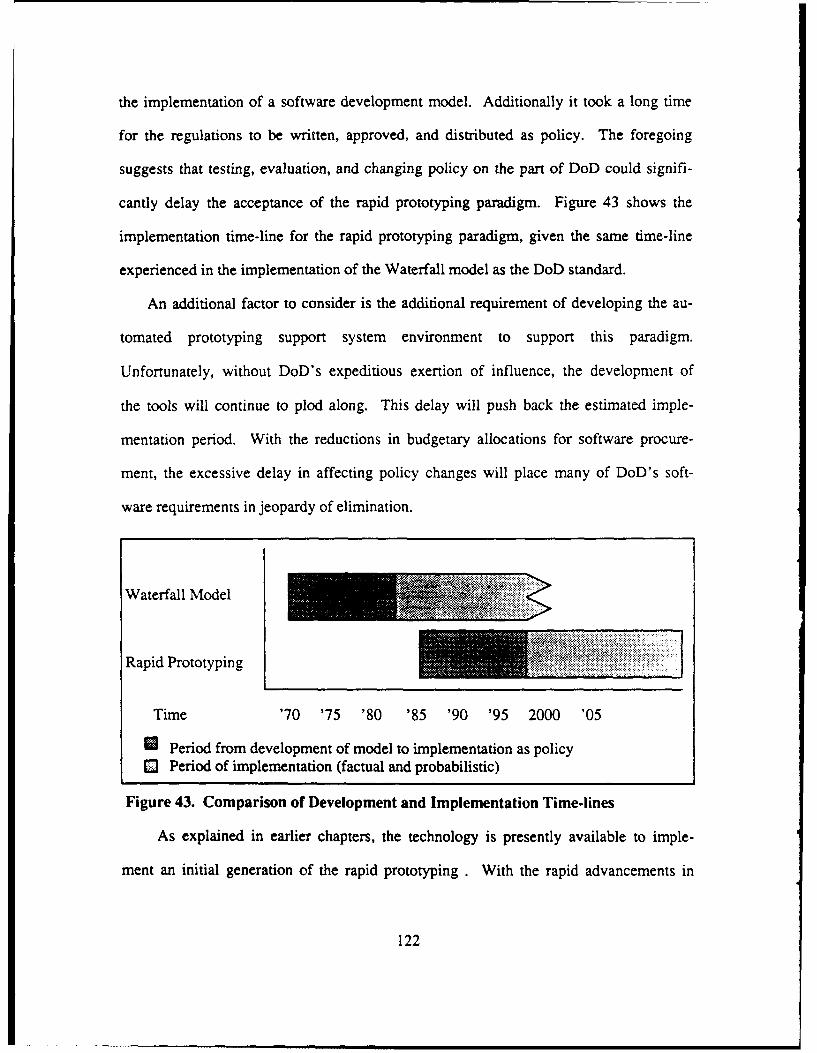
the implementation of a software development model. Additionally it took a long time
for the regulations to be written, approved, and distributed as policy. The foregoing
suggests that testing, evaluation, and changing policy on the part of DoD could signifi-
cantly delay the acceptance of the rapid prototyping paradigm. Figure 43 shows the
implementation time-line for the rapid prototyping paradigm, given the same time-line
experienced in the implementation of the Waterfall model as the DoD standard.
An additional factor to consider is the additional requirement of developing the au-
tomated prototyping support system environment to support this paradigm.
Unfortunately, without DoD's expeditious exertion of influence, the development of
the tools will continue to plod along. This delay will push back the estimated imple-
mentation period. With the reductions in budgetary allocations for software procure-
ment, the excessive delay in affecting policy changes will place many of DoD's soft-
ware requirements in jeopardy of elimination.
Waterfall Model
Rapid Prototyping .jjjjjj
Time '70 '75 '80 '85 '90 '95 2000 '05
* Period from development of model to implementation as policyO Period of implementation (factual and probabilistic)
Figure 43. Comparison of Development and Implementation Time-lines
As explained in earlier chapters, the technology is presently available to imple-
ment an initial generation of the rapid prototyping . With the rapid advancements in
122
technology, future generations could be implemented before the implementation esti-
mate depicted in Figure 45. But to take advantage of the full range of benefits of the
new paradigm, the process of changing policies need to begin much sooner than was
experienced in the implementation of the traditional life cycle model. The policy
changes should be progressively modified to correspond to the advances in develop-
ing the new paradigm. This would allow the available rapid prototyping features to be
utilized, thus making improvements on the current state of software development.
C. STRATEGIC GOALS FOR DoD'S IMPLEMENTATION OF NEW
PARADIGM
DoD should establish strategic goals for the overall implementation of the rapid
prototyping paradigm. These strategic goals should encompass the planning require-
ments prior to initial implementation and future enhancements of the paradigm. The
strategic goals will be decomposed into near-term, short-term, and long-term goals
in the following sections, which will explain in more detail how the paradigm should
be implemented. These strategic goals provide the most critical actions that must be
taken to insure implementation.
DoD must exert its authority now
DoD has to take the position that it intends to procure only software that is
developed under the rapid prototyping paradigm. The intent of taking a strong posi-
tion will result in an increase in effort by the software industry to develop the
necessary support system. The stages should be developed to reflect its strong com-
mitment to rapid prototyping.
123
DoD must establish intermediate Time-lines
Within the implementation stages described above, DoD must establish in-
termediate stages for meeting the proposed implementation period. These intermedi-
ate stages must include stages to produce completed conceptual rapid prototyping
models, a prototype of the prototype support system, and a completed prototype sup-
port system environment. There could also be more intermediate stages to define the
internal development of the prototyping support system environment. The process of
selecting a model or a set of models could be commensurate with existing procure-
ment procedures which include competitive contractual bidding.
Make policy changes incrementally
The policy changes should be made incrementally to keep up with the rapid
prototyping features as they are developed, tested, and implemented. These incre-
mental policy changes would serve several purposes and would decrease the overall
implementation time. The incremental changes would force the software industry to
transition to the new processes of software development and would provide the en-
hancements to the requirements validation process initially without waiting for the
entire system to be completed. Another reason to change the policies incrementally
is that the process of producing the formal regulations upon implementation will be re-
duced considerably. Rather than waiting until the end to begin production of the for-
mal regulations, the major components of the regulations will already be completed
and would only require integration into the final formal regulations.
Continue funding research for future generations of rapid prototyping
Rapid prototyping will continue to evolve as advances in technology are
made. Current technology limits which methodologies that can be modeled and
124
implemented. Even though it is recommended that DoD establish stages for the ini-
tial implementation of rapid prototyping, it should not be construed that the commit-
ment should stop at that initial implementation. The eventual modeling and imple-
mentation of such methodologies as the automated software synthesis methodology
is just as important as the initial implementation of the rapid throwaway methodolo-
gy. Therefore DoD needs to continue funding research efforts which would eventually
produce the implementation of such an advanced rapid prototyping methodology.
These strategies are evolutionary. With advances in computer technology
and continued research efforts, the strategies could easily apply to future generations
of the rapid prototyping paradigm. The strategies could also be improved upon as re-
quired to make the implementation of the initial or future generations more efficient.
D. NEAR-TERM GOALS FOR DoD'S IMPLEMENTATION OF NEW
PARADIGM
The near-term goals described below are all currently feasible, given current
technology. The near-term goals should be able to be implemented within a five to
seven year period.
Implement a rapid throwaway prototyping model
A model designed on the rapid throwaway methodology, such as the generic
(SDME) model is capable of being implemented now. This goal should be viewed as
very near-term, within a two year period. The lack of need for a prototyping support
system would allow this rapid implementation. The implementation of this type of
model would provide some instant enhancements to the current software develop-
ment process, particularly in the requirements validation process. The greatest
125
impact would be the ease of transition from current software development processes,
in contrast to jumping right into an evolutionary prototyping model.
Develop and implement an incremental prototyping model
The development of an incremental model is more complex and would require
more time. It is conceivable that an incremental prototyping model could be devel-
oped and implemented near the outer bound of the goal period (eight to ten years).
The experience gained from exposure to the rapid throwaway prototyping model
should make the transition into the more detailed model easier. The environment to
support an incremental prototyping model could be developed within this period of
time since it is not very complex and is achievable now, given current technology.
Initiate prototyping tools testing and evaluation
There are sufficient prototypes of tools being developed currently to allow for
initial testing and evaluation. This process needs to be formally defined and docu-
mented to insure that the tools will support both near-term and short-term goals.
The process of testing and evaluating the prototyping tools will not be completed in
the near-term, but the process should be initiated if short-term goals are to be me"
Develop a prototyping language
The prototyping language, which is necessary to support the evolutionary and
reusable software components methodologies needs to be developed during thiS goal
period in order to meet short-term goals. The prototyping language needs to be both
specification-based and design-based to facilitate both the evolutionary and reusable
software components methodologies. It is conceivable that the development of the
language and the initial stages of testing and evaluation could be completed in the
near-term.
126
Build reusable software component library
The construction of the reusable software component library, will require a sig-
nificant effort and will consume many years to complete. The design of the library
structure needs to be defined in the very near-term and the process of developing the
components needs to start soon thereafter. DoD should place a constraint on the li-
brary design that it must be object-oriented and support efficient retrieval and man-
agement procedures. The major constraints on the construction of the components
should be that they be written in Ada and that they support instantiation of control
constraints . It is also essential that every component in the library have an associat-
ed formal specification and a measure of how thoroughly it has been tested or whether
it has been proven correct. Without this information, designers cannot tell what the
components can do or whether they are sufficiently reliable.
Monitor prototyping/CASE tools development
DoD must insure that the development of the prototyping tools is consistent
with future goals . The persistent push to the edges of technology will ensure that fu-
ture generations of the paradigm are implemented. This monitoring process includes
not only new tools that are being developed, but also the enhancements to existing
tools deemed necessary during the initial tools testing and evaluation process de-
scribed earlier. This process is very important for enabling future implementations of
rapid prototyping methodology-based models.
127
E. SHORT-TERM GOALS FOR DoD'S IMPLEMENTATION OF NEW
PARADIGM
The short-term goals require either more intensive development process efforts
or advances in technology which exceed the near-term bounds. The short-term goals
should be implemented within a fifteen to eighteen year period.
Evaluate incremental prototyping model
Prior to implementation of a more advanced rapid prototyping model, an eval-
uation of an already implemented model needs to be conducted. This evaluation pro-
cess is important, since there may be some design flaws that require correction in the
design of new models. If known or existing defects are not corrected early in the evo-
lutionary process of introducing more advanced rapid prototyping models, any
potential enhancements will be lost through the existing defects. DoD must ensure
that the evaluation of implemented models is conducted and that efficiency is opti-
mized given existing technological constraints.
Develop and implement evolutionary prototyping model with reuse capabilities
The development and implementation of an evolutionary prototyping model
should be the focus of attention in the short-term period. The evolutionary prototyp-
ing model, such as CAPS or IPS, needs to include the utilization of reusable software
components. The need for the software industry to automate the coding process is
critical, given the growing budgetary constraints. DoD must push the software indus-
try to produce an evolutionary system that enhances both the requirements engineer-
ing and coding processes.
The evolutionary prototyping model is very important for the improvement of
the maintenance process in future software development projects. Since the
128
maintenance costs represent the majority of overall costs, DoD must ensure that a
rapid prototyping model that decreases maintenance costs is implemented as soon
as technology allows. Thus, any evolutionary prototyping model that gets DoD ap-
proval for implementation, should be efficient enough to automate the maintenance ef-
fort and therefore drastically reduce the maintenance costs.
Procure prototyping support system environment
DoD should procure a prototyping support system environment that will
support an evolutionary rapid prototyping process. The procurement of such a system
would facilitate DoD production of large real-time systems and future retrofitting of
existing systems that were not developed under the rapid prototyping paradigm. The
prototyping support system should be thoroughly tested and evaluated to ensure that
it supports at least those criteria that were used to evaluate the models in Chapter
IV.
Continue to build/maintain reusable software component library
The initial efforts explained in the description of building the component li-
brary in the presentation of near-term goals needs to be continued during this goal
period. The evolution of the library must keep pace with the re-use requirements that
newly developed and implemented rapid prototyping models require. This component
construction process will continue to evolve throughout the short-term and most prob-
ably into the long-term.
The maintenance of the reusable software component library becomes para-
mount as the library grows. The library will undoubtedly expand to stretch the limits
of both hardware storage and human memory. As the library expands, enhancements
need to be made to improve efficiency in storage management as well as in supporting
129
the component retrieval processe in the evolutionary prototyping models. It is likely
that reusable components will have to be initially generated from Ada code, then
transformed into more general templates that can be used to automatically generate
families of Ada programs to keep both computer and human memory requirements
within practical limits.
As described in Chapter IV, CAPS could be implemented as the evolutionary
prototyping model to build and maintain the reusable software component library.
Some improvements in the areas of consistency and completeness checking need to
be made to increase efficiency and automated detection. IPS is a viable candidate as
well, if the definition of the post-design level development process is defined and
meets the level of detail that was presented in the description of the design phase
and if real-time consideration can be incorporated.
F. LONG-TERM GOALS FOR DoD'S IMPLEMENTATION OF NEW
PARADIGM
The long-term goals are generally very complex and require dramatic advances in
technology that would most likely exceed the upper bound of the short-term period.
The long-term goals should be able to be implemented after the eighteen year mark.
Evaluate evolutionary prototyping model
This evaluation process is necessary for the same reasons stated in the
short-term goal description of the incremental prototyping model. The evaluation of
the implemented evolutionary prototyping model is even more appropriate, since the
projected implementation of the next generation of rapid prototyping model is so dis-
tant. Since the technology required to realistically implement the automated software
synthesis methodology is so advanced that an evolutionary prototyping model will be
130
in existence for possibly as long as the traditional life cycle model will be. For this
reason, the evaluation process is critical for the sake of efficient software develop-
ment into the next century.
Develop and implement an automated software synthesis designed model
The automated software synthesis methodology represents the last genera-
tion of rapid prototyping methodologies, as currently defined. The methodology pro-
vides the optimal automated software development process which ultimately reflects
the goals of the rapid prototyping paradigm. A model designed according to this meth-
odology will need to be developed and implemented as technology allows. How far in-
to the long-term period this technology will be available for design and implementa-
tion is not predictable at this point. All that is clear at this point is that a model
designed after this methodology will not be available for implementation before the
lower bound of this goal period.
Retrofit existing systems not developed under a rapid prototyping model
The cost benefits of developing and maintaining a software system make this
goal a necessity. The costs of maintaining systems not developed under the evolu-
tionary designed model are likely to exceed the total costs of developing a new sys-
tem. A retrofitting process of existing systems should be less complicated than de-
signing new systems. If the existing system is currently meeting the users require-
ments, then the process should be expedited somewhat. If the existing system
requires enhancements, then the retrofitting process should also be easier. In each
case, the user will be more familiar with the requirements and the designer already
will have a facsimile of a prototype in the existing system.
131
Retrofit existing systems to execute with parallel processing
As technology becomes more advanced to allow parallel processing, the ex-
isting systems would require some retrofitting to allow for this enhancement to in-
crease system efficiency. The real-time capabilities that parallel processing will pro-
vide should outweigh the costs associated with the retrofit process.
G. SUMMARY OF RECOMMENDATIONS
The recommendations of this chapter focus on DoD's need to exert its influence
within the software industry to intensify the efforts to implement the rapid prototyping
paradigm. The complex weapons systems, growing software demands, and the in-
creasing software costs, provide the impetus for DoD to be a leader in support of in-
troducing the new rapid prototyping paradigm.
The software development policies and regulations need to be modified incremen-
tally to secure compliance and standard practices of software development in DoD.
The new paradigm should be introduced in an incremental manner. This incremen-
tal evolution of the new paradigm should facilitate improvements in the requirements
engineering process in the early stages and then move into automated software de-
velopment as advances in technology allow.
The optimal methodology is automated software synthesis. But this methodology
is realistically a very long-term goal. The evolutionary prototype methodology should
represent the next generation of software life cycle model. Both CAPS and IPS are
models that conceptually implement the evolutionary methodology. Some enhance-
ments and more detailed definition of development processes need to be done to facili-
tate either of these models to be implemented as DoD standard life cycle models.
132
DoD must continue to fund research efforts in software engineering. The research
should continue to push the limits of technology and find ways to make the software
development process more fully automated.
133
VI. CONCLUSION
The traditional life cycle model has served the software industry well, but the op-
portunity to move into a more automated software development era is now present.
Most of the existing problems in current software development practice can be cor-
rected by the implementation of the new rapid prototyping paradigm.
The rapid prototyping paradigm will require a complex prototyping support system
environment to facilitate the added automation. The design and development of the
prototyping environment is not an easy task and will consume many man-years to be
ready for implementation. The development of the prototyping tools independently of
each other will delay a more detailed evaluation because of the dependency that the
tools have on each other for execution. Most of the tools are capable of being devel-
oped now, with current technology, but the process is currently very "slow". The im-
portance of getting the tools built , at least a prototype of the tools that will be execut-
able, is magnified by the growing budgetary constraints that DoD is currently experi-
encing.
The survey and evaluation of the five rapid prototyping methodologies revealed a
progressive description of how the new paradigm can evolve as technology is ad-
vanced. The methodologies range from those that can be implemented now (rapid
throwaway) to a fully automated methodology (automated software synthesis) that
is seen more as a long-term implementation goal. The initial implementation will tar-
get the persistent requirements engineering problems experienced in the traditional
134
life cycle model. Later implementations will automate the design and coding process,
and provide enhancements to the expensive software maintena ce efforts.
The three rapid prototyping models surveyed are, for the most part, are well de-
fined. The CAPS and IPS models are evolutionary models that feature complex de-
sign-based prototyping languages and the reuse of software components. CAPS is
the best defined model, but the lack of a complete implementation allows only a con-
ceptual evaluation of the model at this point. IPS is well defined at the design phase,
but the post-design phase is not well-developed at this time. However, the IPS mod-
el has accomplished some limited implementation of the design phase processes, and
is currently undergoing testing and evaluation. The Generic (SDME) model is de-
signed under the rapid throwaway methodology and is currently being implemented.
The Generic Model is merely an integration of the principles of the new paradigm and
the traditional life cycle model. The evaluation of these models revealed that some
additional research is required, particularly in the areas of consistency and complete-
ness checking and in automating maintenance.
DoD has long played a major role in the software industry. By funding research
which has consistently pushed the limits of technology, DoD has exerted its influence
on the software industry to move into the rapid prototyping era of software develop-
ment. Although the recent research efforts and delayed policy implementations por-
tray a reluctance to act, DoD's recent commitment to Ada and establishment of poli-
cies regarding software development reveal a bolder commitment to software engi-
neering. DoD has a great need to insure that the rapid prototyping paradigm is
implemented, given the persistent problems in the requirements engineering pro-
cesses and growing software costs. The strategic goals described in Chapter V,
135
along with the near-term, short-term, and long-term goals should facilitate some
much needed changes in current software development practices. Since DoD has so
much to gain by implementing the new paradigm, it is clear that DoD has to take a
leading role in pushing the software industry to expedite its implementation.
136
LIST OF REFERENCES
1. Ramamoorthy, C., Prakash, A., Tsai, W., and Usada, Y., "Software Engineering:Problems and Perspectives", IEEE Software, pp. 191-209, November 1984.
2. Janson, D., A Static Scheduler For The Computer Aided Protoryping System: AnImplementation Guide, M.S. Thesis, Naval Postgraduate School, Monterey,CA, September 1988.
3. Booch, G., Software Engineering With Ada, 2nd ed., Benjamin/Cummings Pub-lishing Co., Menlo Park, CA, 1987.
4. Boehm, B.W., "A Spiral Model of Software Development and Enhancement",ACM Software Engineering Notes, vol. 11, no.4, pp. 16-24, August 1986.
5. Davis, A., Bersoff, E., and Comer, E., "A Strategy for Comparing AlternativeSoftware Development Life Cycle Models", IEEETSE, vol. 14, no. 10, pp. 1453-1461, October 1988.
6. Luqi, Models For Evolutionary Software Development, Technical Report NPS52-89-055, Computer Science Department, Naval Postgraduate School, Mon-terey, CA, August 1989.
7. Bersoff, E., Gregor, B., and Davis, A., Alternative Life Cycle Models, BTG Inc.,Vienna, VA, 1988.
8. Luqi and Berzins, V., "Rapidly Prototyping Real-Time Systems", IEEE Soft-ware, pp. 25-36, September 1988.
9. "The American Heritage Dictionary of the English Language", Houghton MifflinCo., Boston, MA, 1978.
10. Luqi, Execution of Real Time Prototypes, Technical Report NPS 52-87-012,Computer Science Department, Naval Postgraduate School, Monterey, CA,1987.
11. Brice, L, "Rapid Prototyping Matches System To User Needs", Computerworld,p. 8, August 26, 1985.
137
12. Schott, F. and Olson, M., "Driving For Normalcy", Datamation, pp. 68-76, May1988.
13. Berzins, V. and Luqi, Languages for Specification, Design, and Protoryping,Technical Report NPS 52-88-038, Computer Science Department, Naval Post-graduate School, Monterey, CA, September 1988.
14. Luqi, "Specification Languages in Computer-Aided Software Engineering", inProceedings of IEEE Systems Design and Networks Conference, Santa Clara,CA, pp. 27-34, April 1988.
15. Lempp, P. and Ranier, A., "System Development Support Environments", Ad-vanced Working Papers of First International Workshop on Computer-AidedSoftware Engineering, Cambridge, MA, pp. 50-55, May 1987.
16. Yau, S., Nicholl, R., Tsai, J., and Liu, S., "An Integrated Life-Cycle Model forSoftware Maintenance", IEEETSE, vol. 14, no. 8, pp. 1128-1144, August 1988.
17. Luqi, Computer Aided Maintenance of Prototype Systems, Technical ReportNPS 52-88-037, Computer Science Department, Naval Postgraduate School,Monterey, CA, September 1988.
18. Bimson, K. and Burris, L., "Evolutionary Prototyping: Techniques For Structur-ing the Iterative Development of Knowledge-Based Systems", Proceedings ofthe 23rd Annual Hawaii International Conference on System Sciences, Kona, HI,pp. 211-219, January 1990.
19. Jordan, P., Keller, K., Tucker, R., and Vogel, D., "Software Storming, CombiningRapid Prototyping and Knowledge Engineering", Computer, pp. 39-48, May,1989.
20. Yin, W. and Tanik, M., DAA, A Prototype of an Integrated System (IPS) : Pro-grammer's Reference Manual, Technical Report 89-CSE-3, Department of Com-puter Science and Engineering, Southern Methodist University, Dallas, TX, Feb-ruary 1989.
21. Tyron, D., "A Generic Model of Systems Development and Several TraversalStrategies", Advanced Working Papers of Second International Workshop onComputer-Aided Software Engineering, vol. 2, Cambridge, MA, pp. 25.14-25.18,July 1988
22. Luqi, and Ketabachi, M., "A Computer-Aided Prototyping System", IEEE Soft-ware, vol. 5, no. 2, pp. 66-72, March 1988.
138
23. Luqi, "Software Evolution Via Rapid Prototyping", IEEE Computer, pp. 13-25,May 1989.
24. Tanik, M. and Yeh, R., "Rapid Prototyping ,n Software Development", Comput-er, vol. 22, no. 5, pp. 9-10, May 1989.
25. Yin, W. and Tanik, M., DAA, A Prototype of an Integrated System (IPS) : Us-er's Manual, Technical Report 89-CSE-3, Department of Computer Science andEngineering, Southern Methodist University, Dallas, TX, February 1989.
26. Berzins, V. and LuQi, "Software Engineering with Abstractions: An IntegratedApproach to Software Development using Ada", Addison-Wesley, 1990.
27. White, L., The Development of a Rapid Prototyping Environment, M.S. Thesis,Naval Postgraduate School, Monterey, CA, December 1990.
139
BIBLIOGRAPHY
Agresti, W., "What Are The New Paradigms", New Paradigms For Software Devel-opment, IEEE Computer Society Press, 1986.
Alford, M.W., Software Requirements Engineering Methodology, SREP Final Report,Vol. 1, TRW, Huntsville, AL, August 1977.
Bassett, P., "Unifying The Life-Cycle: CASEing Keusability", Advanced Working Pa-per of First International Workshop on Computer-Aided Software Engineering, Cam-bridge, MA, May 1987.
Bassett, P., "Reusability in Software Design, Construction, and Maintenance", Adv-anced Working Papers of Second International Workshop on Computer-Aided SoftwareEngineering, vol. 2, Cambridge, MA, pp. 29.3-29.4, July 1988.
Bell, T.E., "An Extendable Approach to Computer-Aided Software Requirements En-giiieering", IEEETSE, vol. 3, no. 1, pp. 49-60, January 1977.
Beregi, W.E., "Architecture Prototyping in The Software Engineering Environment",IBM Systems Journal, vol. 23, no. 1, pp. 4-18, 1984.
Bergland, G.D., "A Guided Tour of Program Design Methodologies", Computer, vol.14, no. 10, pp. 13-37, October 1981.
Bergland, G.D. and Zave, P., "Guest Editors' Special Issue on Software DesignMethods", IEEETSE, vol. SE-12, no. 2, pp. 185-191, February 1986.
Bernier, L., "User Requirements without Models", Advanced Workirg Papers of Sec-ond International Workshop on Computer-Aided Software Engineering, vol. 2, pp.25.3-25.5, July 1988.
Berzins, V., Object-Oriented Rapid Prototyping, Technical Report NPS 52-88-044,Computer Science Department, Naval Postgraduate School, Monterey, CA, Septem-ber 1988.
Bjoerner, D. and Jones, C., Formal Specification and Software Development, PREN-TICE, 1982.
140
ILn m m m.mm m n n •| ml |
Blatt, S., "Rapid Software Prototyping Support Environments", Advanced Working Pa-pers of First International Workshop on Computer-Aided Software Engineering, Cam-bridge, MA, pp. 192-193, May 1987.
Boar, B."Application Prototyping: A Life-Cycle Perspective", Journal of Systems Man-agement, pp. 25-31, February 1986.
Bonasso, P. and Jordan, P., "A Software Storming Approach to Rapid Prototyping",Proceedings of IEEE 22nd Annual Hawaii International Conference on System Sci-ence, Kona, HI, pp. 368-376, January 1989.
Brackett, J., "The Potential of Executable Models During Requirements Specifica-tion", Advanced Working Papers of First International Workshop on Computer-AidedSoftware Engineering, pp. 350-35 1, May 1987.
Burstall, R.M. and Goguen, J.A., "Putting Theories Together to Make Specifications",Proceedings of 5th International Joint Conference on Artificial Intelligence, Cam-bridge, MA, pp. 1045-1058, 1977.
Carasik, B., "Thinking About Thinking About the Software Factory of the Future", Ad-vanced Working Papers of Second International Workshop on Computer-Aided Soft-ware Engineering, vol. 2, Cambridge, MA, pp. 25.6-25.9, July 1988.
Cieslak, R., Fawaz, A., Sachs, S., Varaiya, P., Warland, J., and Li, A., "The Program-mable Network Prototyping System", IEEE Software, pp. 64-74, May 1989.
Clapp, J., "Rapid Prototyping for Risk Management", in IEEE COMPSAC '87, Wash-ington D.C.: Computer Society Press of the Institute of Electirical and Electronics En-gineers, pp. 17-22, 1987.
Combelic, D., "User Experience with New Software Methods", in National Computer
Conference (AFIPS), vol. 47, Montvale, NJ, pp. 631-633, 1978.
Connell, J. and Brice, L., "Rapid Prototyping", Datamation, vol. 30, pp. 93-100, 1977.
Cureton, B., "The Future of Unix As a Platform For C.A.S.E.", Advanced Working Pa-papers of First International Workshop on Computer-Aided Software Engineering,Campbridge, MA, pp. 211-215, May 1987.
Dod-STD-2167, Defense System Software Development, June 1985.
141
Durmer, J., "Tools Are Not Enough", Advanced Working Papers of First InternationalWorkshop on Computer-Aided Software Engineering, Cambridge, MA, pp. 160-167,May 1987.
Ferrans, J., "Facilitating Software Reuse Via Automated Libraries", Advanced Work-ing Papers of First International Workshop on Computer-Aided Software Engineering,Cambridge, MA, pp. 500-502, May 1987.
Fickas, S., "Automating the Transformational Development of Software", IEEETSE,November 1985.
Gladden, G., "Stop the Life-Cycle, I Want to Get Off', ACM Software EngineeringNotes,, vol. 7, no. 2, pp. 35-39, April 1982.
Goguen, J., "Reusing and Interconnecting Software Components", Computer, vol. 19,no. 2, pp. 16-28, February 1986.
Goguen, J. and Meseguer, J., "Rapid Prototyping in the OBJ Executable SpecificationLanguage", Software Engineering Notes, vol. 7, no. 5, pp. 75-84, December 1982.
Gomma, H., "The Impact of Rapid Prototyping on Specifying User Environments",Software Engineering Notes, vol. 8, no. 2, pp. 17-28, April 1983.
Gomma, H., "Prototypes-Keep Them or Throw Them Away?", in Infotech State ofthe Art Report on Prototyping, Pergamon Infotech Ltd.,Oxford, England, 1986.
Green, E., "Case and the Modeling Paradigm", Advanced Working Papers of First In-ternational Workshop on Computer-Aided Software Engineering, Cambridge, MA, p.168, May 1987.
Hamilton, M and Zeldin, S., "The Functional Life Cycle Model and Its Automation",Jounal of Systems and Software, vol. 3, no. 1, pp. 25-62, March 1983.
Hatley, D. and Pirbhai, I., Strategies for Real-Time System Specification, DorsetHouse Publishing, New York, NY, 1988.
Henderson, P., "Functional Programming, Formal Specification, and Rapid Prototyp-ing", IEEETSE, vol. SE-12, no. 2, pp. 241-250, February 1986.
Herndon, R. and Berzins, V., "The Realizable Benefits of a Language PrototypingLanguage", IEEETSE, vol. SE-14, no. 6, pp. 803-809, June 1988.
142
Hoare, C., "An Overview of Some Formal Methods for Program Design", Computer,vol. 20, no. 9, pp. 85-91, September 1987.
Hocking, D., "Defining Software For Software Engineering", Advanced Working Pa-pers of First International Workshop on Computer-Aided Software Engineering, Cam-bridge, MA, p. 169, May 1987.
Ingle, A., Quigley-Lawrence, R., and Chan, Y., "Future of Large Software Develop-ment", Advanced Working Papers of First International Workshop on Computer-AidedSoftware Engineering, Cambridge, MA, pp. 170-174, May 1987.
Kemppainen, P. and Seppanen, V., "Augmentation of Real-Time CASE with a TotalReuse Scheme", Advanced Working Papers of Second International Workshop on Com-puter-Aided Software Engineering, Cambridge, MA, pp. 29.5-29.9, July 1988.
Kerola, P. and Freeman, P., "A Comparison of Life Cycle Models", in fifth IEEE In-ternational Conference on Software Engineering, San Diego, CA, pp. 90-99, 198 1.
Klinger, D., "Rapid Prototyping Revisited", Datamation, vol. 32, no. 20, pp. 131-132,October 1986.
Koegle, J., "Application of Enabling Technologies to Software Reusability", AdvancedWorking Papers of First International Workshop on Computer-Aided Software Engi-neering, Cambridge, MA, pp. 503-507, May 1987.
Lantz, K, "The Prototyping Methodology", Technology Transfer Institute, Santa Moni-ca, CA, pp. 20-21, December 1988.
Levine, D., "Case '88 Position Paper", Advanced Working Papers of Second Interna-tional Workshop on Computer-Aided Software Engineering, vol. 2, Cambridge, MA,pp. 25.10-25-11, July 1988.
Lewis, T. Handloser, F., Bose, S., and Yang, S., "Prototypes From Standard User In-terface Management Systems", IEEE Software, pp. 51-60, May 1988.
Lubors, M., "Environmental Support for Reuse", Advanced Working Papers of SecondInternational Workshop on Computer-Aided Software Engineering, vol. 2, Cambridge,MA, pp. 29.10-29.12, July 1988.
Luqi, Knowledge Base Support For Rapid Prototyping, Technical Report NPS 52-88-016, Computer Science Department, Naval Postgraduate School, Monterey, CA, July1988.
143
Luqi, "Handling Timing Constraints in Rapid Prototyping", in Proceedings of the 22ndAnnual Hawaii International Conference on System Sciences, Kona, HI, pp. 417-424,January 1989.
Luqi, Rapid Prototyping Languages For Expert Systems, Technical Report NPS 52-89-032, Computer Science Department, Naval Postgraduate School, Monterey, CA,March 1989.
Luqi, Berzins, V., and Yeh, R., "A Prototyping Language For Real-Time Software",IEEETSE, pp. 1409-1423, October 1988.
Luqi, Kraemer, B. and Berzins, V., Software Analysis and Testing Through Prototyp-ing, Technical Report NPS 52-89-044, Computer Science Department, Naval Post-graduate School, Monterey, CA, March 1989.
Luqi and Lee, Y., Interactive Control of Prototyping Process, Technical Report NPS52-89-014, Computer Science Department, Naval Postgraduate School, Monterey,CA, April 1989.
Martin, C., "Heirarchical Planning For Evolution of Large Information Systems", Ad-vanced Working Papers of Second International Workshop on Computer-Aided Soft-ware Engineering, vol. 2, Cambridge, MA, pp. 25.12-25.13, July 1988.
McCracken, D. and Jackson, M., "Life Cycle Concept Considered Harmful", ACM Soft-ware Engineering Notes, vol. 7, no. 2, pp. 29-32, April 1982.
MIL-STD-1679A, Weapon System Software Development, October 1983.
Myer, B., "On Formalism in Specifications", IEEE Software, vol. 2, no. 1, pp. 6-26,January 1985.
Mostow, J. and Barley, M., "Automated Reuse of Design Plans", in Proceedings ofthe 1987 International Conference on Engineering Design, American Society of Me-chanical Engineers, Boston, MA, pp. 632-647, August 1987.
Narayanaswamy, K. and Scacchi, W., "Maintaining Configurations of Evolving Soft-ware Systems", IEEETSE, vol. SE-13, no. 3, pp. 324-334, March 1987.
Naumann, J. and Jenkins, A., "Prototyping: The New Paradigm For Systems Develop-ment", MIS Quarterly, vol. 6, no. 3, September 1982.
Neighbors, J., "The Draco Approach to Constructing Software From Reusable Compo-nents", IEEETSE, May 1984.
144
Payne, R., "Integrative CASE Technologies With An Existing Software DevelopmentMethodology", Advanced Working Papers of First International Workshop on Comput-er-Aided Software Engineering, Cambridge, MA, pp. 179-180, May 1987.
Prieto-Diaz, R. and Freeman, P., "Classifying Software For Reusability", IEEE Soft-ware, vol. 4, no. 1, pp. 6-16, January 1987.
Schwaber, K, "Assessment of User Working Environment With CASE Tools", Ad-vanced Working Papers of First International Workshop on Computer-Aided SoftwareEngineering, Cambridge, MA, pp. 181-182, May 1987.
Stevens, W., "Data Flow Development Manager: A Technology For Reuse by Exe-cuting Data Flow Diagrams", Advanced Working Papers of Second InternationalWorkshop on Computer-Aided Software Engineering, vol. 2, Cambridge, MA, pp.29.13-29.19, July 1988.
Tanik, M., "In Search of Silver Bullet", in Proceedings of IEEE/ACM Fall Joint Com-puter Conference, Dallas, TX, p. 686, November 1987.
Tsai, J., Aoyama, M., and Chang, Y., "Rapid Prototyping Using FRORL Language", inProceedings of COMPSAC '88, pp. 410-417, October 1988.
Tyron, D., "A Generic Model of Systems Development and Several Traversal Strate-gies", Advanced Working Papers of Second International Workshop on Computer-Aid-ed Software Engineering, vol. 2, Cambridge, MA, pp. 25.14-25.18, July 1988
U.S. General Accounting Office, "Contrar'ng For Computer Software Development --Serious Problems Require Management ,ttenrion To Avoid Wasting Additional Mil-
lions", Report To The Congress of The United States, November 1979.
Yadav, S., "Comparison of Analysis Techniques for Information Requirement Deter-mination", Communications of the ACM, vol. 31, no. 9, pp. 1090-1096, September1988.
Yeh, R., Roussopoulos, N., and Chu, B., "Management of Reusable Software", in Pro-ceedings of COMPCON, pp. 311-320, September 1984.
Yeh, R. and Zave, P. "Specifying Software Requirements", in Proceedings of theIEEE, vol. 68, no. 9, pp. 1077-1085, September 1980.
Yin, W. and Tanik, M., "Reusability in the Real-Time Use of Ada", Advanced Work-ing Papers of Second International Workshop on Computer-Aided Software Engineer-ing, vol. 2, Cambridge, MA, pp. 29.20-29.28, July 1988.
145
Zultner, R., "A Framework For Software Engineering Models", Advanced WorkingPapers of Second International Workshop on Computer-Aided Software Engineering,vol. 2, Cambridge, MA, p. 274, July 1988.
146
INITIAL DISTRIBUTION LIST
Defense Technical Information Center 2Cameron StationAlexandria, VA 221314
Dudley Knox Library 2Code 0142Naval Postgraduate SchoolMonterey, CA 93943
Director of Research Administration 1Code 012Naval Postgraduate SchoolMonterey, CA 93943
Chairman, Code 52Computer Science DepartmentNaval Postgraduate SchoolMonterey, CA 93943
Office of Naval Research800 N. Quincy StreetArlington, VA 22217-5000
Center for Naval Analysis4401 Ford AvenueAlexandria, VA 22302-0268
National Science FoundationDivision of Computer and Computation ResearchWashington, D.C. 20550
Office of the Chief of Naval OperationsCode OP-941Washington, D.C. 20350
Office of the Chief of Naval OperationsCode OP-945Washington, D.C. 20350
147
Commander Naval Telecommunications Command 2Naval Telecommunications Command Headquarters4401 Massachusetts Avenue NWWashington, D.C. 20390-5290
Commander Naval Data Automation CommandWashington Navy YardWashington, D.C. 20374-1662
Dr. Lui ShaCarnegie Mellon UniversitySoftware Engineering InstituteDepartment of Computer SciencePittsburgh, PA 15260
COL C. Cox, USAFJCS (J-8)Nuclear Force Analysis DivisionPentagonWashington, D.C. 20318-8000
Commanding OfficerCode 5150Naval Research LaboratoryWashington, D.C. 20375-5000
Defense Advanced Research Projects Agency (DARPA)Integrated Strategic Technology Office (ISTO)1400 Wilson BoulevardArlington, VA 22209-2308
Defense Advanced Research Projects Agency (DARPA)Director, Naval Technology Office1400 Wilson BoulevardArlington, VA 2209-2308
Defense Advanced Research Projects Agency (DARPA)Director, Prototype Projects Office1400 Wilson BoulevardArlington, VA 2209-2308
148
Defense Advanced Research Projects Agency (DARPA)Director, Tactical Technology Office1400 Wilson BoulevardArlington, VA 2209-2308
Dr. R. M. Carroll (OP-01B2)Chief of Naval Operations 1Washington, DC 20350
Dr. Aimram YehudaiTel Aviv UniversitySchool of Mathematical SciencesDepartment of Computer ScienceTel Aviv, Israel 69978
Dr. Robert M. BalzerUSC-Information Sciences Institute4676 Admiralty WaySuite 1001Marina del Ray, CA 90292-6695
Dr. Ted LewisEditor-in-Chief, IEEE SoftwareOregon State UniversityComputer Science DepartmentCorvallis, OR 97331
Dr. R. T. YehInternational Software Systems Inc.12710 Research Boulevard, Suite 301Austin, TX 78759
Dr. C. GreenKestrel Institute1801 Page Mill RoadPalo Alto, CA 94304
Prof. D. BerryDepartment of Computer ScienceUniversity of CaliforniaLos Angelas, CA 90024
149
Director, Naval Telecommunications System Integration Center
NAVCOMMUNIT WashingtonWashington, D.C. 20363-5110
Dr. KnudsenCode PD50Space and Naval Warfare Systems CommandWashington, D.C. 20363-5110
Ada Joint Program OfficeOUSDRE(R&AT)The PentagonWashington, D.C. 23030
CAPT A. ThompsonNaval Sea Systems CommandNational Center #2, Suite 7N06Washington, D.C. 22202
Dr. Peter NgNew Jersey Institute of TechnologyComputer Science DepartmentNewark, NJ 07102
Dr. Van TilborgOffice of Naval ResearchComputer Science Division, Code 1133800 N. Quincy StreetArlington, VA 22217-5000
Dr. R. WachterOffice of Naval ResearchComputer Science Division, Code 1133800 N. Quincy StreetArlington, VA 22217-5000
Dr. J. Smith, Code 1211Office of Naval Research IApplied Mathematics and Computer Science800 N. Quincy StreetArlington, VA 22217-5000
150
Dr. R. KieburtzOregon Graduate CenterlPortland (Beaverton)Portland, OR 97005
Dr. M. KetabchiSanta Clara UniversityDepartment of Electrical Engineering and Computer ScienceSanta Clara, CA 95053
Dr. L. BeladySoftware Group, MCC9430 Research BoulevardAustin, TX 78759
Dr. Murat TanikSouthern Methodist UniversityComputer Science and Engineering DepartmentDallas, TX 75275
Dr. Ming LiuThe Ohio State UniversityDepartment of Computer and Information Science2036 Neil Ave MallColumbus, OH 43210-1277
Mr. William E. RzepkaU.S. Air Force Systems CommandRome Air Development CenterRADC/COEGriffis Air Force Base, NY 13441-5700
Dr. C.V. RamamoorthyUniversity of California at BerkeleyDepartment of Electrical Engineering and Computer ScienceComputer Science DivisionBerkeley, CA 90024
Dr. Nancy LevensonUniversity of California at IrvineDepartment of Computer and Information ScienceIrvine, CA 92717
151
Dr. Mike ReileyFleet Combat Directional Systems Support ActivitySan Diego, CA 92147-5081
Dr. William HowdenUniversity of California at San DiegoDepartment of Computer ScienceLa Jolla, CA 92093
Dr. Earl Chavis (OP-162)Chief of Naval OperationsWashington, DC 20350
Dr. Jane W. S. LiuUniversity of IllinoisDepartment of Computer ScienceUrbana Champaign, IL 61801
Dr. Alan HevnerUniversity of MarylandCollege of Business ManagementTydings Hall, Room 0137College Park, MD 20742
Dr. Y. H. ChuUniversity of MarylandlComputer Science DepartmentCollege Park, MD 20742
Dr. N. RoussapoulosUniversity of MarylandComputer Science DepartmentCollege Park, MD 20742
Dr. Alfs BerztissUniversity of PittsburghDepartment of Computer SciencePittsburgh, PA 15260
Dr. Al MokUniversity of Texas at AustinComputer Science DepartmentAustin, TX 78712
152
George SumiallUS Army HeadquartersCECOMAMSEL-RD-SE-AST-SEFort Monmouth, NJ 07703-5000
Mr. Joel Trimble1211 South Fern Street, C107Arlington, VA 22202
Linwood SuttonCode 423Naval Ocean Systems CenterSan Diego, CA 92152-5000
Dr. Sherman GeeCode 221Office of Naval Technology200 N. Quincy St.Arlington, VA 22217
Dr. Mario BarbacciCarnegie-Mellon UniversitySoftware Engineering InstitutePittsburgh, PA 15213
Dr. Mark KellnerCarnegie-Mellon UniversitySoftware Engineering InstitutePittsburgh, PA 15213
Luqi 2Code 52LqComputer Science DepartmentNaval Postgraduate SchoolMonterey, CA 93943
LCDR Rachel GriffinCode CS/52Computer Science DepartmentNaval Postgraduate SchoolMonterey, CA 93943
153
Captain Harrison D. Fountain 2380D Bergin Dr.Monterey, CA 94030
154