Embed Size (px)
DESCRIPTION
Multiphysics software for finite element approach and real world simulations.
Citation preview
Introduction
Started by grad student Germund Dahlquist based on code developed for a grad course at Royal Institute of Technology in Stockholm, Sweden
It’s earlier version was also called as FEMLAB (Finite Element Method) software
Provides simulation environment for real world applications
Finite element analysis, solver and simulation software package for Multiphysics phenomena

Capabilities
Interactive modeling and simulations using FEM
Pre-defined physics, user defined equations in GUI (Graphics User Interface) and unlimited physics combinations
High performance numerical algorithm, powerful post processing capabilities and extensive model libraries
Bi-directional interface to Matlab and Simulink
RF module and optical structure engineering that can be easily combined with other module

Modeling optical coupling between laser waveguide and optical fiber

Schematic Design
Design
Laser Waveguide
Co-axial Cable
Optical Fiber

Thought Process
Model the coupling between waveguide and co-axial cable
Design the waveguide to meet the needs of Laser properties
Since there is no pre-defined waveguide for laser and optical fiber, RF waveguide is considered for the initial start-up and optical fiber is designed
COMSOL software deals with PDE (Partial Differential Equations) in finite element analysis
PDE for the electro-magnetics are studied and applied
Design the coupling between waveguide and optical fiber including the effects of stress and thermal distribution
Design steps
Define Geometry-
Select space dimension- 1D, 2D, 3D
Draw the feasible design in a graphical window
Add physics
Select Radio-Frequency module
Electromagnetics-Frequency domain (emw)
Select Study type-Results
Frequency domain, Stationary and Time independent
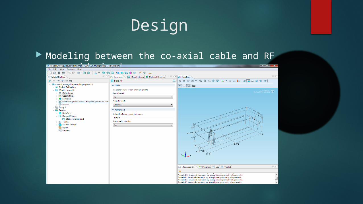
Design
Modeling between the co-axial cable and RF waveguide is done
Design
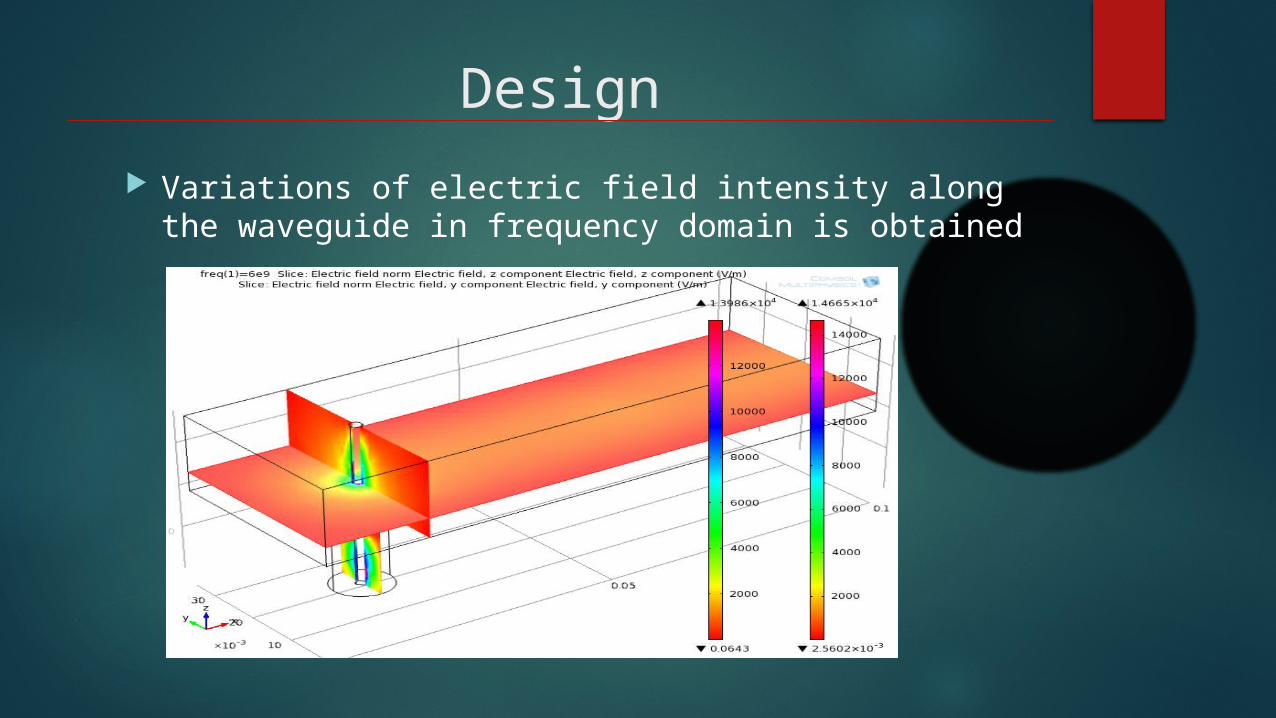
Variations of electric field intensity along the waveguide in frequency domain is obtained

Modeling between waveguide and optical fiber
Since there is no optical fiber pre-defined template, it is constructed by using two hollow cylinders and adding materials to differentiate the core and cladding of optical fiber
Following parameters are considered for the design
H 1[mm] Height, waveguide
L 10[mm] Length, waveguide
L 3[mm] Length, coaxial cable
R 0.25[mm] Outer radius, coaxial cable
r 0.125[mm] Inner radius, coaxial cable
R1 125[um] Cladding radius, optical fiber
R2 8[um] Core radius, optical cable
R.I core = 1.45, R.I cladding = 1.43

Design Material properties are added to the design

Design

Results
Variations of electric field intensity along the waveguide in frequency domain is obtained

Things that have gone wrong
Since there is no laser waveguide pre-defined template, RF waveguide is considered for the initital start-up
RF waveguide deals with the frequency of radio waves, i.e. 40 GHz whereas optical fiber deals with the frequency of THz.
Hence there in no efficient coupling between waveguide and optical fiber in frequency domain
This phenomena is clearly explained in the previous slide as there is no variations in the electric field intensity along the waveguide and optical fiber
Although the design is perfect, boundary conditions and partial differential equations are critical to deal with the design

Corrections that may lead to the success
Design the waveguide by applying proper boundary conditions and partial differential equations of electro-magnetics to activate the laser properties
Apply the equations of wave optics for the propagation of light inside the waveguide
Add physics-
Heat transfer: which is essential for understanding the thermal distribution in the process of coupling between the waveguide
and optical fiber.
Corrections that may lead to the success
Add physics-
Structural Mechanics: Adding thermal stress to the design helps us to understand the real world scenario how stress act as an impairment
and optimize the design to get maximum performance
Good understanding of COMSOL tool to exercise the transition from the raw design to the end product and optimizing the design for the user advantages and objectives.

REFERENCES
1. COMSOL manual, “ Introduction to COMSOL Multiphysics, v 4.3a”, Jan 2013
2. COMSOL software- Wikipedia, “http://en.wikipedia.org/wiki/COMSOL Multiphysics”
COMSOL website,” http://www.comsol.com/”