Embed Size (px)
Citation preview
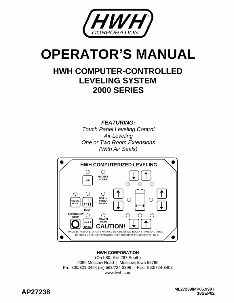
HWH COMPUTER-CONTROLLED
OPERATOR’S MANUAL
DUMP
SECURELY BEFORE REMOVING TIRES OR CRAWLING UNDER VEHICLE.UNDERSTAND OPERATOR’S MANUAL BEFORE USING. BLOCK FRAME AND TIRES
CAUTION!
NOT IN
TRAVEL
EXCESSSLOPE
PARK/BRAKE
RAISE
AIR
HWH COMPUTERIZED LEVELING
2000 SERIESLEVELING SYSTEM
18SEP02ML27239/MP05.998T
TRAVEL
EMERGENCYSTOP
MODE
MODE
AP27238
www.hwh.comPh: 800/321-3494 (or) 563/724-3396 | Fax: 563/724-3408
2096 Moscow Road | Moscow, Iowa 52760(On I-80, Exit 267 South)HWH CORPORATION
(With Air Seals)One or Two Room Extensions
FEATURING:
Air LevelingTouch Panel Leveling Control
CORPORATIONWH RH
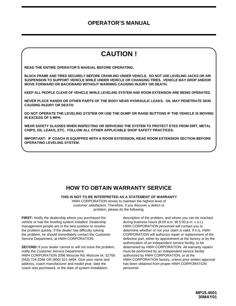
CAUTION !
READ THE ENTIRE OPERATOR’S MANUAL BEFORE OPERATING.
MOVE FORWARD OR BACKWARD WITHOUT WARNING CAUSING INJURY OR DEATH.
CAUSING INJURY OR DEATH.
CHIPS, OIL LEAKS, ETC. FOLLOW ALL OTHER APPLICABLE SHOP SAFETY PRACTICES.
OPERATOR’S MANUAL
MP15.450130MAY01
BLOCK FRAME AND TIRES SECURELY BEFORE CRAWLING UNDER VEHICLE. DO NOT USE LEVELING JACKS OR AIRSUSPENSION TO SUPPORT VEHICLE WHILE UNDER VEHICLE OR CHANGING TIRES. VEHICLE MAY DROP AND/OR
NEVER PLACE HANDS OR OTHER PARTS OF THE BODY NEAR HYDRAULIC LEAKS. OIL MAY PENETRATE SKIN
WEAR SAFETY GLASSES WHEN INSPECTING OR SERVICING THE SYSTEM TO PROTECT EYES FROM DIRT, METAL
IMPORTANT: IF COACH IS EQUIPPED WITH A ROOM EXTENSION, READ ROOM EXTENSION SECTION BEFOREOPERATING LEVELING SYSTEM.
DO NOT OPERATE THE LEVELING SYSTEM OR USE THE DUMP OR RAISE BUTTONS IF THE VEHICLE IS MOVINGIN EXCESS OF 5 MPH.
KEEP ALL PEOPLE CLEAR OF VEHICLE WHILE LEVELING SYSTEM AND ROOM EXTENSION ARE BEING OPERATED.
HOW TO OBTAIN WARRANTY SERVICE
THIS IS NOT TO BE INTERPRETED AS A STATEMENT OF WARRANTYHWH CORPORATION strives to maintain the highest level ofcustomer satisfaction. Therefore, if you discover a defect or
problem, please do the following:
(563) 724-3396 OR (800) 321-3494. Give your name and
coach was purchased, or the date of system installation,
Notify the dealership where you purchased the vehicle or had the leveling system installed. Dealership management people are in the best position to resolve the problem quickly. If the dealer has difficulty solvingthe problem, he should immediately contact the CustomerService Department, at HWH CORPORATION.
If your dealer cannot or will not solve the problem,notify the Customer Service Department:HWH CORPORATION 2096 Moscow Rd. Moscow IA. 52760
address, coach manufacturer and model year, date the
SECOND:
FIRST:
authorization of an independent service facility, to bedefective part, either by appointment at the factory or by theCORPORATION will authorize repair or replacement of thedetermine whether or not your claim is valid. If it is, HWHHWH CORPORATION personnel will contact you toduring business hours (8:00 a.m. till 5:00 p.m. c.s.t.).description of the problem, and where you can be reached
determined by HWH CORPORATION. All warranty repairs must be performed by an independent service facility authorized by HWH CORPORATION, or at the HWH CORPORATION factory, unless prior written approval has been obtained from proper HWH CORPORATION personnel.
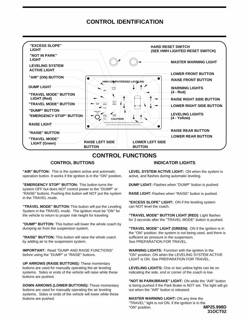
CONTROL IDENTIFICATION
"EMERGENCY STOP" BUTTON
"EXCESS SLOPE"
"NOT IN PARK"
RAISE RIGHT SIDE BUTTON
LOWER RIGHT SIDE BUTTON
LEVELING LIGHTS(4 - Yellow)
WARNING LIGHTS(4 - Red)
RAISE REAR BUTTON
LOWER REAR BUTTON
"AIR" (ON) BUTTON
DUMP LIGHT
"TRAVEL MODE" BUTTON
"TRAVEL MODE"
This button will lower the whole coach bydumping air from the suspension system.
This button will raise the whole coach by adding air to the suspension system.
ON if the leveling systemcan NOT level the coach.
CONTROL BUTTONS
MP25.998D31OCT02
CONTROL FUNCTIONS
LEVELING SYSTEM
"DUMP" BUTTON
RAISE LEFT SIDEBUTTON
LOWER LEFT SIDEBUTTON
RAISE FRONT BUTTON
LOWER FRONT BUTTON
Flashes when "RAISE" button is pushed.
"AIR" BUTTON:
"DUMP" BUTTON:
"RAISE" BUTTON:
UP ARROWS (RAISE BUTTONS):
DOWN ARROWS (LOWER BUTTONS):
IMPORTANT:
DUMP LIGHT:
RAISE LIGHT:
"EXCESS SLOPE" LIGHT:
WARNING LIGHTS:
LEVELING LIGHTS:
"NOT IN PARK/BRAKE" LIGHT:
LIGHT
LIGHT
Flashes when "DUMP" button is pushed.
This is the system active and automatic operation button. It works if the ignition is in the "ON" position.
These momentary buttons are used for manually operating the air leveling systems. Sides or ends of the vehicle will lower while these buttons are pushed.
One or two yellow lights can be on indicating the side, end or corner of the coach is low.
Function with the ignition in the "ON" position. ON when the LEVELING SYSTEM ACTIVE LIGHT is ON. See PREPARATION FOR TRAVEL.
Read "DUMP AND RAISE FUNCTIONS" before using the "DUMP" or "RAISE" buttons.
CAUTION!
HWH COMPUTERIZED LEVELING
UNDERSTAND OPERATOR’S MANUAL BEFORE USING. BLOCK FRAME AND TIRES
SECURELY BEFORE REMOVING TIRES OR CRAWLING UNDER VEHICLE.
NOT IN
PARK /BRAKE
DUMP
RAISE
EMERGENCYSTOP
AIR
TRAVEL
TRAVEL
EXCESS
SLOPE
RAISE LIGHT
"RAISE" BUTTON
"EMERGENCY STOP" BUTTON: This button turns the
"RAISE" buttons. Pushing this button will NOT put the systemsystem OFF but does NOT control power to the "DUMP" or
"TRAVEL MODE" BUTTON:
LEVEL SYSTEM ACTIVE LIGHT: ON when the system isactive, and flashes during automatic leveling.
"TRAVEL MODE" LIGHT (GREEN):
INDICATOR LIGHTS
"TRAVEL MODE" BUTTON LIGHT (RED):
This button will put the LevelingSystem in the TRAVEL mode. The ignition must be "ON" for
ON if the ignition is in the "ON" position, the system is not being used, and there is sufficient air pressure in the suspension.
"TRAVEL MODE" BUTTON
LIGHT (Red)
Light flashes for 3 seconds after the "TRAVEL MODE" button is pushed.
the vehicle to return to proper ride height for traveling.
ON while the "AIR" buttonis being pushed if the Park Brake is NOT set. The light will go out when the "AIR" button is released.
HARD RESET SWITCH(SEE HWH LIGHTED RESET SWITCH)
MASTER WARNING LIGHT
These momentary buttons are used for manually operating the air leveling systems. Sides or ends of the vehicle will raise while these buttons are pushed.
ACTIVE LIGHT
LIGHT (Green)
MODE
MODE
in the TRAVEL mode.
See PREPARATION FOR TRAVEL.
ON any time the MASTER WARNING LIGHT:"TRAVEL" light is not ON, if the ignition is in the "ON" position.
12AUG02MP25.998T
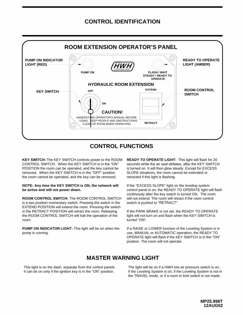
ROOM CONTROL SWITCH:
the room cannot be operated, and the key can be removed.removed. When the KEY SWITCH is in the "OFF" positionPOSITION the room can be operated, and the key cannot beCONTROL SWITCH. When the KEY SWITCH is in the "ON"
The KEY SWITCH controls power to the ROOMKEY SWITCH: READY TO OPERATE LIGHT:
CONTROL FUNCTIONS
KEY SWITCH
USING. KEEP PEOPLE AND OBSTRUCTIONS CLEAR OF ROOM WHEN OPERATING. RETRACT
UNDERSTAND OPERATOR’S MANUAL BEFORE
CAUTION!
ON
LIGHT (AMBER)READY TO OPERATE
ROOM CONTROL
HYDRAULIC ROOM EXTENSIONOFF EXTEND
SWITCH
HHWCORPORATION
R
ROOM EXTENSION OPERATOR’S PANEL
CONTROL IDENTIFICATION
PUMP ON INDICATORLIGHT (RED)
The ROOM CONTROL SWITCHis a two position momentary switch. Pressing the switch in theEXTEND POSITION will extend the room. Pressing the switchin the RETRACT POSITION will retract the room. Releasing the ROOM CONTROL SWITCH will halt the operation of the room.
PUMP ON INDICATOR LIGHT: This light will be on when thepump is running.
This light will flash for 20seconds while the air seal deflates, after the KEY SWITCH is turned on. It will then glow steady. Except for EXCESS SLOPE situations, the room cannot be extended or
If the "EXCESS SLOPE" light on the leveling system control panel is on, the READY TO OPERATE light will flash continously after the key switch is turned ON. The room will not extend. The room will retract if the room control
If the PARK BRAKE is not set, the READY TO OPERATElight will not turn on and flash when the KEY SWITCH isturned "ON".
MASTER WARNING LIGHT
This light is on the dash, separate from the control panels. It can be on only if the ignition key is in the "ON" position.
The light will be on if a HWH low air pressure switch is on,
the TRAVEL mode, or if a room in limit switch is not made.
OPERATE light will flash if the KEY SWITCH is in the "ON"use, MANUAL or AUTOMATIC operation, the READY TO
position. The room will not operate.
If a RAISE or LOWER function of the Leveling System is in
if the Leveling System is on, if the Leveling System is not in
switch is pushed to "RETRACT".
NOTE: Any time the KEY SWITCH is ON, the network will be active and will not power down.
PUMP ONSTEADY / READY TO
FLASH / WAIT
OPERATE
retracted if this light is flashing.
MP25.999514MAR12
CONTROL IDENTIFICATION
PUMP RUN TIME
SYSTEM VARIATIONS FOR PUMP RUN TIME
Contact HWH corporation to get specific information about the system in this vehicle.
No matter what HWH system is on the vehicle, the pump should not be ran for more than four minutes (3" motors) or six minutes (3.7" or 4.5" motors) without allowing the pump motor to cool for thirty minutes. Continuous operation of the pump motor without allowing the motor to cool can damage the pump motor.
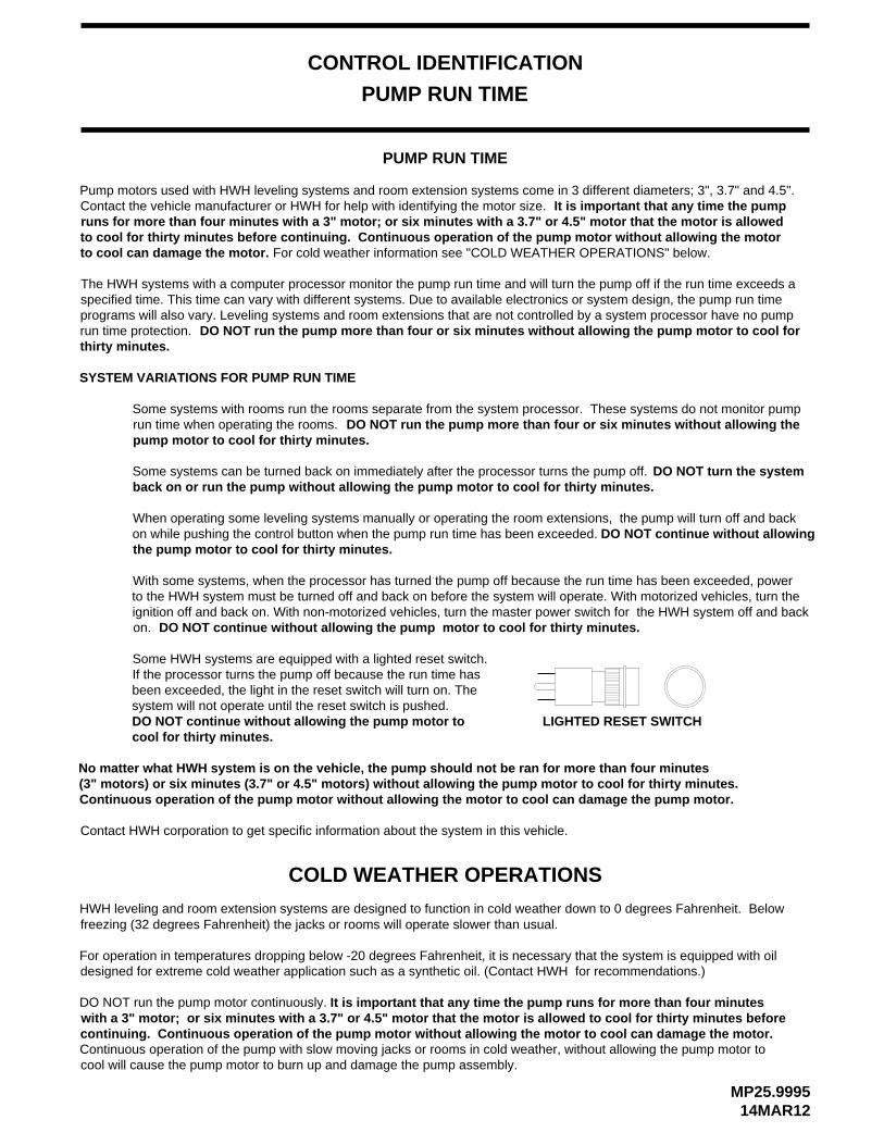
Some HWH systems are equipped with a lighted reset switch. If the processor turns the pump off because the run time has been exceeded, the light in the reset switch will turn on. The
With some systems, when the processor has turned the pump off because the run time has been exceeded, power to the HWH system must be turned off and back on before the system will operate. With motorized vehicles, turn theignition off and back on. With non-motorized vehicles, turn the master power switch for the HWH system off and back
DO NOT continue without allowing the pump motor to cool for thirty minutes.
When operating some leveling systems manually or operating the room extensions, the pump will turn off and back on while pushing the control button when the pump run time has been exceeded.the pump motor to cool for thirty minutes.
Some systems can be turned back on immediately after the processor turns the pump off.back on or run the pump without allowing the pump motor to cool for thirty minutes.
Some systems with rooms run the rooms separate from the system processor. These systems do not monitor pump run time when operating the rooms.pump motor to cool for thirty minutes.
The HWH systems with a computer processor monitor the pump run time and will turn the pump off if the run time exceeds a specified time. This time can vary with different systems. Due to available electronics or system design, the pump run time programs will also vary. Leveling systems and room extensions that are not controlled by a system processor have no pump run time protection.thirty minutes.
Pump motors used with HWH leveling systems and room extension systems come in 3 different diameters; 3", 3.7" and 4.5". Contact the vehicle manufacturer or HWH for help with identifying the motor size.runs for more than four minutes with a 3" motor; or six minutes with a 3.7" or 4.5" motor that the motor is allowed to cool for thirty minutes before continuing. Continuous operation of the pump motor without allowing the motor
PUMP RUN TIME
It is important that any time the pump
to cool can damage the motor.
DO NOT run the pump more than four or six minutes without allowing the pump motor to cool for
DO NOT run the pump more than four or six minutes without allowing the
DO NOT turn the system
DO NOT continue without allowing
on.
system will not operate until the reset switch is pushed.DO NOT continue without allowing the pump motor to cool for thirty minutes.
LIGHTED RESET SWITCH
For cold weather information see "COLD WEATHER OPERATIONS" below.
COLD WEATHER OPERATIONS
HWH leveling and room extension systems are designed to function in cold weather down to 0 degrees Fahrenheit. Below freezing (32 degrees Fahrenheit) the jacks or rooms will operate slower than usual.
For operation in temperatures dropping below -20 degrees Fahrenheit, it is necessary that the system is equipped with oil designed for extreme cold weather application such as a synthetic oil. (Contact HWH for recommendations.)
DO NOT run the pump motor continuously.
Continuous operation of the pump with slow moving jacks or rooms in cold weather, without allowing the pump motor tocool will cause the pump motor to burn up and damage the pump assembly.
It is important that any time the pump runs for more than four minutes
continuing. Continuous operation of the pump motor without allowing the motor to cool can damage the motor. with a 3" motor; or six minutes with a 3.7" or 4.5" motor that the motor is allowed to cool for thirty minutes before
OPERATING PROCEDURES
MP35.152C12AUG02
NETWORK INFORMATION
GENERAL INSTRUCTIONS
Maintain adequate clearance in all directions for vehicles,room extensions, doors, steps, etc.. Vehicle may move in anydirection due to raising or lowering of vehicle during leveling,settling of vehicle, equipment malfunction, etc..
The MASTER WARNING LIGHT will be on if an air bag has low pressure or if a room in limit switch is not made, if theignition is in the "ON" position.
CAUTION: ROOM IS EXTENDED. DO NOT MOVE THE VEHICLE AT
If the Park Brake is not set, the Leveling System cannot be turned ON and the room extension will not operate.
NEUTRAL HOLD OVERRIDE SWITCH
HWH LIGHTED RESET SWITCH
shift out of NEUTRAL, using a key or a screwdriver turn the HOLD OVERRIDE selector switch to the position labeled
If the lighted reset switch is on, the switch must be pushed before any room or the leveling system can be operated.
A network problem with one room will not inhibit the use of
A network problem with the leveling system will not inhibitthe use of the room extensions after the reset switch is
the other rooms or leveling system after the reset switch is
pushed.
pushed.
If a room is not fully retracted, the transmission will notshift out of "NEUTRAL".
If the rooms are fully retracted and the transmission will not"110" position for normal operation.
If the lighted reset switch will not go out when pushed, thereis a problem with the central control module of the networksystem. No rooms or the Leveling System will operate.The vehicle suspension will return to the travel mode if the
IF THE IGNITION IS IN THE "ON" POSITION AND THE LIGHTED RESET SWITCH IS ON, THE VEHICLE CAN RETURN TO RIDE HEIGHT WITHOUT RELEASING THE PARK BRAKE.
ignition key is in the "ON" position.
CAUTION:
HOLD OVERRIDE selector switch should be left in the
"220" the switch is located on the outside of the Central Control Module. This will allow the transmission to be shifted. The system should be serviced as soon as possible. The
If a ROOM CONTROL SWITCH is being pushed, no otherroom or the Leveling System can be operated. If any LevelingSystem raise or lower function is being operated, no room control switch will work.SPEEDS IN EXCESS OF 5 MPH IF THE MASTER
WARNING LIGHT IS ON.
Excessive operation of the hydraulic pump can shut the HWHCAN network down. The lighted reset switch will be on if the ignition is on. The reset button must be pushed before anyoperation can continue. Allow the pump to cool beforecontinuing hydraulic operations.
The HWH 2000 series CAN system is a computerized modular network. It controls all functions of the leveling system and the room extensions. The network is active any time the ignition is in the "ON" position or when any room extension control panel key is "ON". Certain functions and indicator lights for the leveling system will work when the network is active. Certain functions and lights will work ONLY if the the ignition is in the "ON" position to start the function.
The "DUMP" and "RAISE" buttons will function with the leveling system and park brake off, if the ignition is in the "ON" position or if the network is active. See AIR DUMP AND RAISE FUNCTIONS section of this manual.
The HWH lighted reset switch is located on the shifter panel. If there is a failure at any time in the HWH CAN network, the network will shut down. The leveling system and all room extensions will not operate. If the ignition is off, no indicator lights will come on. If the ignition is in the "ON" position, the lighted reset switch and the MASTER WARNING Light will come on.
NOTE: The network will stay active for 10 minutes after the ignition key and all room extension control panel keys have been turned "OFF". If the leveling system was turned "ON", the network will stay active for 10 minutes after automatic leveling is complete or the system goes "EXCESS SLOPE". If manual leveling buttons were used, the network stays active for 10 minutes after the last manual button is released.
DO NOT MOVE THE VEHICLE IF A
OPERATING PROCEDURES
MP35.153C29NOV05
PREPARATION FOR TRAVEL
Visually check that the vehicle is at the proper ride height fortraveling.
The ignition must be in the "ON" position for the vehicle suspension to be in the travel mode. Also the "TRAVEL MODE" button must be pushed or the park brake released for the suspension to be in the travel mode If the Leveling
CAUTION: IT IS THE OPERATOR’S RESPONSIBILITY TO CHECK THAT THE VEHICLE IS AT PROPER RIDE HEIGHT AND ALL SLIDE-OUTS ARE FULLY RETRACTED BEFORE TRAVELING.
Before traveling, the MASTER WARNING light must be offand the "TRAVEL MODE" light must be ON.
System was used.
A lit "TRAVEL MODE" light indicates that the HWH LevelingSystem is in the TRAVEL MODE. It does not indicate that the suspension is at ride height or that the coach is ready to travel.
AUTOMATIC AIR OPERATION
will begin. The system will attempt to level the vehicle by SYSTEM ACTIVE LIGHT will start flashing and air leveling 4. Press the "AIR" button a second time. The LEVELING
The "NOT IN PARK/BRAKE" light will be on while the panel will not turn on if the park brake is not set.
ignition can be moved to the "OFF" position and the use the "AIR" button. Once the operation is started, the
"AIR" button is being pushed.
NOTE: If the ignition key is in the "ON" position, the
NOTE: The ignition must be in the "ON" position to
leveling is complete.When all four yellow LEVEL SENSING lights are out thethe vehicle will be raised by adding air to the air bags.achieved by lowering the vehicle, the low side and/or end of exhausting air from the air bags. If a level position is not
5. When all four yellow level lights are out, the LEVELING SYSTEM ACTIVE LIGHT will stop flashing and start pulsatingdimly. The Leveling System is now in the SLEEP MODE.
operation will continue. If a ROOM CONTROL switch is being pushed, the Leveling System can not be operated.
NOTE: Only one or two yellow LEVEL SENSING lights may be ON at one time.
The vehicle’s engine/ignition may now be turned OFF.
7. If the vehicle needs to be releveled, the CAN Network willbecome active. The LEVELING SYSTEM ACTIVE LIGHT will flash. One or two yellow LEVELING LIGHTS will be ON.When the yellow LEVELING LIGHTS are all out, the LEVELING SYSTEM ACTIVE LIGHT will stop flashing and start pulsating dimly. The Leveling System will remain in theSLEEP MODE with the computer monitoring the LEVELING SENSING UNIT every 30 minutes, releveling the vehicle as needed.
Refer to "DUMP" and "RAISE" FUNCTIONS operatingprocedures when moving the vehicle with the suspensionNOT at the proper ride height.
6. During the Sleep Mode, after 30 minutes the processor checks the Level Sensing Unit inputs. If no input for a yellowlevel light is seen, the processor remains dormant and willrecheck the level unit inputs every thirty minutes. If a yellowlevel light input is on for one minute continuously, theprocessor will relevel the vehicle, then return to the sleep mode.
NOTE: Touch Panel Lights will not be ON unless the system is actively leveling the vehicle.
1. Place the transmission in the proper position for parking and set the park brake. The air leveling system can only be turned on if the ignition is in the "ON" position. Leaving the engine running during leveling is recommended. This will provide a better air supply for leveling. The vehicle will level with the engine shut off, however more time will be required for leveling.
3. Press the "AIR" button once to enter the air mode. The LEVELING SYSTEM ACTIVE LIGHT will glow steady. When the ignition is in the "ON" position, the four red WARNING lights on the panel will come on. This indicates that the height control valves have been locked out. The vehicle should not be moved when these lights are on.
NOTE: After the ignition and all room extension KEY SWITCHES are turned OFF, the CAN Network stays active for 10 minutes before shutting down. Leveling System touch panel lights will stay ON during this time and go out when the CAN Network shuts down. If the Leveling System is in the SLEEP MODE when the Network shuts down, the computer will stay ON. The Leveling System touch panel lights will all be OFF, but the Leveling System will still be in the SLEEP MODE.
Check that all room extensions are fully retracted. The green "TRAVEL MODE" light on the touch panel will not be on if a room is extended. The MASTER WARNING light will be ON. (SEE ROOM RETRACT PROCEDURES)
NOTE: Low air pressure or an extended room can turn the green "TRAVEL MODE" light off and turn the MASTER WARNING light on.
2. Make sure the Tag Lift switch is in the OFF position.
OPERATING PROCEDURES
MP35.174C01DEC05
AUTOMATIC AIR OPERATION (Continued)
vehicle for approximately 15 to 20 minutes. After the 15 to 20 minutes, if a LEVEL SENSING light is still on, the "EXCESS SLOPE" light will come on. The LEVELLIGHT indicator light will go out. The "EXCESS SLOPE"
"EXCESS SLOPE" light is on but they can be retracted.
The "EXCESS SLOPE" light will be on whenever the network is active until the vehicle is leveled with all yellow LEVEL indicator lights off. Releasing the
light will be on whenever the network is active.
NOTE: Room extensions can not be extended if the
EXCESS SLOPE: The system will attempt to level the
NOTE: The CAN Network will stay active for 10 minutesafter releveling the vehicle and then shut down, turning the touch panel lights OFF. This happens every time the system relevels the vehicle.
7. The SLEEP MODE will continue until the "EMERGENCYSTOP" button is pushed or the park brake is released, if theignition is in the "ON" position.
park brake with the ignition on will turn the"EXCESS SLOPE" light off.
OPERATING PROCEDURES
MP35.485Q29JUL04
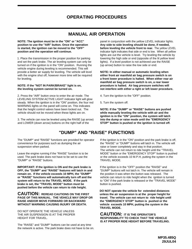
MANUAL AIR OPERATION
NOTE: The ignition must be in the "ON" or "ACC" position to use the "AIR" button. Once the operation is started, the ignition can be moved to the "OFF"
NOTE: If the "NOT IN PARK/BRAKE" light is on,
NOTE: If the "DUMP" or "RAISE" buttons are pushed
the leveling system cannot be turned on.
before leveling the vehicle front to rear. The yellow LEVELindicator light indicates that side or end is low. When all yellowlights are out the vehicle is level. Try leveling the vehicle by
while manually leveling the vehicle with air and the ignition is in the "ON" position, the system will latch into the dump or raise mode until the "EMERGENCY STOP" button is pushed or the ignition is turned off.
4. Turn the ignition to the "OFF" position.
5. Turn the system off.
"DUMP" AND "RAISE" FUNCTIONS
CAUTION: REREAD CAUTIONS ON THE FIRST PAGE OF THIS MANUAL. THE VEHICLE MAY DROP OR RAISE AND/OR MOVE FORWARD OR BACKWARD WITHOUT WARNING CAUSING INJURY OR DEATH.
THE AIR SUSPENSION IS AT THE PROPER DO NOT OPERATE THE VEHICLE UNLESS
RESPONSIBILITY TO CHECK THAT THE VEHICLEIS AT PROPER RIDE HEIGHT BEFORE TRAVELING.
CAUTION: IT IS THE OPERATOR’S
The "RAISE" and "DUMP" buttons can be used at any time the network is active. The park brake does not have to be on.
If the ignition is in the "ON" position and the park brake is off, the "RAISE" or "DUMP" buttons will latch in. The vehicle will raise or lower completely and stay in that position. The vehicle can not return to ride height until the "TRAVELMODE" button or the "EMERGENCY STOP" button is pushed
position and the operation will continue.
The "DUMP" and "RAISE" functions are provided for operator convenience for purposes such as dumping the air suspension when parked.
Leave the engine running if the "RAISE" function is to be used. The park brake does not have to be set to use the "DUMP" or "RAISE" buttons.
HEIGHT FOR TRAVEL.
or the vehicle exceeds 10 M.P.H, putting the system in theTRAVEL MODE.
(up arrow) button to raise the low side or end.lights). If a level position is not achieved use the RAISE
1. Place the transmission in the proper position for parking and set the park brake. The air leveling system can only be turned on if the ignition is in the "ON" position. Running the vehicle engine during leveling is recommended. This will provide a better air supply for leveling. The vehicle will level with the engine shut off, however more time will be required for leveling.
2. Press the "AIR" button once to enter the air mode. The LEVELING SYSTEM ACTIVE LIGHT indicator light will glow steady. When the ignition is in the "ON" position, the four red WARNING lights on the panel will come on. This indicates that the height control valves have been locked out. The vehicle should not be moved when these lights are on.
IMPORTANT: If the ignition is ON and the park brake is OFF, the "DUMP" and "RAISE" features will latch in and remain on. If the vehicle exceeds 10 MPH, the "DUMP" or "RAISE" functions will automatically turn off and the system will return to the TRAVEL MODE. If the park brake is set, the "TRAVEL MODE" button must be pushed before the vehicle can return to ride height.
If the ignition is in the "OFF" position the "RAISE" and "DUMP" buttons will not latch in. The vehicle will remain in the position it was when the button was released. The vehicle can return to ride height when the ignition is turned to "ON" if the park brake is released or the "TRAVEL MODE" button is pushed.
lowering the high side or end (opposite of the lit yellow level
3. The vehicle can now be leveled using the RAISE (up arrow)and LOWER (down arrow) buttons on the right half of the
panel in conjunction with the yellow LEVEL indicator lights. Any side to side leveling should be done, if needed,
NOTE: In either manual or automatic leveling wheneither front air manifold air bag pressure switch is ona front lower procedure is halted. When either rear airmanifold air bag pressure switch is on, a rear lowerprocedure is halted. Air bag pressure switches willnot interfere with either a right or left lower procedure.
DO NOT operate the vehicle for extended distances unless the air suspension is at the proper height for travel. The vehicle can not return to ride height until the "EMERGENCY STOP" button is pushed or the vehicle exceeds 10 MPH, putting the system in the TRAVEL MODE.
OPERATING PROCEDURES
MP35.905C01DEC05
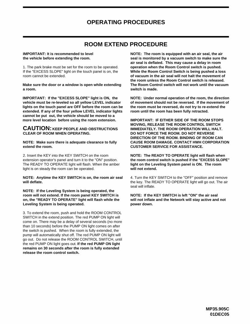
ROOM EXTEND PROCEDURE
1. The park brake must be set for the room to be operated.If the "EXCESS SLOPE" light on the touch panel is on, the room cannot be extended.
CAUTION:KEEP PEOPLE AND OBSTRUCTIONSCLEAR OF ROOM WHEN OPERATING.
NOTE: Make sure there is adequate clearance to fully extend the room.
2. Insert the KEY into the KEY SWITCH on the room extension operator’s panel and turn it to the "ON" position. The READY TO OPERATE light will flash. When the amber light is on steady the room can be operated.
light on the Leveling System panel is ON. The roomthe room control switch is pushed if the "EXCESS SLOPE"
room will not extend. If the room panel KEY SWITCH is
NOTE: The READY TO OPERATE light will flash when
IMPORTANT: IF EITHER SIDE OF THE ROOM STOPSMOVING, RELEASE THE ROOM CONTROL SWITCH
4. Turn the KEY SWITCH to the "OFF" position and removethe key. The READY TO OPERATE light will go out. The air
IMMEDIATELY. THE ROOM OPERATION WILL HALT.
NOTE: Anytime the KEY SWITCH is on, the room air seal
seal will inflate.will deflate.
on, the "READY TO OPERATE" light will flash while the Leveling System is being operated.
NOTE: If the Leveling System is being operated, the NOTE: If the KEY SWITCH is left "ON" the air seal will not inflate and the Network will stay active and not
DO NOT FORCE THE ROOM. DO NOT REVERSE DIRECTION OF THE ROOM. BINDING OF ROOM CAN CAUSE ROOM DAMAGE. CONTACT HWH CORPORATIONCUSTOMER SERVICE FOR ASSISTANCE.
NOTE: Under normal operation of the room, the directionof movement should not be reversed. If the movement ofthe room must be reversed, do not try to re-extend the room until the room has been fully retracted.
IMPORTANT: If the "EXCESS SLOPE" light is ON, thevehicle must be re-leveled so all yellow LEVEL indicator lights on the touch panel are OFF before the room can be extended. If any of the four yellow LEVEL indicator lights cannot be put out, the vehicle should be moved to a more level location before using the room extension.
power down.
will not extend.
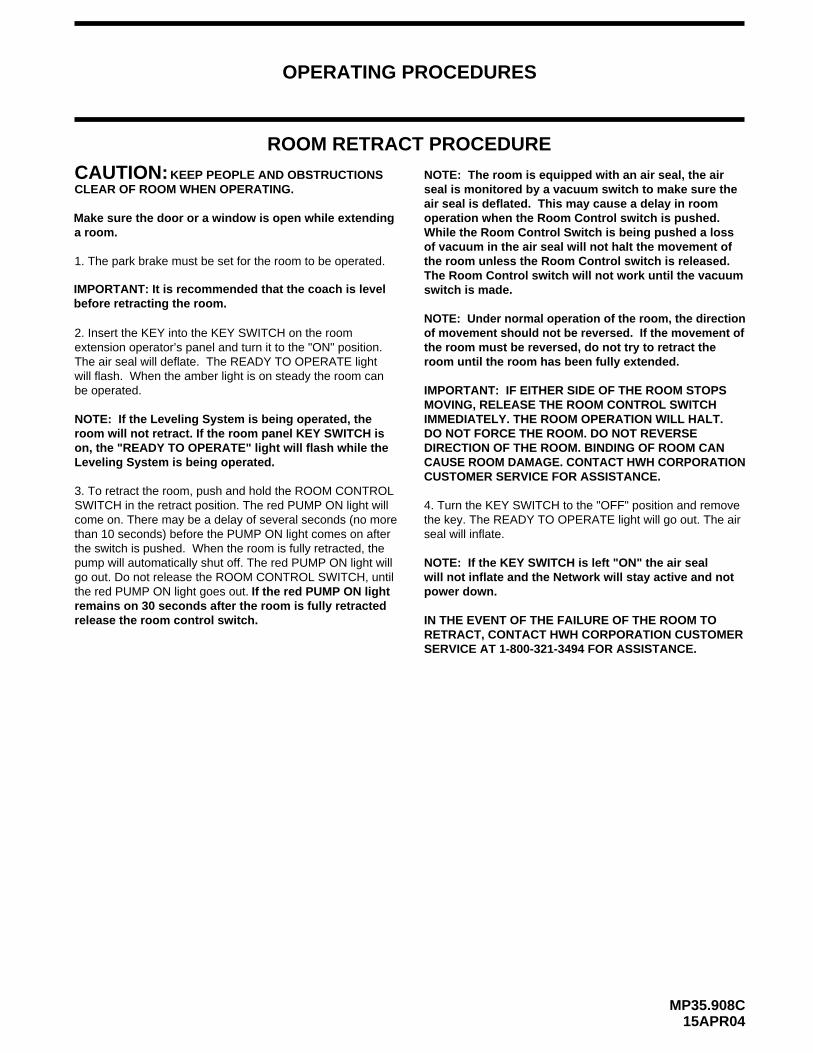
Make sure the door or a window is open while extending a room.
than 10 seconds) before the PUMP ON light comes on after
the red PUMP ON light goes out.
release the room control switch.remains on 30 seconds after the room is fully extended
go out. Do not release the ROOM CONTROL SWITCH, until pump will automatically shut off. The red PUMP ON light will the switch is pushed. When the room is fully extended, the
If the red PUMP ON light
3. To extend the room, push and hold the ROOM CONTROL
come on. There may be a delay of several seconds (no moreSWITCH in the extend position. The red PUMP ON light will
The Room Control switch will not work until the vacuum the room unless the Room Control switch is released. of vacuum in the air seal will not halt the movement of While the Room Control Switch is being pushed a loss operation when the Room Control switch is pushed.air seal is deflated. This may cause a delay in room seal is monitored by a vacuum switch to make sure theNOTE: The room is equipped with an air seal, the air
switch is made.
the vehicle before extending the room.IMPORTANT: It is recommended to level
OPERATING PROCEDURES
MP35.908C15APR04
ROOM RETRACT PROCEDURE
1. The park brake must be set for the room to be operated.
CAUTION:KEEP PEOPLE AND OBSTRUCTIONSCLEAR OF ROOM WHEN OPERATING.
2. Insert the KEY into the KEY SWITCH on the room extension operator’s panel and turn it to the "ON" position. The air seal will deflate. The READY TO OPERATE light will flash. When the amber light is on steady the room can
room will not retract. If the room panel KEY SWITCH is
IMPORTANT: IF EITHER SIDE OF THE ROOM STOPSMOVING, RELEASE THE ROOM CONTROL SWITCH
4. Turn the KEY SWITCH to the "OFF" position and removethe key. The READY TO OPERATE light will go out. The air
IMMEDIATELY. THE ROOM OPERATION WILL HALT.
seal will inflate.
on, the "READY TO OPERATE" light will flash while the Leveling System is being operated.
NOTE: If the Leveling System is being operated, the
NOTE: If the KEY SWITCH is left "ON" the air seal will not inflate and the Network will stay active and not
DO NOT FORCE THE ROOM. DO NOT REVERSE DIRECTION OF THE ROOM. BINDING OF ROOM CAN CAUSE ROOM DAMAGE. CONTACT HWH CORPORATIONCUSTOMER SERVICE FOR ASSISTANCE.
NOTE: Under normal operation of the room, the directionof movement should not be reversed. If the movement ofthe room must be reversed, do not try to retract the room until the room has been fully extended.
power down.
Make sure the door or a window is open while extending a room.
be operated.
IN THE EVENT OF THE FAILURE OF THE ROOM TORETRACT, CONTACT HWH CORPORATION CUSTOMERSERVICE AT 1-800-321-3494 FOR ASSISTANCE.
SWITCH in the retract position. The red PUMP ON light willcome on. There may be a delay of several seconds (no morethan 10 seconds) before the PUMP ON light comes on after the switch is pushed. When the room is fully retracted, the pump will automatically shut off. The red PUMP ON light will go out. Do not release the ROOM CONTROL SWITCH, until
If the red PUMP ON light remains on 30 seconds after the room is fully retracted
3. To retract the room, push and hold the ROOM CONTROL
release the room control switch.
the red PUMP ON light goes out.
NOTE: The room is equipped with an air seal, the airseal is monitored by a vacuum switch to make sure theair seal is deflated. This may cause a delay in room operation when the Room Control switch is pushed.While the Room Control Switch is being pushed a loss of vacuum in the air seal will not halt the movement of the room unless the Room Control switch is released. The Room Control switch will not work until the vacuum switch is made.IMPORTANT: It is recommended that the coach is level
before retracting the room.
MP35.952D01MAY02
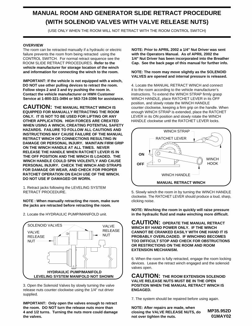
MANUAL ROOM AND GENERATOR SLIDE RETRACT PROCEDURE
OVERVIEW
1. Retract jacks following the LEVELING SYSTEM RETRACT PROCEDURE.
2. Locate the HYDRAULIC PUMP/MANIFOLD unit.
VALVES are opened and internal pressure is released.
WINCH
WINCH STRAP
WINCH HANDLE
RATCHET LEVER
HOOK
MANUAL RETRACT WINCH
5. Slowly winch the room in by turning the WINCH HANDLEclockwise. The RATCHET LEVER should produce a loud, sharp,clicking noise.
in the hydraulic fluid and make winching more difficult.
CAUTION:
ON
OFF
HYDRAULIC PUMP/MANIFOLD
NOTE: The room may move slightly as the SOLENOID
NOTE :
NOTE: Winching the room in quickly will raise pressure
IMPORTANT:
6. When the room is fully retracted, engage the room lockingdevices. Leave the retract winch engaged and the solenoid
CAUTION: THE ROOM EXTENSION SOLENOID VALVE RELEASE NUTS MUST BE IN THE OPEN POSITION WHEN THE MANUAL RETRACT WINCH IS
7. The system should be repaired before using again.
CAUTION: THE MANUAL RETRACT WINCH IS
OPERATE THE MANUAL RETRACT WINCH BY HAND POWER ONLY. IF THE WINCH CANNOT BE CRANKED EASILY WITH ONE HAND IT IS PROBABLY OVERLOADED. IF WINCHING BECOMES TOO DIFFICULT STOP AND CHECK FOR OBSTRUCTIONS OR RESTRICTIONS ON THE ROOM AND ROOM
LEVELING SYSTEM MANIFOLD NOT SHOWN
SOLENOID VALVES
VALVE RELEASENUT
NUT
VALVE RELEASE
3. Open the Solenoid Valves by slowly turning the valve release nuts counter clockwise using the 1/4" nut driver
Only open the valves enough to retractNOTE: After repairs are made, when closing the VALVE RELEASE NUTS, do
When manually retracting the room, make surethe jacks are retracted before retracting the room.
EQUIPPED FOR MANUALLY RETRACTING THE ROOM ONLY. IT IS NOT TO BE USED FOR LIFTING OR ANY OTHER APPLICATION. HIGH FORCES ARE CREATED WHEN USING A WINCH, CREATING POTENTIAL SAFETY HAZARDS. FAILURE TO FOLLOW ALL CAUTIONS AND INSTRUCTIONS MAY CAUSE FAILURE OF THE MANUAL RETRACT WINCH OR CONNECTIONS RESULTING IN DAMAGE OR PERSONAL INJURY. MAINTAIN FIRM GRIP ON THE WINCH HANDLE AT ALL TIMES. NEVER RELEASE THE HANDLE WHEN RATCHET LEVER IS IN THE OFF POSITION AND THE WINCH IS LOADED. THE WINCH HANDLE COULD SPIN VIOLENTLY AND CAUSE PERSONAL INJURY. CHECK THE WINCH AND STRAPS FOR DAMAGE OR WEAR, AND CHECK FOR PROPER RATCHET OPERATION ON EACH USE OF THE WINCH. DO NOT USE IF DAMAGED OR WORN.
supplied.
the room. DO NOT turn the release nuts more than4 and 1/2 turns. Turning the nuts more could damagethe valves.
with the Operators Manual. As of APRIL 2002 the NOTE: Prior to APRIL 2002 a 1/4" Nut Driver was sent
Cap. See the back page of this manual for further info.1/4" Nut Driver has been incorporated into the Breather
4. Locate the MANUAL RETRACT WINCH and connect it to the room according to the vehicle manufacturer’s instructions. To extend the WINCH STRAP firmly grasp WINCH HANDLE, place RATCHET LEVER in its OFF position, and slowly rotate the WINCH HANDLE counter clockwise, keeping a firm grip on the handle. When enough WINCH STRAP is extended, place the RATCHET LEVER in its ON position and slowly rotate the WINCH HANDLE clockwise until the RATCHET LEVER locks.
EXTENSION MECHANISM.
valves open.
ENGAGED.
(WITH SOLENOID VALVES WITH VALVE RELEASE NUTS)(USE ONLY WHEN THE ROOM WILL NOT RETRACT WITH THE ROOM CONTROL SWITCH)
not over tighten the nuts.
IMPORTANT: If the vehicle is not equipped with a winch,DO NOT use other pulling devices to retract the room.Follow steps 2 and 3 and try pushing the room in.Contact the vehicle manufacturer or HWH CustomerService at 1-800-321-3494 or 563-724-3396 for assistance.
The room can be retracted manually if a hydraulic or electric failure prevents the room from being retracted using the CONTROL SWITCH. For normal retract sequence see the ROOM SLIDE RETRACT PROCEDURES. Refer to the vehicle manufacturer for storage location of the winch and information for connecting the winch to the room.
MP45.998C29NOV05
MAINTENANCE
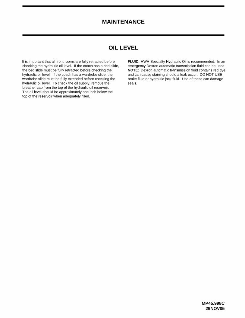
OIL LEVEL
FLUID: HWH Specialty Hydraulic Oil is recommended. In an
brake fluid or hydraulic jack fluid. Use of these can damage and can cause staining should a leak occur. DO NOT USE
Dexron automatic transmission fluid contains red dyeemergency Dexron automatic transmission fluid can be used.
seals.
NOTE:
It is important that all front rooms are fully retracted before checking the hydraulic oil level. If the coach has a bed slide, the bed slide must be fully retracted before checking the hydraulic oil level. If the coach has a wardrobe slide, the wardrobe slide must be fully extended before checking the hydraulic oil level. To check the oil supply, remove the breather cap from the top of the hydraulic oil reservoir. The oil level should be approximately one inch below the top of the reservoir when adequately filled.
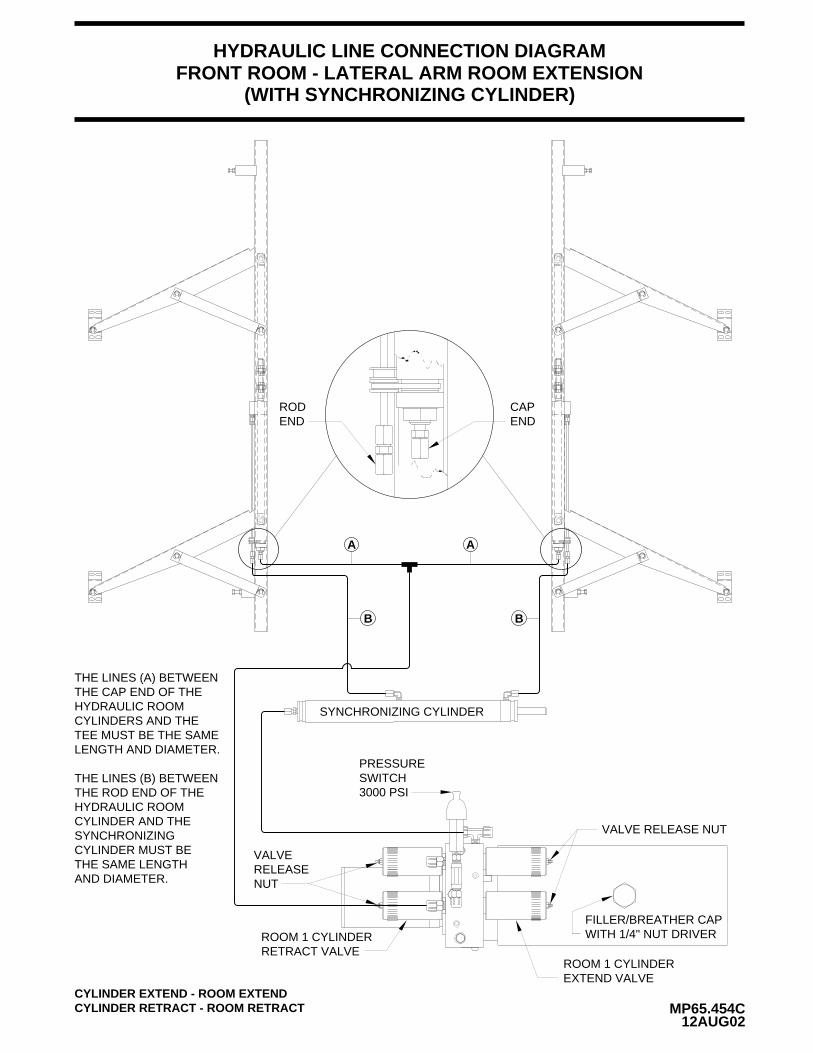
FRONT ROOM - LATERAL ARM ROOM EXTENSIONHYDRAULIC LINE CONNECTION DIAGRAM
MP65.454C12AUG02
(WITH SYNCHRONIZING CYLINDER)
RODEND
CAPEND
SYNCHRONIZING CYLINDER
A
B
A
B
THE LINES (A) BETWEENTHE CAP END OF THEHYDRAULIC ROOMCYLINDERS AND THETEE MUST BE THE SAMELENGTH AND DIAMETER.
THE LINES (B) BETWEENTHE ROD END OF THEHYDRAULIC ROOMCYLINDER AND THESYNCHRONIZINGCYLINDER MUST BETHE SAME LENGTHAND DIAMETER.
PRESSURESWITCH3000 PSI
FILLER/BREATHER CAPWITH 1/4" NUT DRIVER
VALVE RELEASE NUT
ROOM 1 CYLINDEREXTEND VALVE
RETRACT VALVEROOM 1 CYLINDER
VALVERELEASENUT
CYLINDER EXTEND - ROOM EXTENDCYLINDER RETRACT - ROOM RETRACT
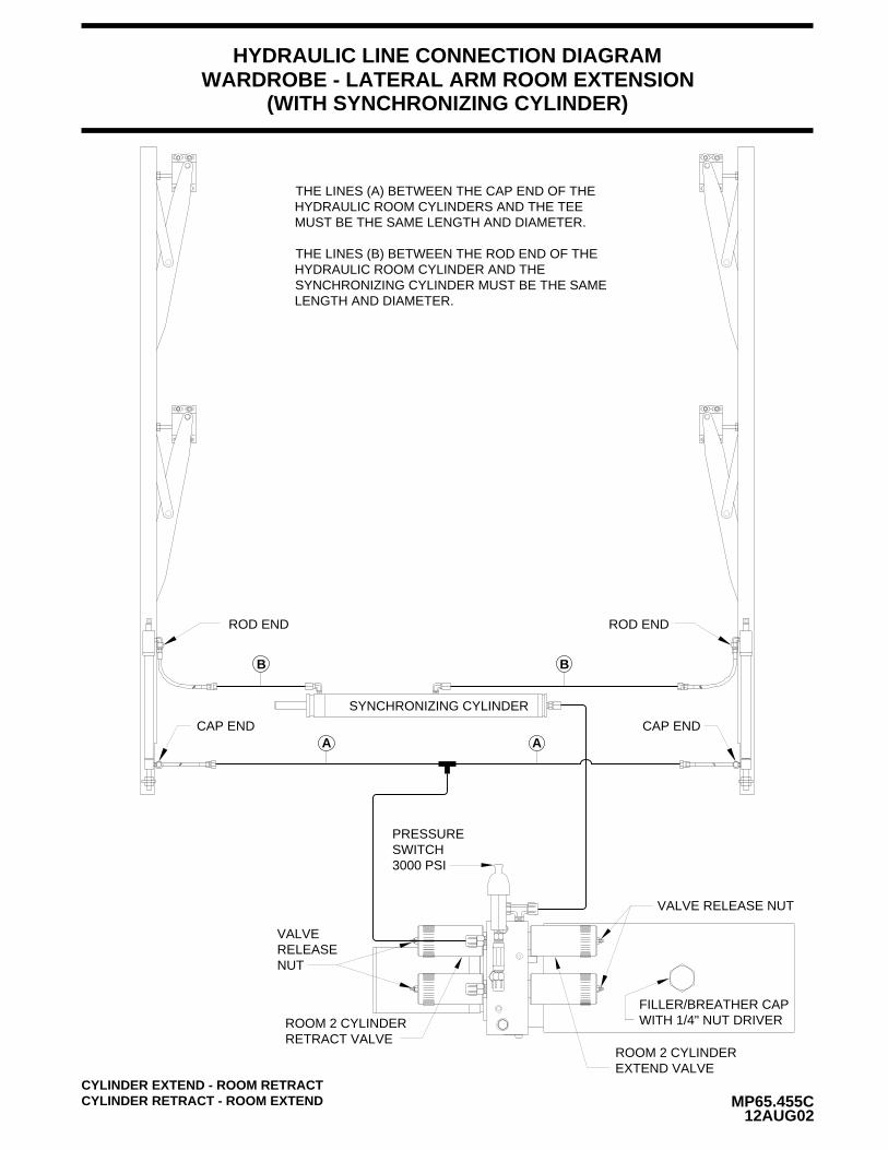
WARDROBE - LATERAL ARM ROOM EXTENSIONHYDRAULIC LINE CONNECTION DIAGRAM
MP65.455C12AUG02
(WITH SYNCHRONIZING CYLINDER)
SYNCHRONIZING CYLINDER
A
B
A
B
PRESSURESWITCH3000 PSI
FILLER/BREATHER CAPWITH 1/4" NUT DRIVER
VALVE RELEASE NUT
ROOM 2 CYLINDEREXTEND VALVE
RETRACT VALVEROOM 2 CYLINDER
VALVERELEASENUT
CYLINDER EXTEND - ROOM RETRACTCYLINDER RETRACT - ROOM EXTEND
CAP END
ROD END ROD END
CAP END
THE LINES (A) BETWEEN THE CAP END OF THE HYDRAULIC ROOM CYLINDERS AND THE TEE MUST BE THE SAME LENGTH AND DIAMETER.
THE LINES (B) BETWEEN THE ROD END OF THE HYDRAULIC ROOM CYLINDER AND THE SYNCHRONIZING CYLINDER MUST BE THE SAME LENGTH AND DIAMETER.
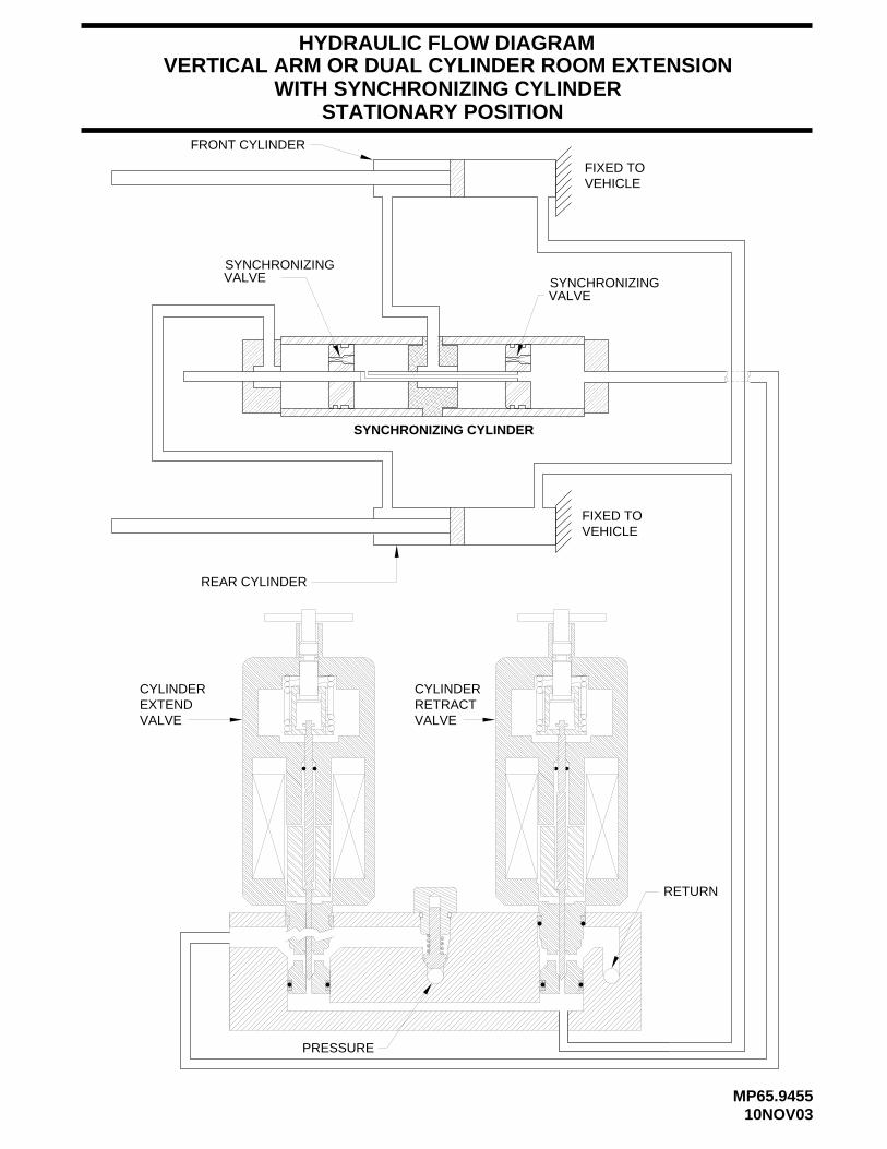
HYDRAULIC FLOW DIAGRAM
MP65.945510NOV03
FIXED TOVEHICLE
FRONT CYLINDER
VERTICAL ARM OR DUAL CYLINDER ROOM EXTENSION
REAR CYLINDER
VEHICLEFIXED TO
STATIONARY POSITION
PRESSURE
RETURN
SYNCHRONIZING CYLINDER
SYNCHRONIZINGVALVE
SYNCHRONIZINGVALVE
WITH SYNCHRONIZING CYLINDER
EXTENDCYLINDER
VALVERETRACTVALVE
CYLINDER
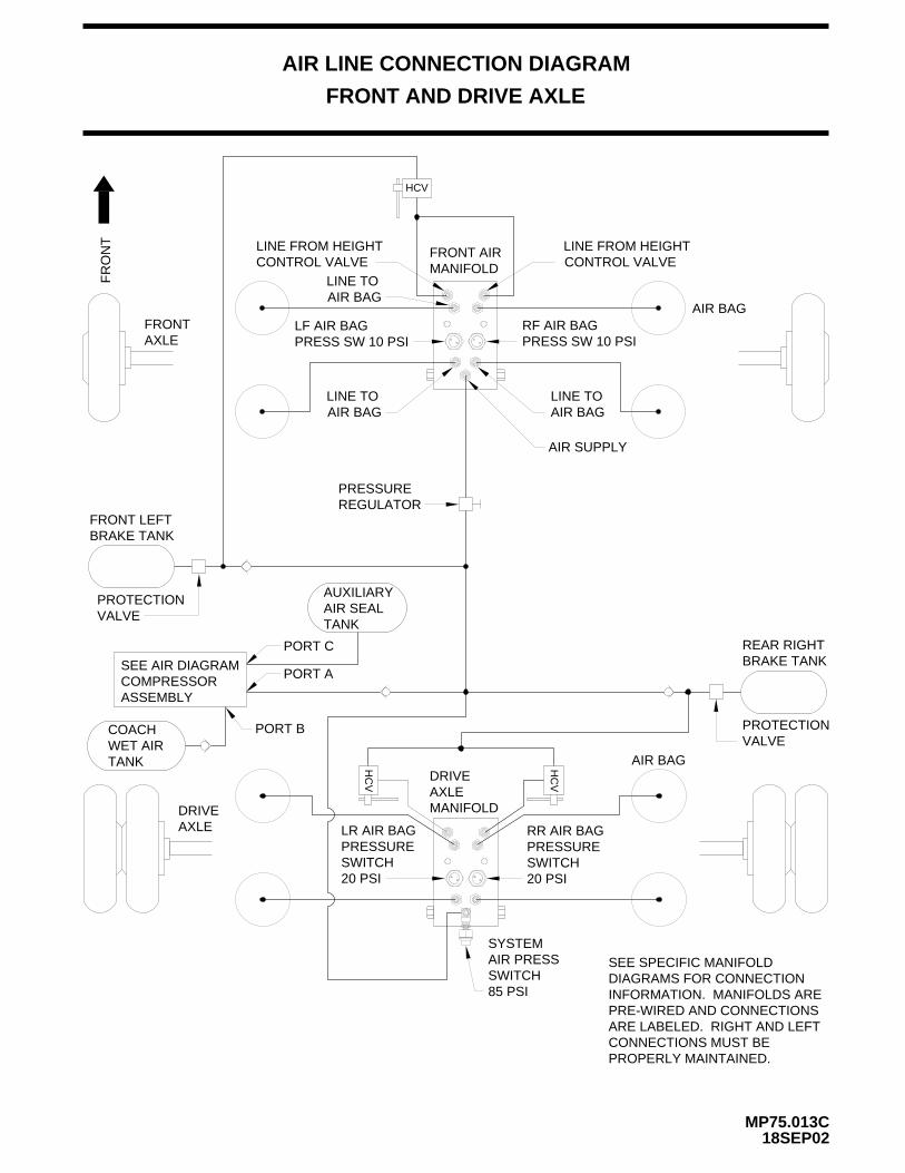
AIR LINE CONNECTION DIAGRAM
FRONT AND DRIVE AXLE
18SEP02MP75.013C
HC
V
HCV
HC
V
FRONT AIRMANIFOLD
LINE FROM HEIGHTCONTROL VALVE
LINE FROM HEIGHTCONTROL VALVE
LF AIR BAGPRESS SW 10 PSI
LINE TOAIR BAG
AIR SUPPLY
LINE TOAIR BAG
AXLEDRIVE
AXLEFRONT
FR
ON
T
BRAKE TANKREAR RIGHT
AXLEDRIVE
MANIFOLD
LR AIR BAGPRESSURESWITCH
SYSTEMAIR PRESSSWITCH85 PSI
AIR BAG
20 PSI
RR AIR BAGPRESSURESWITCH20 PSI
COACHWET AIRTANK
SEE AIR DIAGRAMCOMPRESSORASSEMBLY
PORT B
PORT C
PORT A
AUXILIARYAIR SEALTANK
PROTECTIONVALVE
BRAKE TANKFRONT LEFT
PROTECTIONVALVE
AIR BAG
PRESSUREREGULATOR
PRESS SW 10 PSIRF AIR BAG
AIR BAGLINE TO
SEE SPECIFIC MANIFOLDDIAGRAMS FOR CONNECTIONINFORMATION. MANIFOLDS AREPRE-WIRED AND CONNECTIONSARE LABELED. RIGHT AND LEFTCONNECTIONS MUST BEPROPERLY MAINTAINED.
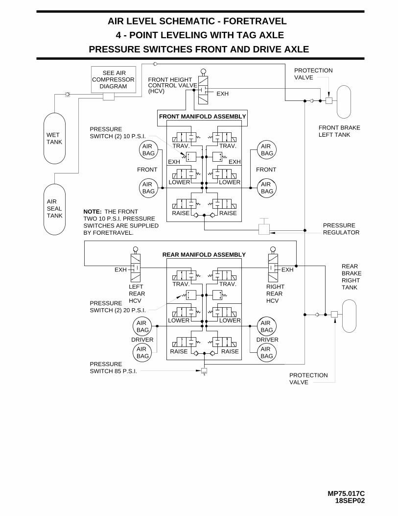
AIR LEVEL SCHEMATIC - FORETRAVEL
4 - POINT LEVELING WITH TAG AXLE
MP75.017C18SEP02
PRESSURE SWITCHES FRONT AND DRIVE AXLE
REAR MANIFOLD ASSEMBLY
EXHEXH
LOWER
RAISE
TRAV.
LOWER
RAISE
TRAV.
COMPRESSORDIAGRAM
SEE AIR
RAISE RAISE
FRONT MANIFOLD ASSEMBLY
EXH
LOWER
TRAV.
LOWER
TRAV.
EXH
(HCV)CONTROL VALVEFRONT HEIGHT
EXH
FRONT
DRIVER
AIRBAG
BAGAIR
BAGAIR AIR
BAG
AIRBAG
BAGAIR AIR
BAG
AIRBAG
DRIVER
FRONT
PROTECTIONVALVE
FRONT BRAKELEFT TANK
PRESSUREREGULATOR
REARBRAKERIGHTTANK
PROTECTIONVALVE
PRESSURE SWITCH (2) 10 P.S.I.
NOTE: THE FRONT TWO 10 P.S.I. PRESSURESWITCHES ARE SUPPLIEDBY FORETRAVEL.
SWITCH 85 P.S.I.PRESSURE
WETTANK
AIRSEALTANK
LEFTREARHCV
RIGHTREARHCV
SWITCH (2) 20 P.S.I.PRESSURE
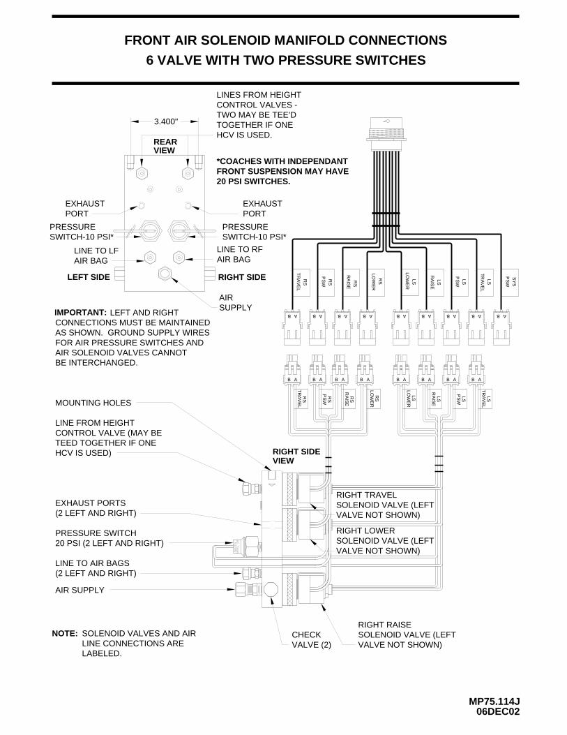
FRONT AIR SOLENOID MANIFOLD CONNECTIONS
6 VALVE WITH TWO PRESSURE SWITCHES
AB B A B A BAB A B A BAB A B A
B A B A B A B A B A B A B A B A
RS
TR
AV
EL
LSLO
WE
R
RS
PS
W RS
RA
ISE
RS
LOW
ER
LSR
AIS
E
LST
RA
VE
L
LSP
SW
SY
SP
SW
RS
TR
AV
EL
LSLO
WE
R
RS
PS
W
RS
RA
ISE
RS
LOW
ER
LSR
AIS
E
LSP
SW
LST
RA
VE
L
REAR
LEFT SIDE RIGHT SIDE
PRESSURESWITCH-10 PSI*
3.400"
PRESSURESWITCH-10 PSI*
AIR BAGLINE TO LF LINE TO RF
AIR BAG
EXHAUSTPORT
EXHAUSTPORT
LINES FROM HEIGHT CONTROL VALVES -TWO MAY BE TEE’D TOGETHER IF ONEHCV IS USED.
AIR SUPPLY
RIGHT RAISESOLENOID VALVE (LEFTVALVE NOT SHOWN)
VALVE NOT SHOWN)SOLENOID VALVE (LEFTRIGHT LOWER
VALVE NOT SHOWN)SOLENOID VALVE (LEFTRIGHT TRAVEL
IMPORTANT: LEFT AND RIGHTCONNECTIONS MUST BE MAINTAINEDAS SHOWN. GROUND SUPPLY WIRESFOR AIR PRESSURE SWITCHES ANDAIR SOLENOID VALVES CANNOT BE INTERCHANGED.
CHECKVALVE (2)
RIGHT SIDE
VIEW
VIEW
MOUNTING HOLES
LINE FROM HEIGHTCONTROL VALVE (MAY BETEED TOGETHER IF ONE HCV IS USED)
EXHAUST PORTS(2 LEFT AND RIGHT)
PRESSURE SWITCH20 PSI (2 LEFT AND RIGHT)
LINE TO AIR BAGS(2 LEFT AND RIGHT)
AIR SUPPLY
NOTE: SOLENOID VALVES AND AIRLINE CONNECTIONS ARE LABELED.
06DEC02MP75.114J
*COACHES WITH INDEPENDANTFRONT SUSPENSION MAY HAVE 20 PSI SWITCHES.
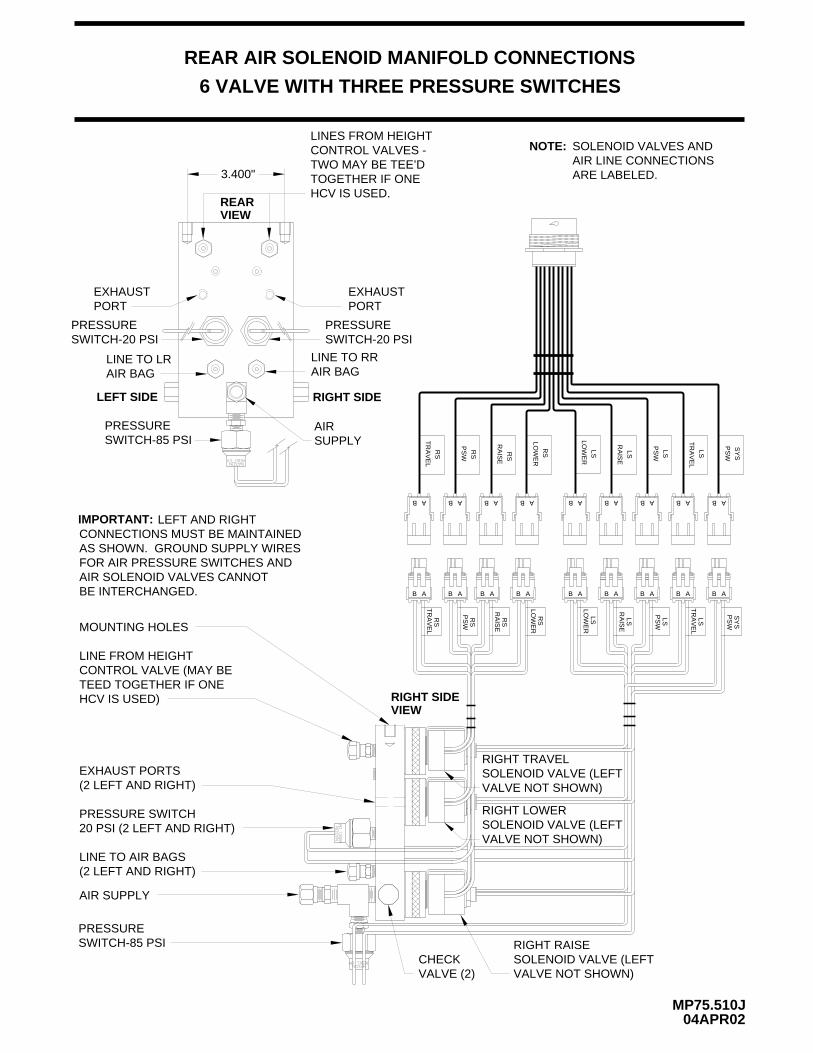
REAR AIR SOLENOID MANIFOLD CONNECTIONS
6 VALVE WITH THREE PRESSURE SWITCHES
AB B A B A BAB A B A BAB A B A
B A B A B A B A B A B A B A B A AB
RS
TR
AV
EL
LSLO
WE
R
RS
PS
W RS
RA
ISE
RS
LOW
ER
LSR
AIS
E
LST
RA
VE
L
LSP
SW
SY
SP
SW
RS
TR
AV
EL
LSLO
WE
R
RS
PS
W
RS
RA
ISE
RS
LOW
ER
LSR
AIS
E
LSP
SW
LST
RA
VE
L
SY
SP
SW
REAR
LEFT SIDE RIGHT SIDE
PRESSURESWITCH-20 PSI
SWITCH-85 PSIPRESSURE
3.400"
PRESSURESWITCH-20 PSI
AIR BAGLINE TO LR LINE TO RR
AIR BAG
EXHAUSTPORT
EXHAUSTPORT
LINES FROM HEIGHT CONTROL VALVES -TWO MAY BE TEE’D TOGETHER IF ONEHCV IS USED.
AIR SUPPLY
RIGHT RAISESOLENOID VALVE (LEFTVALVE NOT SHOWN)
VALVE NOT SHOWN)SOLENOID VALVE (LEFTRIGHT LOWER
VALVE NOT SHOWN)SOLENOID VALVE (LEFTRIGHT TRAVEL
IMPORTANT: LEFT AND RIGHTCONNECTIONS MUST BE MAINTAINEDAS SHOWN. GROUND SUPPLY WIRESFOR AIR PRESSURE SWITCHES ANDAIR SOLENOID VALVES CANNOT BE INTERCHANGED.
CHECKVALVE (2)
VIEW
(2 LEFT AND RIGHT)LINE TO AIR BAGS
20 PSI (2 LEFT AND RIGHT)PRESSURE SWITCH
(2 LEFT AND RIGHT)EXHAUST PORTS
TEED TOGETHER IF ONE CONTROL VALVE (MAY BELINE FROM HEIGHT
MOUNTING HOLES
AIR SUPPLY
HCV IS USED)VIEWRIGHT SIDE
SWITCH-85 PSIPRESSURE
NOTE: SOLENOID VALVES ANDAIR LINE CONNECTIONSARE LABELED.
04APR02MP75.510J
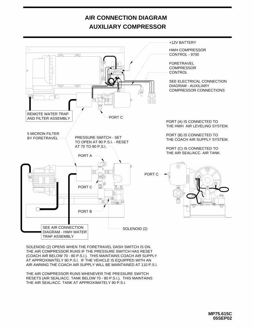
AIR CONNECTION DIAGRAM
AUXILIARY COMPRESSOR
MP75.615C05SEP02
HWH COMPRESSORCONTROL - 9700
FORETRAVEL COMPRESSORCONTROL
SEE ELECTRICAL CONNECTIONDIAGRAM - AUXILIARY
PORT (A) IS CONNECTED TO THE HWH AIR LEVELING SYSTEM.
PORT (B) IS CONNECTED TO THE COACH AIR SUPPLY SYSTEM.
PORT (C) IS CONNECTED TO THE AIR SEAL/ACC. AIR TANK.
SOLENOID (2) OPENS WHEN THE FORETRAVEL DASH SWITCH IS ON.THE AIR COMPRESSOR RUNS IF THE PRESSURE SWITCH HAS RESET(COACH AIR BELOW 70 - 80 P.S.I.). THIS MAINTAINS COACH AIR SUPPLYAT APPROXIMATELY 90 P.S.I. IF THE VEHICLE IS EQUIPPED WITH AN
THE AIR COMPRESSOR RUNS WHENEVER THE PRESSURE SWITCHRESETS (AIR SEAL/ACC. TANK BELOW 70 - 80 P.S.I.). THIS MAINTAINSTHE AIR SEAL/ACC. TANK AT APPROXIMATELY 90 P.S.I.
+12V BATTERY
AIR AWNING THE COACH AIR SUPPLY WILL BE MAINTAINED AT 110 P.S.I.
REMOTE WATER TRAPAND FILTER ASSEMBLY PORT C
5 MICRON FILTERBY FORETRAVEL
COMPRESSOR CONNECTIONS
PORT A
PORT C
PORT B
PRESSURE SWITCH - SETTO OPEN AT 90 P.S.I. - RESETAT 70 TO 80 P.S.I.
SEE AIR CONNECTIONDIAGRAM - HWH WATERTRAP ASSEMBLY
SOLENOID (2)
PORT C
MP75.620C03FEB03
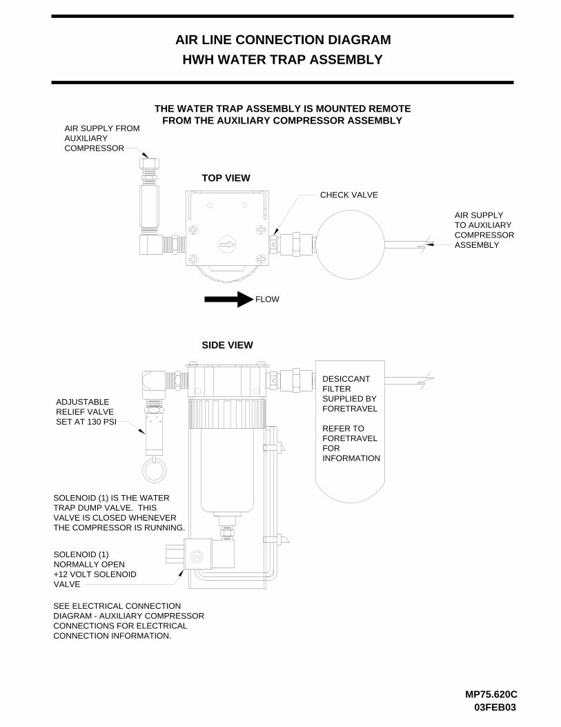
AIR LINE CONNECTION DIAGRAM
HWH WATER TRAP ASSEMBLY
TOP VIEW
SIDE VIEW
AIR SUPPLY FROMAUXILIARY
ADJUSTABLERELIEF VALVESET AT 130 PSI
NORMALLY OPEN+12 VOLT SOLENOIDVALVE
FLOW
CHECK VALVE
COMPRESSOR
AIR SUPPLYTO AUXILIARYCOMPRESSORASSEMBLY
SOLENOID (1) IS THE WATERTRAP DUMP VALVE. THISVALVE IS CLOSED WHENEVERTHE COMPRESSOR IS RUNNING.
SOLENOID (1)
SEE ELECTRICAL CONNECTIONDIAGRAM - AUXILIARY COMPRESSORCONNECTIONS FOR ELECTRICALCONNECTION INFORMATION.
DESICCANTFILTERSUPPLIED BYFORETRAVEL
REFER TOFORETRAVELFORINFORMATION
THE WATER TRAP ASSEMBLY IS MOUNTED REMOTEFROM THE AUXILIARY COMPRESSOR ASSEMBLY
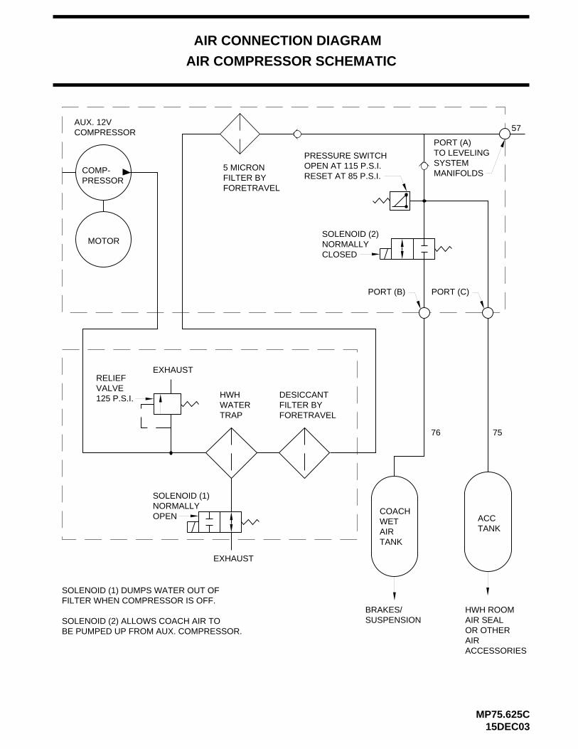
AIR CONNECTION DIAGRAM
AIR COMPRESSOR SCHEMATIC
COMP-PRESSOR
MOTOR
COACHWETAIRTANK
TANKACC
BRAKES/ HWH ROOMAIR SEALOR OTHERAIRACCESSORIES
EXHAUST
EXHAUST
SOLENOID (1)NORMALLYOPEN
SOLENOID (2)
CLOSEDNORMALLY
RELIEFVALVE125 P.S.I.
RESET AT 85 P.S.I.OPEN AT 115 P.S.I.PRESSURE SWITCH
PORT (C)
AUX. 12VCOMPRESSOR
SOLENOID (1) DUMPS WATER OUT OFFILTER WHEN COMPRESSOR IS OFF.
SOLENOID (2) ALLOWS COACH AIR TO BE PUMPED UP FROM AUX. COMPRESSOR.
PORT (A)TO LEVELINGSYSTEMMANIFOLDS
PORT (B)
SUSPENSION
HWHWATERTRAP
DESICCANTFILTER BYFORETRAVEL
76 75
5 MICRONFILTER BYFORETRAVEL
57
15DEC03MP75.625C
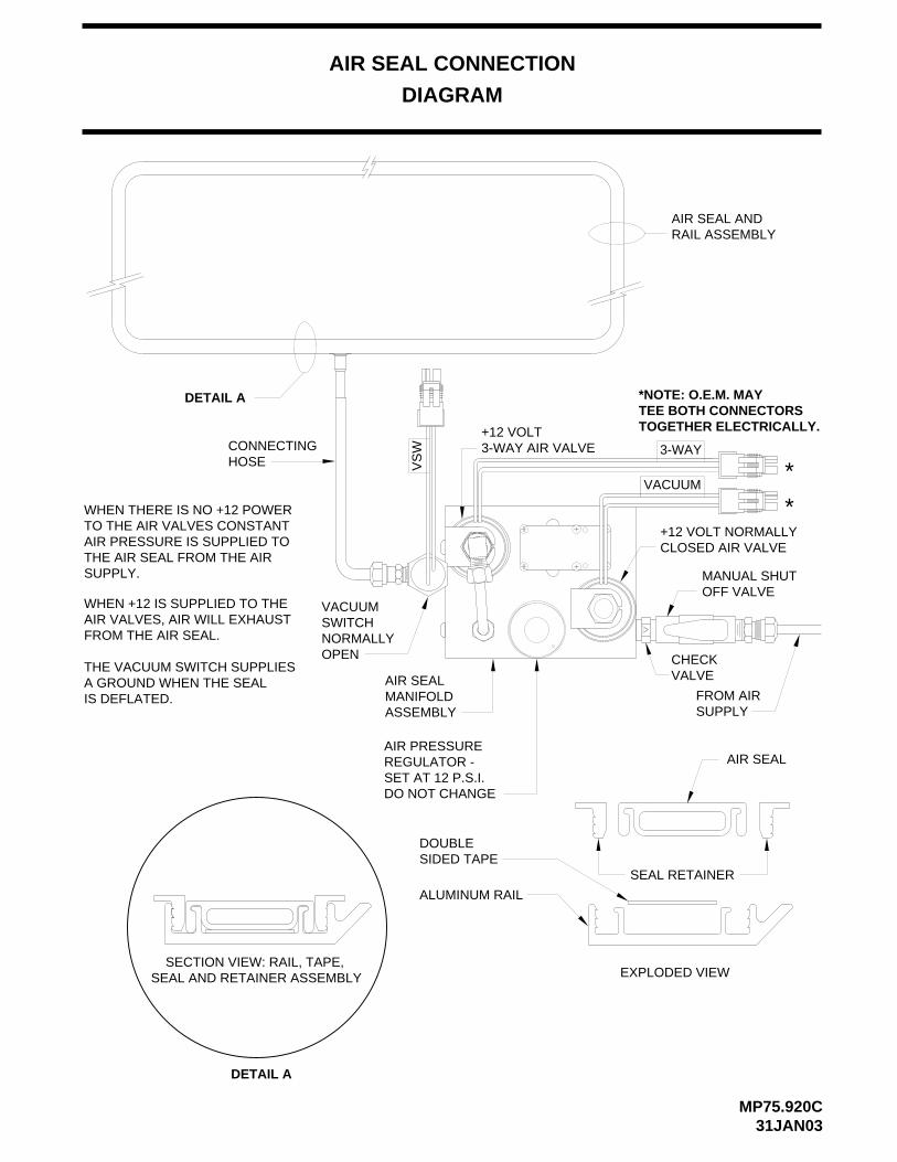
AIR SEAL CONNECTION
DIAGRAM
MP75.920C31JAN03
SECTION VIEW: RAIL, TAPE, SEAL AND RETAINER ASSEMBLY
SEAL RETAINER
AIR SEAL
EXPLODED VIEW
ALUMINUM RAIL
WHEN THERE IS NO +12 POWERTO THE AIR VALVES CONSTANTAIR PRESSURE IS SUPPLIED TOTHE AIR SEAL FROM THE AIRSUPPLY.
WHEN +12 IS SUPPLIED TO THEAIR VALVES, AIR WILL EXHAUSTFROM THE AIR SEAL.
DETAIL A
DETAIL A
AIR SEAL ANDRAIL ASSEMBLY
FROM AIRSUPPLY
AIR SEALMANIFOLDASSEMBLY
+12 VOLT 3-WAY AIR VALVECONNECTING
HOSE
AIR PRESSUREREGULATOR - SET AT 12 P.S.I.DO NOT CHANGE
CHECKVALVE
MANUAL SHUT OFF VALVE
+12 VOLT NORMALLYCLOSED AIR VALVE
*NOTE: O.E.M. MAYTEE BOTH CONNECTORS TOGETHER ELECTRICALLY.
VS
W 3-WAY
VACUUM*
*
IS DEFLATED.A GROUND WHEN THE SEALTHE VACUUM SWITCH SUPPLIES
NORMALLYSWITCHVACUUM
OPEN
SIDED TAPEDOUBLE
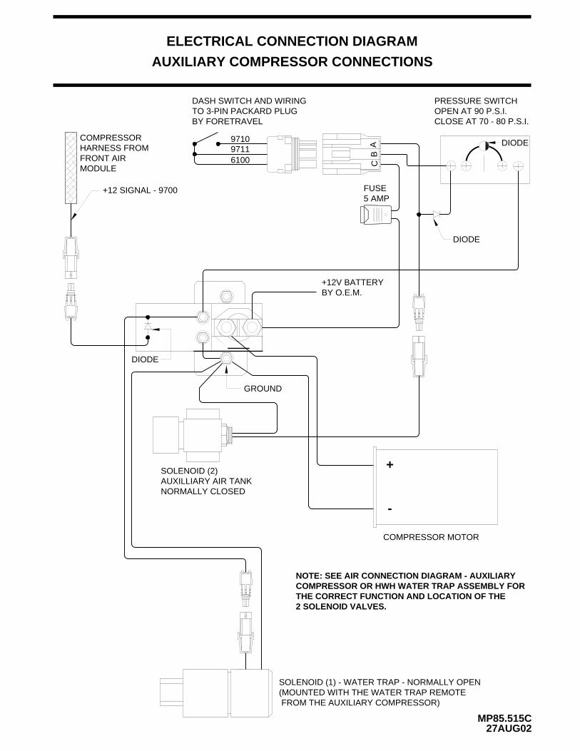
AUXILIARY COMPRESSOR CONNECTIONS
MP85.515C27AUG02
ELECTRICAL CONNECTION DIAGRAM
(MOUNTED WITH THE WATER TRAP REMOTE FROM THE AUXILIARY COMPRESSOR)
COMPRESSOR MOTOR
FUSE5 AMP
SOLENOID (1) - WATER TRAP - NORMALLY OPEN
CB
A
SOLENOID (2)AUXILLIARY AIR TANKNORMALLY CLOSED
+12 SIGNAL - 9700
COMPRESSORHARNESS FROMFRONT AIRMODULE
DASH SWITCH AND WIRING TO 3-PIN PACKARD PLUG BY FORETRAVEL
971097116100
CLOSE AT 70 - 80 P.S.I.OPEN AT 90 P.S.I.PRESSURE SWITCH
DIODE
DIODE
DIODE
GROUND
+12V BATTERYBY O.E.M.
NOTE: SEE AIR CONNECTION DIAGRAM - AUXILIARYCOMPRESSOR OR HWH WATER TRAP ASSEMBLY FOR THE CORRECT FUNCTION AND LOCATION OF THE
-
+
2 SOLENOID VALVES.
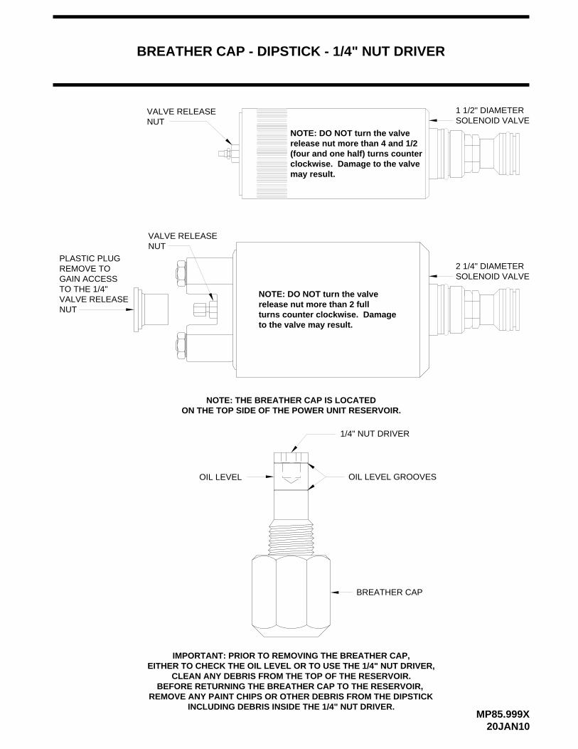
BREATHER CAP - DIPSTICK - 1/4" NUT DRIVER
MP85.999X20JAN10
VALVE RELEASE NUT
1 1/2" DIAMETERSOLENOID VALVE
NOTE: DO NOT turn the valverelease nut more than 4 and 1/2 (four and one half) turns counter clockwise. Damage to the valvemay result.
OIL LEVEL
BREATHER CAP
OIL LEVEL GROOVES
1/4" NUT DRIVER
NOTE: THE BREATHER CAP IS LOCATEDON THE TOP SIDE OF THE POWER UNIT RESERVOIR.
IMPORTANT: PRIOR TO REMOVING THE BREATHER CAP,EITHER TO CHECK THE OIL LEVEL OR TO USE THE 1/4" NUT DRIVER,
CLEAN ANY DEBRIS FROM THE TOP OF THE RESERVOIR.
INCLUDING DEBRIS INSIDE THE 1/4" NUT DRIVER.REMOVE ANY PAINT CHIPS OR OTHER DEBRIS FROM THE DIPSTICK
BEFORE RETURNING THE BREATHER CAP TO THE RESERVOIR,
VALVE RELEASE NUT
to the valve may result.turns counter clockwise. Damage
NOTE: DO NOT turn the valverelease nut more than 2 full
PLASTIC PLUGREMOVE TOGAIN ACCESSTO THE 1/4"VALVE RELEASENUT
SOLENOID VALVE2 1/4" DIAMETER