Embed Size (px)
Citation preview

Computerized Data Acquisition Systems
Chapter 4

Data Acquisition - Objectives
► State and discuss in terms a bright high school student would understand the following definitions related to data acquisition
bits, resolution, range, sampling frequency, ADC, DAC, multiplexing, single-ended input, differential input
► Convert between equivalent digital and analog values for 8, 10, and 12 bit analog-to-digital converters using offset binary notation

Data Acquisition - Objectives
►Describe the operation of common type of analog-to-digital converters
integratingsuccessive approximation
Use a LabView data acquisition module to simultaneously collect data from multiple sensors and write data to text file for off-line plotting and analysis

“Computerized” Data Acquisition Systems
►Almost exclusively talking about computerized systems.
►Non-computerized systems do existFew and far between
►Typically, at a minimum, data will be transferred to a computer for analysis and/or storage

Number Systems►Decimal numbers: base-10
941,356 =
Each digit can take one of 10 values: 0Each digit can take one of 10 values: 0--99

Binary Numbers
►Computers are constructed of massivearrays of “flip-flops”
►The output of a flip-flop can be _ or _►Collections of flip-flops can be used to store
(and manipulate) binary numbers►Binary: base-_: each digit can be one of two
values: _____

Binary Numbers
►101110102 = ?

Conversion from Decimal to Binary

Computer Interface Terminology► Bits: The number of digits in a binary number. A
1 bit binary number is either 0 or 1, a 2 bit binary number is either 00, 01, 10, or 11, etc. An N bit binary number can have 2N different values.
►Hex (or hexadecimal): Digital values expressed in base 16. Note that 1 hex digit is exactly 4 binary digits.
1AE16 = ? FF16= ?

Binary Numbers: Who Cares?
►“Sample” 0-5 V signals with your computer and convert the voltages to “3-bit” binary numbers:

Resolution affects Accuracy
From http://www.cyberresearch.com/cyb/cybtechtut.htm

Quantization of Signals
►Digitization of signals ⇒ ______________limitation
►Improved resolution achieved with higher bit counts:
Suppose you want < 1mV resolution on a 0-5 V signal. How many bits do you need to store all possible numbers?

Sampled-Data Systems
►Computers are event-driven systemsAddition, subtraction, multiplication, and division, all performed only at specific time intervalsClock-driven system: rising edges of the clock pulses are the events that drive/synchronize the operations of the computer. So…

Quantization and Sampling of Signals

Quantization and Sampling of Signals

Chapter 4 - Data Acquisition
From http://www.cyberresearch.com/cyb/cybtechtut.htm

Computer Interface Terminology►D/A converter (or DAC): Digital to Analog
converters are used to “map” a finite number of integer values onto a physical output range (usually a voltage)
►A/D converter (or ADC): Analog to Digital converters are used to convert continuous physical signals (usually voltages) into equivalent digital or binary numbers.

Computer Interface Terminology►Range: The difference between the upper (Vru)
and lower (Vrl) analog voltages that can be accurately converted to binary.
Common ranges are +5 volts (10 V range), 0 to +10 V (10 V range), and +10 volts (20 V range).
►Resolution: Amount of analog voltage equivalent to a single binary bit = (Vru -Vrl) / 2N
resolution of 12 bit A/D with a + 5 V range

D/A Converter► “R/2R ladder” used► closing switches gives
output voltages
S2 S1 S0 Vout1 0 0 4/8 Vin0 1 0 2/8 Vin0 0 1 1/8 Vin0 0 0 0
VVinin
VVoutout
2R2R
11 00 11 00 11S2S2 S1S1 S0S0
RR RR
2R2R 2R2R2R2R
00

Integrating / “Dual” Slope ADC► integrate input signal, Vin, for known period► then integrate known voltage, -Vref to zero
-
+
VI
CVin R
comparator
-
+-Vref
Control Logicand clock

Integrating / “Dual” Slope ADC
►integrate input signal, Vin for known period►integrate voltage (-Vref) for unknown period
VI
small Vin
large Vin
unknown period - proportional to Vinknown period
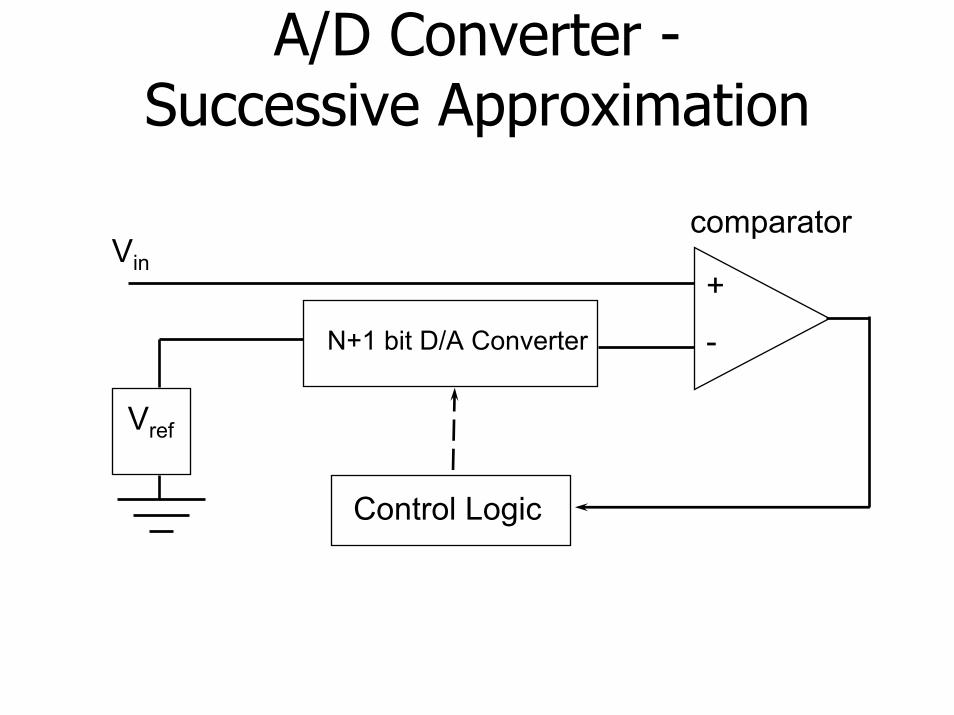
A/D Converter -Successive Approximation
comparatorVin
-
+
Vref
N+1 bit D/A Converter
Control Logic

A/D Converter -Successive Approximation
►DAC is used to sequentially “guess” bits N, N-1, N-2, … 1, 0 as 1’s
► output of D/A is compared to input voltage
keep current bit a 1 if Vin > VDAC►current approximation is lower than actual
set current bit to 0 if Vin < VDAC►current approximation is higher than actual
► all previously set bits are maintained as the next bit is “guessed” as a 1
Successive Approximation

Offset Binary 3 Bit A/D ConverterDigital (Binary) Output
10121002
0112
-5V -2.5V-3.75V -1.25V
+5V+2.5V+1.25V +3.75V
1112
0002
1102
Analog Voltage Input
0102
0012

ADC Formulas (p. 81)►Digital output from offset binary ADC:
►Nominal value of analog input:
=oD
=inV

Example #1►Given a 12 bit, + 5V ADC, what is the nominal
voltage for a digital value of 1000?
►What range of input voltages would all be converted to the digital value of 1000?
=nomV
=resolution

Example #2►Given a 10 bit, 0 to 10 V ADC, what is the nominal
voltage for a digital value of 763?
►What range of input voltages would all be converted to the digital value of 763?
=nomV
=resolution

Example #3►Given a 12 bit, +10V ADC, what digital value Do
would Vin= +5.623V convert to?
►Given an 8 bit, 0 to 5V ADC, what digital value Dowould Vin= 1.234V convert to?
=oD
=oD

Computer Interface Terminology
►Multiplexer : a switching" device to connect different analog signals to the same ADC
8 or 16 different analog inputs common, single-ended or differential inputs used, inputs often amplified near multiplexer

Computer Interface Terminology
►Single-Ended Inputs : All inputs use the same “ground”, so only 1 switch needed per signal
generally all signals must be of the same type
►Differential Inputs : Each input signal has its own separate “ground”, so two switches are required for each signal - one for signal and one for “common/ground.”

Single-Ended Multiplexer
All 16 inputs must have the same ground (common)
From http://www.cyberresearch.com/cyb/cybtechtut.htm

Differential Input Multiplexer
+
+
From http://www.cyberresearch.com/cyb/cybtechtut.htm
E0-
E7-
Must becarefulwith these
All 8 inputs can have different grounds (commons)


Typical DAQ
System
(inside computer)
Connect inputs here

National InstrumentsPCI-MIO-16E-4 Board
► 12 bit resolution (~2.4 mV/bit)► accuracy specs on manufacturer’s datasheet►+ 10 volts full scale input (bipolar)► offset binary coding► 8 channel differential input multiplexer►maximum single channel sampling rate of 500 kHz
(500,000 samples/sec)►maximum multi-channel sampling rate of
250 kHz (250,000 samples/sec)

Sources of Additional Info
►Analog Input/Output (from Omega Transactions Vol II)
►Tutorials and Applications Notes from National Instruments (www.ni.com)
►Go browse the web!