Embed Size (px)
Citation preview
Regd. Office England 2149641 20, Potters Lane, Kiln Farm, Milton Keynes, Buckinghamshire, MK11 3HF, U.K. www.cituk-online.com Tel: +44(01908) 260082 Fax: +44(01908) 260084 e-mail [email protected]
Supplier of the World’s Most Advanced Imaging, Digital Radiography, Enterprise Computer and Archive Systems
Computerised Information Technology
Case Application Note
Weld Inspection of 8 mm – 75 mm thickness with
Gamma Ir192 Radiation Isotope &
Digital Computed Radiography Technology This Case Application report describes the CR – Computed Radiographic Image Quality that meets the requirements of ASME Section VIII Division 1 (UW - 51 & UW – 52), Division 2 (Al-510 & AI-511), ASME Section 1 (PW - 51), ASME B31.1 (136.4.5), EN444 and EN1435 standards. This computed radiographic image quality is achieved by using an Ir192 radiation isotope. The radiographic image quality is assessed by measuring the contrast sensitivity and the radiographic resolution measured with the geometric unsharpness. The results measured are comparable to those achieved with conventional radiography.
Selection of radiographic technique and the radiation source depends on various factors such as: • The types of the material that you are inspecting • Thickness of the material • Types of defects, flaws • Radiographic sensitivity required by the referencing code, standards or specifications • The cost of radiography
Ir192 is one of the most important sources of energy for use in industrial γ-Radiography for Non Destructive Testing of metals. Due to its high-energy spectra, it is widely used for thick wall inspection (with CR one can inspect up to 100mms of material thickness). With Computed Radiography it has eliminated the requirement for Co60 radiation sources.
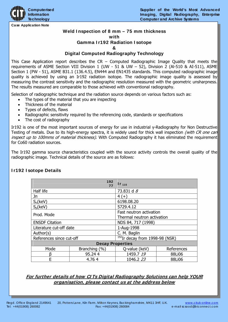
The Ir192 gamma source characteristics coupled with the source activity controls the overall quality of the radiographic image. Technical details of the source are as follows:
Ir192 Isotope Details
19277 Ir 115
Half life 73.831 d 8 Jπ 4 (+) Sπ(keV) 6198.08.20 Sp(keV) 5729.4.12
Prod. Mode Fast neutron activation Thermal neutron activation
ENSDF Citation NDS 84, 717 (1998) Literature cut-off date 1-Aug-1998 Author(s) C. M. Baglin References since cut-off 192Ir decay from 1998-98 (NSR)
Decay Properties Mode Branching (%) Q-value (keV) References β 95.24 4 1459.7 19 88Li06 E 4.76 4 1046.2 23 88Li06
For further details of how CITs Digital Radiography Solutions can help YOUR organisation, please contact us at the address below

Regd. Office England 2149641 20, Potters Lane, Kiln Farm, Milton Keynes, Buckinghamshire, MK11 3HF, U.K. www.cituk-online.com Tel: +44(01908) 260082 Fax: +44(01908) 260084 e-mail [email protected]
Supplier of the World’s Most Advanced Imaging, Digital Radiography, EnterpriseComputer and Archive Systems
Computerised Information Technology
Ir192 – Technical Data
Conventional Radiography
Computed Radiography
Gamma-radiation source, isotope Se-75, Ir-192 Se-75, Ir-192 T1/2 Se-75 T1/2 Ir-192
≈120 day ≈74 day
≈480 day ≈296 day
E, MeV (activity, to Ci) Se-75 Ir-192
≈0,215(120) ≈0,400 (120)
≈0,215(120) ≈0,400 (120)
Active core size, mm Se-75 Ir-192
To Ø 3x3 To Ø 4x4
To Ø 3x3 To Ø 4x4
Thickness of material exposure (Fe), mm. Se-75 Ir-192
5-30 10-60
5-70
10-120 Transportation and recharging Container (4 channels) Container (4 channels) Overall dimensions of the exposure head (mm)
300x130x270
300x130x270
Mass of exposure head (kg) ≈20 ≈20 Ir192 – Characteristics Radiographic Technique Setup
Thulium Tm-170
YtterbiumYb-169
SeleniumSe-75
Iridium Ir-192
Cobalt Co-60
Gamma energy (keV) 52-84 63-308 66-401 206-612 1173-1333
Half life (days) 128 32 120 74 1925
Gamma constant* 0.025 0.125 0.203 0.48 1.30 Source Output (radiation nominal dose at 1 meter) 160 µS/H
34 µS/H
130 µS/H
350 µS/H
ODD
Ir192 Radiation Isotope Device
SFD1000 mm
SOD975 mm
Weld Plate25 mm
Imaging Plate
Lead
Regd. Office England 2149641 20, Potters Lane, Kiln Farm, Milton Keynes, Buckinghamshire, MK11 3HF, U.K. www.cituk-online.com Tel: +44(01908) 260082 Fax: +44(01908) 260084 e-mail [email protected]
Supplier of the World’s Most Advanced Imaging, Digital Radiography, EnterpriseComputer and Archive Systems
Computerised Information Technology
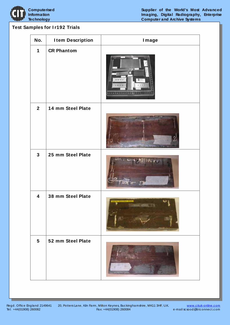
Test Samples for Ir192 Trials
No. Item Description Image
1 CR Phantom
2 14 mm Steel Plate
3 25 mm Steel Plate
4 38 mm Steel Plate
5 52 mm Steel Plate

Regd. Office England 2149641 20, Potters Lane, Kiln Farm, Milton Keynes, Buckinghamshire, MK11 3HF, U.K. www.cituk-online.com Tel: +44(01908) 260082 Fax: +44(01908) 260084 e-mail [email protected]
Supplier of the World’s Most Advanced Imaging, Digital Radiography, EnterpriseComputer and Archive Systems
Computerised Information Technology
Ir192 Results and Radiographic Image Mentioned below are the Results (with Radiographic Image and Exposure Parameters) of the Ir192 trials that have been carried out on different thickness of Steel Plate - Weld Samples and the CR Phantom. Note: The Radiographic Images displayed here are only for illustration purpose. The actual images are of high quality and contain more details. CR Phantom - Exposure Parameters & Radiograph Image
10mm Steel Plate - Exposure Parameters & Radiograph Image
Source Curie Strength
Exposure Time
SFD (Source to Film Distance)
Scanner Gain Filter Result - IQI
Ir192 15.8 45 1000 mm 600 125μm Pb 10th Line Pair
Source Curie Strength
Exposure Time
SFD (Source to Film Distance)
Scanner Gain Filter Result - IQI
Ir192 15.8 10M 10S 1000 mm 600 125μm Pb 10th wire on 10FE – 0.40 Diameter
Regd. Office England 2149641 20, Potters Lane, Kiln Farm, Milton Keynes, Buckinghamshire, MK11 3HF, U.K. www.cituk-online.com Tel: +44(01908) 260082 Fax: +44(01908) 260084 e-mail [email protected]
Supplier of the World’s Most Advanced Imaging, Digital Radiography, EnterpriseComputer and Archive Systems
Computerised Information Technology
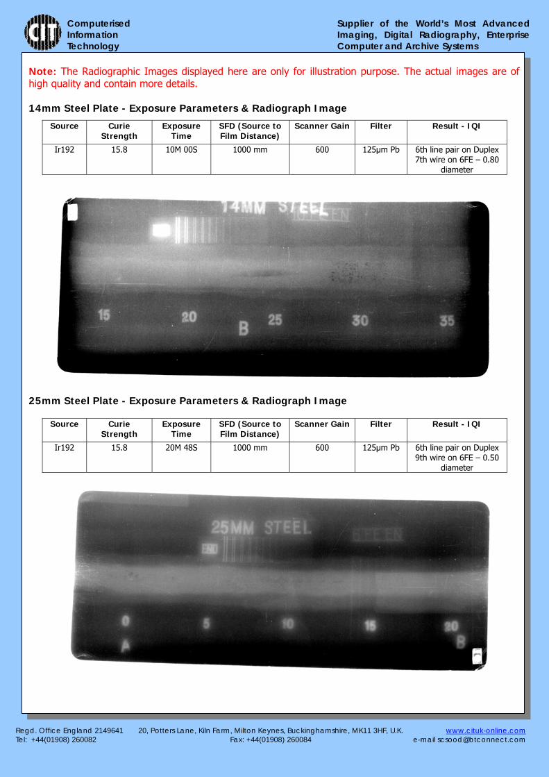
Note: The Radiographic Images displayed here are only for illustration purpose. The actual images are of high quality and contain more details. 14mm Steel Plate - Exposure Parameters & Radiograph Image
25mm Steel Plate - Exposure Parameters & Radiograph Image
Source Curie Strength
Exposure Time
SFD (Source to Film Distance)
Scanner Gain Filter Result - IQI
Ir192 15.8 10M 00S 1000 mm 600 125μm Pb 6th line pair on Duplex 7th wire on 6FE – 0.80
diameter
Source Curie Strength
Exposure Time
SFD (Source to Film Distance)
Scanner Gain Filter Result - IQI
Ir192 15.8 20M 48S 1000 mm 600 125μm Pb 6th line pair on Duplex 9th wire on 6FE – 0.50
diameter

Regd. Office England 2149641 20, Potters Lane, Kiln Farm, Milton Keynes, Buckinghamshire, MK11 3HF, U.K. www.cituk-online.com Tel: +44(01908) 260082 Fax: +44(01908) 260084 e-mail [email protected]
Supplier of the World’s Most Advanced Imaging, Digital Radiography, EnterpriseComputer and Archive Systems
Computerised Information Technology
Note: The Radiographic Images displayed here are only for illustration purpose. The actual images are of high quality and contain more details. 38mm Steel Plate - Exposure Parameters & Radiograph Image
52mm Steel Plate - Exposure Parameters & Radiograph Image
Source Curie Strength
Exposure Time
SFD (Source to Film Distance)
Scanner Gain Filter Result - IQI
Ir192 15.7 15M 20S 600 mm 600 125μm Pb 9th wire on 6FE – 0.50 diameter
9th wire on 1B11 – 0.51 Diameter
Source Curie Strength
Exposure Time
SFD (Source to Film
Distance)
Scanner Gain Filter Result - IQI
Ir192 15.7 32M 54S 600 mm 600 125μm Pb 6th wire on 1FE – 1.00 diameter
Regd. Office England 2149641 20, Potters Lane, Kiln Farm, Milton Keynes, Buckinghamshire, MK11 3HF, U.K. www.cituk-online.com Tel: +44(01908) 260082 Fax: +44(01908) 260084 e-mail [email protected]
Supplier of the World’s Most Advanced Imaging, Digital Radiography, EnterpriseComputer and Archive Systems
Computerised Information Technology
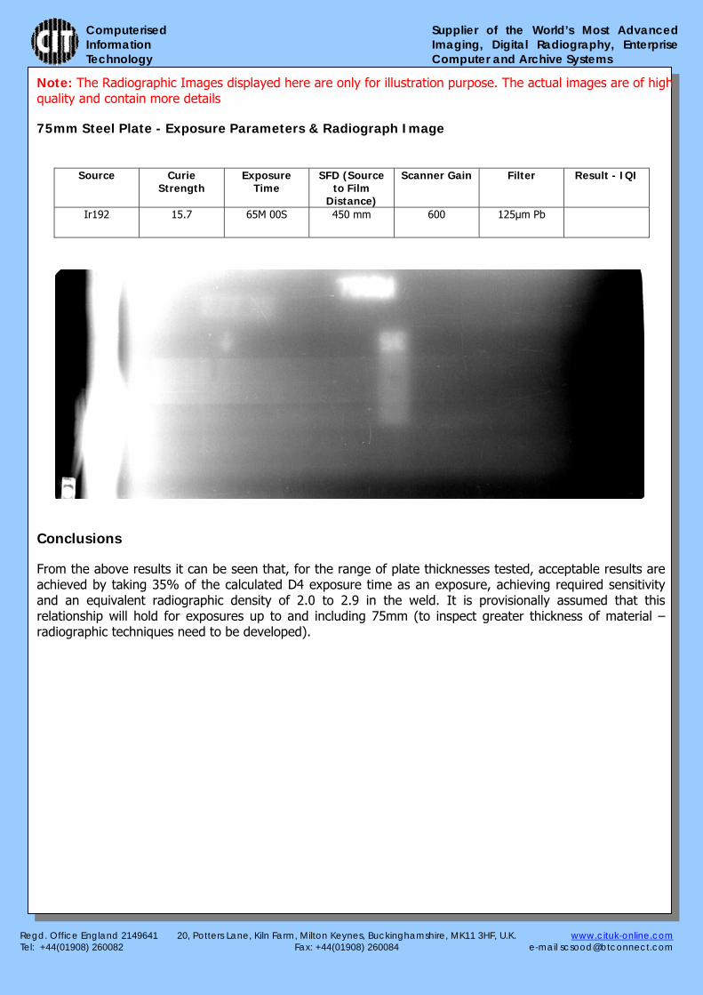
Note: The Radiographic Images displayed here are only for illustration purpose. The actual images are of high quality and contain more details
75mm Steel Plate - Exposure Parameters & Radiograph Image
Conclusions
From the above results it can be seen that, for the range of plate thicknesses tested, acceptable results are achieved by taking 35% of the calculated D4 exposure time as an exposure, achieving required sensitivity and an equivalent radiographic density of 2.0 to 2.9 in the weld. It is provisionally assumed that this relationship will hold for exposures up to and including 75mm (to inspect greater thickness of material – radiographic techniques need to be developed).
Source Curie Strength
Exposure Time
SFD (Source to Film
Distance)
Scanner Gain Filter Result - IQI
Ir192 15.7 65M 00S 450 mm 600 125μm Pb