Embed Size (px)
Citation preview
Computer Map· Proje
AVAILABILITY OF BOOKS AND MAPS OF THE U.S. GEOLOGICAL SURVEY
Instructions on ordering publications of the U.S. Geological Survey, along with prices of the last offerings, are given in the current-year issues of the monthly catalog "New Publications of the U.S. Geological Survey." Prices of available U.S. Geological Survey publications released prior to the current year are listed in the most recent annual "Price and Availability List" Publications that are listed in various U.S. Geological Survey catalogs (see back inside cover) but not listed in the most recent annual "Price and Availability List" are no longer available.
Prices of reports released to the open files are given in the listing "U.S. Geological Survey Open-File Reports," updated monthly, which is for sale in microfiche from the U.S. Geological Survey, Books and Open-File Reports Section, Federal Center, Box 25425, Denver, CO 80225. Reports released through the NTIS may be obtained by writing to the National Technical Information Service, U.S. Department of Commerce, Springfield, VA 22161; please include NTIS report number with inquiry.
Order U.S. Geological Survey publications by mail or over the counter from the offices given below.
BY MAIL
Books Professional Papers, Bulletins, Water-Supply Papers, Techniques
of Water-Resources Investigations, Circulars, publications of general interest (such as leaflets, pamphlets, booklets), single copies of Earthquakes & Volcanoes, Preliminary Determination of Epicenters, and some miscellaneous reports, including some of the foregoing series that have gone out of print at the Superintendent of Documents, are obtainable by mail from
U.S. Geological Survey, Books and Open-File Reports Federal Center, Box 25425
Denver, CO 80225
Subscriptions to periodicals (Earthquakes & Volcanoes and Preliminary Determination of Epicenters) can be obtained ONLY from the
Superintendent of Documents Government Printing OMce
Washington, D.C. 20402
(Check or money order must be payable to Superintendent of Documents.)
Maps
For maps, address mail orders to
U.S. Geological Survey, Map Distribution Federal Center, Box 25286
Denver, CO 80225
Residents of Alaska may order maps from
Alaska Distribution Section, U.S. Geological Survey, New Federal Building- Box 12
101 Twelfth Ave., Fairbanks, AK 99701
OVER THE COUNTER
Books Books of the U.S. Geological Survey are available over the
counter at the following Geological Survey Public Inquiries Offices, all of which are authorized agents of the Superintendent of Documents:
• WASHINGTON, D.C.--Main Interior Bldg., 2600 corridor, 18th and C Sts., NW.
• DENVER, Colorado--Federal Bldg., Rm. 169, 1961 Stout St. • LOS ANGELES, California--Federal Bldg., Rm. 7638, 300 N.
Los Angeles St. • MENLO PARK, California--Bldg. 3 (Stop 533), Rm. 3128,
345 Middlefield Rd. • RESTON, Vlrglnla--503 National Center, Rm. 1C402, 12201
Sunrise Valley Dr. • SALT LAKE CITY, Utah--Federal Bldg., Rm. 8105, 125
South State St. • SAN FRANCISCO, California--Customhouse, Rm. 504, 555
Battery St. • SPOKANE, Washington--U.S. Courthouse, Rm. 678, West
920 Riverside Ave .. • ANCHORAGE, Alaska--Rm. 101, 4230 University Dr. • ANCHORAGE, Alaska--Federal Bldg, Rm. E-146, 701 C St.
Maps
Maps may be purchased over the counter at the U.S. Geological Survey offices where books are sold (all addresses in above list) and at the following Geological Survey offices:
• ROLLA, Mlssourl--1400 Independence Rd. • DENVER, Colorado--Map Distribution, Bldg. 810, Federal
Center • FAIRBANKS, Alaska--New Federal Bldg., 101 Twelfth Ave.
Computer Programs for Common
Map Projections
By G. D. Newton
A contribution of the regional aquifer systems analysis program
Program Number: Equipment: Operating System: language:
None assigned PRIME 750
PRIMOS Rev 19.0 FORTRAN 77
U.S. GEOLOGICAL SURVEY BULLETIN 1642
DEPARTMENT OF THE INTERIOR
MANUEL LUJAN, JR., Secretary
U.S. GEOLOGICAL SURVEY
Dallas L. Peck, Director
first printing 1985 Second printing 1989
Any use of trade, product, or firm names in this publication is for descriptive purposes only and does not imply endorsement by the U.S. Government
UNITED STATES GOVERNMENT PRINTING OFFICE, WASHINGTON : 1989
For sale by the Books and Open-File Reports Section U.S. Geological Survey Federal Center, Box 25425 Denver, CO 80225
Library of Congress Cataloging-in-Publication Data
Newton, G.D. (Garth D.) Computer Programs for Common Map Projections
(U.S. Geological Survey Bulletin 1642) Bibliography Supt of Docs. no.: I 19.3:1642
1. Aquifers-Computer programs. 2. Map-projection-Computer programs. 3. FORTRAN (Computer program language). 4. Aquifers-Snake River (Wyo.-Wash.). I. National Regional Aquifer Systems Analysis Program (U.S.). I. Title. II. Series: United States Geological Survey Bulletin 1642. QE7S.B9 557.3 s 84-600386 [GB1199] [551.,49 1028 15425]
CONTENTS
Abstract 1 Introduction 1 Generating an ellipse of a spheroid 1 The American Polyconic projection 2 The Lambert Conformal Conic projection 3 The Universal Transverse Mercator projection 3 Computer program documentation 4
Subroutines for the American Polyconic map projection 4 Subroutines for the Lambert Conformal Conic map projection 4 Subroutines for the Universal Transverse Mercator map projection 5
Examples 6 Summary 6 References cited 6 Attachments 7
A. American Polyconic map projection source program listing, description of variables, and example execution 8
B. Lambert Conformal Conic map projection source program listing, description of variables, and example execution 15
C. Universal Transverse Mercator map projection source program listing, description of variables, and example execution 23
FIGURES 1-6. Diagrams showing:
TABLE
1. Elements of the generating ellipse of a spheroid 2 2. Elements of the American Polyconic projection 2 3. Secant cone for the Lambert Conformal Conic projection 3 4. The Universal Transverse Mercator projection 3 5. The rectangular coordinate system for the American Polyconic and the
Lambert Conformal Conic map projections 5 6. Universal Transverse Mercator coordinate system 6
1. Universal Transverse Mercator zone numbers with central and bounding meridians 4
III

Computer Programs for Common Map Projections
By G. D. Newton
Abstract
FORTRAN computer programs were originated to enable automated coordinate transformations between geodetic and rectangular coordinates within the American Polyconic, Lambert Conformal Conic, and Universal Transverse Mercator map projections. The programs facilitate' processing large quantities of point data for ground-water modeling and were developed for use in the Snake River Plain Regional Aquifer Systems Analysis study.
INTRODUCTION
This report is one in a series resulting from the U.S. Geological Survey's Snake River Plain RASA (Regional Aquifer Systems Analysis) study that began in 1979. The Snake River Plain study is one of a series of RASA studies made to evaluate the Nation's major aquifer systems. Each RASA study includes the development and use of digital computer ground-water flow models to aid in analysis.
Point data for the Snake River Plain RASA study are located by latitude and longitude coordinates and by the U.S. Bureau of Land Management's system of public lands subdivision. Data input to the computer inodels is based on a rectangular grid system. Nodal point values of parameter values are determined for each model grid cell from field data or as output from a computer model.
The U.S. Geological Survey, in cooperation with Idaho Department of Water Resources, determined irrigated areas on the Snake River Plain from Landsat imagery. The Landsat data consist of six scenes, each including 7.5 million pixe~s, or data points. A pixel represents about 4,452 m • Each pixel is located by latitude and longitude and is assigned a numerical value that indicates whether the land is irrigated or nonirrigated. Total irrigated area for each model grid cell thus can be determined. Because of the large number of data points, manual methods of determining irrigated acreage for each model grid cell from the pixel data were impractical for the RASA study. Therefore, an automated method was developed using the programs documented in this report. Other large data sets, such as ground-water levels, specific capacities, irrigation diversions, and ground-water pumping, also can be processed more easily by automated methods.
The purpose of this study was to develop a set of computer programs to convert geodetic coordinates
from rectangular map coordinates for commonly used maps. FORTRAN programs were developed for common map projections: American Polyconic, Lambert Conformal Conic, and Universal Transverse Mercator. Both forward and inverse computations were included.
GENERATING AN ELLIPSE OF A SPHEROID
A map projection is a planar representation of the curved surface of the Earth. Imposed upon the Earth's surface is a geodetic coordinate system of latitude,cf>, and longitude,X.
A map projection is defined as a systematic method of drawing lines on a planar surface. Exact representation of the surface is impossible, but errors can be minimized, depending on the intended use of the map. Scale and shape are the fundamental considerations.
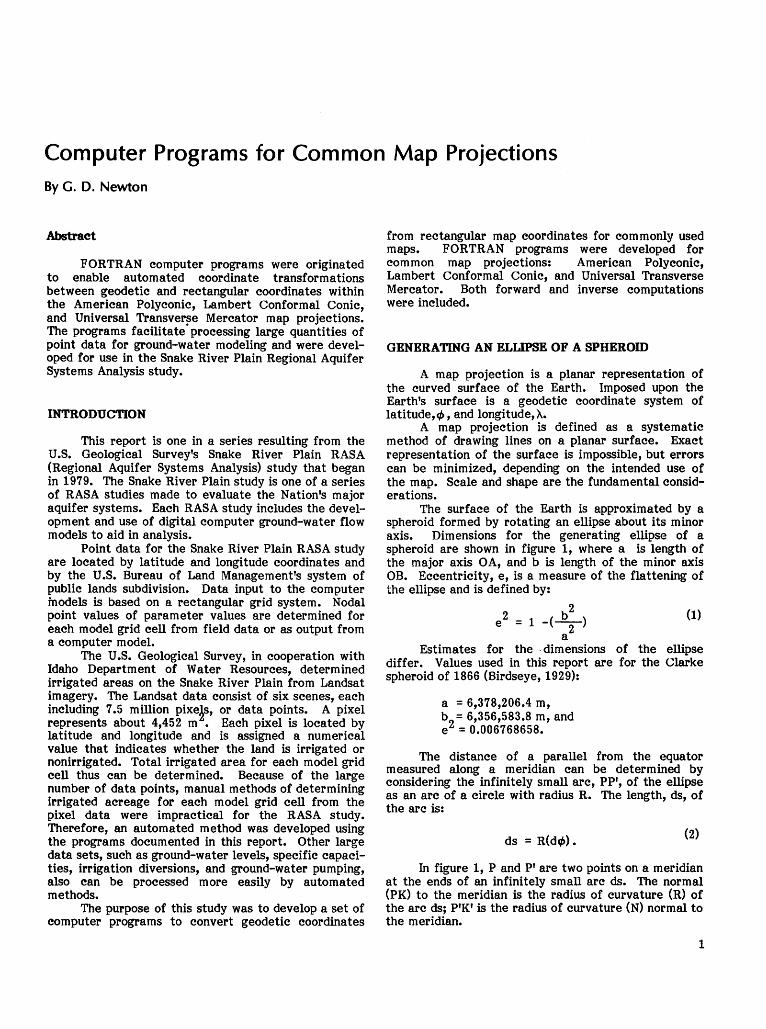
The surface of the Earth is approximated by a spheroid formed by rotating an ellipse about its minor axis. Dimensions for the generating ellipse of a spheroid are shown in figure 1, where a is length of the major axis OA, and b is length of the minor axis OB. Eccentricity, e, is a measure of the flattening of the ellipse and is defined by:
e2 = 1 -(£) (1) 2 a
Estimates for the ·dimensions of the ellipse differ. Values used in this report are for the Clarke spheroid of 1866 (Birdseye, 1929):
a = 6,378,206.4 m, b
2 = 6,356,583.8 m, and
e = 0.006768658.
The distance of a parallel from the equator measured along a meridian can be determined by considering the infinitely small arc, PP', of the ellipse as an arc of a circle with radius R. The length, ds, of the arc is:
ds = R(df/>). (2)
In figure 1, P and P' are two points on a meridian at the ends of an infinitely small arc ds. The normal (PK) to the meridian is the radius of curvature (R) of the arc ds; P'K' is the radius of curvature (N) normal to the meridian.
1
The lengths R and N can be computed for any latitude by:
R = a(1-e2 )/[1-e2 sin2 (~)] 3 12 ,
N = a/[1-e2sin2(<1')] 112
{3)
(4)
The distance from the equator S is the integral of ds from zero to the latitude,tf>. The integral is approximated by the following series:
S = ~+ ~ sin (2'~J + ; sin (4~) (5)
A4 . As + ~ s1n (6¢) +~sin (8~) + •••
The distance between any two parallels, ¢1
and ¢
2 on the meridian is:
S=Af-~cos(2ci>)sin(Acf>)
+~cos(4¢)sin(~¢) -(6)
where
¢=(ct>1+ ¢2)/2(radians),
A¢=(ct>2- ¢1)'
THB AMERICAN POLYCONIC PROJECTION
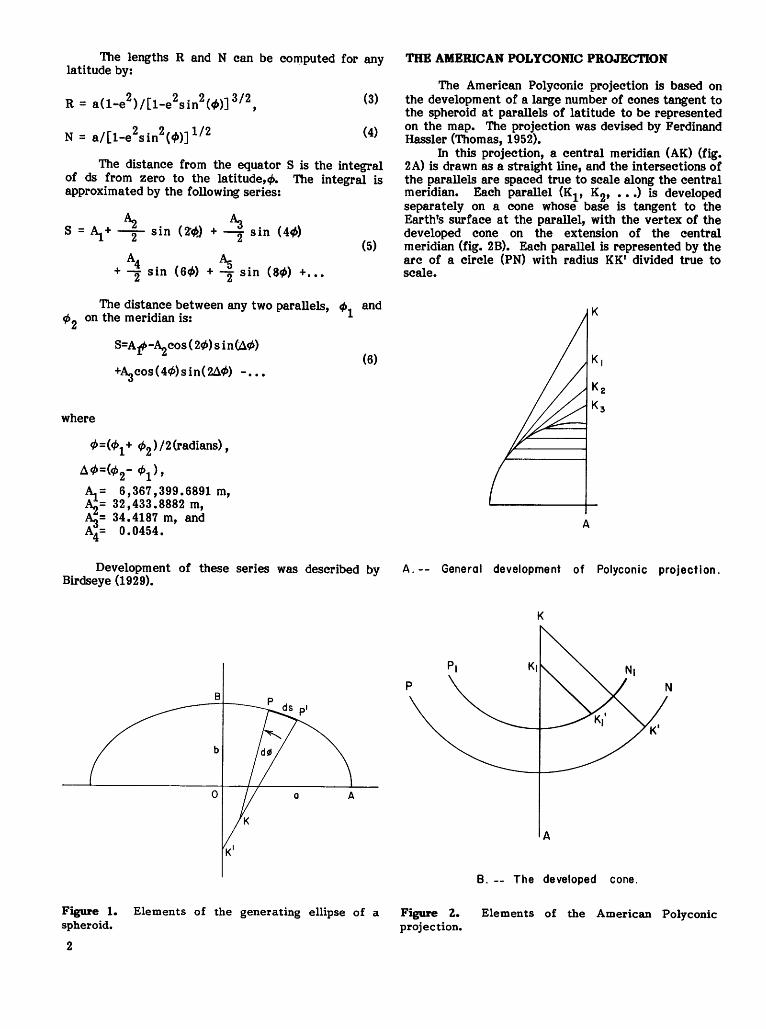
The American Polyconic projection is based on the development of a large number of cones tangent to the spheroid at parallels of latitude to be represented on the map. The projection was devised by Ferdinand Hassler (Thomas, 1952).
In this projection, a central meridian (AK) (fig. 2A) is drawn as a straight line, and the intersections of the parallels are spaced true to scale along the central meridian. Each parallel (Kl' K2, ••• ) is developed separately on a cone whose base is tangent to the Earth's surface at the parallel, with the vertex of the developed cone on the extension of the central meridian (fig. 2B). Each parallel is represented by the arc of a circle (PN) with radius KK' divided true to scale.
K
~= 6,367,399.6891 m, ~= 32,433.8882 m, ~= 34.4187 m, and A A4= 0.0454.
Development of these series was described by A.-- General development of Polyconic projection. Birdseye (1929).
A
Figure 1. Elements of the generating ellipse of a spheroid.
2
K
A
B. -- The developed cone.
Figure 2.. Elements of the American Polyconic projection.
The central meridian is a straight line and all other meridians are curves. The intersections of meridians and parallels are not at right angles except at the central meridian.
Errors in the meridian distances, areas, shapes, and angles of graticule (intersection of longitude and latitude) increase with the longitudinal limits of the polyconic projection and restrict its usage to largescale maps. However, the polyconic projection is simple to construct with little distortion of areas, shapes, distances, and azimuths for small areas at large scales. Mathematical development of the projection is described by Birdseye (1929).
THE LAMBERT CONFORMAL CONIC PROJECTION
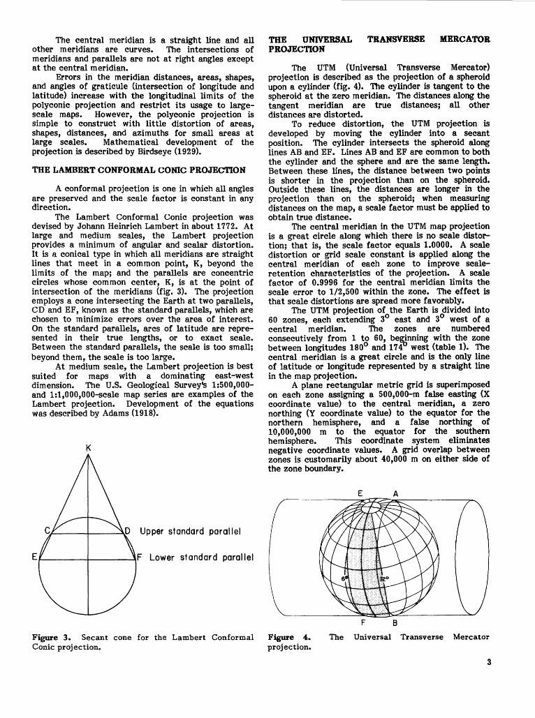
A conformal projection is one in which all angles are preserved and the scale factor is constant in any direction.
The Lambert Conformal Conic projection was devised by Johann Heinrich Lambert in about 1772. At large and medium scales, the Lambert projection provides a minimum of angular and scalar distortion. It is a conical type in which all meridians are straight lines that meet in a common point, K, beyond the limits of the map; and the parallels are concentric circles whose common center, K, is at the point of intersection of the meridians (fig. 3). The projection employs a cone intersecting the Earth at two parallels, CD and EF, known as the standard parallels, which are chosen to minimize errors over the area of interest. On the standard parallels, arcs of latitude are represented in their true lengths, or to exact scale. Between the standard parallels, the scale is too small; beyond them, the scale is too large.
At medium scale, the Lambert projection is best suited for maps with a dominating east-west dimension. The U.S. Geological Survey's 1:500,000-and 1:1,000,000-scale map series are examples of the Lambert projection. Development of the equations was described by Adams (1918).
K
Upper standard parallel
Figure 3. Secant cone for the Lambert Conformal Conic projection.
THE UNIVERSAL TRANSVERSE MERCATOR PROJECTION
The UTM (Universal Transverse Mercator) projection is described as the projection of a spheroid upon a cylinder (fig. 4). The cylinder is tangent to the spheroid at the zero meridian. The distances along the tangent meridian are true distances; all other distances are distorted.
To reduce distortion, the UTM projection is developed by moving the cylinder into a secant position. The cylinder intersects the spheroid along lines AB and EF. Lines AB and EF are common to both the cylinder and the sphere and are the same length. Between these lines, the distance between two points is shorter in the projection than on the spheroid. Outside these lines, the distances are longer in the projection than on the spheroid; when measuring distances on the map, a scale factor must be applied to obtain true distance.
The central meridian in the UTM map projection is a great circle along which there is no scale distortion; that is, the scale factor equals 1.0000. A scale distortion or grid scale constant is applied along the central meridian of each zone to improve scaleretention characteristics of the projection. A scale factor of 0.9996 for the central meridian limits the scale error to 1/2,500 within the zone. The effect is that scale distortions are spread more favorably.
The UTM projection of the Earth is divided into 60 zones, each extending 3° east and 3° west of a central meridian. The zones are numbered consecutively from 1 to 60, beginning with the zone between longitudes 180° and 174° west (table 1). The central meridian is a great circle and is the only line of latitude or longitude represented by a straight line in the map projection.
A plane rectangular metric grid is superimposed on each zone assigning a 500,000-m false easting (X coordinate value) to the central meridian, a zero northing (Y coordinate value) to the equator for the northern hemisphere, and a false northing of 10,000,000 m to the equator for the southern hemisphere. This coordinate system eliminates negative coordinate values. A grid overlap between zones is customarily about 40,000 m on either side of the zone boundary.
Figure 4. projection.
E A
F B The Universal Transverse Mercator
3
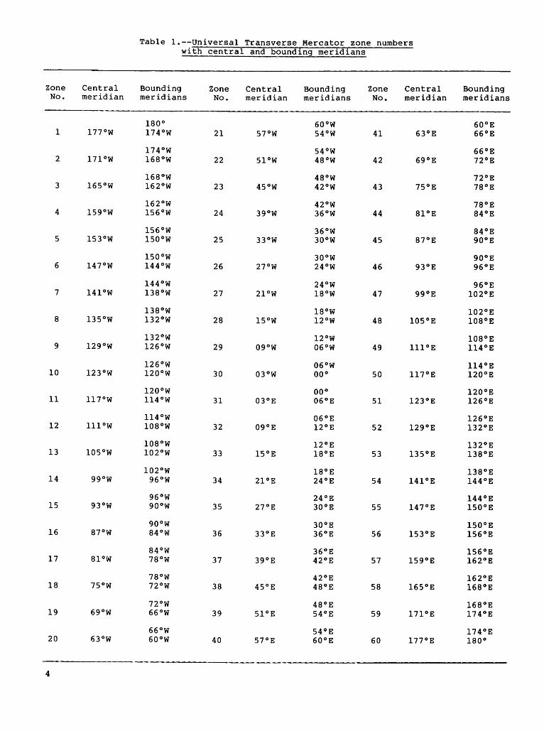
Table I.--Universal Transverse Mercator zone numbers with central and boundin9 meridians
Zone Central Bounding Zone Central Bounding Zone Central Bounding No. meridian meridians No. meridian meridians No. meridian meridians
180° 60°W 60°E 1 177°W 174°W 21 57°W 54°W 41 63°E 66°E
174°W 54°W 66°E 2 171°W 168°W 22 51°W 48°W 42 69°E 72°E
168°W 48°W 72°E 3 165°W 162°W 23 45°W 42°W 43 75°E 78°E
162°W 42°W 78°E 4 159°W 156°W 24 39°W 36°W 44 81°E 84°E
156°W 36°W 84°E 5 153°W 150°W 25 33°W 30°W 45 87°E 90°E
150°W 30°W 90°E 6 147°W 144°W 26 27°W 24°W 46 93°E 96°E
144°W 24°W 96°E 7 141°W 138°W 27 21°W l8°W 47 ggoE 102°E
138°W l8°W 102°E 8 135°W 132°W 28 l5°W l2°W 48 105°E 108°E
132°W l2°W 108°E 9 129°W 126°W 29 09°W 06°W 49 lll 0 E ll4°E
126°W 06°W ll4°E 10 123°W 120°W 30 03°W 00° 50 ll7°E 120°E
120°W 00° 120°E 11 ll7°W ll4°W 31 03°E 06°E 51 123°E 126°E
ll4°W 06°E 126°E 12 lll 0 W 108°W 32 09°E l2°E 52 129°E 132°E
108°W l2°E 132°E 13 105°W 102°W 33 l5°E l8°E 53 135°E 138°E
102°W l8°E 138°E 14 ggow 96°W 34 21°E 24°E 54 141°E 144°E
96°W 24°E 144°E 15 93°W 90°W 35 27°E 30°E 55 147°E 150°E
90°W 30°E 150°E 16 87°W 84°W 36 33°E 36°E 56 153°E 156°E
84°W 36°E 156°E 17 8l 0 W 78°W 37 39°E 42°E 57 159°E 162°E
78°W 42°E 162°E 18 75°W 72°W 38 45°E 48°E 58 165°E 168°E
72°W 48°E 168°E 19 69°W 66°W 39 51°E 54°E 59 171°E 174°E
66°W 54°E 174°E 20 63°W 60°W 40 57°E 60°E 60 177°E 180°
4

The UTM system was developed for the military to satisfy the following requirements (U.s. Department of the Army, 1951) for a worldwide plane coordinate system:
(1) Directional errors must be minimized. (2) There must be "continuity" over sizeable areas
with a minimum number of zones (3) Scale errors caused by the projection must not
exceed a specified tolerance. (4) A plane rectangular system of coordinates must
have unique referencing for all zones. (5) Transformation formulas from one zone to another
must be uniform throughout the system. (6) Meridiana! convergence must not exceed 5°.
The UTM system is used between latitudes of 84° N. and 80° S. The polar regions are covered by the Universal Polar Stereographic System, which complements the UTM system but is independent of it. An overlap occurs along the boundary of the two systems.
COMPUTER PROGRAM DOCUMENTATION
Programs in ~is report are written in FORTRAN 77 for PRIME 750 computer systems. Some minor modifications may be necessary for other systems. The programs use double precision throughout. On other computers and for some applications on PRIME systems, double precision variables may not be necessary to achieve the desired accuracy.
Three sets of example runs are provided, one for each of the three map projections presented in this report. Each set will compute rectangular coordinates from latitude and longitude, as well as the inverse.
FORTRAN computer listings and an explanation of the variables for the American Polyconic, Lambert Conformal Conic, and UTM map projections are given in the attachments. An explanation of the variable names and the subroutines also is given in the attachments.
Subroutines for the American Polyconic Map Projection
Three subroutines for the American Polyconic map projection are called by the user:
CALL DATA (BASLAT,BASLON) CALL XYTRAN (LAT, LON, X, Y) (forward transformation) CALL INVERSE (LAT, LON, X,Y) (inverse transformation)
BASLAT is the latitude of the or1gm (0) and BASLON is the longitude of the origin (fig. 5). LAT and LON are the latitude and longitude, in decimal degrees, of the point (P) to be located; X andY are the rectangular coordinates, in meters. The origin should be located on the central meridian, which is theoretically the only straight line on the map.
1use of brand names in this report is for identification purposes only and does not constitute endorsement by the U.s. Geological Survey.
Subroutine DATA must be called first. It initializes basic parameters.
Subroutine XYTRAN determines the rectangular coordinates, in meters, for a point, given the latitude and longitude of the point (BASLAT, BASLON).
Subroutine INVERSE determines the geodetic coordinates from the rectangular coordinates, in meters. All geodetic coordinates are in decimal deg-rees.
The calculation of the inverse is an iterative process. The number of iterations required depends on the desired accuracy. Double precision variables may be necessary on some computers.
Subroutines for the Lambert Conformal Conic Map Projection
Three subroutines for the Lambert Conformal Conic map projection are called by the user:
CALL DATA (BASLAT, BASLON) CALL XYTRAN (LAT, LON, X,Y) (forward transformation) CALL INVERSE (LAT, LON, X, Y) (inverse transformation)
The subroutine DATA must be called first. It initializes the basic parameters. The standard parallels are set to 45° N. and 33° N. These values may be changed in subroutine DATA.
BASLAT is the latitude of the origin (0) and BASLON is the longitude of the origin (fig. 5). LAT and LON are the latitude and longitude, in decimal degrees, of the point (P) to be located; X and Y are the rectangular coordinates, in meters, from the origin.
Subroutine XYTRAN determines the rectangular coordinates, in meters, from point (BASLAT, BASLON) for the latitude and longitude of a point.
y
~ ~ y &:::: -------
~
z 0 _j CJ) <( CD BASLAT
------------------+-----------~X~------- X 0
Figure 5. The rectangular coordinate system for the American Polyconic and the Lambert Conformal Conic map projections.
5
Subroutine INVERSE is an iterative routine that determines the geographical coordinates from the rectangular coordinates, in meters. All geographical coordinates are in decimal degrees.
Any meridian can be used as the Y axis for the rectangular coordinate system because all meridians are represented as straight lines.
Subroutines for the Universal Transverse Mercator Map Projection
Three subroutines for the UTM map projection are called by the user:
CALL DATA (BASLAT, LAM) CALL UTMF (LAT, LON, X, Y) (forward transformation) CALL AUTMI (LAT, LON, X, Y) (inverse transformation)
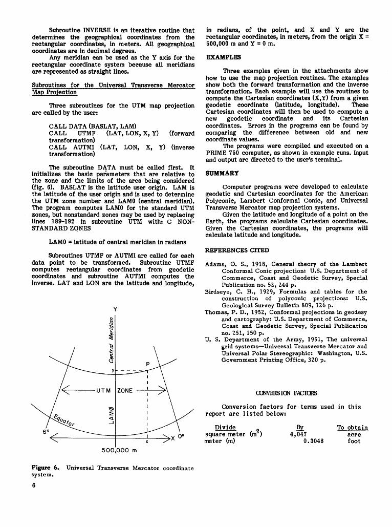
The subroutine DATA must be called first. It initializes the basic parameters that are relative to the zone and the limits of the area being considered (fig. 6). BASLAT is the latitude user origin. LAM is the latitude of the user origin and is used to determine the UTM zone number and LAMO (central meridian). The program computes LAMO for the standard UTM zones, but nonstandard zones may be used by replacing lines 189-192 in subroutine UTM with: c NONSTANDARD ZONES
LAMO =latitude of central meridian in radians
Subroutines UTMF or AUTMI are called for each data point to be transformed. Subroutine UTMF computes rectangular coordinates from geodetic coordinates and subroutine AUTMI computes the inverse. LAT and LON are the latitude and longitude,
y
500,000 m
Figure 6. Universal Transverse Mercator coordinate system.
6
in radians, of the point, and X and Y are the rectangular coordinates, in meters, from the origin X= 500,000 m and Y = 0 m.
EXAMPLES
Three examples given in the attachments show how to use the map projection routines. The examples show both the forward transformation and the inverse transformation. Each example will use the routines to compute the Cartesian coordinates (X, Y) from a given geodetic coordinate (latitude, longitude). These Cartesian coordinates will then be used to compute a new geodetic coordinate and its cartesian coordinates. Errors in the programs can be found by comparing the difference between old and new coordinate values.
The programs were compiled and executed on a PRIME 750 computer, as shown in example runs. Input and output are directed to the user's terminal.
SUMMARY
Computer programs were developed to calculate geodetic and Cartesian coordinates for the American Polyconic, Lambert Conformal Conic, and Universal Transverse Mercator map projection systems.
Given the latitude and longitude of a point on the Earth, the programs calculate Cartesian coordinates. Given the Cartesian coordinates, the programs will calculate latitude and longitude.
REFERENCES CITED
Adams, 0. S., 1918, General theory of the Lambert Conformal Conic projection: U.S. Department of Commerce, Coast and Geodetic Survey, Special Publication no. 52, 2.44 p.
Birdseye, C. H., 192.9, Formulas and tables for the construction of polyconic projections: U.S. Geological Survey Bulletin 809, 12.6 p.
Thomas, P. D., 1952., Conformal projections in geodesy and cartography: U.S. Department of Commerce, Coast and Geodetic Survey, Special Publication no. 2.51, 150 p.
U. S. Department of the Army, 1951, The universal grid systems-Universal Transverse Mercator and Universal Polar Stereographic: Washington, U.S. Government Printing Office, 32.0 p.
COnversion factors for tenns used in this report are listed below:
Divide square meter (m2) meter (m)
~ 4,047
0.3048
To obtain acre foot
Attachments A - C
7
8
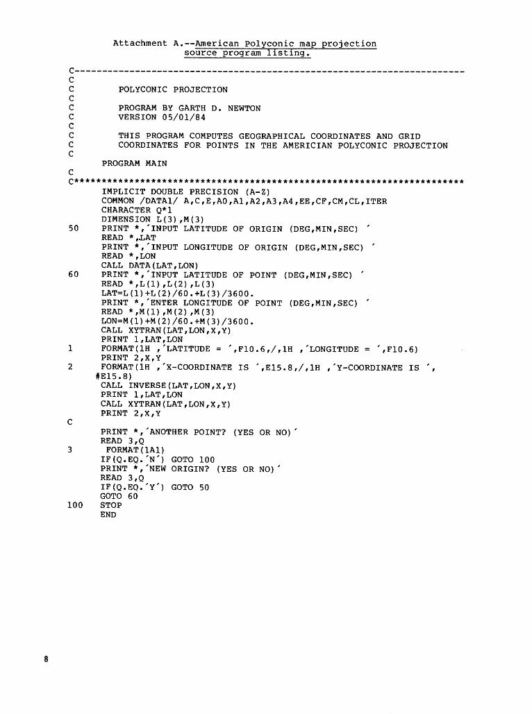
Attachment A.--American Polyconic map projection source program l1st1ng.
c-----------------------------------------------------------------------c c c c c c c c c
c
POLYCONIC PROJECTION
PROGRAM BY GARTH D. NEWTON VERSION 05/01/84
THIS PROGRAM COMPUTES GEOGRAPHICAL COORDINATES AND GRID COORDINATES FOR POINTS IN THE AMERICIAN POLYCONIC PROJECTION
PROGRAM MAIN
C*********************************************************************** IMPLICIT DOUBLE PRECISION (A-Z) COMMON /DATAl/ A,C,E,AO,Al,A2,A3,A4,EE,CF,CM,CL,ITER CHARACTER Q*l DIMENSION L(3) ,M(3)
50 PRINT *,'INPUT LATITUDE OF ORIGIN (DEG,MIN,SEC) ' READ * ,.LAT PRINT *,'INPUT LONGITUDE OF ORIGIN (DEG,MIN,SEC) ' READ *,LON CALL DATA(LAT,LON)
60 PRINT *,'INPUT LATITUDE OF POINT (DEG,MIN,SEC) ' READ * , L ( 1 ) , L ( 2 ) , L ( 3 ) LAT=L(l)+L(2)/60.+L(3)/3600. PRINT *,'ENTER LONGITUDE OF POINT (DEG,MIN,SEC) ' READ * , M ( 1) , M ( 2) , M ( 3) ·LON=M ( 1) +M ( 2) I 6 0 • +M ( 3) I 3 6 0 0 • CALL XYTRAN(LAT,LON,X,Y) PRINT l,LAT,LON
1 FORMAT(lH ,'LATITUDE= ',Fl0.6,/,1H ,'LONGITUDE= ',Fl0.6) PRINT 2,X,Y
2 FORMAT(lH ,'X-COORDINATE IS ',El5.8,/,1H ,'Y-COORDINATE IS '
c
#El5.8) CALL INVERSE(LAT,LON,X,Y) PRINT l,LAT,LON CALL XYTRAN(LAT,LON,X,Y) PRINT 2,X,Y
PRINT *,'ANOTHER POINT? (YES OR NO)' READ 3 ,Q
3 FORMAT(lAl) IF(Q.EQ.'N') GOTO 100 PRINT *,'NEW ORIGIN? (YES OR NO)' READ 3 ,Q IF(Q.EQ.'Y') GOTO 50 GOTO 60
100 STOP END
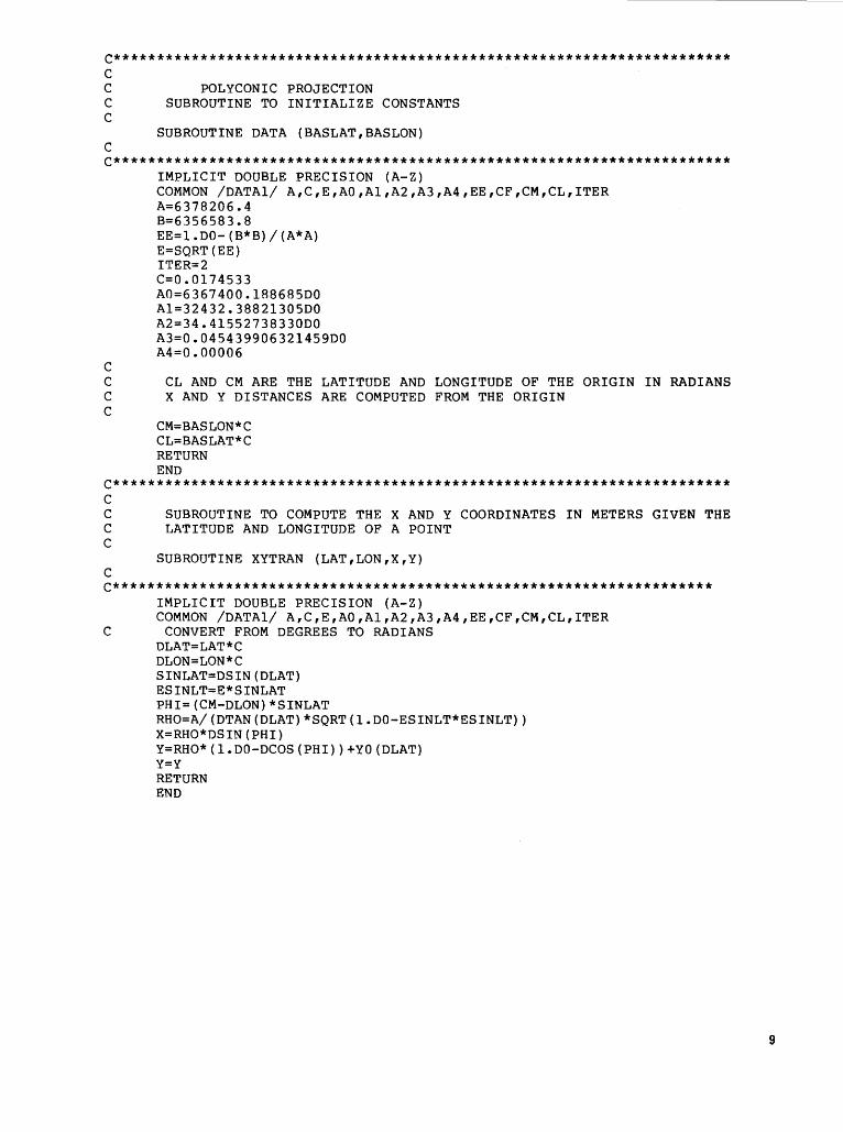
C*********************************************************************** c c c c
c
POLYCONIC PROJECTION SUBROUTINE TO INITIALIZE CONSTANTS
SUBROUTINE DATA (BASLAT,BASLON)
C*********************************************************************** IMPLICIT DOUBLE PRECISION (A-Z)
c
COMMON /DATAl/ A,C,E,AO,Al,A2,A3,A4,EE,CF,CM,CL,ITER A=6378206.4 B=6356583.8 EE=l.DO-(B*B)/(A*A) E=SQRT(EE) ITER=2 C=O.Ol74533 A0=6367400.188685DO Al=32432.38821305DO A2=34.41552738330DO A3=0.045439906321459DO A4=0.00006
C CL AND CM ARE THE LATITUDE AND LONGITUDE OF THE ORIGIN IN RADIANS C X AND Y DISTANCES ARE COMPUTED FROM THE ORIGIN c
CM=BASLON*C CL=BASLAT*C RETURN END
C*********************************************************************** c c c c
c
SUBROUTINE TO COMPUTE THE X AND Y COORDINATES IN METERS GIVEN THE LATITUDE AND LONGITUDE OF A POINT
SUBROUTINE XYTRAN (LAT,LON,X,Y)
C********************************************************************* IMPLICIT DOUBLE PRECISION (A-Z) COMMON /DATAl/ A,C,E,AO,Al,A2,A3,A4,EE,CF,CM,CL,ITER
C CONVERT FROM DEGREES TO RADIANS OLAT=LAT*C DLON=LON*C SINLAT=DSIN(DLAT) ESINLT=E*SINLAT PHI=(CM-DLON)*SINLAT RHO=A/(DTAN(DLAT)*SQRT(l.DO-ESINLT*ESINLT)) X=RHO*DSIN(PHI) Y=RHO*(l.DO-DCOS(PHI))+YO(DLAT) Y=Y RETURN END
9
10
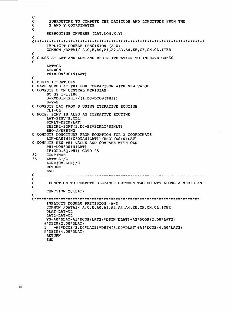
c C SUBROUTINE TO COMPUTE THE LATITUDE AND LONGITUDE FROM THE C X AND Y COORDINATES c
SUBROUTINE INVERSE (LAT,LON,X,Y) c C***********************************************************************
IMPLICIT DOUBLE PRECISION (A-Z) COMMON /DATAl/ A,C,E,AO,Al,A2,A3,A4,EE,CF,CM,CL,ITER
c C GUESS AT LAT AND LON AND BEGIN ITERATION TO IMPROVE GUESS c
c
LAT=CL LON=CM PHI=LON*DSIN(LAT)
C BEGIN ITERATIONS C SAVE GUESS AT PHI FOR COMPARISON WITH NEW VALUE C COMPUTE S.ON CENTRAL MERIDIAN
DO 32 I=l,lOO S=X*DSIN(PHI)/(l.DO+DCOS(PHI)) S=Y-S
C COMPUTE LAT FROM S USING ITERATIVE ROUTINE CLl=CL
C NOTE: SINV IS ALSO AN ITERATIVE ROUTINE LAT=SINV(S,CLl) SINLT=DSIN(LAT) EESIN2=SQRT(l.DO-EE*SINLT*SINLT) RHO=A/EESIN2
C COMPUTE LONGITUDE FROM EQUATION FOR X COORDINATE LON=DASIN((X*DTAN(LAT))/RHO)/DSIN(LAT)
C COMPUTE NEW PHI VALUE AND COMPARE WITH OLD PHI=LON*DSIN(LAT) IF(OLD.EQ.PHI) GOTO 35
32 CONTINUE 35 LAT=LAT/C
LON=(CM-LON)/C RETURN END
c-----------------------------------------------------------------------c C FUNCTION TO COMPUTE DISTANCE BETWEEN TWO POINTS ALONG A MERIDIAN c
FUNCTION YO(LAT) c C*********************************************************************
IMPLICIT DOUBLE PRECISION (A-Z) COMMON /DATAl/ A,C,E,AO,Al,A2,A3,A4,EE,CF,CM,CL,ITER DLAT=LAT-CL LAT2=LAT+CL YO=AO*DLAT-Al*DCOS(LAT2)*DSIN(DLAT)+A2*DCOS(2.DO*LAT2)
i*DSIN(2.DO*DLAT) 1 -A3*DCOS(3.DO*LAT2)*DSIN(3.DO*DLAT)+A4*DCOS(4.DO*LAT2) i*DSIN(4.DO*DLAT)
RETURN END
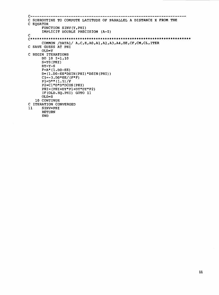
C---------------------------------------------------------------------C SUBROUTINE TO COMPUTE LATITUDE OF PARALLEL A DISTANCE X FROM THE C EQUATOR
FUNCTION SINV(Y,PHI) IMPLICIT DOUBLE PRECISION (A-Z)
c C***********************************************************************
COMMON /DATAl/ A,C,E,AO,Al,A2,A3,A4,EE,CF,CM,CL,ITER C SAVE GUESS AT PHI
OLD=Y C BEGIN ITERATIONS
DO 10 I=l,lO S=YO(PHI) DY=Y-S F=A*(l.DO-EE) D=(l.DO-EE*DSIN(PHI)*DSIN(PHI)) Cl=-3.DO*EE/(F*F) Pl=D**(l.S)/F P2=Cl*D*D*DCOS(PHI) PHI=(PHI+DY*Pl+DY*DY*P2) IF(OLD.EQ.PHI) GOTO 11 OLD=S
10 CONTINUE C ITERATION CONVERGED 11 SINV=PHI
RETURN END
11
12
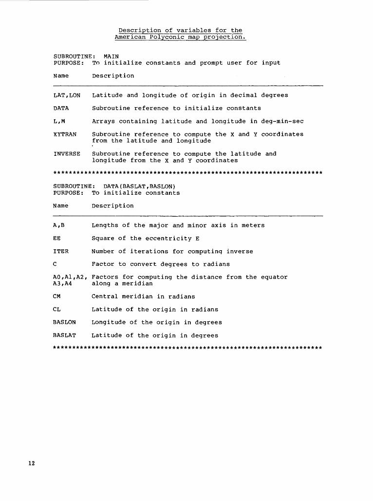
Description of variables for the American Polyconic map projection.
SUBROUTINE: MAIN PURPOSE: To initialize constants and prompt user for input
Name
LAT,LON
DATA
L,M
XYTRAN
INVERSE
Description
Latitude and longitude of origin in decimal degrees
Subroutine reference to initialize constants
Arrays containing latitude and longitude in deg-min-sec
Subroutine reference to compute the X and Y coordinates from the latitude and longitude
Subroutine reference to compute the latitude and longitude from the X and Y coordinates
**********************************************************************
SUBROUTINE: DATA(BASLAT,BASLON) PURPOSE: To initialize constants
Name Description
A,B Lengths of the major and minor axis in meters
EE Square of the eccentricity E
ITER Number of iterations for computinq inverse
c Factor to convert degrees to radians
AO,Al,A2, Factors for computing the distance from the equator A3,A4 along a meridian
CM Central meridian in radians
CL Latitude of the origin in radians
BAS LON Longitude of the origin in degrees
BASLAT Latitude of the origin in degrees
**********************************************************************
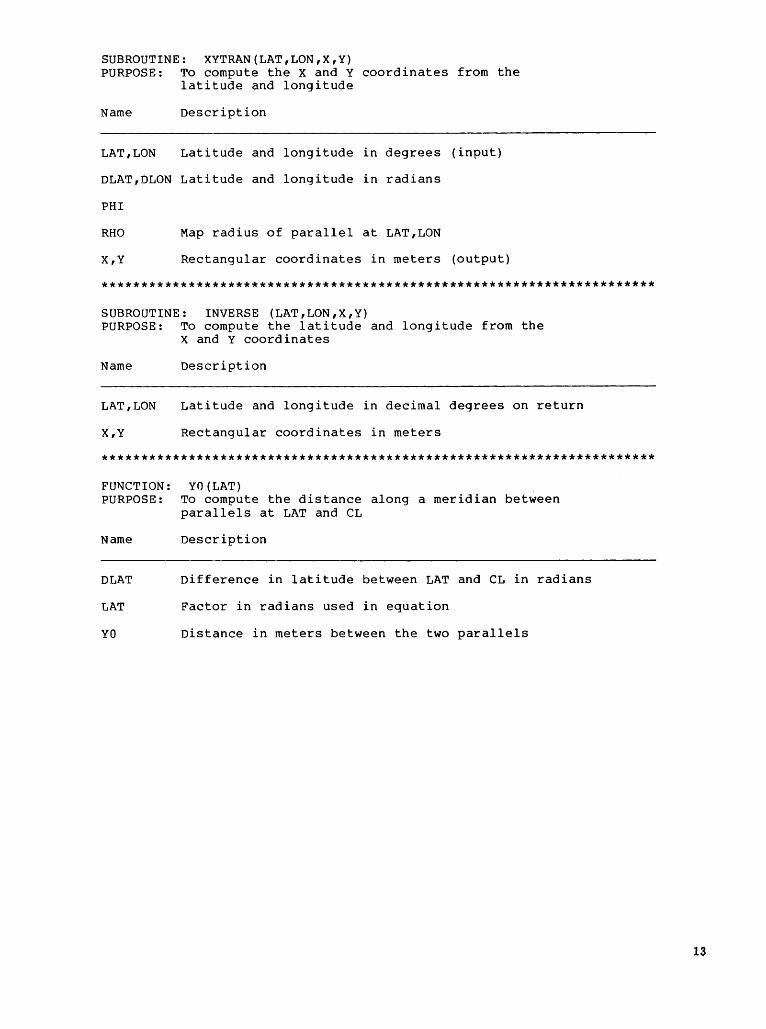
SUBROUTINE: XYTRAN(LAT,LON,X,Y) PURPOSE: To compute the X and Y coordinates from the
latitude and longitude
Name Description
LAT,LON Latitude and longitude in degrees (input)
DLAT,DLON Latitude and longitude in radians
PHI
RHO Map radius of parallel at LAT,LON
X,Y Rectangular coordinates in meters (output)
**********************************************************************
SUBROUTINE: INVERSE (LAT,LON,X,Y) PURPOSE: To compute the latitude and longitude from the
X and Y coordinates
Name Description
LAT,LON Latitude and longitude in decimal degrees on return
X,Y Rectangular coordinates in meters
**********************************************************************
FU~CTION:
PURPOSE:
Name
DLAT
LAT
YO
YO(LAT) To compute the distance along a meridian between parallels at LAT and CL
Description
Difference in latitude between LAT and CL in radians
Factor in radians used in equation
Distance in meters between the two parallels
13
14
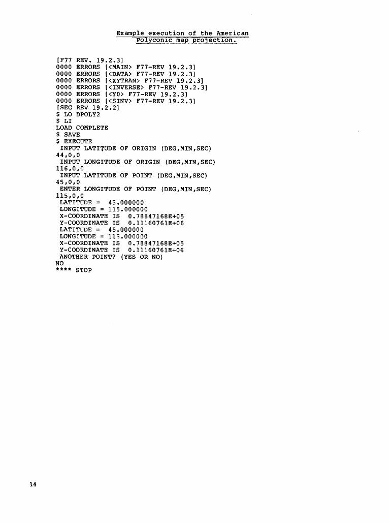
Example execution of the American Polycon1c map pro]ect1on.
[F77 REV. 19.2.3] 0000 ERRORS [<MAIN> F77-REV 19.2.3] 0000 ERRORS [<DATA> F77-REV 19.2.3] 0000 ERRORS [<XYTRAN> F77-REV 19.2.3] 0000 ERRORS [<INVERSE> F77-REV 19.2.3] 0000 ERRORS [<YO> F77-REV 19.2.3] 0000 ERRORS [<SINV> F77-REV 19.2.3] [SEG REV 19.2.2] $ LO DPOLY2 $ LI LOAD COMPLETE $ SAVE $ EXECUTE
INPUT LATITUDE OF ORIGIN (DEG,MIN,SEC) 44,0,0
INPUT LONGITUDE OF ORIGIN (DEG,MIN,SEC) 116,0,0
INPUT LATITUDE OF POINT (DEG,MIN,SEC) 45,0,0
ENTER LONGITUDE OF POINT (DEG,MIN,SEC) 115,0,0
LATITUDE = 45.000000 LONGITUDE = 115.000000 X-COORDINATE IS 0.78847168E+05 Y-COORDINATE IS O.lll60761E+06 LATITUDE = 45.000000 LONGITUDE = 115.000000 X-COORDINATE IS 0.78847168E+05 Y-COORDINATE IS 0.11160761E+06 ANOTHER POINT? (YES OR NO)
NO **** STOP
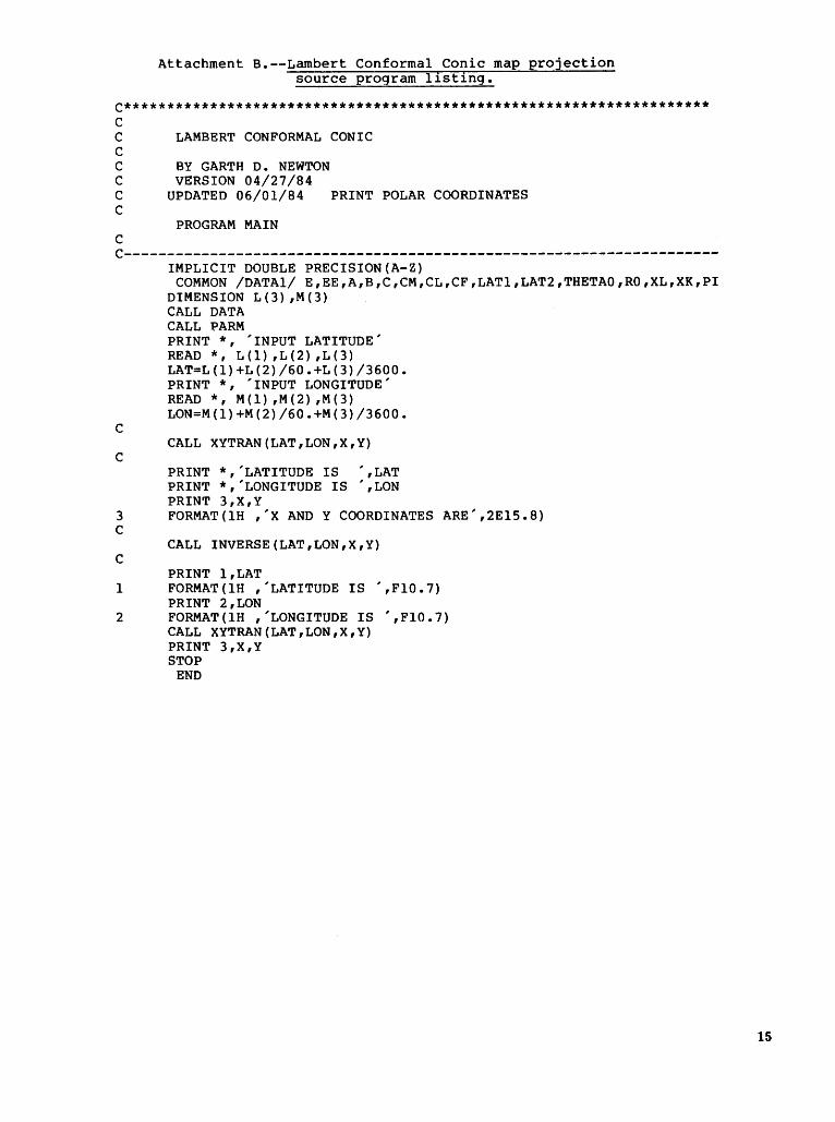
Attachment B.--Lambert Conformal Conic map projection source program l1st1ng.
C******************************************************************** c c c c c c c
c
LAMBERT CONFORMAL CONIC
BY GARTH D. NEWTON VERSION 04/27/84
UPDATED 06/01/84
PROGRAM MAIN
PRINT POLAR COORDINATES
C---------------------------------------------------------------------
c
c
IMPLICIT DOUBLE PRECISION(A-Z) COMMON /DATAl/ E,EE,A,B,C,CM,CL,CF,LATl,LAT2,THETAO,RO,XL,XK,PI
DIMENSION L(3) ,M(3) CALL DATA CALL PARM PRINT*, 'INPUT LATITUDE' READ *, L ( 1) , L ( 2) , L ( 3) LAT=L(l)+L(2)/60.+L(3)/3600. PRINT *, 'INPUT LONGITUDE' READ *, M(l) ,M(2) ,M(3) LON=M(l)+M(2)/60.+M(3)/3600.
CALL XYTRAN(LAT,LON,X,Y)
PRINT *,'LATITUDE IS ',LAT PRINT *,'LONGITUDE IS ',LON PRINT 3,X,Y
3 FORMAT(lH ,'X ANDY COORDINATES ARE',2El5.8) c
CALL INVERSE(LAT,LON,X,Y) c
PRINT l,LAT 1 FORMAT(lH ,'LATITUDE IS ',Fl0.7)
PRINT 2,LON 2 FORMAT(lH ,'LONGITUDE IS ',Fl0.7)
CALL XYTRAN(LAT,LON,X,Y) PRINT 3,X,Y STOP
END
15
16
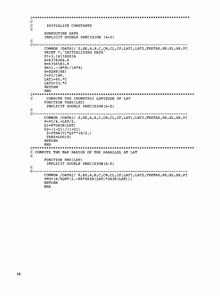
C********************************************************************* c C INITIALIZE CONSTANTS c
SUBROUTINE DATA IMPLICIT DOUBLE PRECISION (A-Z)
c c--------------------------------------------------------------------
coMMON /DATAl/ E,EE,A,B,C,CM,CL,CF,LATl,LAT2,THETAO,RO,XL,XK,PI PRINT *,'INITIALIZING DATA' PI=3.141592654 A=6378206.4 B=6356583.8 EE=l.-(B*B)/(A*A) E=SQRT(EE) C=PI/180. LAT1=45.*C LAT2=33.*C RETURN· END
C*********************************************************************** C COMPUTE THE ISOMETRIC LATITUDE OF LAT
FUNCTION TANZ(LAT) IMPLICIT DOUBLE PRECISION(A-Z)
c c--------------------------------------------------------------------
coMMON /DATAl/ E,EE,A,B,C,CM,CL,CF,LATl,LAT2,THETAO,RO,XL,XK,PI . P=PI/ 4. +LAT/2.
Ql=E*DSIN(LAT) Q2=(1-Ql)/(l+Ql)
Z=DTAN(P)*Q2**(E/2.) TANZ =LOG ( Z)
RETURN END
C*********************************************************************** C COMPUTE THE MAP RADIUS OF THE PARALLEL AT LAT c
FUNCTION RHO(LAT) IMPLICIT DOUBLE PRECISION(A-Z)
c C--------------------------------------------------------------------
COMMON /DATAl/ E,EE,A,B,C,CM,CL,CF,LATl,LAT2,THETAO,RO,XL,XK,PI RHO=(A/SQRT(l.-EE*DSIN(LAT)*DSIN(LAT))) RETURN END
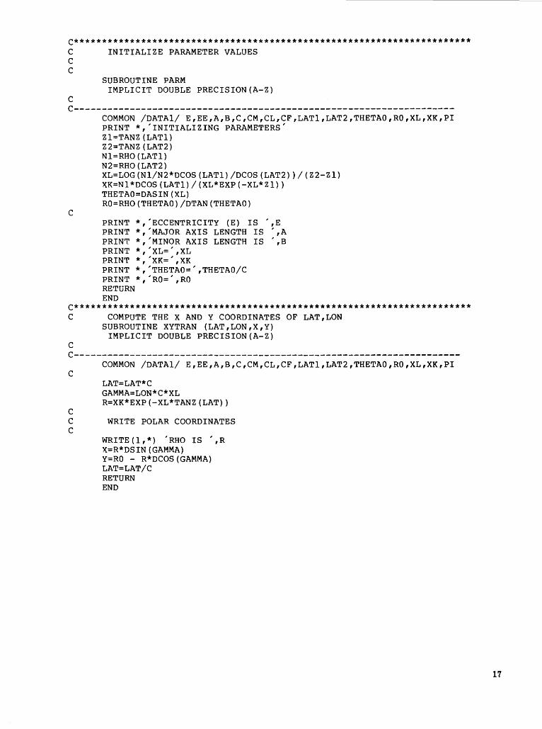
C*********************************************************************** C INITIALIZE PARAMETER VALUES c c
SUBROUTINE PARM IMPLICIT DOUBLE PRECISION(A-Z)
c C--------------------------------------------------------------------
c
COMMON /DATAl/ E,EE,A,B,C,CM,CL,CF,LATl,LAT2,THETAO,RO,XL,XK,PI PRINT *,'INITIALIZING PARAMETERS' Z l=TANZ ( LATl) Z2=TANZ (LAT2) Nl=RHO (LATl) N2=RHO (LAT2) XL=LOG(Nl/N2*DCOS(LAT1)/DCOS(LAT2))/(Z2-Zl) XK=Nl*DCOS(LATl)/(XL*EXP(-XL*Zl)) THETAO=DASIN(XL) RO=RHO(THETAO)/DTAN(THETAO)
PRINT *,'ECCENTRICITY (E) IS ',E PRINT *,'MAJOR AXIS LENGTH IS ',A PRINT *,'MINOR AXIS LENGTH IS ',B PRINT *,'XL=' ,XL PRINT *, 'XK=', XK PRINT *,'THETAO=' ,THETAO/C PRINT *,'RO=' ,RO RETURN END
C*********************************************************************** C COMPUTE THE X AND Y COORDINATES OF LAT,LON
SUBROUTINE XYTRAN (LAT,LON,X,Y) IMPLICIT DOUBLE PRECISION(A-Z)
c c---------------------------------------------------------------------c
c
coMMON /DATAl/ E,EE,A,B,C,CM,CL,CF,LATl,LAT2,THETAO,RO,XL,XK,PI
LAT=LAT*C GAMMA=LON*C*XL R=XK*EXP(-XL*TANZ(LAT))
C WRITE POLAR COORDINATES c
WRITE (1,*) 'RHO IS ',R X=R*DSIN(GAMMA) Y=RO - R*DCOS(GAMMA) LAT=LAT/C RETURN END
17
18
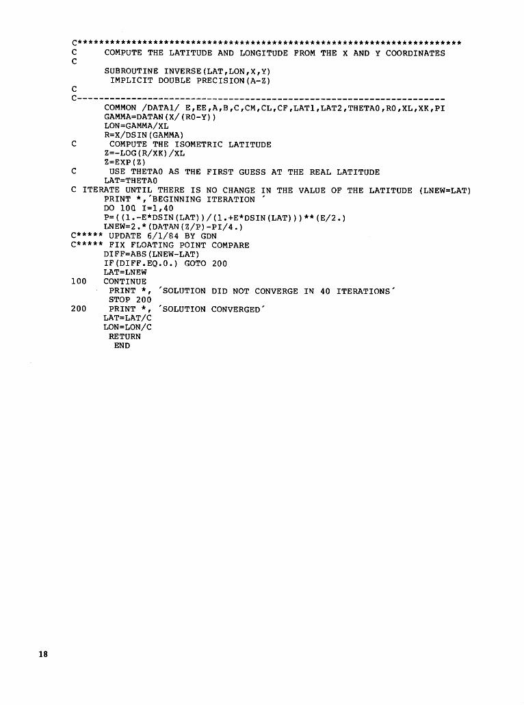
C*********************************************************************** C COMPUTE THE LATITUDE AND LONGITUDE FROM THE X AND Y COORDINATES c
c
SUBROUTINE INVERSE(LAT,LON,X,Y) IMPLICIT DOUBLE PRECISION(A-Z)
c--------------------------------------------------------------------coMMON /DATAl/ E,EE,A,B,C,CM,CL,CF,LATl,LAT2,THETAO,RO,XL,XK,PI GAMMA=DATAN(X/(RO-Y)) LON=GAMMA/XL R=X/DSIN(GAMMA)
C COMPUTE THE ISOMETRIC LATITUDE Z=-LOG(R/XK)/XL Z=EXP(Z)
C USE THETAO AS THE FIRST GUESS AT THE REAL LATITUDE LAT=THETAO
C ITERATE UNTIL THERE IS NO CHANGE IN THE VALUE OF THE LATITUDE (LNEW=LAT) PRINT *,'BEGINNING ITERATION ' DO 100 I=l,40 P=((l.-E*DSIN(LAT))/(l.+E*DSIN(LAT)))**(E/2.) LNEW=2.*(DATAN(Z/P)-PI/4.)
C***** UPDATE 6/1/84 BY GDN C***** FIX FLOATING POINT COMPARE
DIFF=ABS(LNEW-LAT) IF(DIFF.EQ.O.) GOTO 200 LAT=LNEW
100 CONTINUE PRINT*, 'SOLUTION DID NOT CONVERGE IN 40 ITERATIONS' STOP 200
200 PRINT *, 'SOLUTION CONVERGED' LAT=LAT/C LON=LON/C
RETURN END
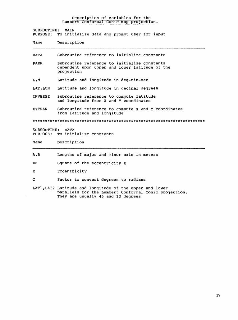
Description of variables for the Lambert Conformal Con1c map proJect1on.
SUBROUTINE: MAIN PURPOSE: To initialize data and prompt user for input
Name
DATA
PARM
L,M
LAT,LON
INVERSE
XYTRAN
Description
Subroutine reference to initialize constants
Subroutine reference to initialize constants dependent upon upper and lower latitude of the projection
Latitude and longitude in deg-min-sec
Latitude and longitude in decimal degrees
Subroutine reference to compute latitude and longitude from X and Y coordinates
SubroutinP reference to compute X and Y coordinates from latitude and lonqitude
**********************************************************************
SUBROUTINE: DATA PURPOSE: To initialize constants
Description
A,B Lengths of major and minor axis in meters
EE Square of the eccentricity E
E Eccentricity
c Factor to convert degrees to radians
LATl,LAT2 Latitude and longitude of the upper and lower parallels for the Lambert Conformal Conic projection. They are usually 45 and 33 degrees
19
20
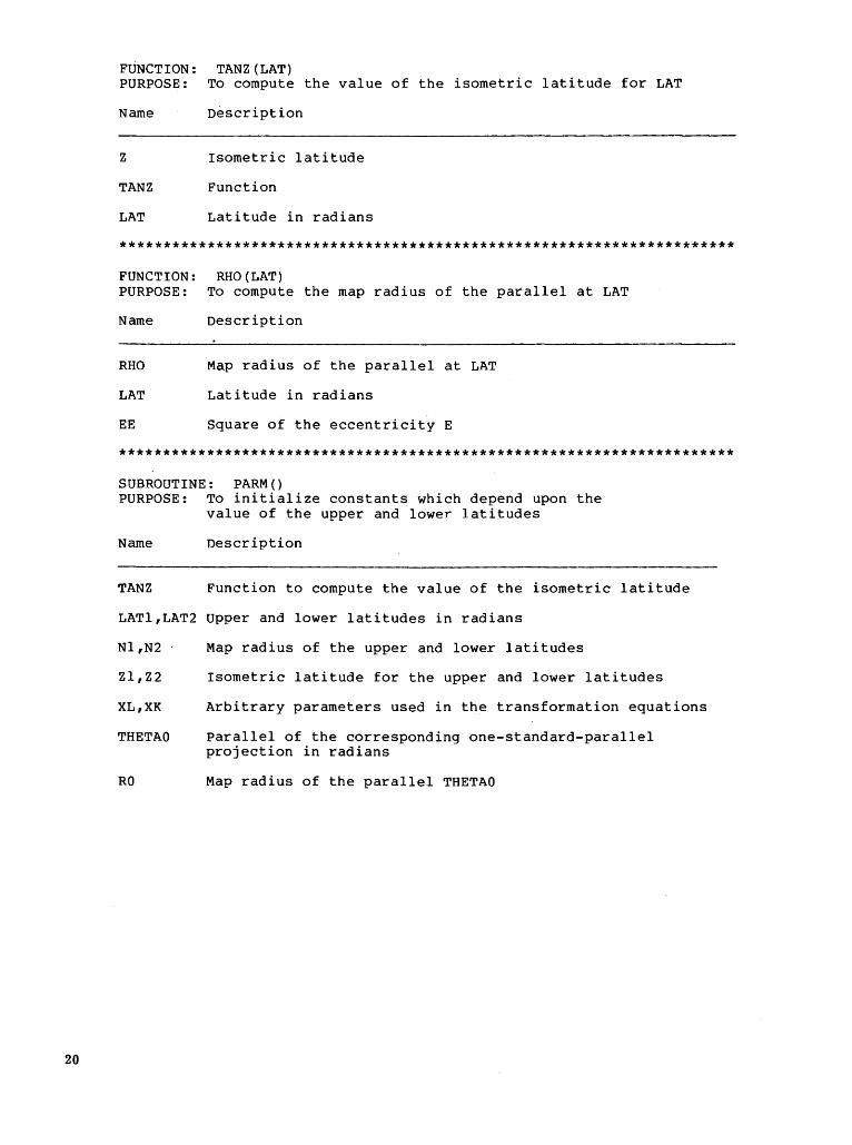
FUNCTION: TANZ(LAT) PURPOSE: To compute the value of the isometric latitude for LAT
Name Description
z Isometric latitude
TANZ Function
LAT Latitude in radians
**********************************************************************
FUNCTION: RHO(LAT) PURPOSE: To compute the map radius of the parallel at LAT
Name Description
RHO Map radius of the parallel at LAT
LAT Latitude in radians
EE Square of the eccentricity E
**********************************************************************
SUBROUTINE: PARM() PURPOSE: To initialize constants which depend upon the
value of the upper and lower latitudes
Name Description
TANZ Function to compute the value of the isometric latitude
LATl,LAT2 Upper and lower latitudes in radians
Nl,N2
Zl,Z2
XL,XK
THETAO
RO
Map radius of the upper and lower latitudes
Isometric latitude for the upper and lower latitudes
Arbitrary parameters used in the transformation equations
Parallel of the corresponding one-standard-parallel projection in radians
Map radius of the parallel THETAO
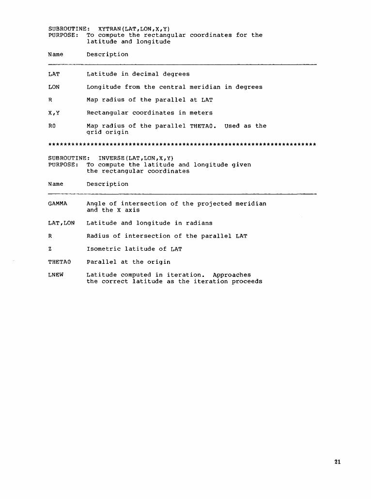
SUBROUTINE: XYTRAN(LAT,LON,X,Y) PURPOSE: To compute the rectangular coordinates for the
latitude and longitude
Name Description
LAT Latitude in decimal degrees
LON Longitude from the central meridian in degrees
R Map radius of the parallel at LAT
X,Y Rectangular coordinates in meters
RO Map radius of the parallel THETAO. used as the qrid origin
**********************************************************************
SUBROUTINE: INVERSE(LAT,LON,X,Y) PURPOSE: To compute the latitude and longitude given
the rectangular coordinates
Name
GAMMA
LAT,LON
R
z
THETAO
LNEW
Description
Angle of intersection of the projected meridian and the X axis
Latitude and longitude in radians
Radius of intersection of the parallel LAT
Isometric latitude of LAT
Parallel at the origin
Latitude computed in iteration. Approaches the correct latitude as the iteration proceeds
21
22
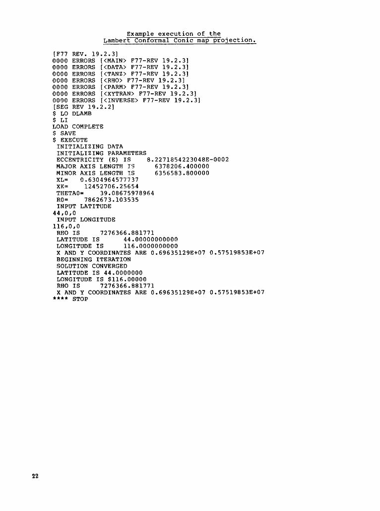
Example execution of the Lambert Conformal Con1c map projection.
[F77 REV. 19.2.3] 0000 ERRORS [<MAIN> F77-REV 19.2.3] 0000 ERRORS [<DATA> F77-REV 19.2.3] 0000 ERRORS [<TANZ> F77-REV 19.2.3] 0000 ERRORS [<RHO> F77-REV 19.2.3] 0000 ERRORS [<PARM> F77-REV 19.2.3] 0000 ERRORS [<XYTRAN> F77-REV 19.2.3] 0000 ERRORS [<INVERSE> F77-REV 19.2.3] [SEG REV 19.2.2] $ LO DLAMB $ LI LOAD COMPLETE $ SAVE $ EXECUTE
INITIALIZING DATA INITIALIZING PARAMETERS ECCENTRICITY (E) IS 8.2271854223048E-0002 MAJOR AXIS LENGTH IS 6378206.400000 MINOR AXIS LENGTH IS 6356583.800000 XL= 0.6304964577737 XK= 12452706.25654 THETAO= 39.08675978964 RO= 7862673.103535 INPUT LATITUDE
44,0;0 INPUT LONGITUDE
116,0,0 RHO IS 7276366.881771 LATITUDE IS 44.00000000000 LONGITUDE IS 116.0000000000 X AND Y COORDINATES ARE 0.69635129E+07 0.57519853E+07 BEGINNING ITERATION SOLUTION CONVERGED LATITUDE IS 44.0000000 LONGITUDE IS $116.00000 RHO IS 7276366.881771 X AND.Y COORDINATES ARE 0.69635129E+07 0.57519853E+07
**** STOP
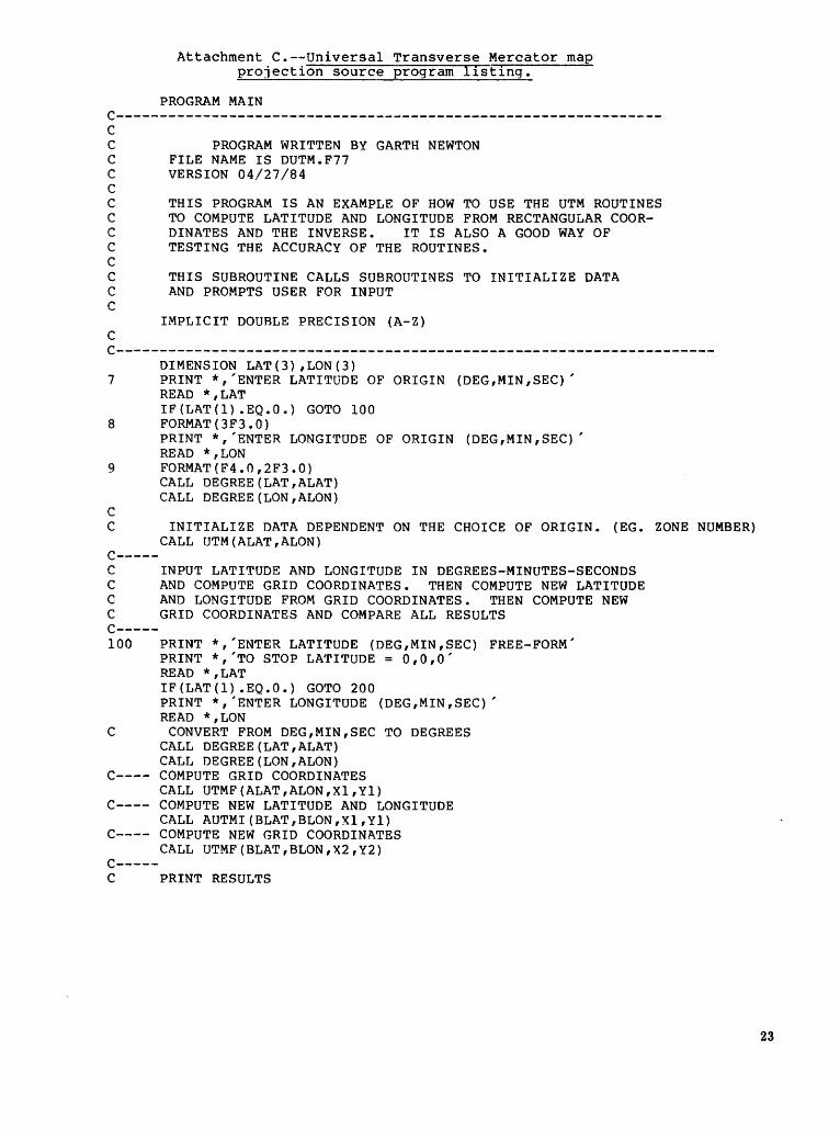
Attachment C.--Universal Transverse Mercator map projection source program l1st1ng.
PROGRAM MAIN C---------------------------------------------------------------C c c c c c c c c c c c c
c
PROGRAM WRITTEN BY GARTH NEWTON FILE NAME IS DUTM.F77 VERSION 04/27/84
THIS PROGRAM IS AN EXAMPLE OF HOW TO USE THE UTM ROUTINES TO COMPUTE LATITUDE AND LONGITUDE FROM RECTANGULAR COORDINATES AND THE INVERSE. IT IS ALSO A GOOD WAY OF TESTING THE ACCURACY OF THE ROUTINES.
THIS SUBROUTINE CALLS SUBROUTINES TO INITIALIZE DATA AND PROMPTS USER FOR INPUT
IMPLICIT DOUBLE PRECISION (A-Z)
C---------------------------------------------------------------------DIMENSION LAT(3) ,LON(3)
7 PRINT *,'ENTER LATITUDE OF ORIGIN (DEG,MIN,SEC)' READ *,LAT IF(LAT(l) .EQ.O.) GOTO 100
8 FORMAT(3F3.0) PRINT *,'ENTER LONGITUDE OF ORIGIN (DEG,MIN,SEC)' READ *,LON
9 FORMAT(F4.0,2F3.0)
c
CALL DEGREE(LAT,ALAT) CALL DEGREE(LON,ALON)
C INITIALIZE DATA DEPENDENT ON THE CHOICE OF ORIGIN. (EG. ZONE NUMBER) CALL UTM(ALAT,ALON)
C-----C INPUT LATITUDE AND LONGITUDE IN DEGREES-MINUTES-SECONDS C AND COMPUTE GRID COORDINATES. THEN COMPUTE NEW LATITUDE C AND LONGITUDE FROM GRID COORDINATES. THEN COMPUTE NEW C GRID COORDINATES AND COMPARE ALL RESULTS C-----100 PRINT *,'ENTER LATITUDE (DEG,MIN,SEC) FREE-FORM'
PRINT *,'TO STOP LATITUDE= 0,0,0' READ *,LAT IF(LAT(l) .EQ.O.) GOTO 200 PRINT *,'ENTER LONGITUDE (DEG,MIN,SEC)' READ *,LON
C CONVERT FROM DEG,MIN,SEC TO DEGREES CALL DEGREE(LAT,ALAT) CALL DEGREE(LON,ALON)
C---- COMPUTE GRID COORDINATES CALL UTMF(ALAT,ALON,Xl,Yl)
C---- COMPUTE NEW LATITUDE AND LONGITUDE CALL AUTMI(BLAT,BLON,Xl,Yl)
C---- COMPUTE NEW GRID COORDINATES CALL UTMF(BLAT,BLON,X2,Y2)
C-----C PRINT RESULTS
23
24
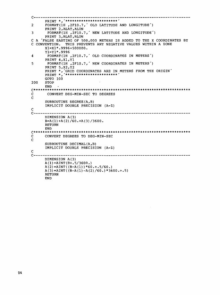
c---------------------------------------------------------------------PRINT *,'***********************'
2 FORMAT(lH ,2Fl0.7,' OLD LATITUDE AND LONGITUDE') PRINT 2,ALAT,ALON
3 FORMAT(lH ,2Fl0.7,' NEW LATITUDE AND LONGITUDE') PRINT 3,BLAT,BLON
C A 'FALSE EASTING OF 500,000 METERS IS ADDED TO THE X COORDINATES BY C CONVENTION. THIS PREVENTS ANY NEGATIVE VALUES WITHIN A ZONE
Xl=Xl*.9996+500000. Yl=Yl*.9996
4 FORMAT(lH ,2Fl0.7,' OLD COORDINATES IN METERS') PRINT 4,Xl,Yl
5 FORMAT(lH ,2Fl0.7,' NEW COORDINATES IN METERS') PRINT 5,X2,Y2 PRINT *,'GRID COORDINATES ARE IN METERS FROM THE ORIGIN' PRINT*,'***********************' GOTO 100
200 STOP END
C********************************************************************* C CONVERT DEG-MIN-SEC TO DEGREES c
SUBROUTINE DEGREE(A,B) IMPLICIT DOUBLE PRECISION (A-Z)
c C---------------------------------------------------------------------
DIMENSION A(3) B=A(l)+A(2)/60.+A(3)/3600. RETURN END
C********************************************************************* C CONVERT DEGREES TO DEG-MIN-SEC c
c
SUBROUTINE DECIMAL(A,B) IMPLICIT DOUBLE PRECISION (A-Z)
c---------------------------------------------------------------------DIMENSION A(3} A(l)=AINT(B+.5/3600.) A"(2)=AINT((B-A(l))*60.+.5/60.) A(3)=AINT((B-A(l)-A(2)/60.)*3600.+.5) RETURN END
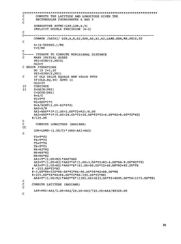
C*********************************************************************** C COMPUTE THE LATITUDE AND LONGITUDE GIVEN THE C RECTANGULAR COORDINATES X AND Y c
c
SUBROUTINE AUTMI(LAT,LON,X,Y) IMPLICIT DOUBLE PRECISION (A-Z)
c---------------------------------------------------------------------c
c
coMMON /DATAl/ D2R,A,B,E2,EPS,AO,Al,A2,LAMO,ERR,MO,PHIO,YO
X=(X-500000.)/MO Y=Y/MO
C----- ITERATE TO COMPUTE MERIDIANAL DISTANCE C MAKE INITIAL GUESS
PHI=SINV(Y,PHIO) OLD=Y
C BEGIN ITERATIONS DO 10 I=l,lO PHI=SINV(Y,PHI)
C IF OLD VALUE EQUALS NEW VALUE STOP IF(OLD.EQ.YO) GOTO 11 OLD= YO
10 CONTINUE 11 S=DSIN(PHI)
c
C=DCOS (PH I) T=S/C T2=T*T N2=EPS*C*C N=A/SQRT(l.DO-E2*S*S) AAO=X/N AAl=AA0**3*(l.D0+2.DO*T2+N2)/6.DO AA2=AA0**5*(5.D0+28.DO*T2+24.DO*T2*T2+6.DO*N2+8.DO*T2*N2) ~/120.DO
C COMPUTE LONGITUDE (RADIANS) cc
c
c
LON=LAMO-(l.DO/C)*(AAO-AAl+AA2)
T3=T*T2 T4=T*T3 T5=T*T4 T6=T*T5 N4=N2*N2 N6=N4*N2 N8=N6*N2 AAl=T*(l.DO+N2)*AAO*AAO . AA2=T*(l.DO+N2)*AA0**4*(5.D0+3.DO*T2+N2-4.DO*N4-9.DO*N2*T2) AA3=T*(l.DO+N2)*AA0**6*(6l.D0+90.DO*T2+46.DO*N2+45.DO*T4
# -252.DO*T2*N2 #-3.DO*N4+100*N6-66*T2*N4-90.DO*T4*N2+88.DO*N8 ~+225.DO*T4*N4+84.DO*T2*N6-192.DO*T2*N8)
AA4=T*(l.DO+N2)*AA0**8*(1385.D0+3633.DO*T2+4095.DO*T4+1575.DO*T6)
C COMPUTE LATITUDE (RADIANS) c
LAT=PHI-AA1/2.DO+AA2/24.DO-AA3/720.DO+AA4/40320.DO c
25
26
c CONVERT TO DEGREES LAT=LAT /D2R LON=LON /D2R
c RETURN END
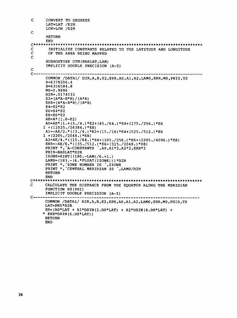
C********************************************************************* C INITIALIZE CONSTANTS RELATED TO THE LATITUDE AND LONGITUDE C OF THE AREA BEING MAPPED c
c
SUBROUTINE UTM(BASLAT,LAM) IMPLICIT DOUBLE PRECISION (A-Z)
c---------------------------------------------------------------------coMMON /DATAl/ D2R,A,B,E2,EPS,AO,Al,A2,LAMO,ERR,MO,PHIO,YO A~6378206.4
B=6356584.8 M0=0.9996 D2R=.Ol74533 E2=(A~A-B*B)/(A*A) EPS=(A*A-B*B)/(B*B) E4=E2*E2 E6=E4*E2 E8=E6*E2 AE=A*(l.O-E2) AO=AE*(l.+(3./4.)*E2+(45./64.)*E4+(175./256.)*E6
1 +(11025./16384.)*E8) Al=-AE/2.*((3./4.}*E2+(15./16)*E4+(525./512.}*E6
i +(2205./2048.}*E8) A2=AE/4.*((15./64.)*E4+(105./256.)*E6+(2205./4096.)*E8) ERR=-AE/6.*((35./512.)*E6+(315./2048.)*E8) PRINT *, 'A-CONS'rANTS ',AO ,Al*2 ,A2*2 ,ERR*2 PHIO=BASLAT*D2R IZONE=AINT((l80.-LAM)/6.+1.) LAMO=(l83.-(6.*FLOAT(IZONE)))*D2R PRINT *,'ZONE NUMBER IS ',!ZONE PRINT *,'CENTRAL MERIDIAN IS ',LAMO/D2R RETURN END
C******~************************************************************** C CALCULATE THE DISTANCE FROM THE EQUATOR ALONG THE MERIDIAN
FUNCTION SS (PHI) IMPLICIT DOUBLE PRECISION (A-Z)
C--------------------------------------------------------------------COMMON /DATAl/ D2R,A,B,E2,EPS,AO,Al,A2,LAMO,ERR,MO,PHIO,YO LAT=PHI*D2R SS=(AO*LAT + Al*DSIN(2.DO*LAT) + A2*DSIN(4.DO*LAT) +
* ERR*DSIN(6.DO*LAT)) RETURN END
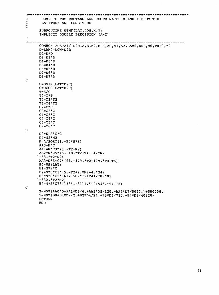
C*********************************************************************** C COMPUTE THE RECTANGULAR COORDINATES X AND Y FROM THE C LATITUDE AND LONGITUDE c
c
SUBROUTINE UTMF(LAT,LON,X,Y) IMPLICIT DOUBLE PRECISION (A-Z)
C---------------------------------------------------------------------
c
c
c
COMMON /DATAl/ D2R,A,B,E2,EPS,AO,Al,A2,LAMO,ERR,MO,PHIO,YO D=LAMO-LON*D2R D2=D*D D3=D2*D D4=D3*D D5=D4*D D6=D5*D D7=D6*D D8=D7*D
S=DSIN(LAT*D2R) C=DCOS(LAT*D2R) T=S/C T2=T*T T4=T2*T2 T6=T4*T2 C2=C*C C3=C2*C C4=C3*C C5=C4*C C6=C5*C C7=C6*C
N2=EPS*C*C N4=N2*N2 N=A/SQRT(l.-E2*S*S) AAO=N*C AAl=N*C3*(1.-T2+N2) AA2=N*C5*(5.-18.*T2+T4+14.*N2
l-58.*T2*N2) AA3=N*S*C7*(61.-479.*T2+179.*T4-T6) BO=SS(LAT) Bl=N*S*C B2=N*S*C3*(5.-T2+9.*N2+4.*N4) B3=N*S*C5*(61.-58.*T2+T4+270.*N2
l-330.*T2*N2) B4=N*S*C7*(1385.-3lll.*T2+543.*T4-T6)
X=MO*(AAO*D+AAl*D3/6.+AA2*D5/120.+AA3*D7/5040.)+500000. Y=MO*(BO+Bl*D2/2.+B2*D4/24.+B3*D6/720.+B4*D8/40320) RETURN END
27
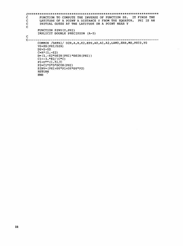
C********************************************************************* C FUNCTION TO COMPUTE THE INVERSE OF FUNCTION SS. IT FINDS THE C LATITUDE OF A POINT A DISTANCE Y FROM THE EQUATOR. PHI IS AN C INITIAL GUESS AT THE LATITUDE OR A POINT NEAR Y c
FUNCTION SINV(Y,PHI) IMPLICIT DOUBLE PRECISION (A-Z)
c C---------------------------------------------------------------------
COMMON /DATAl/ D2R,A,B,E2,EPS,AO,Al,A2,LAMO,ERR,MO,PHIO,YO YO=SS(PHI/D2R) DY=Y-YO C=A*(l.-E2) D=(l.-E2*DSIN(PHI)*DSIN(PHI)) Cl=-3.*E2/(C*C) Pl=D**(l.5)/C P2=Cl*D*D*DCOS(PHI) SINV=(PHI+DY*Pl+DY*DY*P2) RETURN END .
28
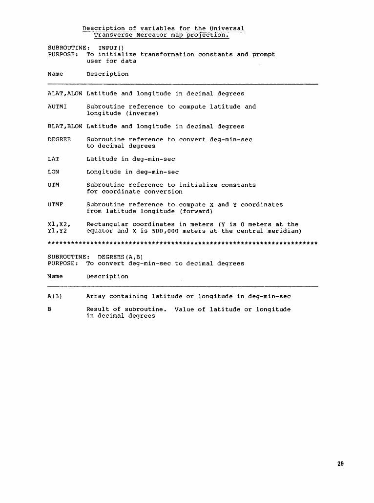
Description of variables for the Universal Transverse Mercator map pro]ect1on.
SUBROUTINE: INPUT() PURPOSE: To initialize transformation constants and prompt
user for data
Name Description
ALAT,ALON Latitude and longitude in decimal degrees
AUTMI Subroutine reference to compute latitude and longitude (inverse)
BLAT,BLON Latitude and longitude in decimal degrees
DEGREE
LAT
LON
UTM
UTMF
Xl,X2, Yl,Y2
Subroutine reference to convert deg-min-sec to decimal degrees
Latitude in deg-min-sec
Longitude in deg-min-sec
Subroutine reference to initialize constants for coordinate conversion
Subroutine reference to compute X and Y coordinates from latitude longitude (forward)
Rectangular coordinates in meters (Y is 0 meters at the equator and X is 500,000 meters at the central meridian)
**********************************************************************
SUBROUTINE: DEGREES(A,B) PURPOSE: To convert deg-min-sec to decimal degrees
Name
A(3)
B
Description
Array containing latitude or longitude in deg-min-sec
Result of subroutine. Value of latitude or longitude in decimal degrees
29

30
SUBROUTINE: DECIMAL(A,B) PURPOSE: To convert decimal degrees to deg-min-sec
Name Description
A ( 3) deg-min-sec
B decimal degrees
*****************************************************************
SUBROUTINE: AUTMI(LAT,LON,X,Y)
PURPOSE: An iterative routine to compute the latitude and longitude of X and Y rectangular coordinates
Name Description
A Length of the major axis in meters
B Length of the minor axis in meters
LAT,LON Latitude and longitude in decimal degrees
X,Y Rectangular coordinates in meters
SINV Function used to compute the latitude of a point a distance Y from the equator along the central meridian
PHI Latitude of a point Y meters from the equator
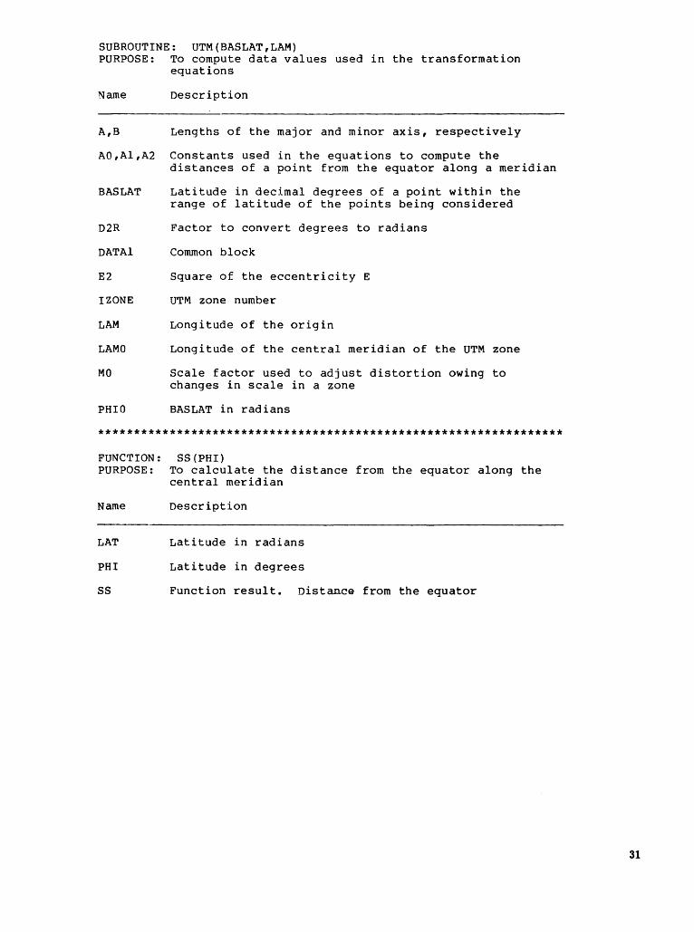
SUBROUTINE: UTM(BASLAT,LAM) PURPOSE: To compute data values used in the transformation
equations
Name Description
A,B Lengths of the major and minor axis, respectively
AO,Al,A2 Constants used in the equations to compute the distances of a point from the equator along a meridian
BASLAT Latitude in decimal degrees of a point within the range of latitude of the points being considered
D2R Factor to convert degrees to radians
DATAl Common block
E2 Square of the eccentricity E
!ZONE UTM zone number
LAM Longitude of the origin
LAMO Longitude of the central meridian of the UTM zone
MO Scale factor used to adjust distortion owing to changes in scale in a zone
PHIO BASLAT in radians
*****************************************************************
FUNCTION: PURPOSE:
Name
LAT
PHI
ss
SS(PHI) To calculate the distance from the equator along the central meridian
Description
Latitude in radians
Latitude in degrees
Function result. Distance from the equator
31
32
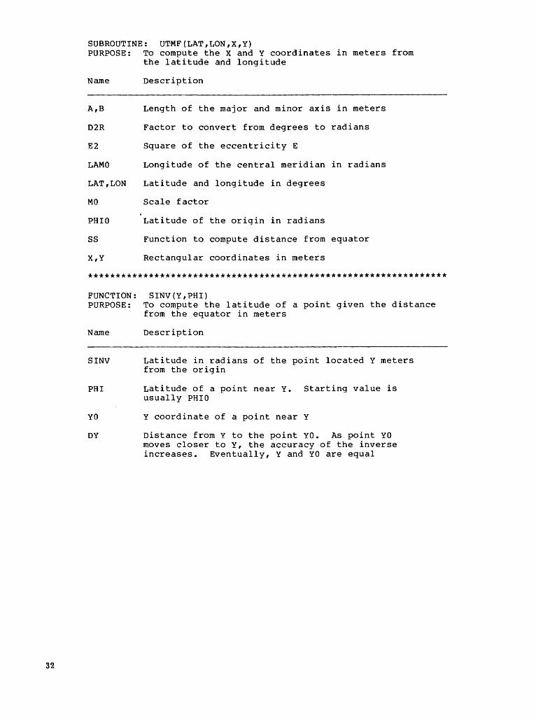
SUBROUTINE: UTMF(LAT,LON,X,Y) PURPOSE: To compute the X and Y coordinates in meters from
the latitude and longitude
Name Description
A,B Length of the major and minor axis in meters
D2R Factor to convert from degrees to radians
E2 Square of the eccentricity E
LAMO Longitude of the central meridian in radians
LAT,LON Latitude and longitude in degrees
MO Scale factor
PHIO Latitude of the origin in radians
ss Function to compute distance from equator
X,Y Rectangular coordinates in meters
*****************************************************************
FUNCTION: PURPOSE:
Name
SINV
PHI
YO
DY
SINV (Y, PHI) To compute the latitude of a point given the distance from the equator in meters
Description
Latitude in radians of the point located Y meters from the origin
Latitude of a point near Y. Starting value is usually PHIO
Y coordinate of a point near Y
Distance from Y to the point YO. As point YO moves closer to Y, the accuracy of the inverse increases. Eventually, Y and YO are equal
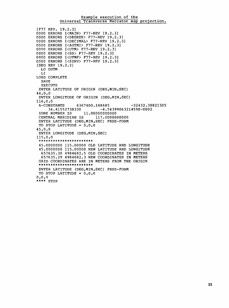
Example execution of the Universal Transverse Mercator map projection.
[F77 REV. 19.2.3] 0000 ERRORS [<MAIN> F77-REV 19.2.3] 0000 ERRORS [<DEGREE> F77-REV 19.2.3] 0000 ERRORS [<DECIMAL> F77-REV 19.2.3] 0000 ERRORS [<AUTMI> F77-REV 19.2.3] 0000 ERRORS [<UTM> F77-REV 19.2.3] 0000 ERRORS [<SS> F77-REV 19.2.3] 0000 ERRORS [<UTMF> F77-REV 19.2.3] 0000 ERRORS [<SINV> F77-REV 19.2.3] [SEG REV 19.2.2]
LO DUTM LI
LOAD COMPLETE SAVE EXECUTE
ENTER LATITUDE OF ORIGIN (DEG,MIN,SEC) 44,0,0
ENTER LONGITUDE OF ORIGIN (DEG,MIN,SEC) 116,0,0
A-CONSTANTS 6367400.188685 -32432.38821305 34.41552738330 -4.5439906321459E-0002
ZONE NUMBER IS 11.00000000000 CENTRAL MERIDIAN IS 117.0000000000 ENTER LATITUDE (DEG,MIN,SEC) FREE-FORM TO STOP LATITUDE = 0,0,0
45,0,0 ENTER LONGITUDE (DEG,MIN,SEC)
115,0,0 *********************** 45.0000000 115.00000 OLD LATITUDE AND LONGITUDE 45.0000000 115.00000 NEW LATITUDE AND LONGITUDE
657635.30 4984682.5 OLD COORDINATES IN METERS 657635.29 4984682.3 NEW COORDINATES IN METERS
GRID COORDINATES ARE IN METERS FROM THE ORIGIN *********************** ENTER LATITUDE (DEG,MIN,SEC) FREE-FORM TO STOP LATITUDE = 0,0,0
o,o,o **** STOP
33


SELECTED SERIES OF U.S. GEOLOGICAL SURVEY PUBLICATIONS
Periodicals
Earthquakes & Volcanoes (issued bimonthly). Preliminary Determination of Epicenters (issued monthly).
Technical Books and Reports
Professional Papers are mainly comprehensive scientific reports of wide and lasting interest and importance to professional scientists and engineers. Included are reports on the results of resource studies and of topographic, hydrologic, and geologic investigations. They also include collections of related papers addressing different aspects of a single scientific topic.
Bulletins contain significant data and interpretations that are of lasting scientific interest but are generally more limited in scope or geographic coverage than Professional Papers. They include the results of resource studies and of geologic and topographic investigations; as well as collections of short papers related to a specific topic.
Water-Supply Papers are comprehensive reports that present significant interpretive results of hydrologic investigations of wide interest to professional geologists, hydrologists, and engineers. The series covers investigations in all phases of hydrology, including hydrogeology, availability of water, quality of water, and use of water.
Circulars present administrative information or important scientific information of wide popular interest in a format designed for distribution at no cost to the public. Information is usually of short-term interest.
Water-Resources Investigations Reports are papers of an interpretive nature made available to the public outside the formal USGS publications series. Copies are reproduced on request unlike formal USGS publications, and they are also avail able for public inspection at depositories indicated in USGS catalogs.
Open-File Reports include unpublished manuscript reports, maps, and other material that are made available for public consultation at depositories. They are a nonpermanent form of publication that may be cited in other publications as sources of information.
Maps
Geologic Quadrangle Maps are multicolor geologic maps on topographic bases in 7 1/2- or 15-minute quadrangle formats (scales mainly 1:24,000 or 1 :62,500) showing bedrock. surficial, or engineering geology. Maps generally include brief texts; some maps include structure and columnar sections only.
Geophysical Investigations Maps are on topographic or planimetric bases at various scales; they show results of surveys using geophysical techniques, such as gravity, magnetic, seismic, or radioactivity, which reflect subsurface structures that are of economic or geologic significance. Many maps include correlations with the geology.
Miscellaneous Investigations Series Maps are on planimetric or topographic bases of regular and irregular areas at various scales; they present a wide variety of format and subject matter. The series also includes 7 1/2-minute quadrangle photo geologic maps on planimetric bases which show geology as interpreted from aerial photographs. Series also includes maps of Mars and the Moon.
Coal Investigations Maps are geologic maps on topographic or planimetric bases at various scales showing bedrock or surficial geology, stratigraphy, and structural relations in certain coal-resource areas.
Oil and Gas Investigations Charts show stratigraphic information for certain oil and gas fields and other areas having petroleum potential.
Miscellaneous Field Studies Maps are multicolor or black-andwhite maps on topographic or planimetric bases on quadrangle or irregular areas at various scales. Pre-1971 maps show bedrock geology in relation to specific mining or mineral-deposit problems; post-1971 maps are primarily black-and-white maps on various subjects such as environmental studies or wilderness mineral investigations.
Hydrologic Investigations Atlases are multicolored or black-andwhite maps on topographic or planimetril- bases presenting a wide range of geohydrologic data of both regular and irregular areas; principal scale is 1:24,000 and regional studies are at 1:250,000 scale or smaller.
Catalogs
Permanent catalogs, as well as some others, giving comprehensive listings of U.S. Geological Survey publications are available under the conditions indicated below from the U.S. Geological Survey, Books and Open-File Reports Section, Federal Center, Box 25425, Denver, CO 80225. (See latest Price and Availability List)
"Publications of the Geological Survey, 1879-1961" may be purchased by mail and over the counter in paperback book form and as a set of microfiche.
"Publications of the Geological Survey, 1962-1970" may be purchased by mail and over the counter in paperback book form and as a set of microfiche.
"Publications ofthe U.S. Geological Survey, 1971-1981" may be purchased by mail and over the counter in paperback book form (two volumes, publications listing and index) and as a set of microfiche.
Supplements for 1982, 1983, 1984, 1985,1986, and for subsequent years since the last permanent catalog may be purchased by mail and over the counter in paperback book form.
State catalogs, "List of U.S. Geological Survey Geologic and Water-Supply Reports and Maps For (State)," may be purchased by mail and over the counter in paperback booklet form only.
"Price and A vailabillty List of U.S. Geological Survey Publications," issued annually, is available free of charge in paperback booklet form only.
Selected copies of a monthly catalog "New Publications of the U.S. Geological Survey" available free of charge by mail or may be obtained over the counter in paperback booklet form only. Those wishing a free subscription to the monthly catalog "New Publications of the U.S. Geological Survey" should write to the U.S. Geological Survey, 582 National Center, Reston, VA 22092.
Note.--Prices of Government publications listed in older catalogs, announcements, and publications may be incorrect. Therefore, the prices charged may differ from the prices in catalogs, announcements, and publications.