Embed Size (px)
Citation preview
JRRDJRRD Volume 49, Number 4, 2012
Pages 567–582
Computer-socket manufacturing error: How much before it is clinically apparent?
Joan E. Sanders, PhD;1–3* Michael R. Severance, MSE;1 Kathryn J. Allyn, CPO1
Departments of 1Bioengineering, 2Rehabilitation Medicine, and 3Mechanical Engineering, University of Washington, Seattle, WA
Abstract—The purpose of this research was to pursue qualitystandards for computer-manufacturing of prosthetic sockets forpeople with transtibial limb loss. Thirty-three duplicates ofstudy participants’ normally used sockets were fabricatedusing central fabrication facilities. Socket-manufacturing errorswere compared with clinical assessments of socket fit. Of the33 sockets tested, 23 were deemed clinically to need modifica-tion. All 13 sockets with mean radial error (MRE) greater than0.25 mm were clinically unacceptable, and 11 of those weredeemed in need of sizing reduction. Of the remaining 20 sockets,5 sockets with interquartile range (IQR) greater than 0.40 mmwere deemed globally or regionally oversized and in need ofmodification. Of the remaining 15 sockets, 5 sockets withclosed contours of elevated surface normal angle error (SNAE)were deemed clinically to need shape modification at thoseclosed contour locations. The remaining 10 sockets weredeemed clinically acceptable and not in need modification.MRE, IQR, and SNAE may serve as effective metrics to charac-terize quality of computer-manufactured prosthetic sockets,helping facilitate the development of quality standards for thesocket manufacturing industry.
Key words: AAOP, alignment, amputee, CAD/CAM, centralfabrication, prosthesis, radial error, socket rectification, socketshape, transtibial.
INTRODUCTION
In recent studies, we found considerable variability inthe quality of prosthetic sockets fabricated by central fabri-cation facilities using computer-socket manufacturing
methods [1–2]. Fabrication errors might not be identifiedby the practitioner until the socket is test-fit to the patientbecause errors are often hard to see by eye. These errorsextend the fitting process because they confound clinicalfitting. The prosthetist must correct errors both from faultymanufacturing and from incorrect socket design, and distin-guishing between the two can be difficult. Further, ifcomputer-socket manufacturing errors are inconsistentfrom one fabrication run to the next and the errors are sub-stantial, a practitioner will have difficulty effectively opti-mizing the socket shape file. This problem might explainwhy there is a wide range in the number of sockets (1 to 5)reported necessary to achieve an acceptable fit in computer-socket design and manufacturing literature [3–6]. Particu-larly for young prosthetists, computer-socket manufac-turing errors can add significant challenge to prostheticdesign.
The purpose of this research was to determine whatmagnitude of socket manufacturing error was clinicallyrelevant and what magnitude was clinically undetectable
Abbreviations: CAD/CAM = computer-aided design/com-puter-aided manufacturing, IQR = interquartile range, MFCL =Medicare Functional Classification Level, MRE = mean radialerror, RVDT = rotational variable differential transformer, SD =standard deviation, SNAE = surface normal angle error.*Address all correspondence to Joan E. Sanders, PhD; Uni-versity of Washington–Bioengineering, 355061 Foege N430J3720 15th Ave NE, Seattle, WA 98195; 206-221-5872; fax:206-685-3300. Email: [email protected]://dx.doi.org/10.1682/JRRD.2011.05.0097
567
568
JRRD, Volume 49, Number 4, 2012
and thus insignificant. This effort will help set manufactur-ing standards in the prosthetics industry. To accomplishthis objective, we compared clinical assessments of socketfit by an experienced practitioner to computer-socket man-ufacturing errors measured with a shape-sensing instru-ment. We developed different computed metrics toidentify different kinds of error (volume, shaping) andthen evaluated how well these computed metrics matchedclinical judgment.
METHODS
SubjectsHuman subject volunteers were included in this
investigation if they had a transtibial amputation at least12 months prior and were a limited community ambulatoror more active (Medicare Functional Classification Level[MFCL] K2). Additionally, subjects needed to regularlyuse an acceptably fitting definitive prosthesis as deemedin clinical examination by the research practitioner. Theprosthetic socket needed to fit properly with less than10-ply sock thickness between the residual limb andsocket. A sock thickness greater than 10 ply was consid-ered indicative of a poorly fitting socket.
Potential subjects were excluded from this investiga-tion if they had skin breakdown or injury on their residuallimb. We also excluded subjects with excessive diurnalresidual-limb volume change, as evidenced by clinicalexam and prosthetic history, because short-term limb vol-ume changes might have confounded the clinical fit eval-uations of interest in this study.
Shape Measurement of Present SocketWe measured the shape of the inside of each subject’s
regular prosthetic socket from the patellar tendon to as fardistally as possible using a custom instrument described indetail elsewhere [1]. The instrument was a very accuratemechanical digitizer that measured the position relativeto a stable base of a low-friction sapphire ball (3.2 mmdiameter) mounted to the tip of a spring-loaded stylus arm.The sapphire ball contacted the inside surface of the socketwhile the socket was rotated about its longitudinal axisusing a stepper motor in the base (SM232AE-NGSN,Compumotor; Rohnert Park, California). After a cross-section was digitized, the stylus arm was moved up using alinear slide rail (ETB32-B08PA99-HRB450L-A, Parker-
Daedal; Columbus, Ohio), and the next cross-section wasdigitized.
The angle of the stylus arm relative to the socket longi-tudinal axis was measured using a rotational variable differ-ential transformer (RVDT) (R30A and ATA 2001,Schaevitz; Hampton, Virginia) mounted to the top of the sty-lus arm, and the stylus arm’s vertical position was measuredusing a linear differential transformer (BTL-5-A/C/E/G1-M457-R-S32, Balluff; Florence, Kentucky) within the linearslide rail. In postprocessing algorithms, we corrected forvertical translation of the stylus tip from rotation of the sty-lus arm about the RVDT axis. The instrument had a radialresolution better than 0.08 mm and measured socket volumedifferences less than 0.1 percent [1–2]. We measured eachsocket from the patellar tendon to the distal end at cross-sections spaced at 0.8 mm. A total of 800 points were mea-sured in each cross-section at angular increments of 0.45°. Ittook approximately 6 h to digitize each socket shape.
We used a different instrument to measure the shape ofthe prosthetic socket above the patellar tendon. After block-ing the proximal anterior and posterior sections with tape,we positioned the socket in a commercial digitizer (d1,Provel; Cle Elum, Washington). The tape ensured that thestylus probe had continuous contact with the surface duringdigitization. Unlike our custom instrument, the Provel digi-tizer was able to digitize the upper socket effectivelybecause the contact probe was large (a 2.0 cm diameterdisk) and did not get stuck in the crevices between thesocket and tape. The digitizer sampled at 120 points perslice at a 5.0 mm slice spacing. After digitizing the entiresocket, we used our custom alignment algorithm, describedhere and in the Appendix (available online only), to alignthe shape measured with our custom instrument with theshape measured with the Provel digitizer. The sectionscommon to both shapes were aligned. We then added theproximal socket section from the Provel digitizer to ourscanner data to make a single electronic shape file for theentire socket. There was error in the proximal section mea-surement because the Provel digitizer, not intended fordetailed investigation of socket shape differences butinstead for capturing residual-limb cast shape as a startingpoint for socket design, was not as accurate as our customshape measurement instrument. The effect of this error onshape analysis results needed to be considered. Using thedata, we created an American Association of Orthotists andProsthetists formatted file at 90 points per slice at a 0.8 mmspacing. The file was used for fabrication of test sockets.
569
SANDERS et al. Clinical effect of socket shape error
Fabrication and Measurement of Test SocketsSix central fabrication facilities were contracted to
make test sockets for the subjects. We selected the facili-ties from those tested in a prior investigation [1]. Twogroups of three facilities each were created. Each groupcontained one facility that previously demonstrated socketshapes well-matched to the electronic shape files and twothat demonstrated moderately to poorly matched shapes.Each subject’s socket shape file was sent to each of thethree facilities within a group, with assignment to thegroup randomly selected. Each facility made a clear checksocket of glycol-modified polyethylene terephthalatematerial and returned it to us untrimmed at the brim. Wemeasured the shape of each fabricated test socket usingour custom instrument. Since the socket was untrimmedwhen we digitized the entire socket with our custominstrument, it was not necessary to use the Provel digitizerto measure the proximal aspect of the socket. After digi-tization, the research practitioner trimmed the socketand filed the brim using standard clinical procedures.After all three test sockets for a subject were prepared, thesubject was scheduled for a test fitting session.
Clinical Evaluation of Test Socket FitUpon arriving at the research laboratory, the subject sat
still for 10 min in a stable chair with the prosthesis on andthe prosthetic foot supported by the floor. This procedurewas performed to achieve a homeostatic condition beforetest fitting. The research practitioner, who had over 8 yearsof clinical experience as a certified prosthetist and over11 years of research experience in prosthetics, queried thesubject about medical and prosthesis history and determinedwhether changes had been made to the prosthesis since thesocket shape was digitized. Any changes were recorded.The subject then removed the prosthesis, and the researchpractitioner inspected the residual limb for signs of break-down or injury. If breakdown or injury was apparent, thenthe subject was released from the study and encouraged tovisit his or her regular prosthetist for socket modification. Ifno breakdown or injury were noted, then the session contin-ued and the subject, wearing the same liner and sock plyused with the regular prosthesis, donned the first test socket.Both the subject and the practitioner were blinded to thefacility that manufactured each test socket, and there wereno distinguishing features that identified any socket’s manu-facturer. In each testing session, we randomized the order inwhich the sockets were tested. Test fitting of each socketproceeded in a manner similar to clinical static fitting [7].
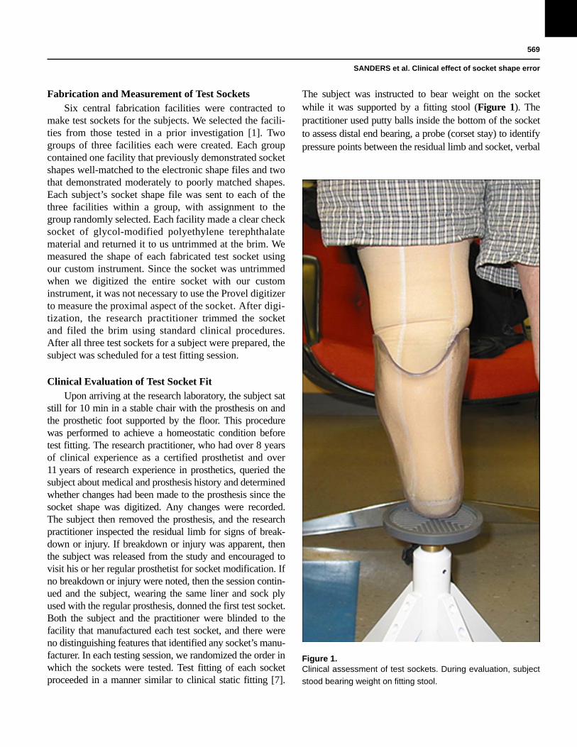
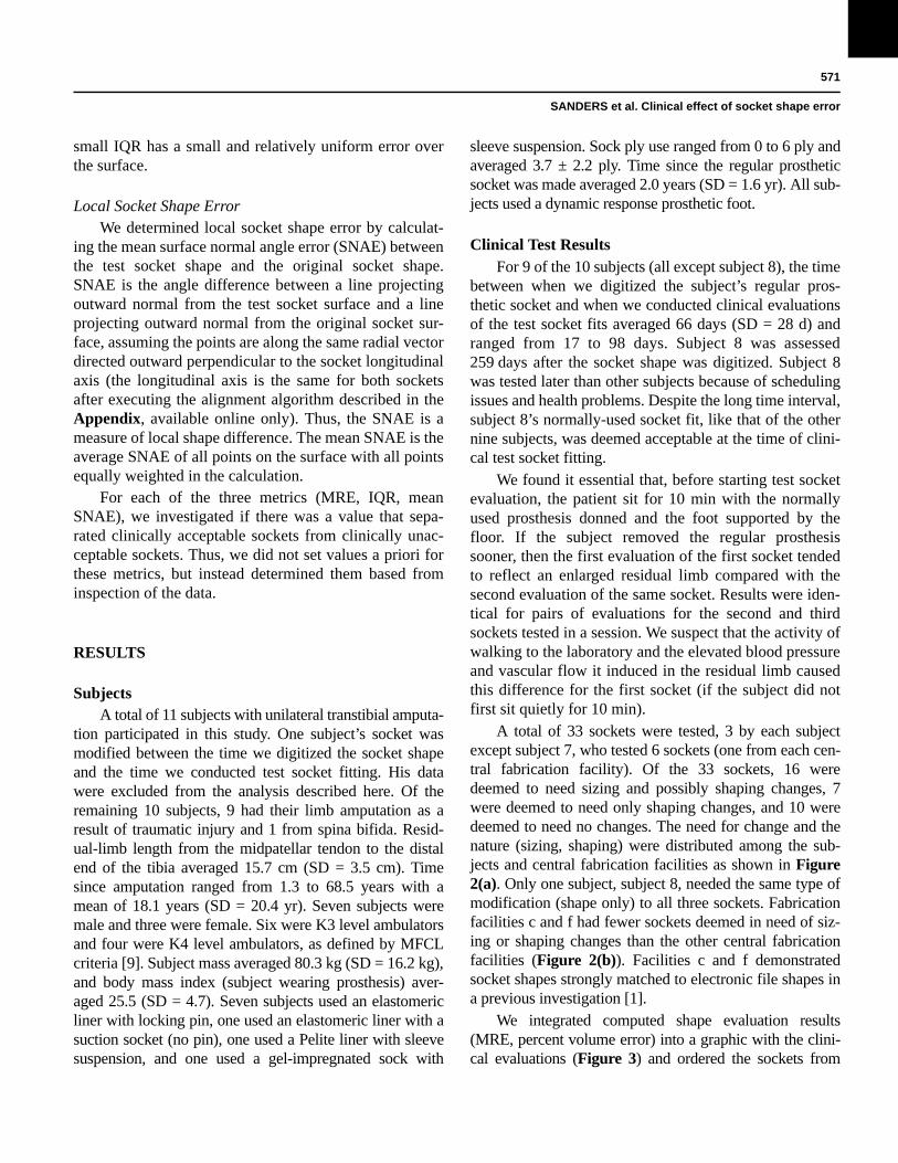
The subject was instructed to bear weight on the socketwhile it was supported by a fitting stool (Figure 1). Thepractitioner used putty balls inside the bottom of the socketto assess distal end bearing, a probe (corset stay) to identifypressure points between the residual limb and socket, verbal
Figure 1.Clinical assessment of test sockets. During evaluation, subject
stood bearing weight on fitting stool.
570
JRRD, Volume 49, Number 4, 2012
feedback from the subject to assess comfort and to identifyproblem areas, and visual inspection of skin color after doff-ing to assess tissue response. The practitioner documentedwhether there was a global sizing problem (i.e., socket toolarge or too small). If sock addition was deemed necessary,then socks were added one at a time (1-ply Soft Sock, Knit-Rite; Kansas City, Kansas). According to manufacturer doc-umentation, the Soft Sock was 90.6 percent polyester, 5percent X-STATIC (Noble Biomaterials Inc; Scranton,Pennsylvania), and 4.4 percent Lycra Spandex (Invista;Wichita, Kansas). X-STATIC is a proprietary silver-basedantimicrobial material. Lycra Spandex is a synthetic fiberwith high elasticity. The socks were new and were not wornat any time other than during the present study. In a separateinvestigation, we determined that this sock model had athickness of 0.45 mm (standard deviation [SD] = 0.03 mm)under loading conditions representative of standing withequal weight-bearing [8]. If two or more 1-ply socks wereadded or if more than two 1-ply sock thickness was deemednecessary for just the proximal region or just the distalregion, in other words if there was a regional socket volumeproblem, then the socket was considered oversized and wasdocumented as having a “sizing and possibly shaping” prob-lem. No further evaluation was conducted on the socket.The basis for this methodology was that in clinical practiceoversizing of a new socket by two 1-ply socks would be, fora patient who does not undergo clinically significant diurnalvolume change, clinically unacceptable and would requiresocket reduction before further test fitting. For sockets with1 ply or no ply added, socket shape was carefully assessed,and the practitioner marked regions deemed too large or toosmall, if they existed, with blue (too large) and red (toosmall) marker on the external socket surface. The socketswere later photographed to document regions in need ofshape modification. It took less than 5 min to assess eachtest socket fit. After evaluation of socket fit was completed,the subject doffed the test socket, donned his or her regularprosthesis, and stood with intermittent weight shifting for2 min. The subject then sat down, doffed the regular pros-thesis, and donned the second test socket. Fit was evaluatedusing the same test procedure. This test was followed by a2 min stand with intermittent weight shifting wearing theregular prosthesis. The third test socket was then evaluatedin a similar manner, followed by a 2 min stand with intermit-tent weight shifting wearing the regular prosthesis. All threesockets were then tested again using the same procedure andin the same order. Careful records were kept of the practitio-ner’s assessment and feedback from the subject.
Alignment of Test Socket Shape with Original Socket Shape
To assess the shape quality of the computer-manufactured sockets, we compared the test socketshapes with the original socket shapes for each subject.Methods for measuring the socket shapes are describedpreviously. To align the shapes, we implemented an opti-mization procedure that involved minimizing the volumedifference and maximizing the shape similarity. A detaileddescription of the alignment algorithm and the mathemati-cal functions used in the optimization are provided in theAppendix (available online only). All socket shapes for asubject were aligned with the same optimization procedureto ensure they were of the same length. To assess sensitiv-ity to weighting of the optimization criteria in the algo-rithm, we compared mean radial error (MRE) results usinga 0.8:0.2 ratio of minimizing volume difference to maxi-mizing shape similarity to results using a 1.0:0.0 ratio.
Computational Evaluation of Test Socket ShapesOnce the test socket shapes were aligned to the origi-
nal socket shapes and the shapes were trimmed at the brim,we carried out three computational analyses. The analysescharacterized the size and shape quality of the test socketscompared with the original sockets. The analysis pro-ceeded in series in a manner similar to the clinical staticfitting procedure described previously, assessing (1) over-all socket volume error, (2) regional socket volume error,and (3) local socket shape error. The metrics we developedfor each are described here.
Overall Socket Volume ErrorWe determined the global volume error for each test
socket by calculating the MRE between the test socketshape and the original socket shape. The MRE is theaverage radial difference between each point on the testsocket compared with its corresponding point (on thesame radial vector) on the original socket.
Regional Socket Volume ErrorWe determined regional volume error by calculating
the interquartile range (IQR) of radial error. IQR is therange of radial error about the MRE between the test socketshape and the original socket shape for the 50 percent ofthe points on the surface that are closest to the MRE.Thus, a test socket with a large IQR has some regions onthe socket that are grossly undersized and other regionsthat are grossly oversized, while a test socket with a
571
SANDERS et al. Clinical effect of socket shape error
small IQR has a small and relatively uniform error overthe surface.
Local Socket Shape ErrorWe determined local socket shape error by calculat-
ing the mean surface normal angle error (SNAE) betweenthe test socket shape and the original socket shape.SNAE is the angle difference between a line projectingoutward normal from the test socket surface and a lineprojecting outward normal from the original socket sur-face, assuming the points are along the same radial vectordirected outward perpendicular to the socket longitudinalaxis (the longitudinal axis is the same for both socketsafter executing the alignment algorithm described in theAppendix, available online only). Thus, the SNAE is ameasure of local shape difference. The mean SNAE is theaverage SNAE of all points on the surface with all pointsequally weighted in the calculation.
For each of the three metrics (MRE, IQR, meanSNAE), we investigated if there was a value that sepa-rated clinically acceptable sockets from clinically unac-ceptable sockets. Thus, we did not set values a priori forthese metrics, but instead determined them based frominspection of the data.
RESULTS
SubjectsA total of 11 subjects with unilateral transtibial amputa-
tion participated in this study. One subject’s socket wasmodified between the time we digitized the socket shapeand the time we conducted test socket fitting. His datawere excluded from the analysis described here. Of theremaining 10 subjects, 9 had their limb amputation as aresult of traumatic injury and 1 from spina bifida. Resid-ual-limb length from the midpatellar tendon to the distalend of the tibia averaged 15.7 cm (SD = 3.5 cm). Timesince amputation ranged from 1.3 to 68.5 years with amean of 18.1 years (SD = 20.4 yr). Seven subjects weremale and three were female. Six were K3 level ambulatorsand four were K4 level ambulators, as defined by MFCLcriteria [9]. Subject mass averaged 80.3 kg (SD = 16.2 kg),and body mass index (subject wearing prosthesis) aver-aged 25.5 (SD = 4.7). Seven subjects used an elastomericliner with locking pin, one used an elastomeric liner with asuction socket (no pin), one used a Pelite liner with sleevesuspension, and one used a gel-impregnated sock with
sleeve suspension. Sock ply use ranged from 0 to 6 ply andaveraged 3.7 ± 2.2 ply. Time since the regular prostheticsocket was made averaged 2.0 years (SD = 1.6 yr). All sub-jects used a dynamic response prosthetic foot.
Clinical Test ResultsFor 9 of the 10 subjects (all except subject 8), the time
between when we digitized the subject’s regular pros-thetic socket and when we conducted clinical evaluationsof the test socket fits averaged 66 days (SD = 28 d) andranged from 17 to 98 days. Subject 8 was assessed259 days after the socket shape was digitized. Subject 8was tested later than other subjects because of schedulingissues and health problems. Despite the long time interval,subject 8’s normally-used socket fit, like that of the othernine subjects, was deemed acceptable at the time of clini-cal test socket fitting.
We found it essential that, before starting test socketevaluation, the patient sit for 10 min with the normallyused prosthesis donned and the foot supported by thefloor. If the subject removed the regular prosthesissooner, then the first evaluation of the first socket tendedto reflect an enlarged residual limb compared with thesecond evaluation of the same socket. Results were iden-tical for pairs of evaluations for the second and thirdsockets tested in a session. We suspect that the activity ofwalking to the laboratory and the elevated blood pressureand vascular flow it induced in the residual limb causedthis difference for the first socket (if the subject did notfirst sit quietly for 10 min).
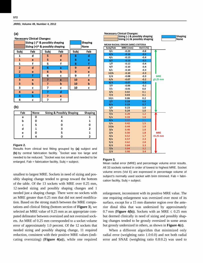
A total of 33 sockets were tested, 3 by each subjectexcept subject 7, who tested 6 sockets (one from each cen-tral fabrication facility). Of the 33 sockets, 16 weredeemed to need sizing and possibly shaping changes, 7were deemed to need only shaping changes, and 10 weredeemed to need no changes. The need for change and thenature (sizing, shaping) were distributed among the sub-jects and central fabrication facilities as shown in Figure2(a). Only one subject, subject 8, needed the same type ofmodification (shape only) to all three sockets. Fabricationfacilities c and f had fewer sockets deemed in need of siz-ing or shaping changes than the other central fabricationfacilities (Figure 2(b)). Facilities c and f demonstratedsocket shapes strongly matched to electronic file shapes ina previous investigation [1].
We integrated computed shape evaluation results(MRE, percent volume error) into a graphic with the clini-cal evaluations (Figure 3) and ordered the sockets from
572
JRRD, Volume 49, Number 4, 2012
smallest to largest MRE. Sockets in need of sizing and pos-sibly shaping change tended to group toward the bottomof the table. Of the 13 sockets with MRE over 0.25 mm,12 needed sizing and possibly shaping changes and 1needed just a shaping change. There were no sockets withan MRE greater than 0.25 mm that did not need modifica-tion. Based on the strong match between the MRE compu-tations and clinical fitting (bottom section of Figure 3), weselected an MRE value of 0.25 mm as an appropriate com-puted delineator between oversized and not oversized sock-ets. An MRE of 0.25 mm corresponded to a socket volumeerror of approximately 1.0 percent. Of the 12 sockets thatneeded sizing and possibly shaping change, 11 requiredreduction, consistent with their positive MRE values (indi-cating oversizing) (Figure 4(a)), while one required
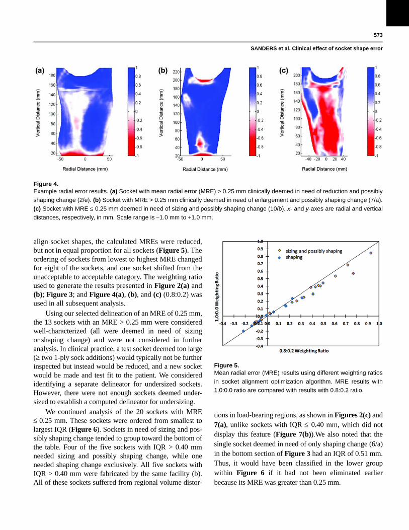
enlargement, inconsistent with its positive MRE value. Theone requiring enlargement was oversized over most of itssurface, except for a 15 mm diameter region over the ante-rior distal tibia that was undersized by approximately0.7 mm (Figure 4(b)). Sockets with an MRE 0.25 mmbut deemed clinically in need of sizing and possibly shap-ing changes tended to be grossly oversized in some areasbut grossly undersized in others, as shown in Figure 4(c).
When a different algorithm that minimized onlyradial error (weighting ratio 1.0:0.0) and not both radialerror and SNAE (weighting ratio 0.8:0.2) was used to
Figure 2.Results from clinical test fitting grouped by (a) subject and
(b) by central fabrication facility. *Socket was too large and
needed to be reduced. ^Socket was too small and needed to be
enlarged. Fab = fabrication facility, Subj = subject.Figure 3.Mean radial error (MRE) and percentage volume error results.
All 33 sockets ranked in order of lowest to highest MRE. Socket
volume errors (Vol E) are expressed in percentage volume of
subject’s normally used socket with brim trimmed. Fab = fabri-
cation facility, Subj = subject.
573
SANDERS et al. Clinical effect of socket shape error
align socket shapes, the calculated MREs were reduced,but not in equal proportion for all sockets (Figure 5). Theordering of sockets from lowest to highest MRE changedfor eight of the sockets, and one socket shifted from theunacceptable to acceptable category. The weighting ratioused to generate the results presented in Figure 2(a) and(b); Figure 3; and Figure 4(a), (b), and (c) (0.8:0.2) wasused in all subsequent analysis.
Using our selected delineation of an MRE of 0.25 mm,the 13 sockets with an MRE > 0.25 mm were consideredwell-characterized (all were deemed in need of sizingor shaping change) and were not considered in furtheranalysis. In clinical practice, a test socket deemed too large(two 1-ply sock additions) would typically not be furtherinspected but instead would be reduced, and a new socketwould be made and test fit to the patient. We consideredidentifying a separate delineator for undersized sockets.However, there were not enough sockets deemed under-sized to establish a computed delineator for undersizing.
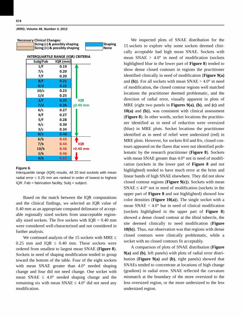
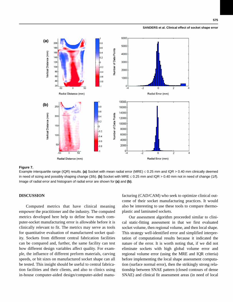
We continued analysis of the 20 sockets with MRE 0.25 mm. These sockets were ordered from smallest tolargest IQR (Figure 6). Sockets in need of sizing and pos-sibly shaping change tended to group toward the bottom ofthe table. Four of the five sockets with IQR > 0.40 mmneeded sizing and possibly shaping change, while oneneeded shaping change exclusively. All five sockets withIQR > 0.40 mm were fabricated by the same facility (b).All of these sockets suffered from regional volume distor-
tions in load-bearing regions, as shown in Figures 2(c) and7(a), unlike sockets with IQR 0.40 mm, which did notdisplay this feature (Figure 7(b)).We also noted that thesingle socket deemed in need of only shaping change (6/a)in the bottom section of Figure 3 had an IQR of 0.51 mm.Thus, it would have been classified in the lower groupwithin Figure 6 if it had not been eliminated earlierbecause its MRE was greater than 0.25 mm.
Figure 4.Example radial error results. (a) Socket with mean radial error (MRE) > 0.25 mm clinically deemed in need of reduction and possibly
shaping change (2/e). (b) Socket with MRE > 0.25 mm clinically deemed in need of enlargement and possibly shaping change (7/a).
(c) Socket with MRE 0.25 mm deemed in need of sizing and possibly shaping change (10/b). x- and y-axes are radial and vertical
distances, respectively, in mm. Scale range is 1.0 mm to +1.0 mm.
Figure 5.Mean radial error (MRE) results using different weighting ratios
in socket alignment optimization algorithm. MRE results with
1.0:0.0 ratio are compared with results with 0.8:0.2 ratio.
574
JRRD, Volume 49, Number 4, 2012
Based on the match between the IQR computationsand the clinical findings, we selected an IQR value of0.40 mm as an appropriate computed delineator of accept-able regionally sized sockets from unacceptable region-ally sized sockets. The five sockets with IQR > 0.40 mmwere considered well-characterized and not considered infurther analysis.
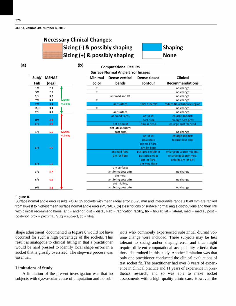
We continued analysis of the 15 sockets with MRE 0.25 mm and IQR 0.40 mm. These sockets wereordered from smallest to largest mean SNAE (Figure 8).Sockets in need of shaping modification tended to grouptoward the bottom of the table. Four of the eight socketswith mean SNAE greater than 4.0° needed shapingchange and four did not need change. One socket withmean SNAE 4.0° needed shaping change and theremaining six with mean SNAE 4.0° did not need anymodification.
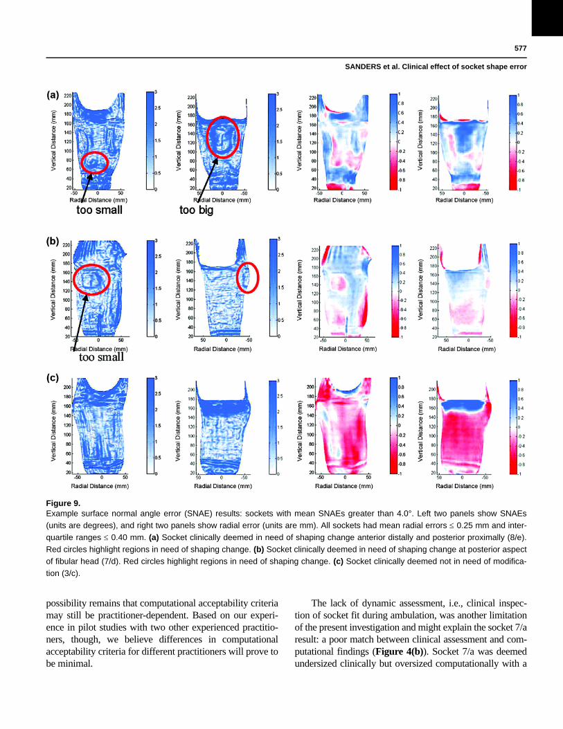
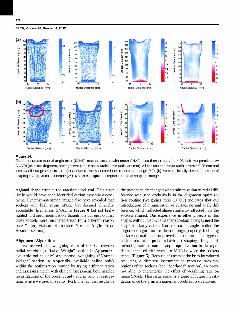
We inspected plots of SNAE distribution for the15 sockets to explore why some sockets deemed clini-cally acceptable had high mean SNAE. Sockets withmean SNAE > 4.0° in need of modification (socketshighlighted blue in the lower part of Figure 8) tended toshow dense closed contours in regions the practitioneridentified clinically in need of modification (Figure 9(a)and (b)). For all sockets with mean SNAE > 4.0° in needof modification, the closed contour regions well matchedlocations the practitioner deemed problematic, and thedirection of radial error, visually apparent in plots ofMRE (right two panels in Figures 9(a), (b), and (c) and10(a) and (b)), was consistent with clinical assessment(Figure 8). In other words, socket locations the practitio-ner identified as in need of reduction were oversized(blue) in MRE plots. Socket locations the practitioneridentified as in need of relief were undersized (red) inMRE plots. However, for sockets 8/d and 8/e, closed con-tours appeared on the flares that were not identified prob-lematic by the research practitioner (Figure 8). Socketswith mean SNAE greater than 4.0° not in need of modifi-cation (sockets in the lower part of Figure 8 and nothighlighted) tended to have much error at the brim andlinear bands of high SNAE elsewhere. They did not showclosed contour regions (Figure 9(c)). Sockets with meanSNAE 4.0° not in need of modification (sockets in theupper part of Figure 8 and not highlighted) showed lowcolor densities (Figure 10(a)). The single socket with amean SNAE < 4.0° but in need of clinical modification(sockets highlighted in the upper part of Figure 8)showed a dense closed contour at the tibial tubercle, thesite deemed clinically to need modification (Figure10(b)). Thus, our observation was that regions with denseclosed contours were clinically problematic, while asocket with no closed contours fit acceptably.
A comparison of plots of SNAE distribution (Figure9(a) and (b), left panels) with plots of radial error distri-bution (Figure 9(a) and (b), right panels) showed thatSNAEs tended to concentrate at locations of high change(gradient) in radial error. SNAE reflected the curvaturemismatch at the boundary of the more oversized to theless oversized region, or the more undersized to the lessundersized region.
Figure 6.Interquartile range (IQR) results. All 20 test sockets with mean
radial error 0.25 mm are ranked in order of lowest to highest
IQR. Fab = fabrication facility, Subj = subject.
575
SANDERS et al. Clinical effect of socket shape error
DISCUSSION
Computed metrics that have clinical meaningempower the practitioner and the industry. The computedmetrics developed here help to define how much com-puter-socket manufacturing error is allowable before it isclinically relevant to fit. The metrics may serve as toolsfor quantitative evaluation of manufactured socket qual-ity. Sockets from different central fabrication facilitiescan be compared and, further, the same facility can testhow different design variables affect quality. For exam-ple, the influence of different preform materials, carvingspeeds, or bit sizes on manufactured socket shape can allbe tested. This insight should be useful to central fabrica-tion facilities and their clients, and also to clinics usingin-house computer-aided design/computer-aided manu-
facturing (CAD/CAM) who seek to optimize clinical out-come of their socket manufacturing practices. It wouldalso be interesting to use these tools to compare thermo-plastic and laminated sockets.
Our assessment algorithm proceeded similar to clini-cal static-fitting assessment in that we first evaluatedsocket volume, then regional volume, and then local shape.This strategy well-identified error and simplified interpre-tation of computational results because it indicated thenature of the error. It is worth noting that, if we did noteliminate sockets with high global volume error andregional volume error (using the MRE and IQR criteria)before implementing the local shape assessment computa-tion (surface normal error), then the strikingly strong rela-tionship between SNAE pattern (closed contours of denseSNAE) and clinical fit assessment areas (in need of local
Figure 7.Example interquartile range (IQR) results. (a) Socket with mean radial error (MRE) 0.25 mm and IQR > 0.40 mm clinically deemed
in need of sizing and possibly shaping change (3/b). (b) Socket with MRE 0.25 mm and IQR > 0.40 mm not in need of change (1/f).
Image of radial error and histogram of radial error are shown for (a) and (b).
576
JRRD, Volume 49, Number 4, 2012
shape adjustment) documented in Figure 8 would not haveoccurred for such a high percentage of the sockets. Thisresult is analogous to clinical fitting in that a practitionerwould be hard pressed to identify local shape errors in asocket that is grossly oversized. The stepwise process wasessential.
Limitations of StudyA limitation of the present investigation was that no
subjects with dysvascular cause of amputation and no sub-
jects who commonly experienced substantial diurnal vol-ume change were included. These subjects may be lesstolerant to sizing and/or shaping error and thus mightrequire different computational acceptability criteria thanthose determined in this study. Another limitation was thatonly one practitioner conducted the clinical evaluations oftest socket fit. The practitioner had over 8 years of experi-ence in clinical practice and 11 years of experience in pros-thetics research, and so was able to make socketassessments with a high quality clinic care. However, the
Figure 8.Surface normal angle error results. (a) All 15 sockets with mean radial error 0.25 mm and interquartile range 0.40 mm are ranked
from lowest to highest mean surface normal angle error (MSNAE). (b) Descriptions of surface normal angle distributions and their link
with clinical recommendations. ant = anterior, dist = distal, Fab = fabrication facility, fib = fibular, lat = lateral, med = medial, post =
posterior, prox = proximal, Subj = subject, tib = tibial.
577
SANDERS et al. Clinical effect of socket shape error
possibility remains that computational acceptability criteriamay still be practitioner-dependent. Based on our experi-ence in pilot studies with two other experienced practitio-ners, though, we believe differences in computationalacceptability criteria for different practitioners will prove tobe minimal.
The lack of dynamic assessment, i.e., clinical inspec-tion of socket fit during ambulation, was another limitationof the present investigation and might explain the socket 7/aresult: a poor match between clinical assessment and com-putational findings (Figure 4(b)). Socket 7/a was deemedundersized clinically but oversized computationally with a
Figure 9.Example surface normal angle error (SNAE) results: sockets with mean SNAEs greater than 4.0°. Left two panels show SNAEs
(units are degrees), and right two panels show radial error (units are mm). All sockets had mean radial errors 0.25 mm and inter-
quartile ranges 0.40 mm. (a) Socket clinically deemed in need of shaping change anterior distally and posterior proximally (8/e).
Red circles highlight regions in need of shaping change. (b) Socket clinically deemed in need of shaping change at posterior aspect
of fibular head (7/d). Red circles highlight regions in need of shaping change. (c) Socket clinically deemed not in need of modifica-
tion (3/c).
578
JRRD, Volume 49, Number 4, 2012
regional shape error at the anterior distal end. This errorlikely would have been identified during dynamic assess-ment. Dynamic assessment might also have revealed thatsockets with high mean SNAE but deemed clinicallyacceptable (high mean SNAE in Figure 8 but not high-lighted) did need modification, though it is our opinion thatthose sockets were mischaracterized for a different reason(see “Interpretation of Surface Normal Angle ErrorResults” section).
Alignment AlgorithmWe arrived at a weighting ratio of 0.8:0.2 between
radial weighting (“Radial Weight” section in Appendix,available online only) and normal weighting (“NormalWeight” section in Appendix, available online only)within the optimization routine by trying different ratiosand assessing match with clinical assessment, both in pilotinvestigations of the present study and in prior investiga-tions where we used this ratio [1–2]. The fact that results in
the present study changed when minimization of radial dif-ference was used exclusively in the alignment optimiza-tion routine (weighting ratio 1.0:0.0) indicates that ourintroduction of minimization of surface normal angle dif-ference, which reflected shape similarity, affected how thesockets aligned. Our experience in other projects is thatshapes without distinct and sharp contour changes need theshape similarity criteria (surface normal angle) within thealignment algorithm for them to align properly. Includingsurface normal angle improved delineation of the type ofsocket fabrication problem (sizing or shaping). In general,including surface normal angle optimization in the algo-rithm increased differences in MRE between the socketstested (Figure 5). Because of errors at the brim introducedby using a different instrument to measure proximalregions of the sockets (see “Methods” section), we werenot able to characterize the effect of weighting ratio onmean SNAE. This issue remains a topic of future investi-gation once the brim measurement problem is overcome.
Figure 10.Example surface normal angle error (SNAE) results: sockets with mean SNAEs less than or equal to 4.0°. Left two panels show
SNAEs (units are degrees), and right two panels show radial error (units are mm). All sockets had mean radial errors 0.25 mm and
interquartile ranges 0.40 mm. (a) Socket clinically deemed not in need of change (5/f). (b) Socket clinically deemed in need of
shaping change at tibial tubercle (2/f). Red circle highlights region in need of shaping change.
579
SANDERS et al. Clinical effect of socket shape error
Global Result ConceptCompanies that demonstrated the greatest percentage
of acceptably fitting sockets also demonstrated socketshapes well-matched to electronic file shapes in our priorinvestigation [1]. Therefore, we conclude that there is noinconsistency in quality in the entire CAD/CAM indus-try. Instead, some facilities consistently practice the art ofsocket fabrication better than others.
Interpretation of Mean Radial Error ResultsThe fact that sockets with large MRE were deemed
clinically too large indicates that MRE was a good quanti-tative measure of volume error, serving well to identifywhat the practitioner detected clinically as an improperlysized socket. For the sockets tested in the present study, anMRE of 0.25 mm reflected approximately a 1.0 percentvolume error. To put this volume in perspective, 0.25 mmis approximately half the thickness of a new 3-ply SoftSock (Knit-Rite) while worn on a residual limb duringwalking [8]. While half of a 3-ply sock may or may notaffect socket comfort, this amount of oversizing at thetime of new socket fitting is problematic. Clinical experi-ence is that oversized sockets induce a greater diurnallimb volume change than properly sized sockets andnecessitate more patient sock changes over the day [10].Thus, manufacturing errors that result in oversizing mayinconvenience the patient. They may also influence socketlongevity. Typically, a patient’s residual limb willdecrease in volume over time, and the patient will addmore socks to compensate. Once sock ply is excessive,more than approximately 10 ply, a new socket needs to bemade. Socket longevity is reduced if the socket is over-sized to begin with. The relationship between degree ofoversizing and degree of reduction in socket longevityremains to be investigated. Understanding this relation-ship may improve cost management in prosthetics.
MRE alone did not identify all sockets with problem-atic fit. Additional computed metrics were needed. Thisresult points to the complexity of prosthetic fitting. Thisresult might be relevant to modeling efforts to predict tis-sue response to changes in socket design [11–16].
Interpretation of Interquartile Range ResultsThe fact that the IQR metric picked up most of the
sockets with sizing error that were not identified by theMRE criterion is consistent with our interpretation thatIQR reflected a combination of sizing and shaping prob-lems, which here we term “regional volume error.” A low
MRE combined with a large IQR meant that, though theoverall volume of the socket was good, the spread inradial error was high. In other words, at least one area ofthe socket was undersized and at least one area was over-sized. The socket shape was distorted. We suspect thatthe practitioner identified these sockets as too bigbecause of the location of the oversizing. All four socketswith MRE 0.25 mm and IQR > 0.40 mm that weredeemed in need or sizing or shaping change were over-sized on the anterior tibial flares and the posterior proxi-mal region. Oversizing at these locations may havecaused the subject’s residual limb to sink deep into thesocket, giving the appearance of socket oversizing duringstatic fit testing.
Sockets from facility b may have consistently shownlow MRE but high IQR (bottom section of Figure 6)because this facility had a consistent manufacturing prob-lem. All of their sockets tended to be too large posteriorproximally and on the anterior tibial flares but too smallanterior distally. Because only six facilities were tested inthis study, we do not know if this problem is unique tothis facility or if a number of central fabrication facilitiesin the industry experience this limitation. However, inour prior investigations more than one facility demon-strated this kind of error [1–2]. Further studies testingmore sockets from other facilities and more subjects willhelp establish if 0.40 mm is an appropriate IQR thresholdfor manufacturing acceptability.
The result that companies may or may not have spe-cific manufacturing problems points to the variability inquality in the central fabrication industry. Not all centralfabrication is performed the same. The industry willimprove as a whole if companies understand their spe-cific manufacturing limitations and address them. Manu-facturers of CAD/CAM equipment can facilitate thisadvance by incorporating tools into their products thatallow customers to conduct evaluations of their socketmanufacturing quality, similar to the assessment devicesdescribed here. Emerging technology, particularly high-quality, small-size imaging systems that allow insidesocket shape to be accurately measured, may facilitatethis advance. To be able to conduct the computationalassessments described here, researchers need an instru-ment that accurately measures socket shape.
Interpretation of Surface Normal Angle Error ResultsThe mean SNAE metric, unlike the MRE and IQR
metrics described previously, mischaracterized some of
580
JRRD, Volume 49, Number 4, 2012
the socket clinical fits (Figure 8). These mischaracteriza-tions may have reflected measurement error in the proxi-mal region of the socket where a different measurementinstrument was used. An additional difficulty was theneed to assemble data from two instruments (Provel digi-tizer; our custom digitizer) within this region. All four ofthe sockets with mean SNAE greater than 4.0° butdeemed clinically acceptable (lower section of Figure 8)had high SNAEs at the brim. It is noteworthy that brimerrors were not sufficient to distort MRE or IQR calcula-tions and interpretations, but they did affect mean SNAE.This happened because surface normal angle was a moresensitive measure to slight mismatches in shape thanwere MRE and IQR. Thus, while SNAE was a very sen-sitive measure and served well to identify local shapeerrors, it was detrimentally affected by digitization errorat the brim.
It is interesting that there are vertical lines within theSNAE plots for most of the sockets (left two panels ofFigure 9(a) to (c) and Figure 10(a) and (b)), but theselines did not match regions identified clinically in error.Instead, closed contours of high SNAE matched regionsidentified clinically as in need of shape modification.Currently, the source of the vertical lines in the SNAEimages is unknown. The lines could reflect our practiceof correcting digitizer contact error in two rather thanthree dimensions [2]. A more accurate representation ofthe surface may be achieved and presence of verticallines in SNAE plots reduced if corrections were made inthree dimensions instead.
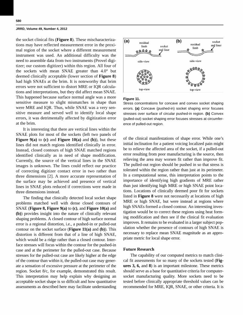
The finding that clinically detected local socket shapeproblems matched well with dense closed contours ofSNAE (Figure 8, Figure 9(a) to (c), and Figure 10(a) and(b)) provides insight into the nature of clinically relevantshaping problems. A closed contour of high surface normalerror is a regional distortion, i.e., a pushed-in or pulled-outcontour on the socket surface (Figure 11(a) and (b)). Thisdistortion is different from that of a line of high SNAE,which would be a ridge rather than a closed contour. Inter-face stresses will focus within the contour for the pushed-incase and at the perimeter for the pulled-out case. Becausestresses for the pulled-out case are likely higher at the edgeof the contour than within it, the pulled-out case may gener-ate a sensation of excessive pressure at the perimeter of theregion. Socket 8/c, for example, demonstrated this result.This interpretation may help explain why designing anacceptable socket shape is so difficult and how quantitativeassessments as described here may facilitate understanding
of the clinical manifestations of shape error. While one’sinitial inclination for a patient voicing localized pain mightbe to relieve the affected area of the socket, if a pulled-outerror resulting from poor manufacturing is the source, thenrelieving the area may worsen fit rather than improve fit.The pulled-out region should be pushed in so that stress istolerated within the region rather than just at its perimeter.In a computational sense, this interpretation points to theimportance of identifying high gradients of MRE ratherthan just identifying high MRE or high SNAE point loca-tions. Locations of clinically deemed poor fit for socketslisted in Figure 8 were not necessarily at locations of highMRE or high SNAE, but were instead at regions wherehigh SNAEs formed a closed contour. An interesting inves-tigation would be to correct these regions using heat form-ing modification and then see if the clinical fit evaluationimproves. It remains to be evaluated in a larger subject pop-ulation whether the presence of contours of high SNAE isnecessary to replace mean SNAE magnitude as an appro-priate metric for local shape error.
Future ResearchThe capability of our computed metrics to match clini-
cal fit assessments for so many of the sockets tested (Fig-ures 3, 6, and 8) is an important milestone. These metricsshould serve as a base for quantitative criteria for computer-socket manufacturing quality. More sockets need to betested before clinically appropriate threshold values can berecommended for MRE, IQR, SNAE, or other criteria. It is
Figure 11.Stress concentrations for concave and convex socket shaping
errors. (a) Concave (pushed-in) socket shaping error focuses
stresses over surface of circular pushed-in region. (b) Convex
(pulled-out) socket shaping error focuses stresses at circumfer-
ence of pulled-out region.
581
SANDERS et al. Clinical effect of socket shape error
also important to consider that some patients may havemore relaxed metric criteria than others (young traumaticinjury patients vs bony elder dysvascular patients, for exam-ple). Further research investigating subject dependence isneeded.
With a base of metrics established, we can pursue anumber of relevant analyses to investigate the effect ofcontrollable manufacturing variables on computer-socketmanufacturing error. For example, how much do differ-ent polymers, e.g., ones that undergo much shrinkageversus those that do not, contribute to sizing error (MRE,IQR) or shaping error (SNAE)? Process variables canalso be evaluated. For example, how sensitive are themetrics for cooling time to transport the socket from theoven to the model and apply vacuum. Do different tech-nicians within a manufacturing facility generate differentMRE, IQR, and SNAE results?
It is our opinion that it is a matter of time before animaging technology is developed to measure the insideshape of a socket with sufficient speed, accuracy, and sensi-tivity to be implemented in computer fabrication equipmentand to be useful to prosthetic socket manufacturing evalua-tion. The prosthetics industry should anticipate this technol-ogy. Incorporating quantitative metrics into computer-socketmanufacturing practice should allow the CAD/CAM indus-try to thrive, in part because using the data to reduce socketfabrication error should make computer-socket fabricationmore cost effective than traditional techniques. Presentingmanufacturing error information to practitioners shouldextend clinical capabilities, enhance judgment, and reducetime to effectively fit prosthetic sockets to patients. Properlyindicating the nature of the error is a significant aspect of thealgorithms developed in the research presented in this arti-cle. This feature should allow the technology to extend thepractitioner’s capabilities in a manner not previous possible.
The insight gained in this research into relationshipsbetween socket shape error and clinical fit might beapplicable to the socket design stage of making a prosthe-sis. An interesting research effort would be to investigaterelationships between socket and residual-limb shape dif-ferences (MRE, IQR, SNAE) and clinical assessment ofsocket fit. This insight may facilitate development ofcomputational tools to extend and enhance practitionerCAD socket design efforts.
An extension of the present study would be to investi-gate variable geometry sockets. Variable geometry socketsare a technology (e.g., Active Contact System, Simbex;Lebanon, New Hampshire) that allows socket shape to be
altered to accommodate diurnal or long-term volumechanges in the residual limb. We expect that variablegeometry sockets will require the practitioner to set adjust-ment of maximum and minimum socket volume so that thesocket is effective and safe for the patient. The alignmentalgorithm and computed metrics described in the presentstudy are potentially useful because they should helpinvestigators to determine if shape adjustments need to bemade in specific regions or whether a global volumeadjustment is acceptable. They should help determine whatrange of socket shapes is appropriate for a patient.
CONCLUSIONS
Computational metrics were developed to character-ize shape quality of computer-manufactured prostheticsockets for people with transtibial limb loss. Comparisonof the metrics with practitioner assessment of socket fitshowed— • An MRE greater than 0.25 mm was associated with
clinical need for socket reduction. • An IQR greater than 0.40 mm was associated with
clinical need for sizing or shape modification. • A closed contour of elevated SNAE was associated
with clinical need for shape modification at the closedcontour.
MRE, IQR, and SNAE may serve as effective metrics tocharacterize the quality of computer-manufactured pros-thetic sockets for people with transtibial limb loss.
ACKNOWLEDGMENTS
Author Contributions:Study concept and design: J. E. Sanders, M. R. Severance, K. J. Allyn.Acquisition of data: M. R. Severance, K. J. Allyn.Analysis and interpretation of data: J. E. Sanders, M. R. Severance, K. J. Allyn.Drafting of manuscript: J. E. Sanders.Critical revision of manuscript for important intellectual content: J. E. Sanders, M. R. Severance, K. J. Allyn.Statistical analysis: M. R. Severance.Obtained funding: J. E. Sanders.Financial Disclosures: The authors have declared that no competing interests exist.Funding/Support: This material was based on work supported by the National Institutes of Health (grant R01HD069387).Institutional Review: We obtained human subjects approval from an internal review board at the University of Washington and obtained informed consent before any study procedures were initiated.
582
JRRD, Volume 49, Number 4, 2012
Participant Follow-Up: The authors do not plan to inform partici-pants of the publication of this study. However, participants have been encouraged to check the study Web site for updated publications.
REFERENCES
1. Sanders JE, Rogers EL, Sorenson EA, Lee GS, AbrahamsonDC. CAD/CAM transtibial prosthetic sockets from centralfabrication facilities: how accurate are they? J Rehabil ResDev. 2007;44(3):395–405. [PMID:18247236]http://dx.doi.org/10.1682/JRRD.2006.06.0069
2. Sanders JE, Severance MR, Myers TR, Ciol MA. Centralfabrication: carved positive assessment. Prosthet OrthotInt. 2011;35(1):81–89. [PMID:21515893]http://dx.doi.org/10.1177/0309364610394476
3. Topper AK, Fernie GR. An evaluation of computer aideddesign of below-knee prosthetic sockets. Prosthet OrthotInt. 1990;14(3):136–42. [PMID:2128892]
4. Ruder GK. CAD CAM trans-tibial temporary prosthesis:analysis and comparison with an established technique.Prosthet Orthot Int. 1992;16(3):189–95. [PMID:1491953]
5. Köhler P, Lindh L, Netz P. Comparison of CAD-CAM andhand made sockets for PTB prostheses. Prosthet Orthot Int.1989;13(1):19–24. [PMID:2717380]
6. Houston VL, Burgess EM, Childress DS, Lehneis HR,Mason CP, Garbarini MA, LaBlanc KP, Boone DA, ChanRB, Harlan JH, Brncick MD. Automated fabrication ofmobility aids (AFMA): below-knee CASD/CAM testingand evaluation program results. J Rehabil Res Dev. 1992;29(4):78–124. [PMID:1432729]http://dx.doi.org/10.1682/JRRD.1992.10.0078
7. Check socket fabrication and fitting. In: New York Univer-sity Post-Graduate Medical School. Lower-limb prosthetics.New York (NY): New York University; 1990. p. 89–91.
8. Sanders JE, Cagle JC, Harrison DS, Karchin A. Amputeesocks: how does sock ply relate to sock thickness? ProsthetOrthot Int. 2012;36(1):77–86. [PMID:22228614]http://dx.doi.org/10.1177/0309364611431290
9. Medicare region C durable medical equipment prostheticsorthotic supplier (DMEPOS) manual. Columbia (SC): Pal-metto GBA; 2005. p. 53.5–53.6.
10. Schnell MD, Bunch WH. Management of pain in theamputee. In: Bowker JH, Michael MW, editors. Atlas oflimb prosthetics: Surgical, prosthetic, and rehabilitation
principles, 2nd ed. St. Louis (MO): Mosby Year Book;1992.
11. Steege JW, Silver-Thorn MB, Childress DS. Design ofprosthetic sockets using finite element analysis. Proceed-ings of the Seventh World Congress of ISPO; 1992 Jun 28–Jul 3; Chicago, Illinois. p. 273.
12. Quesada PM, Skinner HB. Finite element analysis of theeffects of prosthesis model alterations on socket/stumpinterface stresses. Proceedings of the Seventh World Con-gress of ISPO; 1992 Jun 28–Jul 3; Chicago, Illinois. p. 275.
13. Silver-Thorn MB, Childress DS. Sensitivity of below-kneeresidual limb/prosthetic socket interface pressure to variationsin socket design. Proceedings of the Seventh World Congressof ISPO; 1992 Jun 28–Jul 3; Chicago, Illinois. p. 148.
14. Goh JC, Lee PV, Toh SL, Ooi CK. Development of an inte-grated CAD-FEA process for below-knee prosthetic sock-ets. Clin Biomech (Bristol, Avon). 2005;20(6):623–29.[PMID:15927736]http://dx.doi.org/10.1016/j.clinbiomech.2005.02.005
15. Portnoy S, Yarnitzky G, Yizhar Z, Kristal A, Oppenheim U,Siev-Ner I, Gefen A. Real-time patient-specific finite ele-ment analysis of internal stresses in the soft tissues of aresidual limb: a new tool for prosthetic fitting. Ann BiomedEng. 2007;35(1):120–35. [PMID:17120139]http://dx.doi.org/10.1007/s10439-006-9208-3
16. Lee WC, Zhang M. Using computational simulation to aidin the prediction of socket fit: a preliminary study. MedEng Phys. 2007;29(8):923–29. [PMID:17056294]http://dx.doi.org/10.1016/j.medengphy.2006.09.008
Submitted for publication May 31, 2011. Accepted inrevised form October 11, 2011.
This article and any supplementary material should becited as follows:Sanders JE, Severance MR, Allyn KJ. Computer-socketmanufacturing error: How much before it is clinicallyapparent? J Rehabil Res Dev. 2012;49(4):567–82.http://dx.doi.org/10.1682/JRRD.2011.05.0097
ResearcherID: Joan Sanders, PhD: E-8204-2011