Embed Size (px)
Citation preview
Computer Simulation of a Closed Loop Linear Positioning System
Loránd SZABÓ – Ioan-Adrian VIOREL – Zoltán KOVÁCS Technical University of Cluj-Napoca Department of Electrical Engineering
Daicoviciu 15 3400 Cluj-Napoca, Romania
Abstract: The hybrid linear stepper motor is an excellent solution for high speed accurate positioning systems. In order to avoid loss of synchronism a closed-loop control system is necessary. The back EMF generated in the un-energized coil of the motor is monitored in order to determine the commutation moment of the current. The actual velocity of the mover is obtained from an accelerometer. The computer simulation of the linear positioning system, performed by a combined circuit field mathematical model, offers the possibility to calculate the motor parameters, and is an accurate tool for designers. Cite as: Szabó, L. – Viorel, I.A. – Kovács, Z.: Computer Simulation of a Closed Loop Linear Positioning System, Proceedings of the Power Conversion & Intelligent Motion Conference (PCIM '93), Nürnberg (Germany), vol. Intelligent Motion, pp. 142-151.
See attached the scan of the paper
REFERENCES
1. VIOREL, I.A. – KOVACS, Z. – SZABO, L.: Sawyer Type Linear Motor Modelling, Proceedings of the International Conference on Electrical Machines (ICEM '92), Manchester (UK), pp. 697-701, 1992.
2. CHANG L. et al.: Permanent Magnet Synchronous Motor Control: Current Hysteresis Control and Direct Torque Control, Proceedings of the International Conference on Electrical Machines (ICEM '92), Manchester (UK), pp. 918-922.
3. LORENZ, L.: MOS Controlled Power Semiconductor Components for Voltages from 50 V to 2000 V, EPE Journal, vol. 2, no. 2 (June 1992), pp. 77-84.
4. VIOREL, I.A. – SZABO, L. – KOVACS, Quadrature Field Oriented Control of a Linear Stepper Motor, Proceedings of the Power Conversion & Intelligent Motion Conference (PCIM '93), Nürnberg (Germany), vol. Intelligent Motion, pp. 64-73, 1993.
5. ANTOGNINI, L.: Sensorless Driver for PM Brushless and Step Motors, PCIM Europe, vol. 3. (1991), no. 2, pp.64-67.
6. VIOREL, I.A. – KOVACS, Z. – SZABO, L.: Dynamic Modelling of a Closed Loop Drive System of a Sawyer Type Linear Motor, Proceedings of the Power Conversion & Intelligent Motion Conference (PCIM '92), Nürnberg (Germany), vol. Intelligent Motion, pp. 251-257, 1992.

• . �
•• 1:
I', � . a,'
1'8H1113 EUROPE
OFFICIAL PROCEEDINGS
OF THE TWENTYTHIRD INTERNATIONAL
E' ". L7 Lr � G( -" lei .:" " N�;;<: " :) T't ' ,' . .•
. � ::. . � ' " . . " . :," '. . . i' '� , .�
CONFERENCE
JUNE 22 - 24, 1993 NORNBERG, GERMANY
This Book is the Property of
'TIO
INTELLIGENT MOTION· JUNE 1993 PROCEEDINGS I
COMPUTER SIMULATION O F A CLOSED -LOOP LINEAR POSITIONING
SYSTEM
L. SZABO I.A. VIOREL Z. KOVACS
Technical University of Cluj Department of Electrical Engineering
Daicoviciu 15, 3400 Cluj -Napoca, RO}�NIA
ABSTRACT
The hybrid linear stepper motor is an excellent solution for high speed accurate positioning systems. In order to avoid loss of synchronism a closed-loop control system is necessary. The back EM F generated in the un -energized coil of the motor is monitored in order to determine the commutation moment of the current. The actual velocity of the mover is obtained from an accelerometer . The computer simulation of the linear positioning system, performed by a combined circuit-field mathematical model, offers the possibility to calculate the motor parameters, and is an accurate tool for designers.
1. INTHO DUCTION
In recent years requirements for high speed accurate positioning systems used by myriad industries for countless laboratory and production processes have been increasing. The hybrid linear stepper motor is an excellent solution for many of this purposes.
When absolute step integrity or maximum driving force at high load is required a closed -loop control system must be used . This is more expensive then the open -loop control mode because of the need of feedback loops, but enables significant motor efficiency, eliminates mechanical resonances, allows stable operation at high speed. The essential advantage of closed-loop control, as compared to open -loop control, is that step integrity is guaranteed under all load conditions, because the initiation of each step is delayed until the previous step has been satisfactorily completed.
The linear positioning system using hybrid linear stepper motor is a combination of a microprocessor based intelligent
7ontroller and two hysteresis current controlled voltage source �nverters. The controller had been designed for flexible use and
offers a s�lection of control possibilities matched to fulfil several mot�on tasks needed to achieve economic automation of a wi�e varie �y of manUfacturing processes. The primary function of thlS efficlent closed -loop speed control system is to maintain the motor speed at predetermined, load fluctuation independent value.
142 INTELUGENT MOTION· JUNE 1993 PROCEEDINGS
Mas.., 2. £ eca jilt
� -------- - -- -- --- --
aa.
Using a microprocessor based intelligent controller the quadrature field -oriented control of the linear hybrid stepper motor is realized by monitoring the back EM F (electrical mot�ve force) generated in the un-energized coil of the motor. ThlS allows a correct commutation of the command currents of the coils. The measured EM F is totally independent of the phase currents or of any other circuit parameters as resistance and inductance. The actual speed of the motor can be determined by integrating the acceleration signal of the motor obtained from a piezoelectrical accelerometer disposed on the mover. The controller compares the prescribed speed with the actual motor speed. The information thus collected provides guiding the imposed values for the hysteresis current controller. All parameters of the drive system, as step resolution , velocity prof iles, acceleration and deceleration times, current levels during the different move segments, as well as current wave forms can be programmed by the user via software parameters .
The computer simulation of the linear positioning system is performed by using a combined circuit-field mathematical model.
The proposed model is well-suited for the simUlation of both static and dynamic behaviors of the described microprocessor controlled linear positioning system.
2. TH E HYBRID LIN EAR ST EPP ER MOTOR
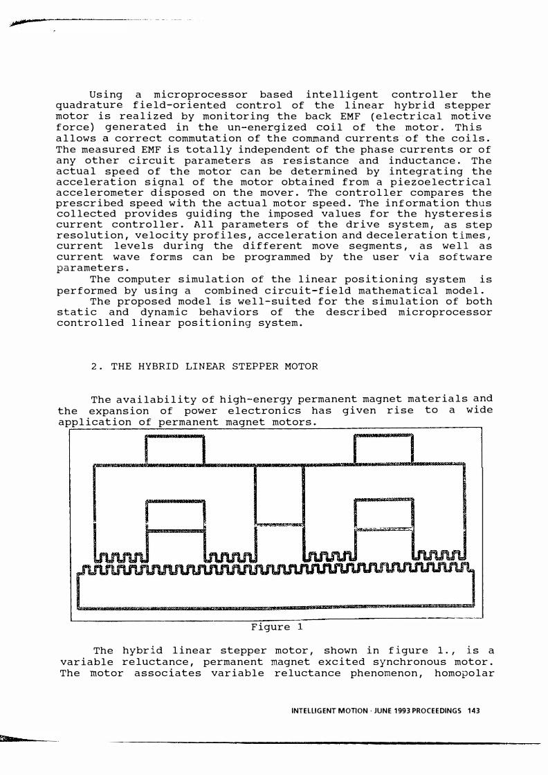
The availability of high-energy permanent magnet materials and the expansion of power electronics has given rise to a wide application of permanent magnet motors.
Figure 1
The hybrid linear stepper motor, shown in figure 1., is a variable reluctance, permanent magnet excited synchronous motor . The motor associates variable reluctance phenomenon, homopolar
INTELLIGENT MOllON . JUNE 1993 PROCEEDINGS 143

permanent magnet bias source and heteropolar coil excitation. The moveable armature (the mover) consists of two electromagnets with coils and a permanent magnet between them, which serves as a bias source. Each electromagnet has two poles, and all poles have the same number of teeth. It is suspended over a fixed stator (the platen), a toothed ferromagnetic structure having the same fine teeth pitch with the moveable armature [1].
The displacement of the motor can be controlled by the sequence of commanding pulses applied to the coils.
3. THE CLOSED-LOOP CONTROL SYSTEM
�--- � � ... ,-" . - - - . . -.'- � _._-- -. _.-
R S T
RECTIFIER
u
I
I i -1 12 INVERiER 1\1101 OR INVERTER
[AJ HYSTEPESIS hYSTEPESIS l
CURRENT CUf�REr"'T
CONTROLLER CONTROLLEP
AND PULSE AI"JD PULSE
GENEPATOP GENERATOP
" " i1 e1 a e2 i2
I i'J T E L L I G E I'--J T CONTROLLER J
Figure 2
I '" I v , ,
For the control of the positioning system using h ybrid linear stepper motor in discussion a direct-time velocity control system (figure 2.) was proposed. The control system is a combination of a
144 INTELUGENT MOTION· JUNE 1993 PROCEEDINGS
�
---
and two hysteresis microprocessor based intelligent controller current controlled voltage source inverters.
The hybrid linear stepper motor is fed by hysteresis controlled voltage source inverters. The currents of the command coils are controlled instantaneously. The control strategy is the following : the actual value of the current is measured, the actual and measured values are compared and an error signal is generated. The hysteresis property of the controller allows the actual value of the current to exceed or to be less than the reference value by a well predetermined value. Small hysteresis bands imply a high switching frequency, which is a practical limitation on the power device switching capability. For a practical compromise between safe operation and low switching frequency a modified hysteresis controller [2] was proposed. This controller detects constantly the current error, but sends new triggering pulses only after a predetermined time interval, selected to be greater than the maximum safe switching period of the semiconductors.
The fire impulses of the two voltage source full-II bridge inverters are def ined taking into account the adopted switch strategy. At low voltages and high switching frequencies power Mosfets are recommended for the inverters [ 3].
The imposed phase currents are prescribed by the controller in such a way as the resulting, load fluctuation independent speed keeps on the imposed velocity profile best suited for the movement of specific load. The commutation of the command current from one to another coil is determined by the peak value of the back EMF detected in the un-energized coil of the motor divided by actual speed [4], [5]. The measured EM F is totally independent of the phase currents or of any other circuit parameters as resistance and inductance.
The velocity feedback loop is closed integrating the movers acceleration obtained by accelerometer disposed on the moveable armature
by sensing and a piezoelectrical [ 6) •
4. THE MATHEMATICA L MODEL O F THE POSITIONING SYSTEM
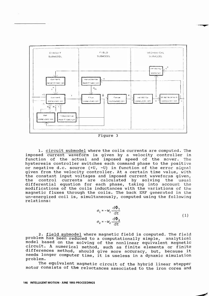
The dynamic behavior of the hybrid linear stepper motor can not be covered accurately by an usual mathematical model because of the compl�x tuothed configuration of armatures, the nonlinearity of the B/H characteristics and magnetic saturation of iron parts and the permanent magnet operating point changes due to air-gap variable reluctance and control amperturns. Therefore a coupled circuit -field model is proposed as being an answer to the problem, which consists of the following three main parts: circuit, field and mechanical submodel (figure 3.).
INTELUGENT MOllON . JUNE 1993 PROCEEDINGS 145
�--- ' --------------------
-----
----------�-----------------I -------------------------------------.-- ------ ------ -- .------- --- -- ----------
CIClCUIT SU8MODEL
1 ,
, 1 /1 "
,
FIELD SU8MOOEL
r"IECH/l,r.J I CAL Sl>81,CDEL
� v
1 , I 1 1 1 ,
,--.-----i , , , , ,
--, : ------
Ii
-------. :' i1 ,
.>( : 1 , 1
�-------------------------------- �-------------------------------------- � ------------------- --- .. ---------- ---- -�
Figure 3
1. circuit submodel where the coils currents are computed. The imposed current waveform is given by a velocity controller in function of the actual and imposed speed of the mover . The hysteresis controller switches each comm and ph ase to the positive or negative d.c. source (+U, -U) in function of the error signal given from the velocity controller. At a certain time value, with the constant input voltages and imposed current waveforms gi ve n, the control currents are c alculated by solving the usual differential equation for e ach phase, t aking into account the modific ations of the coils induct ances with the v ari ations of the magnetic fluxes through the coils. The back EMF generated in the un-energized coil is, simult aneously, computed using the following relations :
d(J)7 e1 = -Wi -crt
dcI>a e2 = -W2"(Jt
(1)
2 . field submodel where magnetic field is computed. The field problem has been reduced to a computationally simple, analytic al model based on the solving of the nonlinear equivalent magnetic circuit. A numerical method, such as finite elements or finite differences method, should give more accuracy, but, because it needs longer computer time, it is useless in a dynamic simulation problem.
The equivalent magnetic circuit of the hybrid linear stepper motor consists of the reluctances associated to the iron cores and
146 INTElUGENT MOTION· JUNE 1993 PROCEEDINGS
- .�
�.
"
.� ..
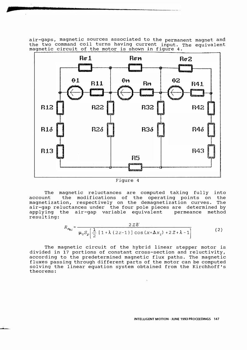
air-gaps, magnetic sources associated to the permanent magnet and the two command coil turns having current input . The equivalent magnetic circuit of the motor is shown in figure 4.
Ru! RUM Ru2
01 OM RM 02
R12 R22 R32
Rlo R26 R3d R46
R13 R5
Figure 4
The magnetic reluctances are computed taking fully into account the modifications of the operating points on the magnetization, respectively on the demagnetization curves . The air-gap reluctances under the four pole pieces are determined by applying the air-gap variable equivalent permeance method resulting:
2 zft R� =
A 1 �OSp[2 [1+1.. (22-1)] COS (x+Axi) +2Z+).-1 ] (2)
The magnetic circuit of the hybrid linear stepper motor is divided in 17 portions of constant cross-section and reluctivity, according to the predetermined magnetic flux paths. The magnetic fluxes passing through different parts of the motor can be computed solving the linear equation system obtained from the Kirchhoff's theorems:
INTELUGENT MOTION· JUNE 1993 PROCEEDINGS 147
•
�l +�2-�S=0
�3 +�3 -�s=O
�l -�7 +�9=0 �4-�8+�11=0
�2 -�6 +�7 -�g +�lO =0 �1 (Rm12 +Rml� +Rm13) -�2 (Rm22 +Rma) +�7Rml1 =81
�2 (Rm22+Rm2�) +�3 (Rm32+Rm311) +cI>sRms+lI>6Rmmp=8mp
-�3 (Rm32+Rm36) +�4 (Rm42+Rm46+Rm43) + <I>8Rm41 =82
�7 {Rmll +/f)gRma1 =81 � 6 Rmmp + <I> loRmamp =8 mp �8Rm41 +�l1Rma2=e2
( 3 )
The platen was considered made by laminated steel, the eddy currents in the platen core were neglected, and so were the amperturns and the forces given by them.
3. mechanical submodel where the position of the moveable armature is computed. The total normal and tangential forces developed by the motor are computed at every time iteration via the air-gap magnetic energy. In addition to the weight of the mover and the friction force they form a simply force structure, resulting the acceleration of the mover. The simultaneous solution of a the mechanical equation defines the speed and the resultant displacement of the motor at each time interval.
The velocity controller compares the imposed speed in accord with the preselected velocity profile and the measured actual speed of the mover. The detected error signal is determined and transferred to the circuit submodel.
The combined field-circuit model is conceived to be solved by means of computer, and the computational process consists of a iterative calculation of the slightly modified parameters of the linear hybrid motor. The computer program based on the proposed model offers the possibility to calculate all the design parameters, and can be an accurate tool for designer.
5. RESULTS AND CONCLUSIONS
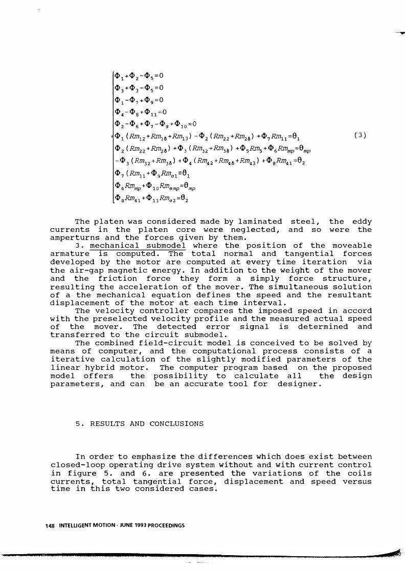
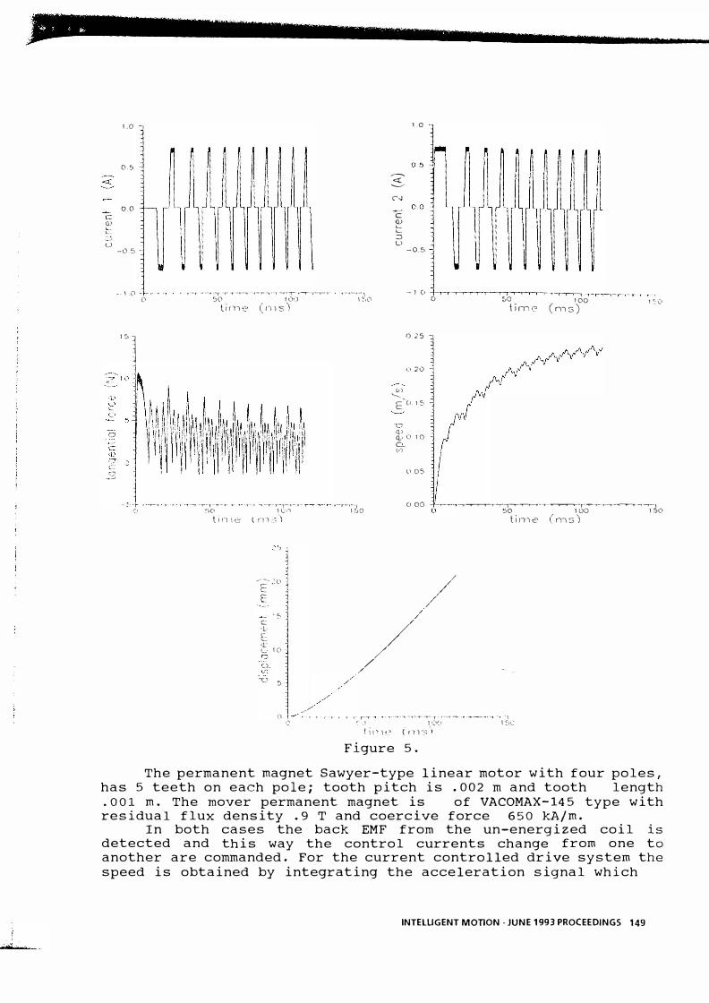
In order to emphasize the differences which does exist between closed-loop operating drive system without and with current control in figure 5. and 6. are presented the variations of the coils currents, total tangential force, displacement and speed versus time in this two considered cases.
148 INTELUGEN T MOTION· JUNE 1993 PROCEEDINGS
• ,. .,
-- ..,...-
"""""'�
....
.:::s
c Q) � � U
-4��
1.0 1.0 L. _ _ .
� ::I U JlJUlJlJUlJ.J J 0.5
0.0 c � � ::l u
-05 -0.5
--, ,0 -t-- '" ' ,--r ---"'--,-"',- -,. '-r-..- '�-""" '-'--'-r'-'-" --'-'- .,.-,---,-, - 1 (I -t-��-.-r-��r--..--�-r�-..._.,.-_r_..,._r_l
15
J
(, 50 IO() \ �,O lin, e ( n , s ')
, • .,.-, , - 'f" -, .. --.- ''--1-'''--'''-' ,- � -,-'f ,'---,.-- T-r---'--'- .--r-'--I
0) .......
0.25
1.).20
E'0.15
'n Q> Q.\ 0 10 0.. t,-)
ll.0S
000
o SO 100 1 �(l time (ms)
--,.--...---.---r-r--r-I��--r--,-�----,-",,--,,--,-.-�-'--r--l C' �'>O 1 (:.� 1.<':'0 a 50 1 00 150
t i " , e (r11 5 ')
"'-;,:-- .�O c E
C 'L-e:: '1.'
.�
f_' 10 Q .-. C�
T� 5-
,// //
.' /' /
///// /
//' ,/
() -l-'-·' .'. , ' , ', • , ,- r-'- ........... -·- ...... ·-,---1· '--'"--' " "1
tin,e (ms ')
'.:' �'.) 1(1(1 1 �Jl.:" I i" , (' (IT) '=;
"
Figure 5.
The permanent magnet Sawyer-type linear motor with four poles, has 5 teeth on each pole; tooth pitch is .002 m and tooth length .001 m. The mover permanent magnet is of VACOMAX-145 type with residual flux density .9 T and coercive force 650 kA/m.
In both cases the back EM F from the un-energized coil is detected and this way the control currents change from one to another are commanded. For the current controlled drive system the speed is obtained by integrating the acceleration signal which
INTELUGENT MonON, JUNE 1993 PROCEEDINGS 149
'.0 1.0
05
3: '--.-/
� � rJ>.r'VVL � 0.0 3�N\JV� -
-YV
VV
-V
L L
:;: o.sll N �
0.0.· l � . --v
J\jV
V-
--
-
JV'
-Jl/\
�1
� , , -0.5
(J + .... �-' ,'-r--r-r- -r--,��_-r--r - , -"-"-',,---�-"""-r- -y- ,-...---..-.,
, 5
() 20 40 60 time (ms)
� u
-0.5 -
- 1.0 --r--r--r-r....--r--T�--,---r--r-'I--,--.,.-l"·-,--r--T-.··'r"·T------.--y--'f-r--r--.. -,-l
0.15
o :::0 40 (,U tinle (ms)
-------z: ----- -------
10 (I) 010 '--... -------�-���-�.-J', Q) 2 E o
-.:::> o Q)
Q) �
c 5 Q)
5}005
CJ1 c .3
��� o I, ' I ---.--,---,---.�� 0.00 r �� o 20 40 60 o 20 time (ms) time
5
----- 4 E E
�3 c OJ E OJ u2 o Cl
.':0 <::>,
// //
o� " " ' 1" , o 20 40 60 time (ms)
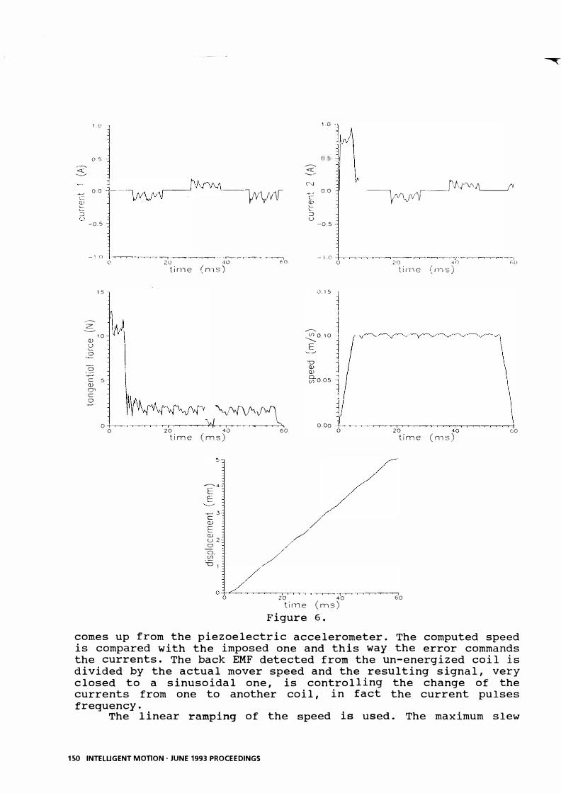
Figure 6.
T 40
(ms) 60
comes up from the piezoelectric accelerometer. The computed speed is compared with the imposed one and this way the error commands the currents. The back EMF detected from the un-energized coil is divided by the actual mover speed and the resulting signal, very closed to a sinusoidal one, is controlling the change of the currents from one to another coil, in fact the current pulses frequency.
The linear ramping of the speed is used. The maximum slew
150 INTELUGENT MonON, JUNE 1993 PROCEEDINGS
�
. ....: ....
j]! r ; PPt' err - • ..
speed (vmax=O,lm/s) is imposed by the needs of the positioning system. The maximum thrust force of the motor Fm x,respectively the motor's and the load mass m defines the maximum gcceleration of the mover:
- Fmax == 1 2 N =20m/s2 (4) amax - m 0 , 6 Kg
The acceleration and deceleration times, taken equals, are:
t == t == Vmax = 0, 1 m/ s = 5 ms (5) a d amax 20 m/ S2
The motor performs a 5 mm long displacement. By evaluating the results obtained on computer model it is
quite clear that the current control loop based on speed detection increases the control accuracy and assures better performances.
6. REFERENCES
1 . VIOREL I.A. - KOVACS Z . - SZABO L. : Sawyer Type Linear Motor Modelling, Proceedings of the International Conference on Electrical Machines 1992, pp. 697-701 .
2. CHANG L. et a 1.: Permanent Magnet Synchronous Motor Control: Current Hysteresis Control and Direct Torque Control, Proceedings of International Conference on Electrical Machines 1992, pp . 918-922.
3 . LORENZ 1.: MOS-Controlled Power Semiconductor Components for Voltages from 50 V to 2000 V, EPE Journ al, vol. 2 ., no . 2 . (june 1992), pp . 77-84 .
4. VIOREL I.A . - SZABO L . - KOVACS Z.: Quadrature Field-Oriented Control of a Linear Stepper Motor, paper to be presented at the PCIM-Intelligent Motion Conference 1993 .
5. ANTOGNINI L .: Sensor less Motors, peIM Europe, vol. 3.
Driver for (1991), no .
PM 2 • ,
Brushless pp .64-67 .
and step
6. VIOREL I .A . - KOVACS Z. - SZABO L .: Dynamic Modelling of a Closed-Loop Drive Sy st em of a Sawyer Type Linear Motor, proceedings of PC IM - I nt e lli gent Motion Conference 1992, pp. 251- 257.
INTELUGENT MonON· JUNE 1993 PROCEEDINGS 151