Embed Size (px)
Citation preview

COMPUTER PERIPHERALSCOMPUTER PERIPHERALSVIDEO CARDVIDEO CARDVOICE CARDVOICE CARD
MODEM AND FAXMODEM AND FAX
PREPARED BY : MOHD FADHIL BIN RAMLE

WHAT IS ADAPTER CARD?WHAT IS ADAPTER CARD?
a circuit board installed in computer to increase the capabilities of that computer.
The card must be match to the bus type of the motherboard (example : install a PCI network card only into a PCI expansion slot).

VIDEO CARDVIDEO CARD
Commonly called video card.To allow the computer to display information on
some kind of monitor or LCD display.Responsible to converting the data sent to it by
the CPU into the pixels, addresses and other items required for display.
Sometimes, video cards can include dedicated chips to perform certain of these functions, thus accelerating the speed of display.
With today’s motherboard, most video cards are AGP and, with increasing popularity, PCIe expansion cards that fit in the associated slot on a motherboard.
VIDEO CARDVIDEO CARD
History of video-display technology:◦ MDA (Monochrome Display Adapter).◦ HGC (Hercules Graphics Card)◦ CGA (Color Graphics Adapter)◦ EGA (Enhanced Graphics Adapter)◦ VGA (Video Graphics Array)◦ SVGA (Super VGA)◦ XGA (Extended Graphics Array)
MDA, HGC, CGA, EGA or MCGA was obsolete.All current display adapter that connect to
the 15-pin VGA analog connector or the DVI analog/digital connector are based on the VGA standard.
VIDEO DISPLAY ADAPTOR

VIDEO CARDVIDEO CARD
Unlike earlier video standards, which are digital, VGA is an analog system.
Most personal computer displays introduced before the PS/2 are digital.
This type of display generates different colors by firing the RGB electron beams in on-or-off mode, which allows for the display of up to eight colors (23). In the IBM displays and adapters, another signal doubles the number of color combinations from 8 to 16 by displaying each color at one of two intensity levels.
VIDEO DISPLAY ADAPTOR
VIDEO CARDVIDEO CARD
Digital display is easy to manufacturer and offers simplicity with consistent color combination from system to system.
The real drawback of the older digital displays such as CGA and EGA is the limited number of possible colors.
In the PS/2 system, IBM went to analog display circuit (April 2, 1987).
Analog displays work like the digital displays but each color in the analog display system can be displayed at varying levels of intensity-64 levels, in the case of VGA.
So, analog system provide 262,144 possible colors (643) of which 256 could be simultaneously displayed.
For realistic computer graphics, color depth is often more important than high resolution because the human eye perceives a picture that has more colors as being more realistic.
VIDEO DISPLAY ADAPTOR
VIDEO CARDVIDEO CARD
Video Graphic ArrayVideo Graphic Arraya purely IBM-defined standardVGA BIOS is the control software residing in the
system ROM for controlling VGA circuits.The VGA can run almost any software that
originally was written for the CGA or EGA.A standard VGA card displays up to 256 colors
onscreen, from a palette of 262,144 (256KB) colors; when used in the 640x400 text mode, 16 colors at a time can be displayed.
Because the VGA outputs an analog signal, you must have a monitor that accepts an analog input.
VIDEO DISPLAY ADAPTOR

VIDEO CARDVIDEO CARD
Also come in monochrome VGA models.64 gray shades are displayed instead of
colors.Uses an algorithm that makes the desired
color and rewrites the formula to involve all three color guns, producing varying intensities of gray.
VIDEO DISPLAY ADAPTOR
VIDEO CARDVIDEO CARD
Super VGASuper VGAwas defined by the Video Electronics
Standards Association (VESA)In that first version, it called for a
resolution of 800 × 600 4-bit pixels (Each pixel could therefore be any of 16 different colours).
extended to 1024 × 768 8-bit pixels, and well beyond that in the following years.
VIDEO DISPLAY ADAPTOR


VIDEO CARDVIDEO CARD
Integrated Video/Motherboard ChipsetsIntegrated Video/Motherboard ChipsetsThe performance and features of built-in
video differed only slightly from add-on cards using the same or similar chipsets.
VIDEO DISPLAY ADAPTOR

Integrated Video Features of Intel 8xx Chipsets

Table 15.9Table 15.9

VIDEO CARDVIDEO CARD
All video adapters contain certain basic components, such as the following:◦ Video BIOS◦ Video processor/video accelerator◦ Video memory◦ Digital-to-analog converter (DAC).◦ Bus connector◦ Video driver
VIDEO DISPLAY ADAPTOR COMPONENTS

VIDEO CARDVIDEO CARDVIDEO DISPLAY ADAPTOR COMPONENTS

VIDEO CARDVIDEO CARD
VIDEO BIOSVIDEO BIOSContaining basic instructions that provide an interface
between the video adapter hardware and the software running on your system.
Enables your system to display information on the monitor during the system POST and boot sequences.
Can be upgraded (use EEPROM).Video BIOS upgrades (sometimes referred as
firmware upgrades) are sometimes necessary in order to use an existing adapter with a new operating system or when manufacturer encounters a significant bug in original programming.
VIDEO DISPLAY ADAPTOR COMPONENTS

VIDEO CARDVIDEO CARD
VIDEO PROCESSORVIDEO PROCESSORThe heart of any video adapter and essentially defines
the card’s functions and performance levels.Two video adapters with the same chipset often have
the same capabilities and deliver comparable performance.
Software drivers that OS and applications use to address the video adapter hardware are written primarily with the chipset.
The video adapter that use the same chipset may differ in the amount and type of memory installed.
VIDEO DISPLAY ADAPTOR COMPONENTS

VIDEO CARDVIDEO CARDVIDEO DISPLAY ADAPTOR COMPONENTS

VIDEO CARDVIDEO CARD
VIDEO AND SYSTEM CHIPSETSVIDEO AND SYSTEM CHIPSETSWhy you should find out which chipset the
video card or video circuit use?:◦ Better comparisons of card or system to others◦ Access to technical specifications◦ Access to reviews and opinions◦ Better buying decisions◦ Choice of card manufacturer or chipset manufacturer support and drivers.
VIDEO DISPLAY ADAPTOR COMPONENTS

VIDEO CARDVIDEO CARD
Video RAMVideo RAMmost video adapters rely on their own onboard
memory to store video images while processing them
Size : 32MB, 64MB or more of onboard memory.Many low-cost system with onboard video use
the universal memory architecture (UMA) feature to share the main system memory.
Memory on the video card or borrowed from the system performs the same tasks.
VIDEO DISPLAY ADAPTOR COMPONENTS

VIDEO CARDVIDEO CARD
Video RAMVideo RAMAmount of memory on the adapter or used by
integrated video determines the maximum screen resolution and color depth the device can support.
Common memory size : 32MB, 64MB and 128MB.
Adding more memory is not guaranteed to speed up your video adapter.
Speed can increase if it enables a wider bus (from 64bits wide to 128bits wide) or provide nondisplay memory as a cache.
VIDEO DISPLAY ADAPTOR COMPONENTS

VIDEO CARDVIDEO CARD
Video RAMVideo RAM
Table 15.11Table 15.11
VIDEO DISPLAY ADAPTOR COMPONENTS

VIDEO CARDVIDEO CARD
Video RAMVideo RAMSGRAM, SDRAM, DDR and DDR-II SDRAM have
replaced VRAM, WRAM and MDRAM as high speed solutions.
VIDEO DISPLAY ADAPTOR COMPONENTS

VIDEO CARDVIDEO CARD
SDRAMSDRAMSynchronous DRAMUsually surface mounted individual chips; on a few
early models, a small module containing SDRAMs might be plugged into proprietary connector.
Designed to work with bus speeds up to 200MHz and provides performance just slightly slower than SGRAM.
Used in current low-end video cards and chipsets such as NVIDIA’s GeForce2 MX and ATI’s RADEON VE.
VIDEO DISPLAY ADAPTOR COMPONENTS

VIDEO CARDVIDEO CARD
SGRAMSGRAMSynchronous Graphics RAM (SGRAM).High-end solution for very fast video adapter
designs.Differs from SDRAM by including circuitry to
perform block writes to increase the speed of graphics fill or 3D Z-buffer operations.
Although SGRAM is faster than SDRAM, most video card makers dropped SGRAM in favor of even faster DDR-SRAM in their newest products.
VIDEO DISPLAY ADAPTOR COMPONENTS

VIDEO CARDVIDEO CARD
DDR SDRAMDDR SDRAMDouble Data Rate SDRAM.Designed to transfer data at speeds twice that of
conventional SDRAM by transferring data on both the rising and falling parts of the processing clock cycle.
Today’s mid-range and low-end video cards based on chipsets such as NVIDIA’s GeForce FX and ATI’s RADEON 9xxx series use DDR SDRAM for video memory.
VIDEO DISPLAY ADAPTOR COMPONENTS

VIDEO CARDVIDEO CARD
DDR-II SDRAMDDR-II SDRAMSecond generation of DDR SDRAM.Fetches 4 bits of data per cycle, instead of 2 as
with DDR SDRAM (double performance at the same clock speed).
First video chipset to support DDR-II was NVIDIA’s GeForce FX.
VIDEO DISPLAY ADAPTOR COMPONENTS

VIDEO CARDVIDEO CARD
GDDR-3 SDRAMGDDR-3 SDRAMBased on DDR-II memory with two major
differences:◦ GDDR-3 separates reads and writes with a single-ended
unidirectional strobe, whereas DDR-II uses differential bidirectional strobes. This method enables much higher data transfer rates.
◦ GDDR-3 uses an interface technique known as pseudo-open drain, which uses voltage instead of current. This method makes GDDR-3 memory compatible with GPUs designed to use DDR or DDR-II memory.
VIDEO DISPLAY ADAPTOR COMPONENTS

VIDEO CARDVIDEO CARD
VIDEO RAM SPEEDVIDEO RAM SPEEDVideo cards with same type 3D graphics
processor chip (GPU) onboard might use different speeds of memory.
Example:◦ Two cards use the NVIDIA GeForce FX 5200-the Prolink
PixelView (4ns memory) and the Chaintech A-FX20 (5ns memory)-use different memory speeds.
◦ Sometimes, video makers also match different memory speeds with different versions of the same basic GPU, as with ATI’s Radeon 9800 XT and 9800 Pro: 9800XT has a core clock speed of 412MHz versus the 9800 Pro’s 380MHz clock speed.
VIDEO DISPLAY ADAPTOR

VIDEO CARDVIDEO CARD
RAM CALCULATIONSRAM CALCULATIONSTo find amount of memory a video adapter needs to
display a particular resolution and color depth.Resolution determines the number of total pixels. For
example, a screen resolution of 1024x768 requires a total 786,432 pixels.
If you were to display that resolution with only two colors, you would need only 1 bit of memory space to represent each pixel.(0=dot is black, 1=dot is white)
If you use 24 bits of memory space to control each pixel, you can display more than 16.7 million colors (224 )
VIDEO DISPLAY ADAPTOR

VIDEO CARDVIDEO CARD
Amount of memory that adapter needs to display that resolution.
1024x768 = 786432 pixels x 24 bits per pixels = 18,874,368 bits = 2,359,296 bytes = 2.25 MB
Because most adapters support memory amounts of only 256KB, 512KB, 1MB, 2MB or 4MB. You would need to use video adapter with at least 4MB of RAM onboard to run your system using that resolution and color depth.
VIDEO DISPLAY ADAPTOR

VIDEO CARDVIDEO CARDVIDEO DISPLAY ADAPTOR

VIDEO CARDVIDEO CARD
DIGITAL-TO-ANALOG CONVERTERDIGITAL-TO-ANALOG CONVERTERCommonly called a RAMDACConvert the digital images your computer generates
into analog signals the monitor can display.Measured in MHz, the higher vertical refresh rates,
allow higher resolutions with flicker-free refresh rates (72Hz-85Hz or above)
Typically, cards with RAMDAC speeds of 300MHz or above display flicker-free at resolutions up to 1920x1200.
Of course, you must ensure that any resolution you want to use is supported by both your monitor and video card.
VIDEO DISPLAY ADAPTOR

VIDEO CARDVIDEO CARD
THE BUSTHE BUSIBM
MCAISAEISAVL-BusPCIAGPPCI-eXPRESS
VIDEO DISPLAY ADAPTOR
OBSOLETE

VIDEO CARDVIDEO CARD
THE BUSTHE BUSAGPDeliver maximum bandwidth up to 16times
larger PCIEnhancement to PCI bus.Use with only video adapterProvides high-speed access to the main system
memory array.Four speed of AGP
VIDEO DISPLAY ADAPTOR

VIDEO CARDVIDEO CARDVIDEO DISPLAY ADAPTOR

VIDEO CARDVIDEO CARD
THE BUSTHE BUSPCI EXPRESS Succeed both AGP and PCI Use high speed bidirectional serial data transfer method. PCI Express channels (also known as lanes) can be
combine to create wider and faster expansion slots (each lanes provides 250MBps data rate in each directional).
Unlike PCI bus, PCI Express do not compete with each other for bandwidth.
PCI Express graphics cards use 16 lanes (x16) to enable speeds of 4GBps in each direction.
When PCI Express used for other types of cards, fewer lanes are used.
VIDEO DISPLAY ADAPTOR

VIDEO CARDVIDEO CARDVIDEO DISPLAY ADAPTOR

VIDEO CARDVIDEO CARD
THE VIDEO DRIVERTHE VIDEO DRIVERDriver enables your software to communicate
with the video adapter.Video drivers are designed to support the
processor on the video adapter.Provide the interface you can use to configure
the display your adapter produces.Video driver: get from supplied disk from card
manufacturer or from chipset maker.Sometimes you might find that one of the
provides better performance than the other.
VIDEO DISPLAY ADAPTOR

VIDEO CARDVIDEO CARD
HOW 3D ACCELERATORS WORKHOW 3D ACCELERATORS WORKTo construct an animated 3D sequence, a
computer can mathematically animate the sequences between keyframes.
Example: a bouncing ball can have three keyframes; up, down, and up.◦ Using this frames as a reference point, the computer can
create all the interim images between the top and bottom.
◦ After creating the sequence, the system can then refine the appearance of the images by filling them in color.
◦ Flatshading: shape is filled with a solid color.◦ Gouraud shading: colors to specific points on a shape.
VIDEO DISPLAY ADAPTOR

VIDEO CARDVIDEO CARD
HOW 3D ACCELERATORS WORKHOW 3D ACCELERATORS WORK3D software convert image abstractions into the fully
realize images that are then displayed on the monitor.The image abstractions typically consist of the following
elements:◦ Vertices: location of objects in three-dimensional space,
described in terms of their x, y and z coordinates on three axes representing height, width and depth.
◦ Primitives: the simple geometric objects the application uses to create more complex construction, describe in terms of the relative locations of their vertices.
◦ Textures: two-dimensional bitmap images or surfaces designed to be mapped onto primitives. The software enhances the 3D effect by modifying the appearance of the textures.
VIDEO DISPLAY ADAPTOR

AUDIO ADAPTERAUDIO ADAPTER

AUDIO ADAPTERAUDIO ADAPTER
BASIC CONNECTORSBASIC CONNECTORSStereo line, or audio, out connector (lime green)
Used to send sound signals from the audio adapter to a device outside the computer.
Can hook up the cables from the line-out connector to stereo speakers, a headphone set, or your stereo system.
stereo lin, or audio, in connector (light blue)Can record or mix sound signals from an external
source, such as a stereo system or VCR, to the computer hard disk.
AUDIO ADAPTOR

AUDIO ADAPTERAUDIO ADAPTER
BASIC CONNECTORSBASIC CONNECTORSRear out or speaker/headphone connector (no standard color)
Older sound cards often provided an amplified jack supplying up to 4 watts of power for use with unpowered speakers or headphones along with the line-out connector.
Today, this jack used for rear speakers in four-speaker setups.
AUDIO ADAPTOR

AUDIO ADAPTERAUDIO ADAPTER
BASIC CONNECTORSBASIC CONNECTORSMicrophone, or mono, in connector (pink)
Used to connect a microphone for recording your voice or other sounds to disk.
Record in mono and not suitable for high-quality music recording.
Use Automatic Gain Control (AGC) to improve recordings, this feature adjust the recording levels on-the-fly.
A 600ohm-10,000ohm dynamic or condenser microphone works best with this jack.
AUDIO ADAPTOR

AUDIO ADAPTERAUDIO ADAPTER
BASIC CONNECTORSBASIC CONNECTORSGame port (gold) Also called joystick connector 15-pin D-shaped connector that can connect to any
standard joystick or game controller.
MIDI connector (gold) Audio adapters typically use the same joystick port as their
MIDI connector. Two of the pins in connector are designed to carry signals
to and from a MIDI device, such as electronic keyboard.
AUDIO ADAPTOR

AUDIO ADAPTERAUDIO ADAPTER
CONNECTORS FOR ADVANCED FEATURESCONNECTORS FOR ADVANCED FEATURESMIDI in and MIDI out Some advanced sound card don’t require you to convert the
game port (joystick port) to MIDI interfacing. Offering this ports on a separate external connector. Typical location: external device.
SPDIF in and SPDIF out. Sony/Philips Digital interface receives digital audio signals
directly from compatible devices without converting them to analog first.
Typical location: external device (also referred as “Dolby Digital” interfaces.)
AUDIO ADAPTOR

AUDIO ADAPTERAUDIO ADAPTER
CONNECTORS FOR ADVANCED FEATURESCONNECTORS FOR ADVANCED FEATURESCD SPDIF Connects compatible CD-ROM drives with SPDIF interfacing
to the digital input of the sound card. Typical location: side of audio card
TAD in Connects internal modems with Telephone Answering
Device support to the sound card for sound processing of voice message.
Typical location: side of audio card
AUDIO ADAPTOR

AUDIO ADAPTERAUDIO ADAPTER
CONNECTORS FOR ADVANCED FEATURESCONNECTORS FOR ADVANCED FEATURESDigital DIN out This supports multispeaker digital speaker systems, such
as those produced by Cambridge for use with SoundBlaster Live! Series.
Typical location: side of audio card.
Optical SPDIF in/out This supports home theater and digital speaker system
with optical inputs. Typical location: rear of card or external device.
AUDIO ADAPTOR
AUDIO ADAPTERAUDIO ADAPTER
CONNECTORS FOR ADVANCED FEATURESCONNECTORS FOR ADVANCED FEATURESAux in Provides input for other sound sources, such as a TV tuner
card. Typical location: side of audio card.I2S in Enables the sound card to accept digital audio input from
an external source, such as two-channel decoded AC-3 from DVD decoders and MPEG-2 Zoom Video
Typical location: side of audio card
AUDIO ADAPTOR

AUDIO ADAPTERAUDIO ADAPTER
CONNECTORS FOR ADVANCED FEATURESCONNECTORS FOR ADVANCED FEATURESUSB port Enables the sound card to connect to USB speakers, game
controllers and other types of USB devices. The Hercules Game Theater XP Series, the first sound card with built in USB ports, supports USB 1.1 only.
Typical location: external breakout box
IEEE 1394 this enables the sound card to connect to IEEE 1394-compatible
DV camcoders, scanner, hard drives and other devices. Creative Labs Sound Blaster Audigy, Audigy 2 series and Hercules
Digifire 7.1 all feature one or nore IEEE 1394. Typical location: card bracket or external cable or breakout box.
AUDIO ADAPTOR

AUDIO ADAPTERAUDIO ADAPTER
CONNECTORS FOR ADVANCED FEATURESCONNECTORS FOR ADVANCED FEATURESFigure 16.3
Figure 16.4
AUDIO ADAPTOR

AUDIO ADAPTERAUDIO ADAPTER
AUDIO ADAPTER CONCEPTS AND TERMSAUDIO ADAPTER CONCEPTS AND TERMSThe Nature of Sound Every sound is produced by vibrations that compress air or
other substances. Two of the basic properties of any sound are pitch and
intensity. Pitch
◦ rate at which vibrations are produced.◦ Measure in the number of hertz (Hz) or cycle per second.◦ Higher the frequency the higher the pitch.
Intensity◦ Called amplitude◦ Determine the sound’s volume and depends on the stength of
the vibrations producing the sound.
AUDIO ADAPTER CONCEPTS AND TERMS

AUDIO ADAPTERAUDIO ADAPTER
AUDIO ADAPTER CONCEPTS AND TERMSAUDIO ADAPTER CONCEPTS AND TERMSEvaluating the Quality of Your Audio Adapter Quality of audio adapter is often measured by the three
criteria◦ Frequency response (or range)◦ Total harmonic distortion◦ Signal-to-noise ratio.
Frequency Response ◦ Range in which an audio system can record or play at a
constant and audible amplitude level.◦ Many cards support 30Hz-20kHz.◦ Wider the spread better the adapter.
AUDIO ADAPTER CONCEPTS AND TERMS

AUDIO ADAPTERAUDIO ADAPTER
AUDIO ADAPTER CONCEPTS AND TERMSAUDIO ADAPTER CONCEPTS AND TERMSEvaluating the Quality of Your Audio Adapter Total harmonic distortion
◦ Measures an audio adapter’s linearity and straightness of a frequency response curve.
◦ In Layman’s term, the harmonic distortion is a measure of accurate sound reproduction.
◦ Any nonlinear elements cause distortion in the form of harmonics.
◦ Smaller the percentage of distortion , the better.◦ This harmonic distortion factor might make difference between
cards that use the same audio chipset.◦ Cards with cheaper components might have greater distortion,
making them to produce poorer-quality sound.
AUDIO ADAPTER CONCEPTS AND TERMS

AUDIO ADAPTERAUDIO ADAPTER
AUDIO ADAPTER CONCEPTS AND TERMSAUDIO ADAPTER CONCEPTS AND TERMSEvaluating the Quality of Your Audio Adapter Signal-to-noise ratio (S/N or SNR)
◦ Measures the strength of the sound signal relative to background noise (hiss).
◦ Higher the number (measured in decibels), the better the sound quality.
◦ For example: the top-of-the-line Sound Blaster Audigy 2 sound card features an SNR of 106db, whereas the older Sound Blaster Audigy is rated at 100db.
These factors affect all types of audio adapter use, from WAV file playback to speech recognition.
Low-quality microphones and speakers can degrade the performance of a high-quality sound card.
AUDIO ADAPTER CONCEPTS AND TERMS

AUDIO ADAPTERAUDIO ADAPTER
AUDIO ADAPTER CONCEPTS AND TERMSAUDIO ADAPTER CONCEPTS AND TERMSEvaluating the Quality of Your Audio Adapter Quality of audio adapter is often measured by the three
criteria◦ Frequency response (or range)◦ Total harmonic distortion◦ Signal-to-noise ratio.
Frequency Response ◦ Range in which an audio system can record or play at a
constant and audible amplitude level.◦ Many cards support 30Hz-20kHz.◦ Wider the spread better the adapter.
AUDIO ADAPTER CONCEPTS AND TERMS

AUDIO ADAPTERAUDIO ADAPTER
AUDIO ADAPTER CONCEPTS AND TERMSAUDIO ADAPTER CONCEPTS AND TERMSSampling With an audio adapter, a PC can record waveform audio. Waveform audio : sampled or digitized sound. Analog-to-digital converters (ADCs) convert analog sound
waves into digital bits that the computer can understand. Digital-to-analog converters (DACs) convert the recorded
sounds to an audible analog format. Sampling is the process of turning the original analog
sound waves into digital (binary) signals that the computer can save and later replay.
The system samples the sound by taking snapshots of its frequency and amplitude at regular intervals.
AUDIO ADAPTER CONCEPTS AND TERMS

AUDIO ADAPTERAUDIO ADAPTER
AUDIO ADAPTER CONCEPTS AND TERMSAUDIO ADAPTER CONCEPTS AND TERMS
Figure 16.7Figure 16.7
AUDIO ADAPTER CONCEPTS AND TERMS

MODEMSMODEMS

WHAT IS MODEMWHAT IS MODEM
a device that modulates an analog carrier signal to encode digital information, and also demodulates such a carrier signal to decode the transmitted information.

HOW MODEMS ARE HOW MODEMS ARE CLASSIFIEDCLASSIFIED
Modems are generally classified by:◦ amount of data they can send in a given time, normally measured in bits per second (bit/s, or bps).
◦ the number of times the modem changes its signal state per second (Baud).

MODEM PROTOCOLSMODEM PROTOCOLS
All modems support the following ITU protocols:◦ ITU V.90 (modulation)◦ ITU V.42 (error correction)◦ ITU V.42bis (data compression)

BITs AND BAUD RATESBITs AND BAUD RATES
BITs◦ the number of bits that are conveyed or processed per unit of time.
◦ Unit ; bps or Kbps
Baud rates◦ Is a signaling rate, not a data-transmission rate.◦ Eg: if a signal between two modems can change frequency or phase at a rate of 300 times per second, the device is said to communicate at 300 baud.

MODULATION STANDARDSMODULATION STANDARDS
Three most popular modulation methods:◦ frequency-shift keying (FSK)◦ phase-shift keying (PSK). ◦ Quadrature amplitude modulation (QAM)

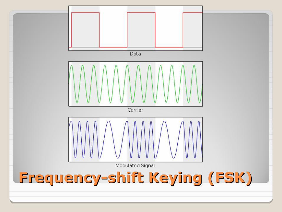
Frequency-shift Keying (FSK)Frequency-shift Keying (FSK)
A form of frequency modulation, otherwise known as FM. By causing and monitoring frequency changes in a signal sent over the phone line, two modem can sent information.
Frequency-shift Keying (FSK)Frequency-shift Keying (FSK)

Phase-shift Keying (PSK).Phase-shift Keying (PSK).
is a digital modulation scheme that conveys data by changing, or modulating, the phase of a reference signal (the carrier wave).

Quadrature amplitude modulation Quadrature amplitude modulation (QAM)(QAM)
conveys two analog message signals, or two digital bit streams, by changing (modulating) the amplitudes of two carrier waves, using the amplitude-shift keying (ASK) digital modulation scheme or amplitude modulation (AM) analog modulation scheme.

MODEMMODEM
All modem protocols since ITU V.34 (33.6Kbps maximum speed) up through the current ITU V.90 and ITU V.92 standards (56Kbps maximum speed) are full-duplex protocols.
ITU V.90 and V.92 protocols are the industry-standard protocols used today; V.92 support V.90.
Full-duplex : communications can travel in both directions at the same time and at the same speed.example: telephone call.
Half-duplex : communications can travel in both directions, but only one side can transmit at a time.example: radio call.

MODEMMODEM
V.90 V.90 is the ITU-T designation for a 56Kbps communication
standard. Reconciles the conflict between the proprietary U.S
Robotics (3Com) x2 and Rockwell K56flex modem specifications developed in 1996 and 1997.
The last ISA modems manufactured by major vendors typically support V.90, as do many PC Card and PCI modems built from 1998 to 2001.
V.92 Improved version of V.90 standard. Provide faster negotiation of the connection, call waiting
support and faster uploading than V.90. Most PCI and PC Card sold since mid-2001.
PROTOCOLS

MODEMMODEMMODEM NEGOTIATION
MODEMMODEM
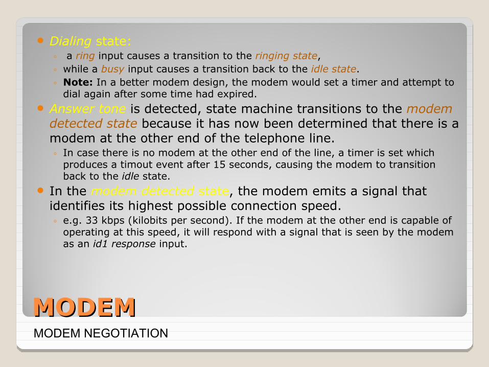
Dialing state:◦ a ring input causes a transition to the ringing state, ◦ while a busy input causes a transition back to the idle state. ◦ Note: In a better modem design, the modem would set a timer and attempt to
dial again after some time had expired. Answer tone is detected, state machine transitions to the modem
detected state because it has now been determined that there is a modem at the other end of the telephone line. ◦ In case there is no modem at the other end of the line, a timer is set which
produces a timout event after 15 seconds, causing the modem to transition back to the idle state.
In the modem detected state, the modem emits a signal that identifies its highest possible connection speed.◦ e.g. 33 kbps (kilobits per second). If the modem at the other end is capable of
operating at this speed, it will respond with a signal that is seen by the modem as an id1 response input.
MODEM NEGOTIATION

MODEMMODEM
If instead the timer expires, then the modem at the other end must not be capable of operating at 33 kbps, so the modem emits a different signal identifying a lower speed that it is capable of operating at, say 14.4 kbps.
When the far-end modem responds to any of the id signals, then the near end modem emits a training sequence.
Training sequence which is a pre-agreed signal that permits the modem at the far end to measure the impairments on the telephone channel and set up adaptive filters to compensate for these impairments. Then the modem at the far end responds by sending back a training sequence, which allows the near-end modem to set up its adaptive filters.
MODEM NEGOTIATION

MODEMMODEM
After both modems have set up their filters, a converged event causes the modem to transition to the connected state, in which data communication occurs. You can now start surfing the web.
Note: A better design would use a timeout timer so that if convergence does not occur, the modem tries to connect at a lower speed.
MODEM NEGOTIATION

MODEMMODEM
Modem Fails to Dial1. Check line and phone jacks on the modem. Use the line jack to attach the
modem to the telephone line. The phone jack takes the same RJ-11 silver cord cable, but it’s designed to let you daisy-chain a telephone to your modem, so you need only a single line for modem and telephone use. If you have reversed these cables, you will not get a dial tone.
2. If the cables are attached properly, check the cable for cuts or breaks. The outer jacket used on RJ-11 telephone cables is minimal. If the cable looks bad, replace it.
3. If the modem is external, make sure the RS-232 modem cable is running from the modem to a working serial port on your computer and that is switched on. Signal lights on the front of the modem can be used to determine whether the modem is on and whether it is responding to dialing commands.
PROBLEMS & TROUBLESHOOTING

MODEMMODEM
Modem Fails to Dial4. If the modem is a PC Card (PCMCIA card). Make sure it is fully plugged into the PCMCIA/PC
slot. With Windows 9x/Me/2000/XP, you should see a small PCMCIA/PC Card icon on the toolbar. Double click it to view the cards that are currently connected. If your modem is properly attached, it should be visible. Otherwise, remove it, reinsert it into the PCMCIA/PC Card slot, and see whether the computer detects it.
5. Make sure your modem has been properly configured by your OS. With Windows 9x/Me/2000, use the Modems control panel to view and test your modem configuration (with Windows XP, you can use the Modem Troubleshooter). Select your modem and click the diagnostics tab. This displays the COM (serial) ports in your computer. Select the COM port used by the modem, and click the More Info tab. This sends test signals to your modem. A properly working modem responds with information about the port and modem.
PROBLEMS & TROUBLESHOOTING

MODEMMODEM
Modem Fails to Dial6. If you get a Couldn’t Open Port error message, your modem
isn’t connected properly. It might be in use already by a program running in the background, or there might be an IRG or I/O port address conflict with another card in your computer. Whether you have a modem installed, every COM port that is working will display its IRQ, I/O port address and UART chip type when you run Diagnostics. The UART type should be 16550 or above for use with any modern modem.
PROBLEMS & TROUBLESHOOTING

MODEMMODEM
Computer Can’t Detect External Modem
1. Make sure the modem has been connected to the computer with the correct type of cable.
2. Make sure the COM (serial) port or USB port to which the modem is connected to is working.
3. Check the power cord and power switch.
PROBLEMS & TROUBLESHOOTING

MODEMMODEM
Using Your Modem Sound to Diagnose Your Modem
1. If you listen to your modem when it makes a connection, you might have realized that different types of modems make distinctive connection sounds and that different connection speeds also make distinctive sounds.
2. The various types of 56Kbps modems have distinctly different handshakes of tones, buzzes and warbles as they negotiate speeds with the ISP’s modem.
3. Check out www.modemsite.com/56k/trouble.asp (click handshake link) for find out sound samples of various modems during the handshaking process for troubleshooting.
PROBLEMS & TROUBLESHOOTING

ENDEND