Embed Size (px)
Citation preview

COMPUTERORGANIZATIONCHAPTER 5
5.4 SUBSYSTEMINTERCONNECTION
5.4 SUBSYSTEMINTERCONNECTION
In this section, explore how these three subsystems are interconnected.
The interconnection plays an important role because information needs to be exchanged between the three subsystems.
Connecting CPU and memory Connecting I/O devices Addressing input/output devices
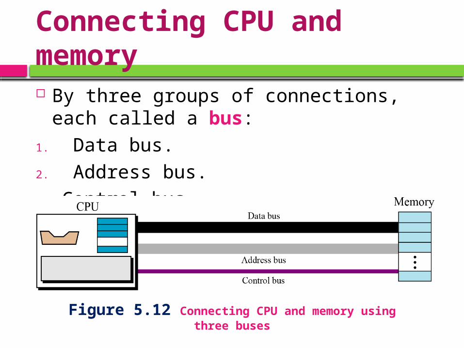
Connecting CPU and memory By three groups of connections, each
called a bus:1. Data bus.2. Address bus.3. Control bus.
Figure 5.12 Connecting CPU and memory using three buses
Connecting I/O devices
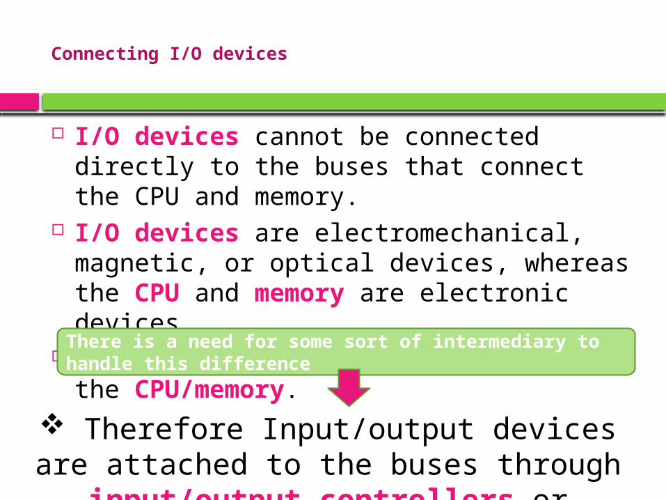
I/O devices cannot be connected directly to the buses that connect the CPU and memory.
I/O devices are electromechanical, magnetic, or optical devices, whereas the CPU and memory are electronic devices.
I/O devices much slower speed than the CPU/memory.
There is a need for some sort of intermediary to handle this difference
Therefore Input/output devices are attached to the buses through
input/output controllers or interfaces.
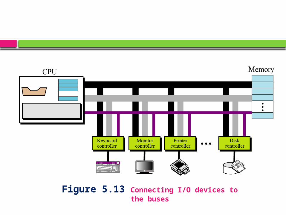
Figure 5.13 Connecting I/O devices to the buses
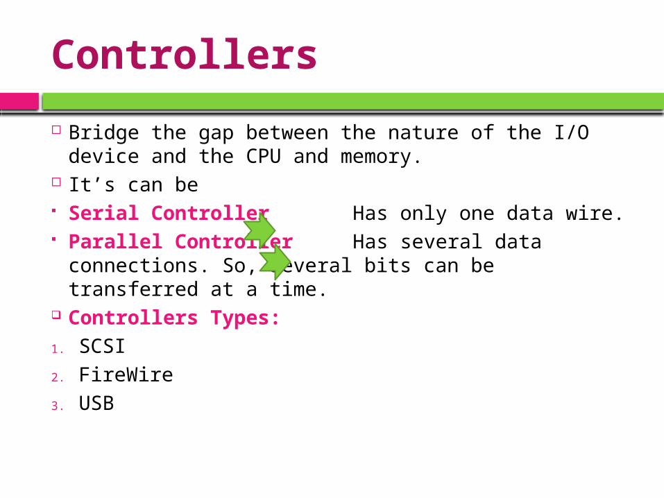
Controllers
Bridge the gap between the nature of the I/O device and the CPU and memory.
It’s can be Serial Controller Has only one data wire. Parallel Controller Has several data
connections. So, several bits can be transferred at a time.
Controllers Types:1. SCSI2. FireWire3. USB
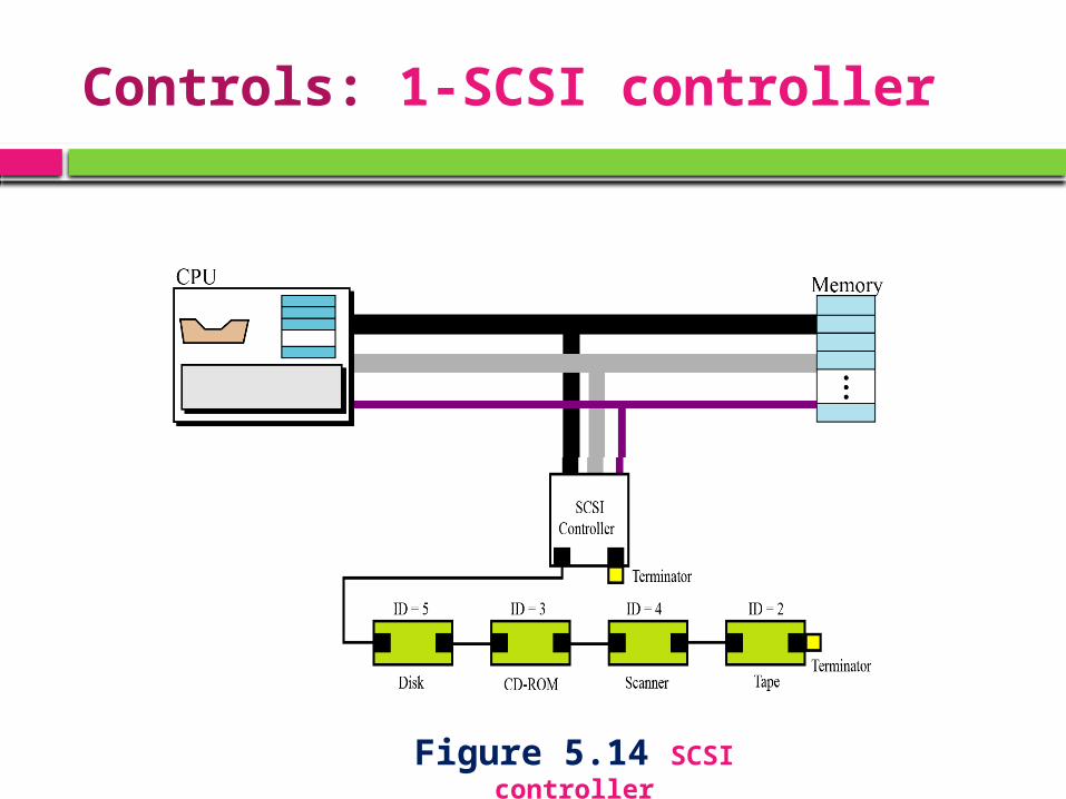
Controls: 1-SCSI controller
Figure 5.14 SCSI controller
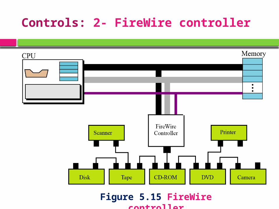
Controls: 2- FireWire controller
Figure 5.15 FireWire controller
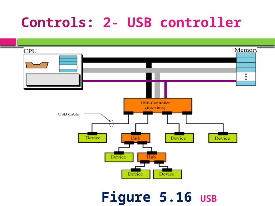
Controls: 2- USB controller
Figure 5.16 USB controller
Addressing input/outputdevices
The CPU usually uses the same bus to read data from or write data to main memory and I/O device.
The only difference is the instruction.
If the instruction refers to a word in main memory, data transfer is between main memory and the CPU.
If the instruction identifies an I/O device, data transfer is between the I/O device and the CPU.
Addressing input/outputdevices
Two methods for handling the addressing of I/O devices:
Isolated I/O Memory-mapped I/O.
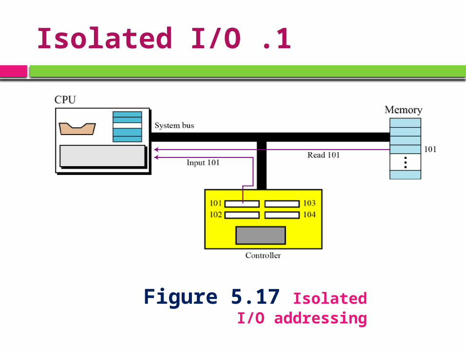
1 .Isolated I/O
Figure 5.17 Isolated I/O addressing
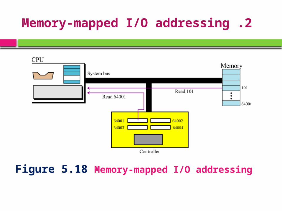
2 .Memory-mapped I/O addressing
Figure 5.18 Memory-mapped I/O addressing
5.5 PROGRAM EXECUTION
Description
Today, general-purpose computers use a set of instructions called a program to process data.
A computer executes the program to create output data from input data.
Both the program and the data are stored in memory.
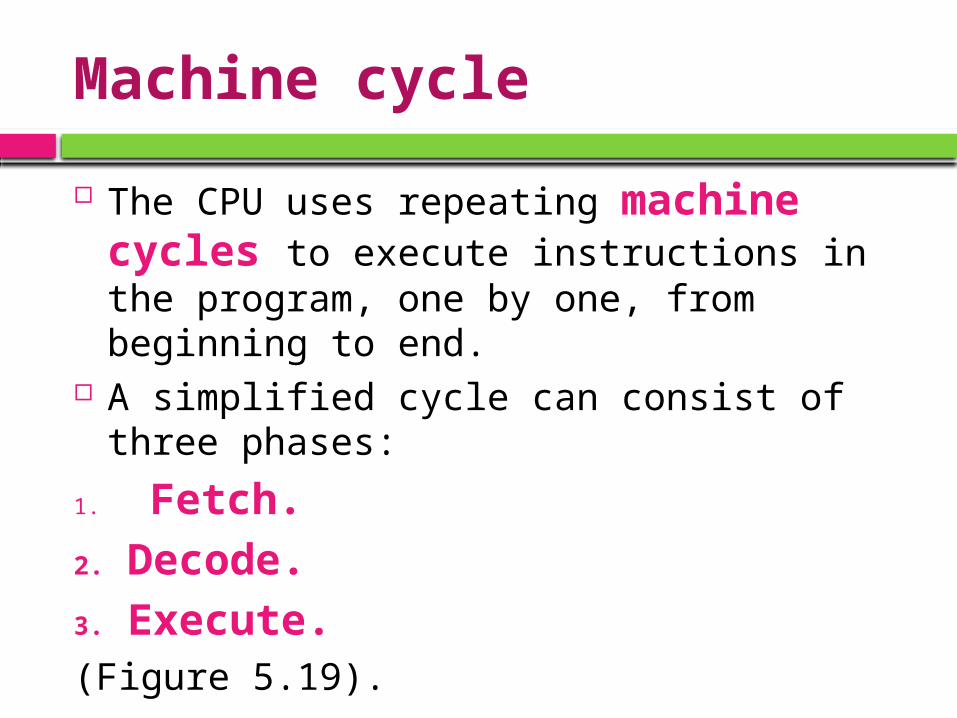
Machine cycle
The CPU uses repeating machine cycles to execute instructions in the program, one by one, from beginning to end.
A simplified cycle can consist of three phases:
1. Fetch. 2. Decode.3. Execute.(Figure 5.19).
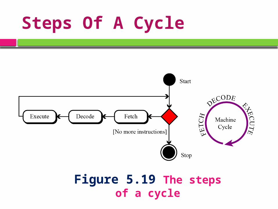
Steps Of A Cycle
Figure 5.19 The steps of a cycle
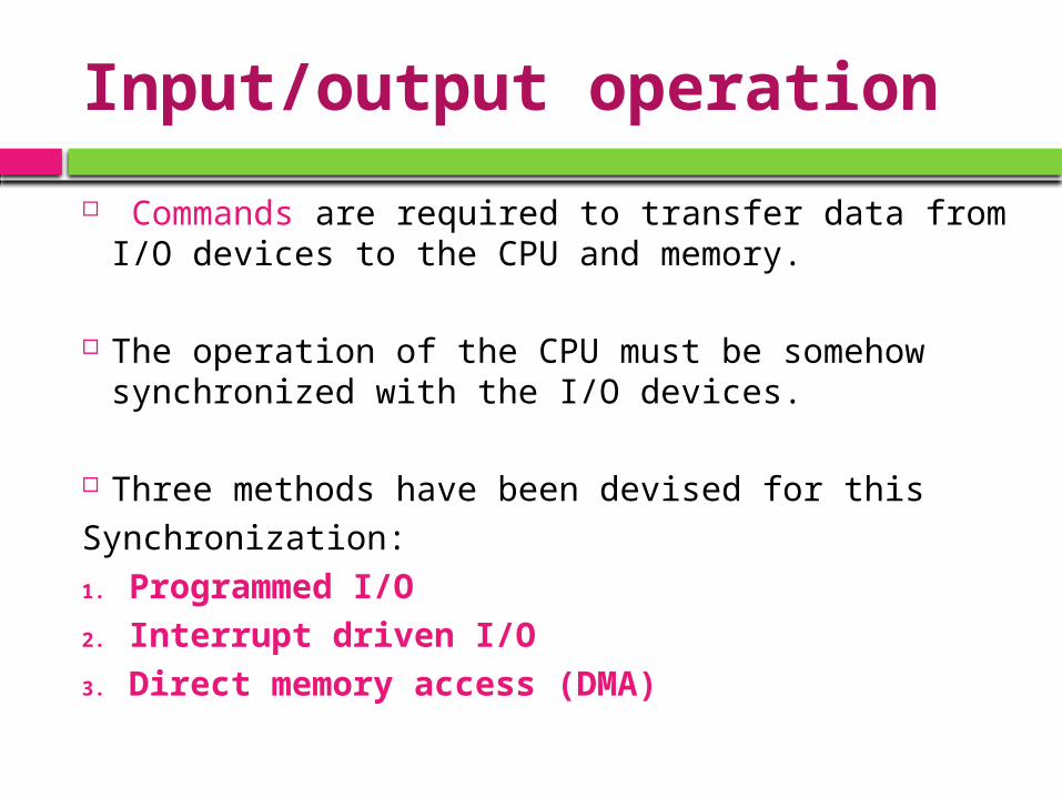
Input/output operation
Commands are required to transfer data from I/O devices to the CPU and memory.
The operation of the CPU must be somehow synchronized with the I/O devices.
Three methods have been devised for thisSynchronization:1. Programmed I/O2. Interrupt driven I/O3. Direct memory access (DMA)
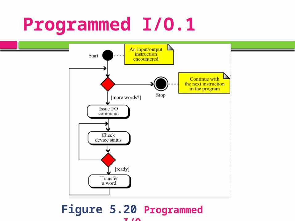
1.Programmed I/O
Figure 5.20 Programmed I/O
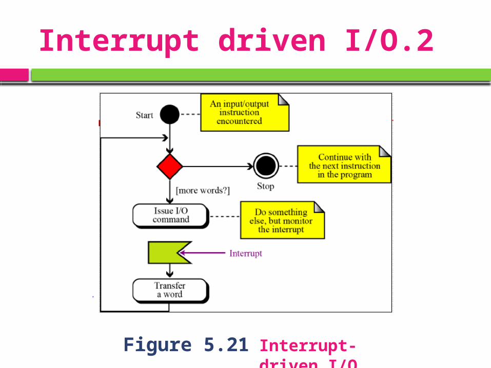
2.Interrupt driven I/O
Figure 5.21 Interrupt-driven I/O
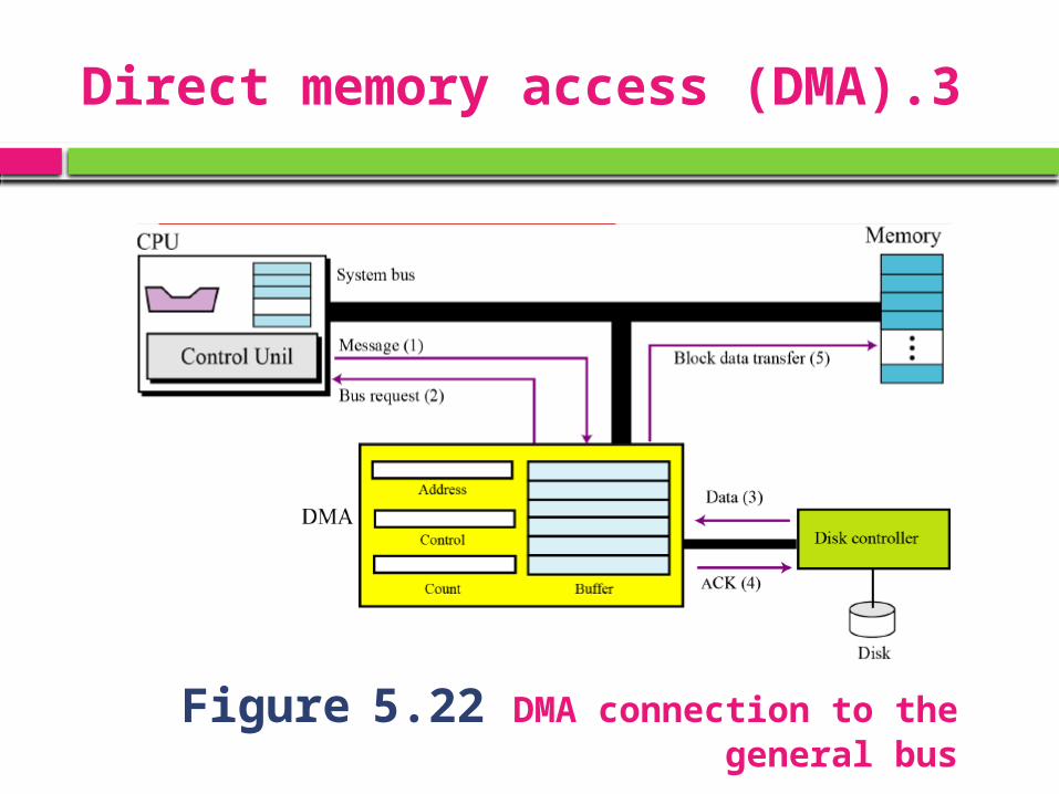
3.Direct memory access (DMA)
Figure 5.22 DMA connection to the general bus