Embed Size (px)
Citation preview
IP
1
1
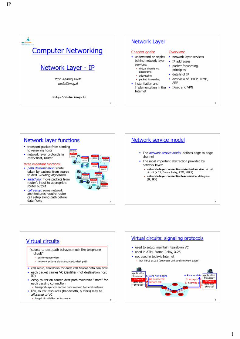
Computer Networking
Network Layer - IP
http://duda.imag.fr
Prof. Andrzej [email protected]
2
Network Layer
Chapter goals: understand principles
behind network layerservices: virtual circuits vs.
datagrams addressing packet forwarding
instantiation andimplementation in theInternet
Overview: network layer services IP addresses packet forwarding
principles details of IP overview of DHCP, ICMP,
ARP IPsec and VPN
3
Network layer functions transport packet from sending
to receiving hosts network layer protocols in
every host, router
three important functions: path determination: route
taken by packets from sourceto dest. Routing algorithms
switching: move packets fromrouter’s input to appropriaterouter output
call setup: some networkarchitectures require routercall setup along path beforedata flows
networkdata linkphysical
networkdata linkphysical
networkdata linkphysical
networkdata linkphysical
networkdata linkphysical
networkdata linkphysical
networkdata linkphysical
networkdata linkphysical
applicationtransportnetworkdata linkphysical
applicationtransportnetworkdata linkphysical
4
Network service model
The network service model defines edge-to-edgechannel
The most important abstraction provided bynetwork layer: network-layer connection-oriented service: virtual
circuit (X.25, Frame Relay, ATM, MPLS) network-layer connectionless service: datagram
(IP, IPX)
5
Virtual circuits
call setup, teardown for each call before data can flow each packet carries VC identifier (not destination host
ID) every router on source-dest path maintains “state” for
each passing connection transport-layer connection only involved two end systems
link, router resources (bandwidth, buffers) may beallocated to VC to get circuit-like performance
“source-to-dest path behaves much like telephonecircuit” performance-wise network actions along source-to-dest path
6
Virtual circuits: signaling protocols
used to setup, maintain teardown VC used in ATM, Frame-Relay, X.25 not used in today’s Internet
but MPLS at 2.5 (between Link and Network Layer)
applicationtransportnetworkdata linkphysical
applicationtransportnetworkdata linkphysical
1. Initiate call 2. incoming call3. Accept call4. Call connected
5. Data flow begins 6. Receive data
IP
2
7
Datagram networks: the Internetmodel no call setup at network layer routers: no state about end-to-end connections
no network-level concept of “connection”
packets typically routed using destination host ID packets between same source-dest pair may take different
paths
applicationtransportnetworkdata linkphysical
applicationtransportnetworkdata linkphysical
1. Send data 2. Receive data
8
Packet switching vs. Circuit switching
Eg. 1 Mbit link each user:
100 Kb/s when “active” active 10% of time
circuit-switching: 10 users
packet switching: with 35 users, probability > 10
active less that .004
Packet switching allows more users to use network!
N users1 Mbps link
9
The Internet Network layer
routingtable
Host, router network layer functions:
Routing protocols• route selection• RIP, OSPF, BGP
IP protocol• addressing conventions• datagram format• packet handling conventions
ICMP protocol• error reporting• router “signaling”
Transport layer: TCP, UDP
Link layer (PPP or LAN)
Physical layer
Networklayer
10
IP principles
Elements host = end system; router = intermediate system;
subnetwork = a collection of hosts that can communicatedirectly without routers
Routers are between subnetworks only: a subnetwork = a collection of systems with a common prefix
Packet forwarding direct: inside a subnetwork hosts communicate directly without
routers, router delivers packets to hosts indirect: between subnetworks one or several routers are used
Host either sends a packet to the destination using itsLAN, or it passes it to the router for forwarding
11
Interconnection structure - layer 3
host
router
switch(bridge)
interconnectionlayer 3
VLANsubnetwork 1 subnet 3
subnet 2
12
Interconnection at layer 3 Routers
interconnect subnetworks logically separate groups of hosts managed by one entity
Forwarding based on IP address structured address space routing tables: aggregation of entries works if no loops - routing protocols scalable inside one administrative domain
IP
3
13
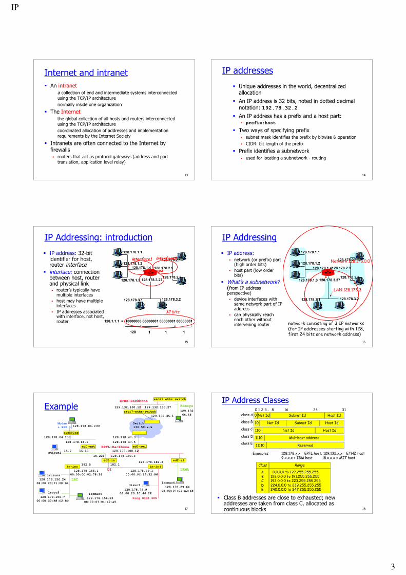
Internet and intranet An intranet
a collection of end and intermediate systems interconnectedusing the TCP/IP architecturenormally inside one organization
The Internetthe global collection of all hosts and routers interconnectedusing the TCP/IP architecturecoordinated allocation of addresses and implementationrequirements by the Internet Society
Intranets are often connected to the Internet byfirewalls routers that act as protocol gateways (address and port
translation, application level relay)
14
IP addresses
Unique addresses in the world, decentralizedallocation
An IP address is 32 bits, noted in dotted decimalnotation: 192.78.32.2
An IP address has a prefix and a host part: prefix:host
Two ways of specifying prefix subnet mask identifies the prefix by bitwise & operation CIDR: bit length of the prefix
Prefix identifies a subnetwork used for locating a subnetwork - routing
15
IP Addressing: introduction
IP address: 32-bitidentifier for host,router interface
interface: connectionbetween host, routerand physical link router’s typically have
multiple interfaces host may have multiple
interfaces IP addresses associated
with interface, not host,router
128.178.1.1
128.178.1.2
128.178.1.3
128.178.1.4 128.178.2.9
128.178.2.2
128.178.2.1
128.178.3.2128.178.3.1
128.178.3.27
128.1.1.1 = 10000000 00000001 00000001 00000001
128 1 11
32 bits
interface1 interface2
interface3
16
IP Addressing
IP address: network (or prefix) part
(high order bits) host part (low order
bits)
What’s a subnetwork?(from IP addressperspective) device interfaces with
same network part of IPaddress
can physically reacheach other withoutintervening router
128.178.1.1
128.178.1.2
128.178.1.3
128.178.1.4128.178.2.9
128.178.2.2
128.178.2.1
128.178.3.2128.178.3.1
128.178.3.27
network consisting of 3 IP networks(for IP addresses starting with 128, first 24 bits are network address)
LAN 128.178.3
Network 128.178.0.0
17
Example129.13266.46
129.132.100.12
lrcsuns128.178.156.24
08:00:20:71:0D:D4
lrcpc3128.178.156.7
00:00:C0:B8:C2:8D
in-inr128.178.156.1
00:00:0C:02:78:36128.178.79.1
00:00:0C:17:32:96
ed2-in182.1
in-inj128.178.182.3
182.5
128.178.100.3
LRC
15.221
Ring SIDI SUN
DI
ed0-swi15.13 128.178.100.12
128.178.84.1ed0-ext EPFL-Backbone
sic500cs128.178.84.130
Modem+ PPP
disun3128.178.79.9
08:00:20:20:46:2E
128.178.84.133
stisun1 15.7
128.178.47.5
128.178.47.3
Switch
ezci7-ethz-switch129.132.35.1
130.59.x.x
ed2-el
128.178.29.6408:00:07:01:a2:a5
LEMA
128.178.156.2308:00:07:01:a2:a5
ezci7-ethz-switch
Komsys ETHZ-Backbone
129.132.100.27
lrcmac4
lrcmac4
18
IP Address Classes
Examples: 128.178.x.x = EPFL host; 129.132.x.x = ETHZ host9.x.x.x = IBM host 18.x.x.x = MIT host
Class Range
ABCDE
0.0.0.0 to 127.255.255.255128.0.0.0 to 191.255.255.255192.0.0.0 to 223.255.255.255224.0.0.0 to 239.255.255.255240.0.0.0 to 247.255.255.255
Class B addresses are close to exhausted; newaddresses are taken from class C, allocated ascontinuous blocks
0 Net Id0 1 2 3… 8 16 24 31
10 Net Id
110 Net Id
1110 Multicast address
11110 Reserved
Subnet Id
Host Id
Host Id
class A
class B
class C
class D
class E
Host Id
Subnet Id
IP
4
19
Special case IP addresses
1. 0.0.0.0 this host, on this network2. 0.hostId specified host on this net (initialization phase)3. 255.255.255.255 limited broadcast (not forwarded by routers)4. subnetId.all 1’s broadcast on this subnet5. subnetId.all 0’s BSD used it for broadcast
on this subnet (obsolate)6. 127.x.x.x loopback
7. 10/8 reserved networks for 172.16/12 internal use (Intranet)
192.168/16
1,2: source IP@ only; 3,4,5: destination IP@ only20
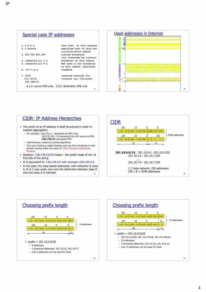
Used addresses in Internet
21
CIDR: IP Address Hierarchies
The prefix of an IP address is itself structured in order tosupport aggregation For example: 128.178.x.y represents an EPFL host
128.178.156 / 24 represents the LRC subnet at EPFL 128.178/15 represents EPFL
Used between routers by routing algorithms This way of doing is called classless and was first introduced in inter
domain routing under the name of CIDR (Classless InterdomainRouting)
Notation: 128.178.0.0/16 means : the prefix made of the 16first bits of the string
It is equivalent to: 128.178.0.0 with netmask=255.255.0.0 In the past, the class based addresses, with networks of class
A, B or C was used; now only the distinction between class Dand non-class D is relevant. 22
CIDR
1100 1001 0000 1010 0000 0000 0000 0000
1100 1001 0000 1010 0000 0111 1111 1111
201
201
10
10
0
7 255
0
2048 addresses
21 11
201.10.0.0/21: 201.10.0.0 - 201.10.0.255 201.10.1.0 - 201.10.1.255 ... 201.10.7.0 - 201.10.7.255
1 C class network: 256 addresses256 × 8 = 2048 addresses
23
Choosing prefix length
prefix = 201.10.0.0/29 8 addresses 2 broadcast addresses: 201.10.0.0, 201.10.0.7 only 6 addresses can be used for hosts
1100 1001 0000 1010 0000 0000 0000 0000
1100 1001 0000 1010 0000 0000 0000 0111
201
201
10
10
0
0 7
0
8 addresses
29 3
24
Choosing prefix length
prefix = 201.10.0.0/28 201.10.0.16/28, 201.10.0.32/28, 201.10.0.48/28… 16 addresses 2 broadcast addresses: 201.10.0.0, 201.10.0.15 only 14 addresses can be used for hosts
1100 1001 0000 1010 0000 0000 0000 0000
1100 1001 0000 1010 0000 0000 0000 1111
201
201
10
10
0
0 15
0
16 addresses
28 4
IP
5
25
Address allocation World coverage
Europe and the Middle East (RIPE NCC) Africa (ARIN & RIPE NCC) North America (ARIN) Latin America including the Caribbean (ARIN) Asia-Pacific (APNIC)
Current allocations of Class C 193-195/8, 212-213/8, 217/8 for RIPE 199-201/8, 204-209/8, 216/8 for ARIN 202-203/8, 210-211/8, 218/8 for APNIC
Simplifies routing short prefix aggregates many subnetworks routing decision is taken based on the short prefix
26
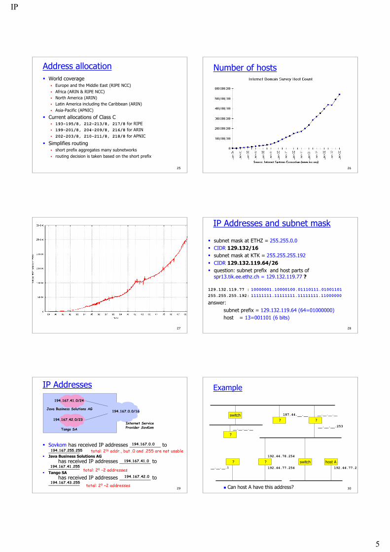
Number of hosts
27 28
IP Addresses and subnet mask
subnet mask at ETHZ = 255.255.0.0 CIDR 129.132/16 subnet mask at KTK = 255.255.255.192 CIDR 129.132.119.64/26 question: subnet prefix and host parts of
spr13.tik.ee.ethz.ch = 129.132.119.77 ?
129.132.119.77 : 10000001.10000100.01110111.01001101255.255.255.192: 11111111.11111111.11111111.11000000
answer:subnet prefix = 129.132.119.64 (64=01000000)host = 13=001101 (6 bits)
29
IP Addresses
Sovkom has received IP addresses ___________ to___________
Java Business Solutions AGhas received IP addresses ___________ to
___________ Tango SA
has received IP addresses ___________ to___________
194.167.0.0/16
Internet ServiceProvider SovKom
Java Business Solutions AG
Tango SA
194.167.41.0/24
194.167.42.0/23
194.167.255.255194.167.0.0
194.167.41.255194.167.41.0
194.167.42.0194.167.43.255
total: 216 addr., but .0 and .255 are not usable
total: 28 –2 addresses
total: 29 –2 addresses30
Example
switch ? ?
?
? switch host A
192.44.78.254
? 192.44.77.254 192.44.77.2__.__.__.1
__.__.__.__
187.44.__.__ __.__.__.__
__.__.__.253
Can host A have this address?
IP
6
31
Example
switchhost Y router
host X
router switch host A
192.44.78.254
host Z192.44.77.254 192.44.78.2192.44.77.1
187.44.1.2
187.44.1.1 187.44.1.254
192.44.78.253
Host A is on subnetwork 192.44.78 32
IP PrinciplesHomogeneous addressing an IP address is unique across the whole network ( = the world
in general) IP address is the address of the interface communication between IP hosts requires knowledge of IP
addresses
Routing: inside a subnetwork: hosts communicate directly without
routers between subnetworks: one or several routers are used a subnetwork = a collection of systems with a common prefix
33
destination@ subnetMask nextHop
DEFAULT 128.178.156.1
At lrcsuns: Next Hop Table
IP subnetMask
128.178.156.24 255.255.255.0
Physical Interface Tables
destination@ subnetMask nextHop
128.178.156.0DEFAULT
255.255.255.0128.178.182.5128.178.182.1
At in-inj: Next Hop Table
IP subnetMask
128.178.79.1128.178.182.3
255.255.255.0255.255.255.0
Physical Interface Tables
IP packet forwarding algorithm Rule for sending packets (hosts, routers)
if the destination IP address has the same prefix as one ofmy interfaces, send directly to that interface
otherwise send to a router as given by the IP routing table
34
Example129.13266.46
129.132.100.12
lrcsuns128.178.156.24
08:00:20:71:0D:D4
lrcpc3128.178.156.7
00:00:C0:B8:C2:8D
in-inr128.178.156.1
00:00:0C:02:78:36128.178.79.1
00:00:0C:17:32:96
ed2-in182.1
in-inj128.178.182.3
182.5
128.178.100.3
LRC
15.221
Ring SIDI SUN
DI
ed0-swi15.13 128.178.100.12
128.178.84.1ed0-ext EPFL-Backbone
sic500cs128.178.84.130
Modem+ PPP
disun3128.178.79.9
08:00:20:20:46:2E
128.178.84.133
stisun1 15.7
128.178.47.5
128.178.47.3
Switch
ezci7-ethz-switch129.132.35.1
130.59.x.x
ed2-el
128.178.29.6408:00:07:01:a2:a5
LEMA
128.178.156.2308:00:07:01:a2:a5
ezci7-ethz-switch
Komsys ETHZ-Backbone
129.132.100.27
lrcmac4
lrcmac4
35
IP packet forwarding algorithmdestAddr = packet dest. address, destinationAddr = address in routing
tableCase 1: a host route exists for destAddr
for every entry in routing tableif (destinationAddr = destAddr)then send to nextHop IPaddr; leave
Case 2: destAddr is on a directly connected network (= on-link):for every physical interface IP address A and subnet mask SM
if(A & SM = destAddr & SM)then send directly to destAddr; leave
Case 3: a network route exists for destAddr for every entry in routing table and subnet mask SM
if (destinationAddr & SM = destAddr & SM)then send to nextHop IP addr; leave
Case 4: use default routefor every entry in routing table
if (destinationAddr=DEFAULT) then send to nextHop IPaddr; leave 36
Getting a datagram from source to dest.
IP datagram:
128.178.1.1
128.178.1.2
128.178.1.3
128.178.1.4128.178.2.9
128.178.2.2
128.178.2.1
128.178.3.2128.178.3.1
128.178.3.27
A
BE
miscfields
sourceIP addr
destIP addr data
datagram remainsunchanged, as it travelssource to destination
addr fields of interest here
routing table in A
Dest. Net. next router Nhops128.178.1 1128.178.2 128.178.1.4 2128.178.3 128.178.1.4 2 default 128.178.1.4
to Internet
IP
7
37
Getting a datagram from source todest.: same subnetwork
128.178.1.1
128.178.1.2
128.178.1.3
128.178.1.4128.178.2.9
128.178.2.2
128.178.2.1
128.178.3.2128.178.3.1
128.178.3.27
A
BE
Starting at A, given IPdatagram addressed to B:
look up net. address of B find B is on same net. as A link layer will send datagram
directly to B inside link-layerframe B and A are directly
connected
Dest. Net. next router Nhops128.178.1 1128.178.2 128.178.1.4 2128.178.3 128.178.1.4 2
miscfields128.178.1.1 128.178.1.3 data
P
P
P P
default 128.178.1.4
to Internet
38
Getting a datagram from source todest.: different subnetworks
128.178.1.1
128.178.1.2
128.178.1.3
128.178.1.4128.178.2.9
128.178.2.2
128.178.2.1
128.178.3.2128.178.3.1
128.178.3.27
A
BE
Starting at A, dest. E: look up network address of E E on different network
A, E not directly attached routing table: next hop router to
E is 128.178.1.4 link layer sends datagram to
router 128.178.1.4 inside link-layer frame
datagram arrives at 128.178.1.4 continued…..
Dest. Net. next router Nhops128.178.1 1128.178.2 128.178.1.4 2128.178.3 128.178.1.4 2
miscfields128.178.1.1 128.178.2.3 data
P
P
P
default 128.178.1.4
to Internet
39
128.178.1.1
128.178.1.2
128.178.1.3
128.178.1.4128.178.2.9
128.178.2.2
128.178.2.1
128.178.3.2128.178.3.1
128.178.3.27
A
BE
Arriving at 128.178.1.4,destined for 128.178.2.2
look up network address of E E on same network as router’s
interface 128.178.2.9 router, E directly attached
link layer sends datagram to128.178.2.2 inside link-layer framevia interface 128.178.2.9
datagram arrives at 128.178.2.2!!!(hooray!)
network router Nhops interface128.178.1 - 1 128.178.1.4 128.178.2 - 1 128.178.2.9128.178.3 - 1 128.178.3.27
Dest. next
Getting a datagram from source todest.: different subnetworks
miscfields128.178.1.1 128.178.2.3 data
P
P
P
P
default xx xx
40
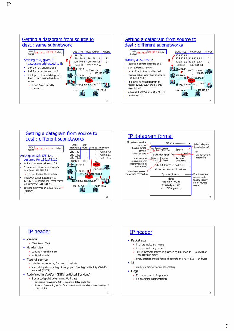
IP datagram format
ver length
32 bits
data (variable length,typically a TCP
or UDP segment)
16-bit identifierInternet
checksumtime to
live
32 bit source IP address
IP protocol versionnumber
header length (bytes)
max numberremaining hops
(decremented at each router)
forfragmentation/reassembly
total datagramlength (bytes)
upper layer protocolto deliver payload to
head.len
type ofservice
“type” of data flgs fragment offset
upper layer
32 bit destination IP address
Options (if any) E.g. timestamp,record routetaken, specifylist of routers to visit.
41
IP header Version
IPv4, futur IPv6
Header size options - variable size in 32 bit words
Type of service priority : 0 - normal, 7 - control packets short delay (telnet), high throughput (ftp), high reliability (SNMP),
low cost (NNTP)
Redefined in DiffServ (Differentiated Services) 1 byte codepoint determining QoS class
Expedited Forwarding (EF) - minimize delay and jitter Assured Forwarding (AF) - four classes and three drop-precedences (12
codepoints)
42
IP header Packet size
in bytes including header in bytes including header <= 64 Kbytes; limited in practice by link-level MTU (Maximum
Transmission Unit) every subnet should forward packets of 576 = 512 + 64 bytes
Id unique identifier for re-assembling
Flags M : more ; set in fragments F : prohibits fragmentation
IP
8
43
IP header Offset
position of a fragment in multiples of 8 bytes
TTL (Time-to-live) in secondes now: number of hops router : --, if 0, drop (send ICMP packet to source)
Protocol identifier of protocol (1 - ICMP, 6 - TCP, 17 - UDP)
Checksum only on the header
44
IP header Options
strict source routing all routers
loose source routing some routers
record route timestamp route router alert
used by IGMP or RSVP for processing a packet
45
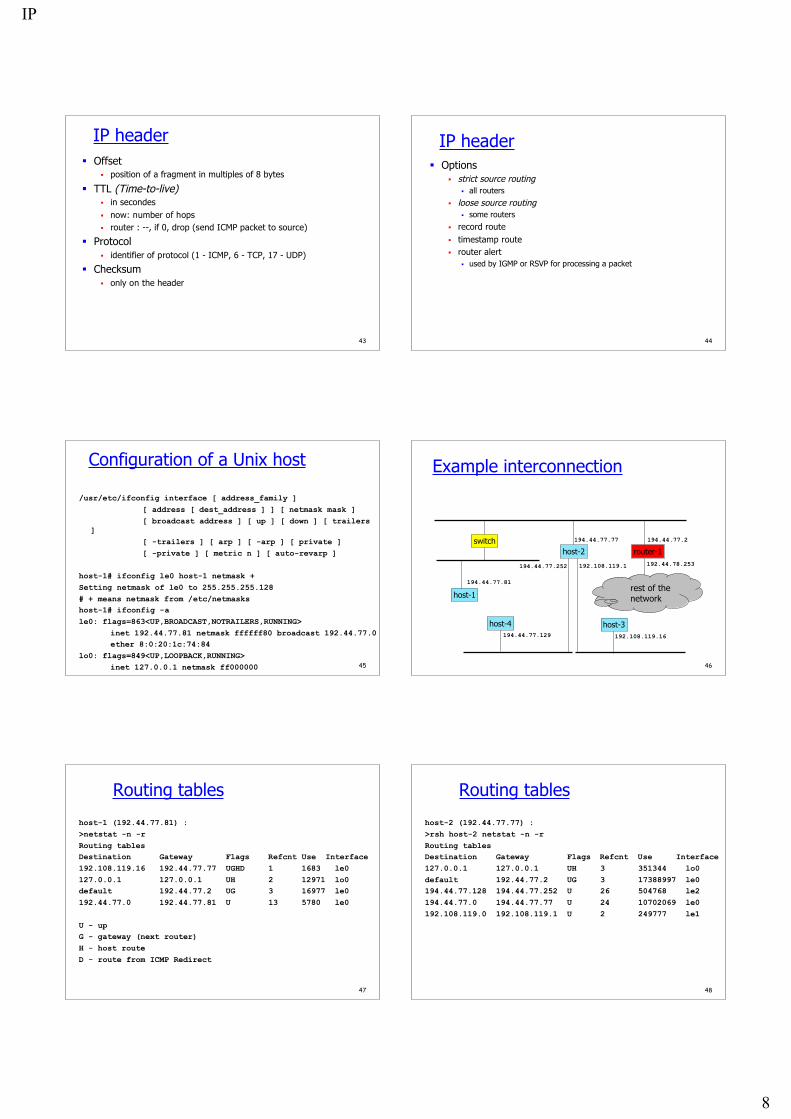
Configuration of a Unix host
/usr/etc/ifconfig interface [ address_family ][ address [ dest_address ] ] [ netmask mask ][ broadcast address ] [ up ] [ down ] [ trailers
][ -trailers ] [ arp ] [ -arp ] [ private ][ -private ] [ metric n ] [ auto-revarp ]
host-1# ifconfig le0 host-1 netmask +Setting netmask of le0 to 255.255.255.128# + means netmask from /etc/netmaskshost-1# ifconfig -ale0: flags=863<UP,BROADCAST,NOTRAILERS,RUNNING>
inet 192.44.77.81 netmask ffffff80 broadcast 192.44.77.0ether 8:0:20:1c:74:84
lo0: flags=849<UP,LOOPBACK,RUNNING>inet 127.0.0.1 netmask ff000000 46
Example interconnection
switchhost-2 router-1
host-1
194.44.77.81
194.44.77.77 194.44.77.2
192.44.78.253
rest of thenetwork
192.108.119.1
host-3192.108.119.16
host-4194.44.77.129
194.44.77.252
47
Routing tables
host-1 (192.44.77.81) :>netstat -n -rRouting tablesDestination Gateway Flags Refcnt Use Interface192.108.119.16 192.44.77.77 UGHD 1 1683 le0127.0.0.1 127.0.0.1 UH 2 12971 lo0default 192.44.77.2 UG 3 16977 le0192.44.77.0 192.44.77.81 U 13 5780 le0
U - upG - gateway (next router)H - host routeD - route from ICMP Redirect
48
Routing tables
host-2 (192.44.77.77) :>rsh host-2 netstat -n -rRouting tablesDestination Gateway Flags Refcnt Use Interface127.0.0.1 127.0.0.1 UH 3 351344 lo0default 192.44.77.2 UG 3 17388997 le0194.44.77.128 194.44.77.252 U 26 504768 le2194.44.77.0 194.44.77.77 U 24 10702069 le0192.108.119.0 192.108.119.1 U 2 249777 le1
IP
9
49
Modifying routing tables
/usr/etc/route [ -fn ] add|delete [ host|net ]destination [gateway [ metric ] ]
host-1# netstat -rRouting tablesDestination Gateway Flags Refcnt Use
Interfacelocalhost localhost UH 2 13569 lo0192.44.77.0 host-1 U 18 13272 le0host-1# ping 133.11.11.11sendto: Network is unreachablehost-1# route add 0.0.0.0 router-1 1add net 0.0.0.0 gateway router-1
50
Modifying routing tables
host-1# netstat -rRouting tablesDestination Gateway Flags Refcnt Use
Interfacelocalhost localhost UH 2 13591 lo0default router-1 UG 0 0 le0192.44.77.0 host-1 U 16 13566 le0host-1# ping 133.11.11.11133.11.11.11 is alive
51
IP Broadcasting, Multicasting Broadcast = send to all
sent to all hosts on one net/subnet; used by NetBIOS fordiscovery
Multicast = send to a group IP multicast address = class D = 224.0.0.0 to
239.255.255.255224.0.0.1 = all multicast capable systems on subnet224.0.0.2 = all multicast capable routers on subnet
used for: routing, conferencing, radio distribution, …
IP uses open group paradigm multicast IP addresses are logical (= non topological) for receiving data sent to multicast address m, a host must
subscribe to m for sending to multicast address m, a host simply put m in
the dest addr field52
IP Multicast Principles
R5R1
R2
R4
R3
A
B
SIGMP: join mMulticast Routing
to m
hosts subscribe via IGMP join messages sent torouter
routers build distribution tree via multicast routing sources do not know their destinations packet replication is done by routers
12
3
45
5
3
53
IP Multicast ForwardingAlgorithm
Systems have to know which group they belong to Hosts: application processes register to IP Routers: learn if members present with IGMP
Direct send to link layer: algorithmic mapping of 23 last bits : ex : 224.2.166.207 -> 01-00-5E-02-A6-CF
Read address MA = destination IP@
/* assume it is multicast */for every physical interface PI
if MA is enabled on PI thensend directly to PI
send directly(MA, MAC@): map last 23 bits of MA to last 23 bits of MAC address send MAC frame with DA = 01-00-5E-xx-xx-xx,
SA = own i/f address
Packet Forwarding (host, router)
Send directly (Ethernet)
IP subnetMask
128.178.156.24224.2.166.207224.2.127.255
255.255.255.0
At lrcsuns: Physical Interface Tables
54
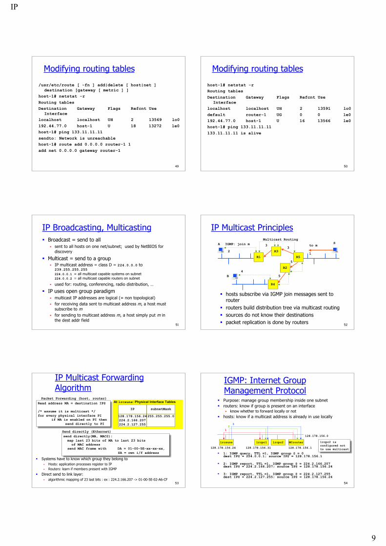
lrcsuns lrcpc1 lrcpc2 MCrouter
12
128.178.156.0
3
128.178.156.24 128.178.156.31 128.178.156.1
lrcpc2 is configured not to use multicast
IGMP: Internet GroupManagement Protocol
Purpose: manage group membership inside one subnet routers: know if group is present on an interface
know whether to forward locally or not hosts: know if a multicast address is already in use locally
1: IGMP query, TTL =1, IGMP group @ = 0dest IP@ = 224.0.0.1; source IP@ = 128.178.156.1
2: IGMP report, TTL =1, IGMP group @ = 224.2.166.207dest IP@ = 224.2.166.207; source IP@ = 128.178.156.24
3: IGMP report, TTL =1, IGMP group @ = 224.2.127.255dest IP@ = 224.2.127.255; source IP@ = 128.178.156.24
IP
10
55
IGMP Host ImplementationHost Implementation goal: avoid avalanche effects - one router
originated query might cause a burst of reports solution = synchronization avoidance protocol
1. hosts delay responses randomly 2. hosts listen to responses, only first one answers
MulticastAddressnot used
TimerActive Member
join group: (1)send response
leave group:
leave group:
response read:
timer expires:send responsequery read: (2)
event:action
Host IGMP Finite State Machine
56
DHCP
DHCP Dynamic Host Configuration Protocol (RFC 2131)
Goal: allow host to dynamically obtain its IP addressfrom network server when it joins network Support for mobile users who want to join network Allows reuse of addresses (hold address only while
connected)
Uses UDP port 67 (to server) and 68 (to client) IP source address 0, broadcast 255.255.255.255
57
DHCP
Dynamic addresses 2 databases
Static DB - Matches IP’s and Physical Addresses Dynamic DB - Pool of IP’s leased out
Temporary addresses Addresses leased from Dynamic DB are temporary Each lease has an expiration which the client must obey Can renew its lease on address in use
58
DHCP
Internet
Router192.168.1.1
DHCP Server192.168.1.2
DNS192.168.1.3
File Server192.168.1.4
Configinfo
ee:34:d6:75:03:e2
What’s my IP? What’s my subnet mask? Who’s my default router? Who’s my DNS?
arriving client
59
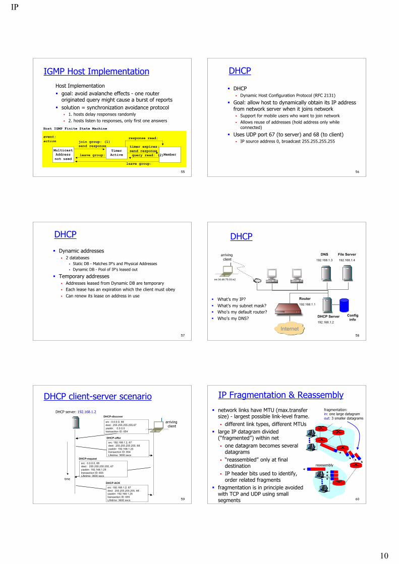
DHCP client-server scenario
DHCP server: 192.168.1.2
arriving client
time
DHCP-discover
src : 0.0.0.0, 68dest.: 255.255.255.255,67yiaddr: 0.0.0.0transaction ID: 654
DHCP-offer
src: 192.168.1.2, 67dest: 255.255.255.255, 68yiaddrr: 192.168.1.25transaction ID: 654Lifetime: 3600 secs
DHCP-request
src: 0.0.0.0, 68dest:: 255.255.255.255, 67yiaddrr: 192.168.1.25transaction ID: 655Lifetime: 3600 secs
DHCP-ACK
src: 192.168.1.2, 67dest: 255.255.255.255, 68yiaddrr: 192.168.1.25transaction ID: 655Lifetime: 3600 secs 60
IP Fragmentation & Reassembly
network links have MTU (max.transfersize) - largest possible link-level frame. different link types, different MTUs
large IP datagram divided(“fragmented”) within net one datagram becomes several
datagrams “reassembled” only at final
destination IP header bits used to identify,
order related fragments fragmentation is in principle avoided
with TCP and UDP using smallsegments
fragmentation: in: one large datagramout: 3 smaller datagrams
reassembly
IP
11
61
MTU: Maximum Transfer Unit
Data links have differentmaximum packet length
MTU (maximum transmissionunit) = maximum packet sizeusable for an IP packet
value of short MTU ? of longMTU ?
Link technology MTU
Ethernet802.3 with LLC/SNAP
FDDIX.25
Frame RelayATM with AAL5
HyperchannelPPP
1500149243525761600918065535296 to1500
lrcsuns$ ifconfig -alo0: flags=849<UP,LOOPBACK,RUNNING,MULTICAST> mtu 8232 inet 127.0.0.1 netmask ff000000le0: flags=863<UP,BROADCAST,NOTRAILERS,RUNNING,MULTICAST> mtu 1500 inet 128.178.156.24 netmask ffffff00 broadcast 128.178.156.255 ether 8:0:20:71:d:d4
62
IP fragmentationIP hosts or routers may have IP datagrams larger than MTU fragmentation is performed when IP datagram too large re-assembly is only at destination fragmentation is in principle avoided with TCP
R2R1
MTU = 1500 MTU = 620 MTU =1500
IPHeader 1400 Bytes IP
Header 600 B
IPHeader 600 B
IPHeader 200 B
IPHeader 600 B
IPHeader 600 B
IPHeader 200 B
1 2a
2b
2c
3a
3b
3c
63
IP fragmentation IP datagram is fragmented if
MTU of interface < datagram total length all fragments are self-contained IP packets fragmentation controlled by fields: Identification, Flag and
Fragment Offset IP datagram = original ; IP packet = fragments or
complete datagram
Fragment data size (here 600) is always a multiple of 8Identification given by source
LengthIdentification
More Fragment flagOffset
8 * Offset
1
1420567000
2a
620567100
2b
620567175600
2c
2205670
1501200
64
TCP, UDP and fragmentation The UDP service interface accepts a datagram up to 64 KB
UDP datagram passed to the IP service interface as one SDU is fragmented at the source if resulting IP datagram is too large
The TCP service interface is stream oriented packetization is done by TCP several calls to the TCP service interface may be grouped into one
TCP segment (many small pieces) or: one call may cause several segments to be created (one large
piece) TCP always creates a segment that fits in one IP packet: no
fragmentation at source fragmentation may occur in a router, if IPv4 is used, and if PMTU
discovery is not implemented
65
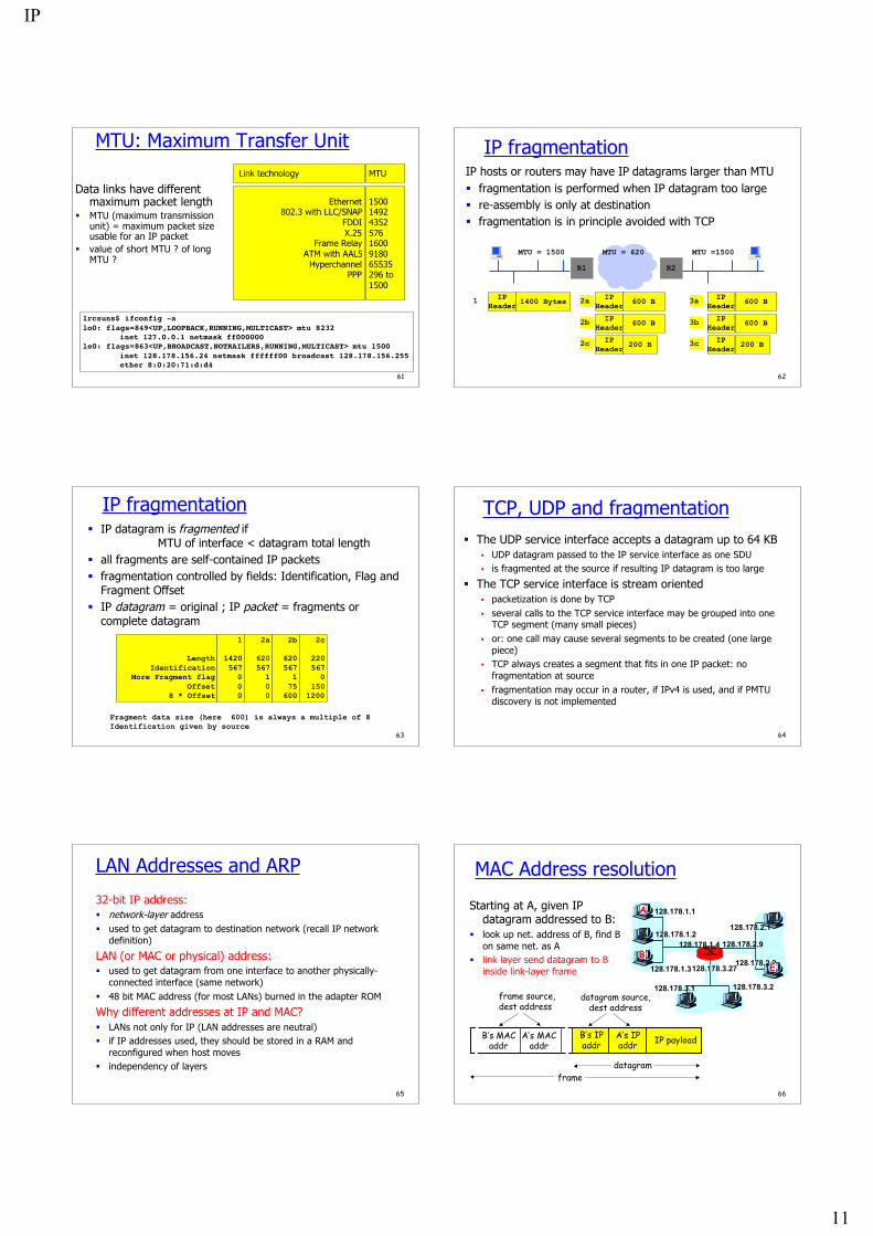
LAN Addresses and ARP
32-bit IP address: network-layer address used to get datagram to destination network (recall IP network
definition)
LAN (or MAC or physical) address: used to get datagram from one interface to another physically-
connected interface (same network) 48 bit MAC address (for most LANs) burned in the adapter ROM
Why different addresses at IP and MAC? LANs not only for IP (LAN addresses are neutral) if IP addresses used, they should be stored in a RAM and
reconfigured when host moves independency of layers
66
MAC Address resolution
128.178.1.1
128.178.1.2
128.178.1.3
128.178.1.4 128.178.2.9
128.178.2.2
128.178.2.1
128.178.3.2128.178.3.1
128.178.3.27
A
BE
Starting at A, given IPdatagram addressed to B:
look up net. address of B, find Bon same net. as A
link layer send datagram to Binside link-layer frame
B’s MACaddr
A’s MACaddr
B’s IPaddr
A’s IPaddr IP payload
datagramframe
frame source,dest address
datagram source,dest address
IP
12
67
Example
bridgehost Y router
host X
router bridge host A
192.44.78.254
host Z192.44.77.254 192.44.78.2192.44.77.1
187.44.1.2
187.44.1.1 187.44.1.254
192.44.78.253
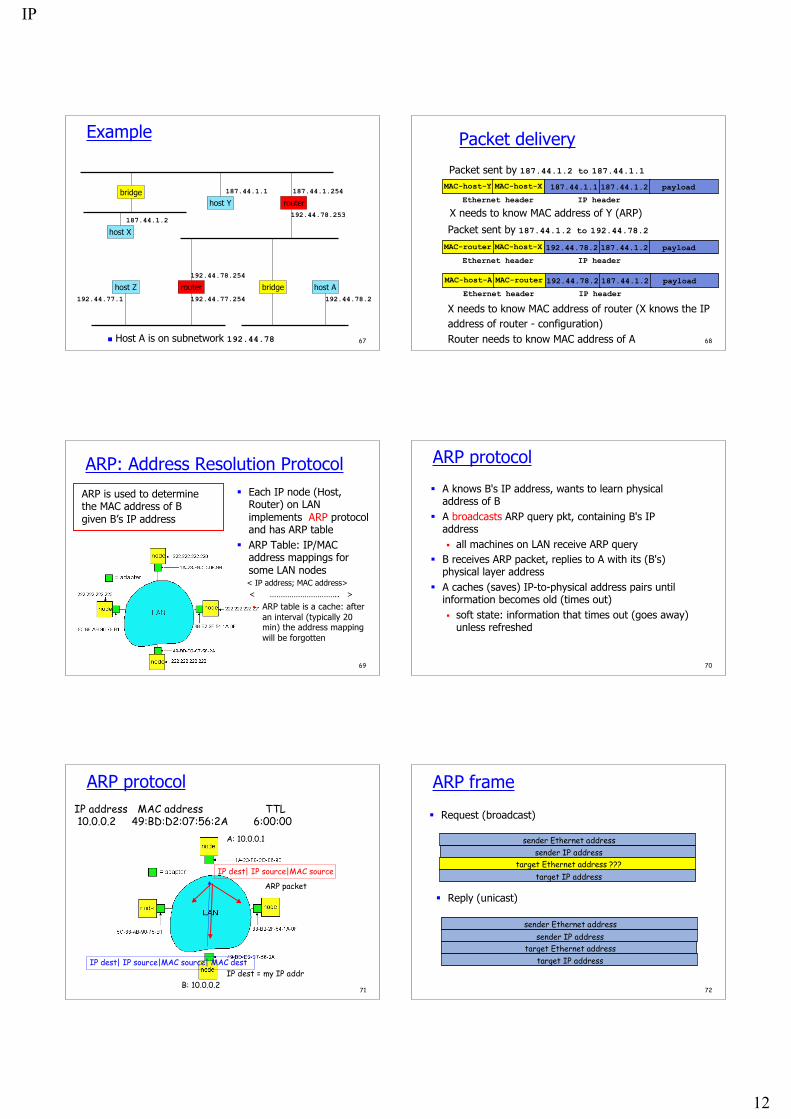
Host A is on subnetwork 192.44.78 68
Packet delivery
Packet sent by 187.44.1.2 to 187.44.1.1
187.44.1.1 187.44.1.2MAC-host-XMAC-host-Y payload
IP headerEthernet header
Packet sent by 187.44.1.2 to 192.44.78.2
192.44.78.2 187.44.1.2MAC-host-XMAC-router payload
IP headerEthernet header
192.44.78.2 187.44.1.2MAC-routerMAC-host-A payload
IP headerEthernet header
X needs to know MAC address of Y (ARP)
X needs to know MAC address of router (X knows the IPaddress of router - configuration)Router needs to know MAC address of A
69
ARP: Address Resolution Protocol Each IP node (Host,
Router) on LANimplements ARP protocoland has ARP table
ARP Table: IP/MACaddress mappings forsome LAN nodes
< IP address; MAC address> < ………………………….. >
ARP table is a cache: afteran interval (typically 20min) the address mappingwill be forgotten
ARP is used to determinethe MAC address of Bgiven B’s IP address
70
ARP protocol
A knows B's IP address, wants to learn physicaladdress of B
A broadcasts ARP query pkt, containing B's IPaddress all machines on LAN receive ARP query
B receives ARP packet, replies to A with its (B's)physical layer address
A caches (saves) IP-to-physical address pairs untilinformation becomes old (times out) soft state: information that times out (goes away)
unless refreshed
71
ARP protocolIP address MAC address TTL 10.0.0.2 49:BD:D2:07:56:2A 6:00:00
A: 10.0.0.1
B: 10.0.0.2
IP dest| IP source|MAC source
ARP packet
IP dest = my IP addrIP dest| IP source|MAC source| MAC dest
72
ARP frame
Request (broadcast)
sender IP addresssender Ethernet address
target IP addresstarget Ethernet address ???
sender IP addresssender Ethernet address
target IP addresstarget Ethernet address
Reply (unicast)
IP
13
73
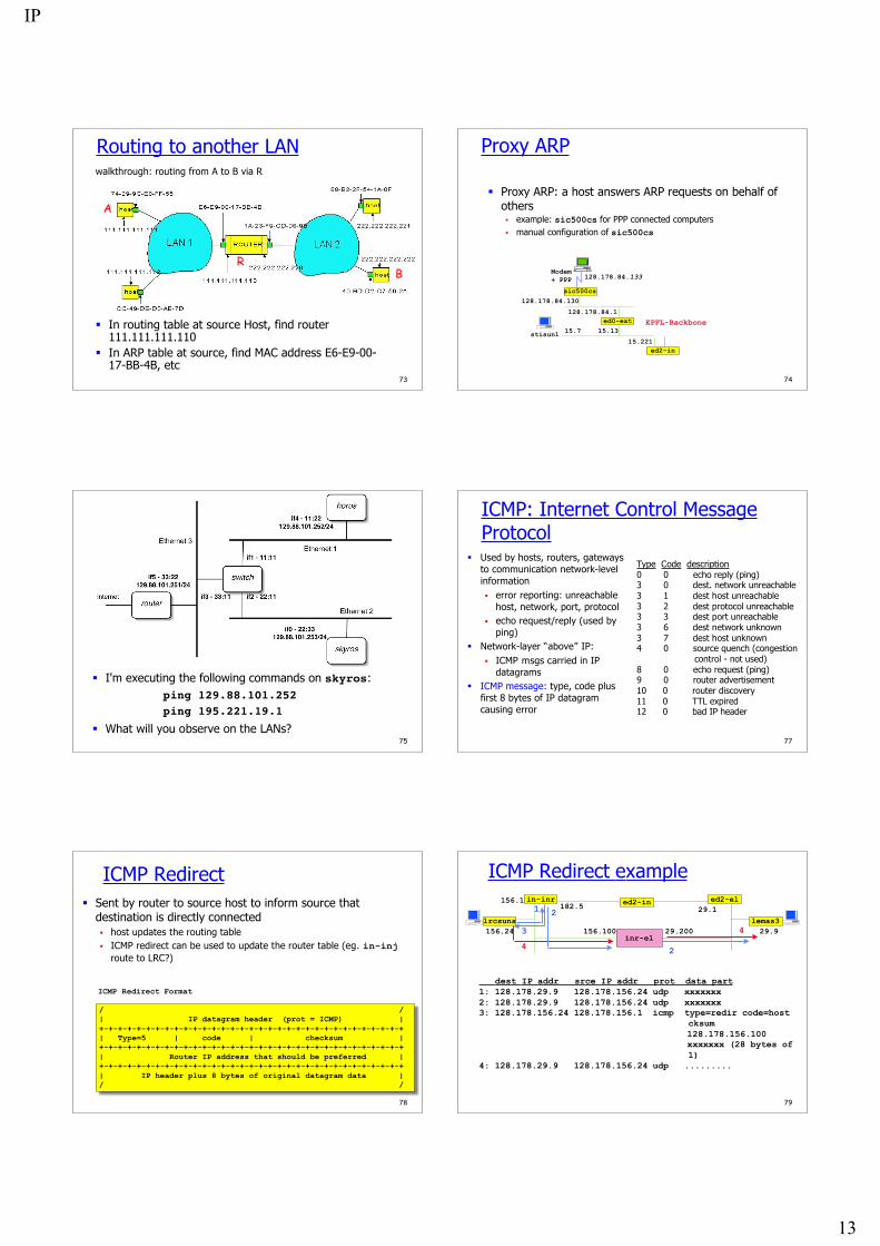
Routing to another LANwalkthrough: routing from A to B via R
In routing table at source Host, find router111.111.111.110
In ARP table at source, find MAC address E6-E9-00-17-BB-4B, etc
A
RB
74
Proxy ARP
Proxy ARP: a host answers ARP requests on behalf ofothers example: sic500cs for PPP connected computers manual configuration of sic500cs
ed2-in15.221
15.13
128.178.84.1ed0-ext EPFL-Backbone
sic500cs128.178.84.130
Modem+ PPP 128.178.84.133
stisun1 15.7
75
Question
I'm executing the following commands on skyros:ping 129.88.101.252ping 195.221.19.1
What will you observe on the LANs?77
ICMP: Internet Control MessageProtocol
Used by hosts, routers, gatewaysto communication network-levelinformation error reporting: unreachable
host, network, port, protocol echo request/reply (used by
ping) Network-layer “above” IP:
ICMP msgs carried in IPdatagrams
ICMP message: type, code plusfirst 8 bytes of IP datagramcausing error
Type Code description0 0 echo reply (ping)3 0 dest. network unreachable3 1 dest host unreachable3 2 dest protocol unreachable3 3 dest port unreachable3 6 dest network unknown3 7 dest host unknown4 0 source quench (congestion control - not used)8 0 echo request (ping)9 0 router advertisement10 0 router discovery11 0 TTL expired12 0 bad IP header
78
Sent by router to source host to inform source thatdestination is directly connected host updates the routing table ICMP redirect can be used to update the router table (eg. in-inj
route to LRC?)
ICMP Redirect
/ /| IP datagram header (prot = ICMP) |+-+-+-+-+-+-+-+-+-+-+-+-+-+-+-+-+-+-+-+-+-+-+-+-+-+-+-+-+-+-+-+-+| Type=5 | code | checksum |+-+-+-+-+-+-+-+-+-+-+-+-+-+-+-+-+-+-+-+-+-+-+-+-+-+-+-+-+-+-+-+-+| Router IP address that should be preferred |+-+-+-+-+-+-+-+-+-+-+-+-+-+-+-+-+-+-+-+-+-+-+-+-+-+-+-+-+-+-+-+-+| IP header plus 8 bytes of original datagram data |/ /
ICMP Redirect Format
79
ICMP Redirect example
lrcsuns
in-inr156.1182.5
156.24 156.100
1
4
4
dest IP addr srce IP addr prot data part1: 128.178.29.9 128.178.156.24 udp xxxxxxx2: 128.178.29.9 128.178.156.24 udp xxxxxxx3: 128.178.156.24 128.178.156.1 icmp type=redir code=host
cksum 128.178.156.100 xxxxxxx (28 bytes of
1)4: 128.178.29.9 128.178.156.24 udp .........
3
2
2lemas3
29.1ed2-el
inr-el29.929.200
ed2-in
IP
14
80
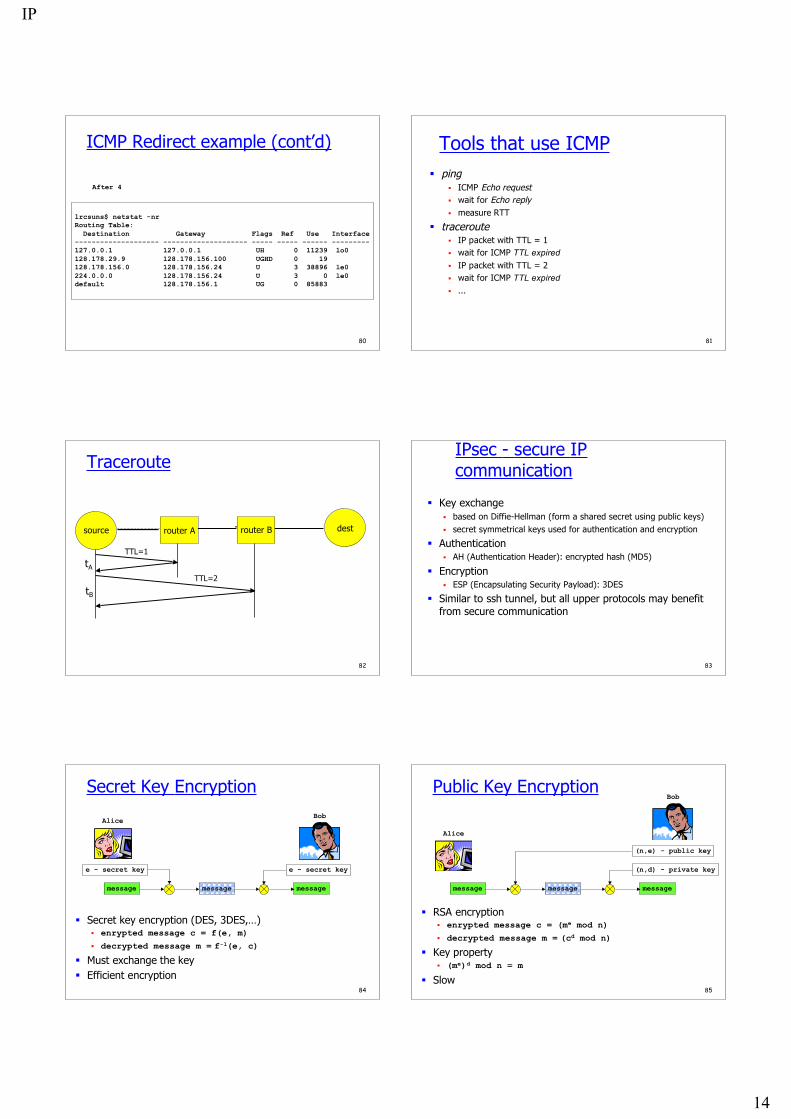
ICMP Redirect example (cont’d)
lrcsuns$ netstat -nrRouting Table: Destination Gateway Flags Ref Use Interface-------------------- -------------------- ----- ----- ------ ---------127.0.0.1 127.0.0.1 UH 0 11239 lo0128.178.29.9 128.178.156.100 UGHD 0 19 128.178.156.0 128.178.156.24 U 3 38896 le0224.0.0.0 128.178.156.24 U 3 0 le0default 128.178.156.1 UG 0 85883
After 4
81
Tools that use ICMP ping
ICMP Echo request wait for Echo reply measure RTT
traceroute IP packet with TTL = 1 wait for ICMP TTL expired IP packet with TTL = 2 wait for ICMP TTL expired ...
82
Traceroute
source
tA
tB
router A router B dest
TTL=1
TTL=2
83
IPsec - secure IPcommunication
Key exchange based on Diffie-Hellman (form a shared secret using public keys) secret symmetrical keys used for authentication and encryption
Authentication AH (Authentication Header): encrypted hash (MD5)
Encryption ESP (Encapsulating Security Payload): 3DES
Similar to ssh tunnel, but all upper protocols may benefitfrom secure communication
84
Secret Key Encryption
message
Secret key encryption (DES, 3DES,…) enrypted message c = f(e, m)
decrypted message m = f-1(e, c)
Must exchange the key Efficient encryption
message message
e - secret key
BobAlice
e - secret key
85
Public Key Encryption
message
RSA encryption enrypted message c = (me mod n)
decrypted message m = (cd mod n)
Key property (me)d mod n = m
Slow
message message
(n,e) - public key
(n,d) - private key
Bob
Alice
IP
15
86
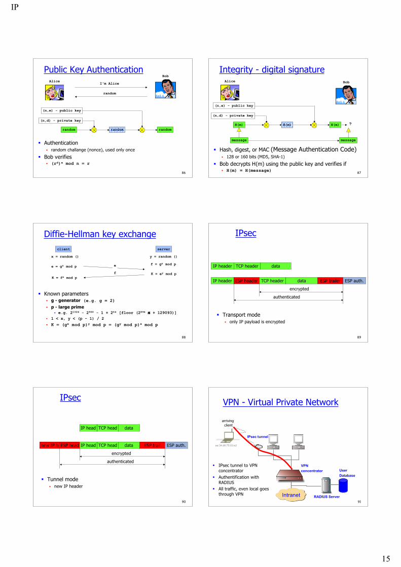
Public Key Authentication
random
Authentication random challange (nonce), used only once
Bob verifies (rd)e mod n = r
random random
(n,e) - public key
(n,d) - private key
BobAlice
I'm Alice
random
87
Integrity - digital signature
H(m)
Hash, digest, or MAC (Message Authentication Code) 128 or 160 bits (MD5, SHA-1)
Bob decrypts H(m) using the public key and verifies if H(m) = H(message)
H(m) H(m)
(n,e) - public key
(n,d) - private key
BobAlice
message message
?
88
Diffie-Hellman key exchange
x = random ()
e = gx mod p
client server
Known parameters g - generator (e.g. g = 2)
p - large prime e.g. 21024 - 2960 - 1 + 264 [floor (2894 π + 129093)]
1 < x, y < (p - 1) / 2
K = (gx mod p)y mod p = (gy mod p)x mod p
e
y = random ()
f = gy mod p
K = ey mod pfK = fx mod p
89
IPsec
Transport mode only IP payload is encrypted
IP header TCP header data
IP header TCP header dataESP header ESP trailer ESP auth.
authenticated
encrypted
90
IPsec
Tunnel mode new IP header
new IP h TCP head dataESP head ESP trail ESP auth.
authenticated
encrypted
IP head
TCP head dataIP head
91
VPN - Virtual Private Network
Intranet
VPNconcentrator
ee:34:d6:75:03:e2
IPsec tunnel to VPNconcentrator
Authentification withRADIUS
All traffic, even local goesthrough VPN
arriving client
RADIUS Server
UserDatabase
IPsec tunnel
IP
16
92
Summary The network layer transports packets from a sending
host to the receiver host. Main components:
addressing packet forwarding routing protocols and routers (or how a router works)
Routing protocols will be seen later in the advancedcourse
Internet network layer connectionless best-effort


![AlphaServer DS10 - About the Intranet [Physics Intranet]](https://img.pdfslide.us/doc/110x75/61fb34eb2e268c58cd5b6c77/alphaserver-ds10-about-the-intranet-physics-intranet.jpg)