Embed Size (px)
Citation preview

Computer Logical Organization
i
About the Tutorial
Computer Logical Organization refers to the level of abstraction above the digital logic
level, but below the operating system level. At this level, the major components are
functional units or subsystems that correspond to specific pieces of hardware built from the lower level building blocks.
This tutorial gives a complete understanding on Computer Logical Organization starting from basic computer overview till its advanced architecture.
Audience
This reference has been prepared for the students pursing either Bachelors or Masters in
Computer Science to help them understand the basic-to-advanced concepts related to Computer Logical Organization.
Prerequisites
Before you start proceeding with this tutorial, I'm making an assumption that you are
already aware of basic computer concepts like what is keyboard, mouse, monitor, input,
output, primary memory, secondary memory, etc. If you are not well aware of these concepts, then I will suggest you to go through our short tutorial on Computer
Fundamentals.
Copyright & Disclaimer
Copyright 2017 by Tutorials Point (I) Pvt. Ltd.
All the content and graphics published in this e-book are the property of Tutorials Point (I)
Pvt. Ltd. The user of this e-book is prohibited to reuse, retain, copy, distribute or republish
any contents or a part of contents of this e-book in any manner without written consent of the publisher.
We strive to update the contents of our website and tutorials as timely and as precisely as
possible, however, the contents may contain inaccuracies or errors. Tutorials Point (I) Pvt.
Ltd. provides no guarantee regarding the accuracy, timeliness or completeness of our
website or its contents including this tutorial. If you discover any errors on our website or in this tutorial, please notify us at [email protected]
Computer Logical Organization
ii
Table of Contents
About the Tutorial ···································································································································· i
Audience ·················································································································································· i
Prerequisites ············································································································································ i
Copyright & Disclaimer ····························································································································· i
Table of Contents ···································································································································· ii
1. COMPUTER LOGICAL ORGANIZATION ─ OVERVIEW ···························································· 4
Signal ······················································································································································ 4
Analog Signal··········································································································································· 4
Digital Signal ··········································································································································· 5
Comparison of Analog and Digital Signal ································································································· 7
2. COMPUTER LOGICAL ORGANIZATION ─ DIGITAL NUMBER SYSTEM ···································· 8
Decimal Number System ························································································································· 8
Binary Number System ···························································································································· 9
Octal Number System ····························································································································· 9
Hexadecimal Number System ··············································································································· 10
3. COMPUTER LOGICAL ORGANIZATION ─ NUMBER SYSTEM CONVERSION ·························· 12
Decimal to Other Base System ·············································································································· 12
Other Base System to Decimal System ·································································································· 13
Other Base System to Non-Decimal System ·························································································· 14
Shortcut method - Binary to Octal ········································································································· 15
Shortcut method - Octal to Binary ········································································································· 15
Shortcut method - Binary to Hexadecimal ····························································································· 16
Shortcut method - Hexadecimal to Binary ····························································································· 16
4. COMPUTER LOGICAL ORGANIZATION ─ BINARY CODES ···················································· 18
Computer Logical Organization
iii
Advantages of Binary Code ··················································································································· 18
Classification of binary codes ················································································································ 18
Weighted Codes ···································································································································· 18
Non-Weighted Codes ···························································································································· 19
Binary Coded Decimal (BCD) code ········································································································· 20
Alphanumeric codes ······························································································································ 21
Error Codes ··········································································································································· 21
5. COMPUTER LOGICAL ORGANIZATION ─ ERROR DETECTION AND CORRECTION ················ 22
What is Error? ······································································································································· 22
Error-Detecting Codes ··························································································································· 22
Error-Correcting Codes ·························································································································· 22
How to Detect and Correct Errors? ········································································································ 22
Parity Checking of Error Detection ········································································································ 23
Use of Parity Bit ···································································································································· 23
How Does Error Detection Take Place? ································································································· 24
6. COMPUTER LOGICAL ORGANIZATION ─ CODES CONVERSION ·········································· 25
Binary to BCD Conversion······················································································································ 25
BCD to Binary Conversion······················································································································ 26
BCD to Excess-3 ····································································································································· 27
Excess-3 to BCD Conversion ·················································································································· 28
7. COMPUTER LOGICAL ORGANIZATION ─ COMPLEMENT ARITHMETIC ································ 29
Binary System Complements ················································································································· 29
Computer Logical Organization
4
In the modern world of electronics, the term Digital is generally associated with a computer
because the term Digital is derived from the way computers perform operation, by counting
digits. For many years, the application of digital electronics was only in the computer system.
But now-a-days, digital electronics is used in many other applications. Following are some of the examples in which Digital electronics is heavily used.
Industrial process control
Military system
Television
Communication system
Medical equipment
Radar
Navigation
Signal
Signal can be defined as a physical quantity, which contains some information. It is a function
of one or more than one independent variables. Signals are of two types.
Analog Signal
Digital Signal
Analog Signal
An analog signal is defined as the signal having continuous values. Analog signal can have
infinite number of different values. In real world scenario, most of the things observed in nature are analog. Examples of the analog signals are following.
Temperature
Pressure
Distance
Sound
Voltage
Current
Power
1. Computer Logical Organization ─ Overview
Computer Logical Organization
5
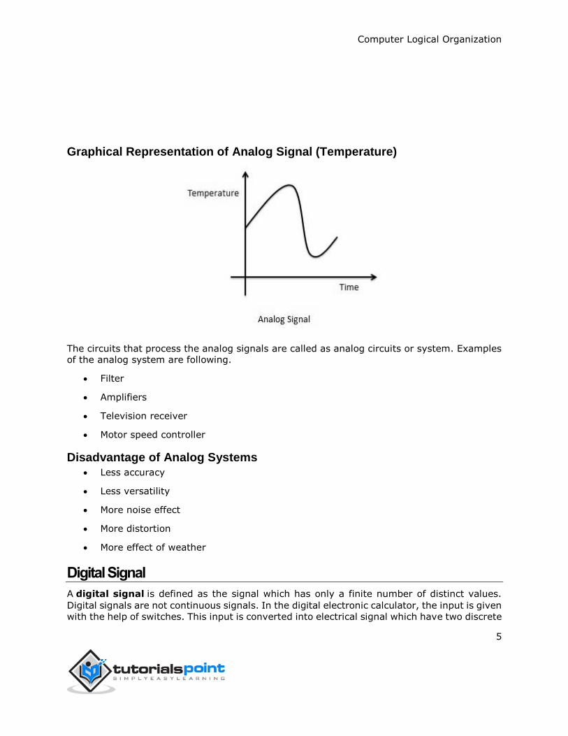
Graphical Representation of Analog Signal (Temperature)
The circuits that process the analog signals are called as analog circuits or system. Examples of the analog system are following.
Filter
Amplifiers
Television receiver
Motor speed controller
Disadvantage of Analog Systems
Less accuracy
Less versatility
More noise effect
More distortion
More effect of weather
Digital Signal
A digital signal is defined as the signal which has only a finite number of distinct values.
Digital signals are not continuous signals. In the digital electronic calculator, the input is given
with the help of switches. This input is converted into electrical signal which have two discrete
Computer Logical Organization
6
values or levels. One of these may be called low level and another is called high level. The
signal will always be one of the two levels. This type of signal is called digital signal. Examples
of the digital signal are following.
Binary Signal
Octal Signal
Hexadecimal Signal
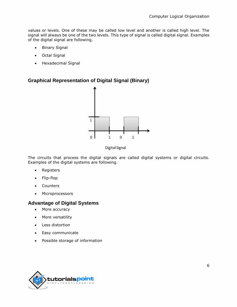
Graphical Representation of Digital Signal (Binary)
The circuits that process the digital signals are called digital systems or digital circuits. Examples of the digital systems are following.
Registers
Flip-flop
Counters
Microprocessors
Advantage of Digital Systems
More accuracy
More versatility
Less distortion
Easy communicate
Possible storage of information
Computer Logical Organization
7
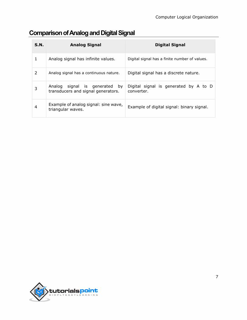
Comparison of Analog and Digital Signal
S.N. Analog Signal Digital Signal
1 Analog signal has infinite values. Digital signal has a finite number of values.
2 Analog signal has a continuous nature. Digital signal has a discrete nature.
3 Analog signal is generated by
transducers and signal generators.
Digital signal is generated by A to D
converter.
4 Example of analog signal: sine wave, triangular waves.
Example of digital signal: binary signal.
Computer Logical Organization
8
A digital system can understand positional number system only where there are a few symbols
called digits and these symbols represent different values depending on the position they
occupy in the number.
A value of each digit in a number can be determined using
The digit
The position of the digit in the number
The base of the number system (where base is defined as the total number of digits
available in the number system).
Decimal Number System
The number system that we use in our day-to-day life is the decimal number system. Decimal
number system has base 10 as it uses 10 digits from 0 to 9. In decimal number system, the
successive positions to the left of the decimal point represents units, tens, hundreds,
thousands and so on.
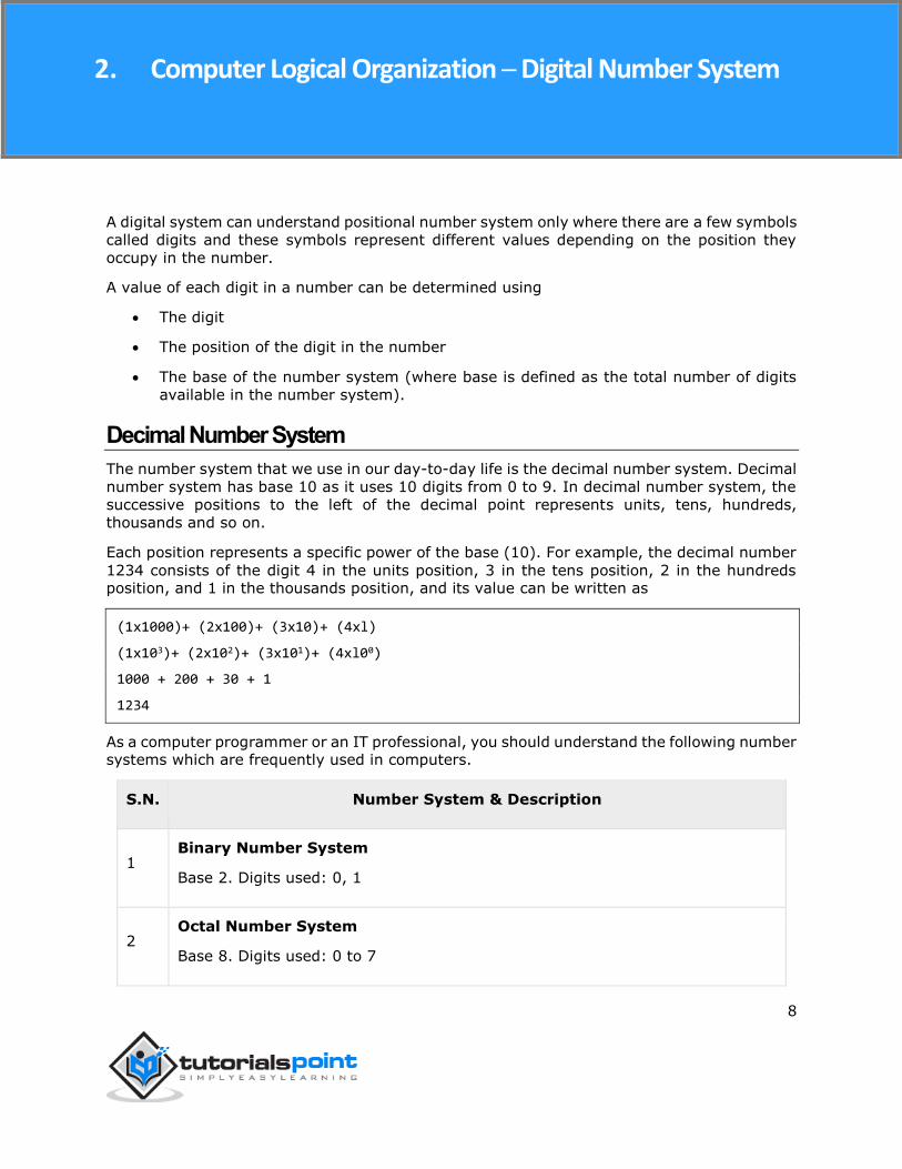
Each position represents a specific power of the base (10). For example, the decimal number
1234 consists of the digit 4 in the units position, 3 in the tens position, 2 in the hundreds position, and 1 in the thousands position, and its value can be written as
(1x1000)+ (2x100)+ (3x10)+ (4xl)
(1x10³)+ (2x10²)+ (3x101)+ (4xl00)
1000 + 200 + 30 + 1
1234
As a computer programmer or an IT professional, you should understand the following number systems which are frequently used in computers.
S.N. Number System & Description
1 Binary Number System
Base 2. Digits used: 0, 1
2 Octal Number System
Base 8. Digits used: 0 to 7
2. Computer Logical Organization ─ Digital Number System
Computer Logical Organization
9
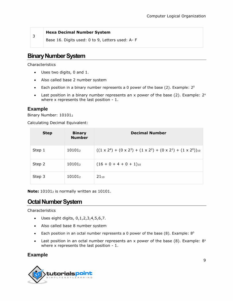
3 Hexa Decimal Number System
Base 16. Digits used: 0 to 9, Letters used: A- F
Binary Number System
Characteristics
Uses two digits, 0 and 1.
Also called base 2 number system
Each position in a binary number represents a 0 power of the base (2). Example: 20
Last position in a binary number represents an x power of the base (2). Example: 2x
where x represents the last position - 1.
Example
Binary Number: 101012
Calculating Decimal Equivalent:
Step Binary
Number
Decimal Number
Step 1 101012 ((1 x 24) + (0 x 23) + (1 x 22) + (0 x 21) + (1 x 20))10
Step 2 101012 (16 + 0 + 4 + 0 + 1)10
Step 3 101012 2110
Note: 101012 is normally written as 10101.
Octal Number System
Characteristics
Uses eight digits, 0,1,2,3,4,5,6,7.
Also called base 8 number system
Each position in an octal number represents a 0 power of the base (8). Example: 80
Last position in an octal number represents an x power of the base (8). Example: 8x
where x represents the last position - 1.
Example
Computer Logical Organization
10
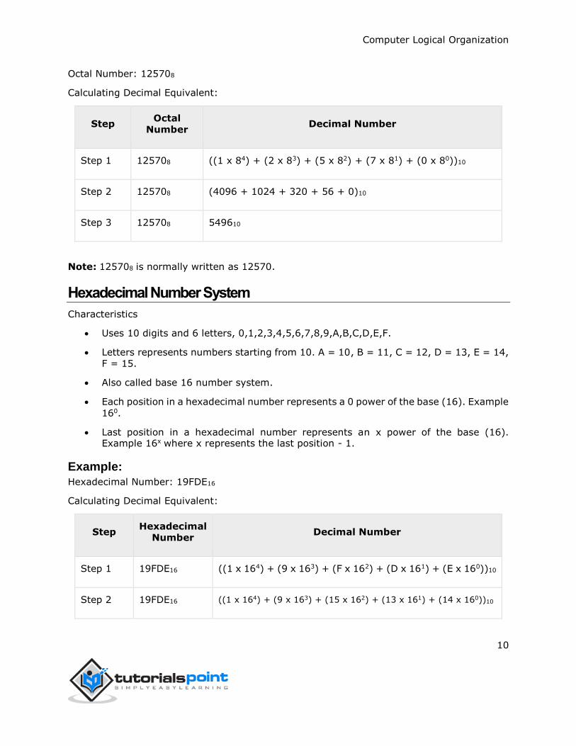
Octal Number: 125708
Calculating Decimal Equivalent:
Step Octal
Number Decimal Number
Step 1 125708 ((1 x 84) + (2 x 83) + (5 x 82) + (7 x 81) + (0 x 80))10
Step 2 125708 (4096 + 1024 + 320 + 56 + 0)10
Step 3 125708 549610
Note: 125708 is normally written as 12570.
Hexadecimal Number System
Characteristics
Uses 10 digits and 6 letters, 0,1,2,3,4,5,6,7,8,9,A,B,C,D,E,F.
Letters represents numbers starting from 10. A = 10, B = 11, C = 12, D = 13, E = 14, F = 15.
Also called base 16 number system.
Each position in a hexadecimal number represents a 0 power of the base (16). Example
160.
Last position in a hexadecimal number represents an x power of the base (16). Example 16x where x represents the last position - 1.
Example:
Hexadecimal Number: 19FDE16
Calculating Decimal Equivalent:
Step Hexadecimal
Number Decimal Number
Step 1 19FDE16 ((1 x 164) + (9 x 163) + (F x 162) + (D x 161) + (E x 160))10
Step 2 19FDE16 ((1 x 164) + (9 x 163) + (15 x 162) + (13 x 161) + (14 x 160))10

Computer Logical Organization
11
Step 3 19FDE16 (65536+ 36864 + 3840 + 208 + 14)10
Step 4 19FDE16 10646210
Note: 19FDE16 is normally written as 19FDE.
Computer Logical Organization
12
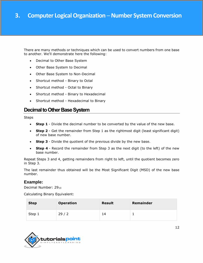
There are many methods or techniques which can be used to convert numbers from one base to another. We'll demonstrate here the following:
Decimal to Other Base System
Other Base System to Decimal
Other Base System to Non-Decimal
Shortcut method - Binary to Octal
Shortcut method - Octal to Binary
Shortcut method - Binary to Hexadecimal
Shortcut method - Hexadecimal to Binary
Decimal to Other Base System
Steps
Step 1 - Divide the decimal number to be converted by the value of the new base.
Step 2 - Get the remainder from Step 1 as the rightmost digit (least significant digit)
of new base number.
Step 3 - Divide the quotient of the previous divide by the new base.
Step 4 - Record the remainder from Step 3 as the next digit (to the left) of the new
base number.
Repeat Steps 3 and 4, getting remainders from right to left, until the quotient becomes zero
in Step 3.
The last remainder thus obtained will be the Most Significant Digit (MSD) of the new base number.
Example:
Decimal Number: 2910
Calculating Binary Equivalent:
Step Operation Result Remainder
Step 1 29 / 2 14 1
3. Computer Logical Organization ─ Number System Conversion
Computer Logical Organization
13
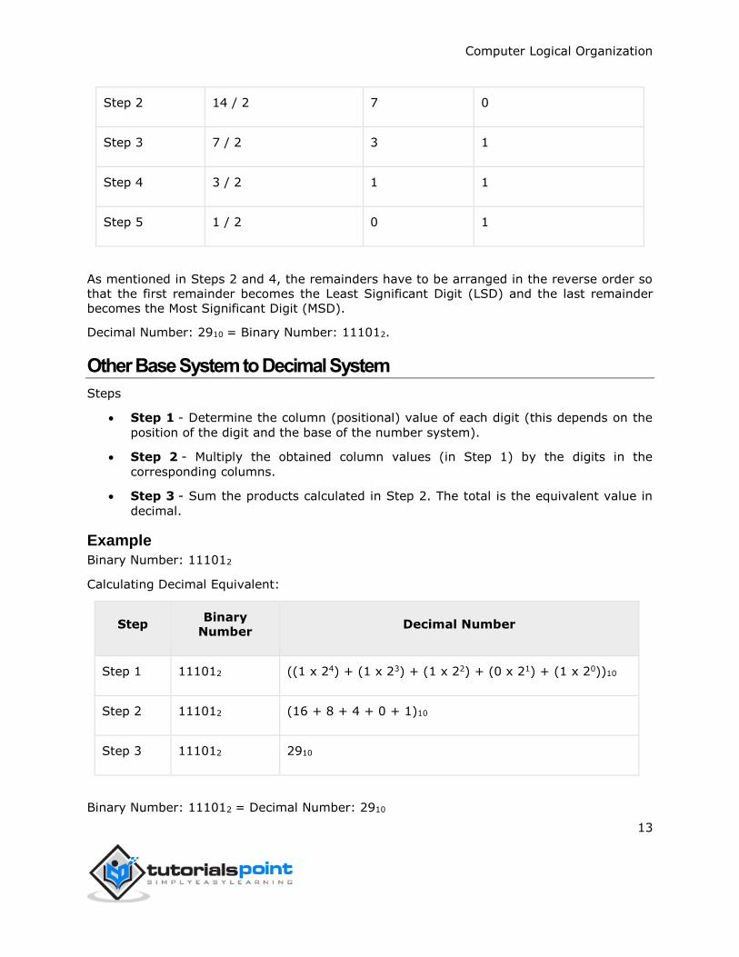
Step 2 14 / 2 7 0
Step 3 7 / 2 3 1
Step 4 3 / 2 1 1
Step 5 1 / 2 0 1
As mentioned in Steps 2 and 4, the remainders have to be arranged in the reverse order so
that the first remainder becomes the Least Significant Digit (LSD) and the last remainder
becomes the Most Significant Digit (MSD).
Decimal Number: 2910 = Binary Number: 111012.
Other Base System to Decimal System
Steps
Step 1 - Determine the column (positional) value of each digit (this depends on the
position of the digit and the base of the number system).
Step 2 - Multiply the obtained column values (in Step 1) by the digits in the
corresponding columns.
Step 3 - Sum the products calculated in Step 2. The total is the equivalent value in
decimal.
Example
Binary Number: 111012
Calculating Decimal Equivalent:
Step Binary
Number Decimal Number
Step 1 111012 ((1 x 24) + (1 x 23) + (1 x 22) + (0 x 21) + (1 x 20))10
Step 2 111012 (16 + 8 + 4 + 0 + 1)10
Step 3 111012 2910
Binary Number: 111012 = Decimal Number: 2910
Computer Logical Organization
14
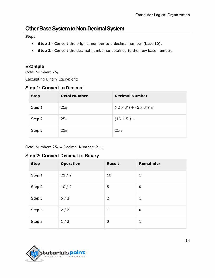
Other Base System to Non-Decimal System
Steps
Step 1 - Convert the original number to a decimal number (base 10).
Step 2 - Convert the decimal number so obtained to the new base number.
Example
Octal Number: 258
Calculating Binary Equivalent:
Step 1: Convert to Decimal
Step Octal Number Decimal Number
Step 1 258 ((2 x 81) + (5 x 80))10
Step 2 258 (16 + 5 )10
Step 3 258 2110
Octal Number: 258 = Decimal Number: 2110
Step 2: Convert Decimal to Binary
Step Operation Result Remainder
Step 1 21 / 2 10 1
Step 2 10 / 2 5 0
Step 3 5 / 2 2 1
Step 4 2 / 2 1 0
Step 5 1 / 2 0 1
Computer Logical Organization
15
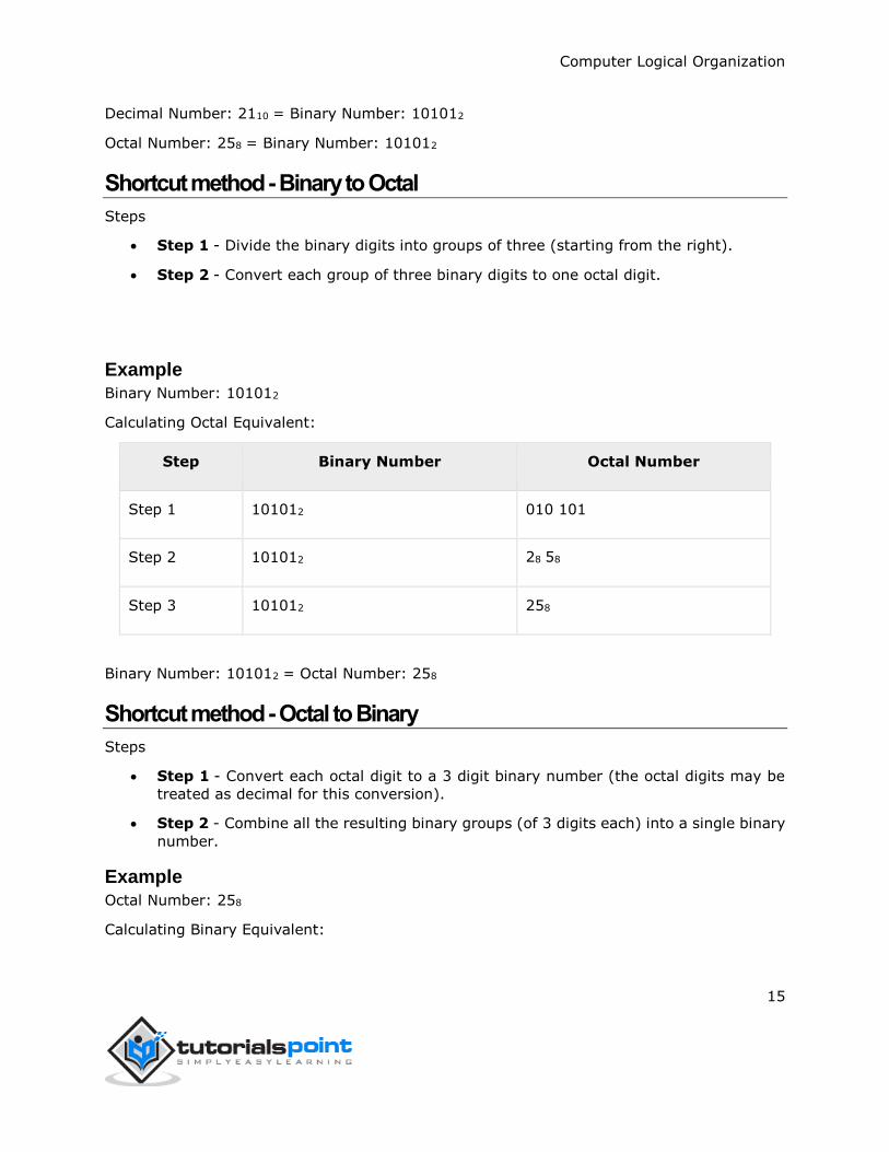
Decimal Number: 2110 = Binary Number: 101012
Octal Number: 258 = Binary Number: 101012
Shortcut method - Binary to Octal
Steps
Step 1 - Divide the binary digits into groups of three (starting from the right).
Step 2 - Convert each group of three binary digits to one octal digit.
Example
Binary Number: 101012
Calculating Octal Equivalent:
Step Binary Number Octal Number
Step 1 101012 010 101
Step 2 101012 28 58
Step 3 101012 258
Binary Number: 101012 = Octal Number: 258
Shortcut method - Octal to Binary
Steps
Step 1 - Convert each octal digit to a 3 digit binary number (the octal digits may be
treated as decimal for this conversion).
Step 2 - Combine all the resulting binary groups (of 3 digits each) into a single binary
number.
Example
Octal Number: 258
Calculating Binary Equivalent:
Computer Logical Organization
16
Step Octal Number Binary Number
Step 1 258 210 510
Step 2 258 0102 1012
Step 3 258 0101012
Octal Number: 258 = Binary Number: 101012
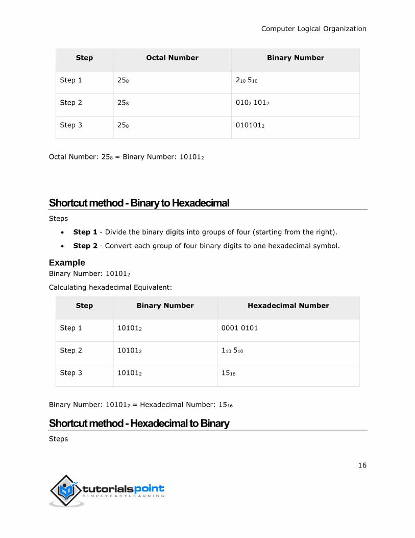
Shortcut method - Binary to Hexadecimal
Steps
Step 1 - Divide the binary digits into groups of four (starting from the right).
Step 2 - Convert each group of four binary digits to one hexadecimal symbol.
Example
Binary Number: 101012
Calculating hexadecimal Equivalent:
Step Binary Number Hexadecimal Number
Step 1 101012 0001 0101
Step 2 101012 110 510
Step 3 101012 1516
Binary Number: 101012 = Hexadecimal Number: 1516
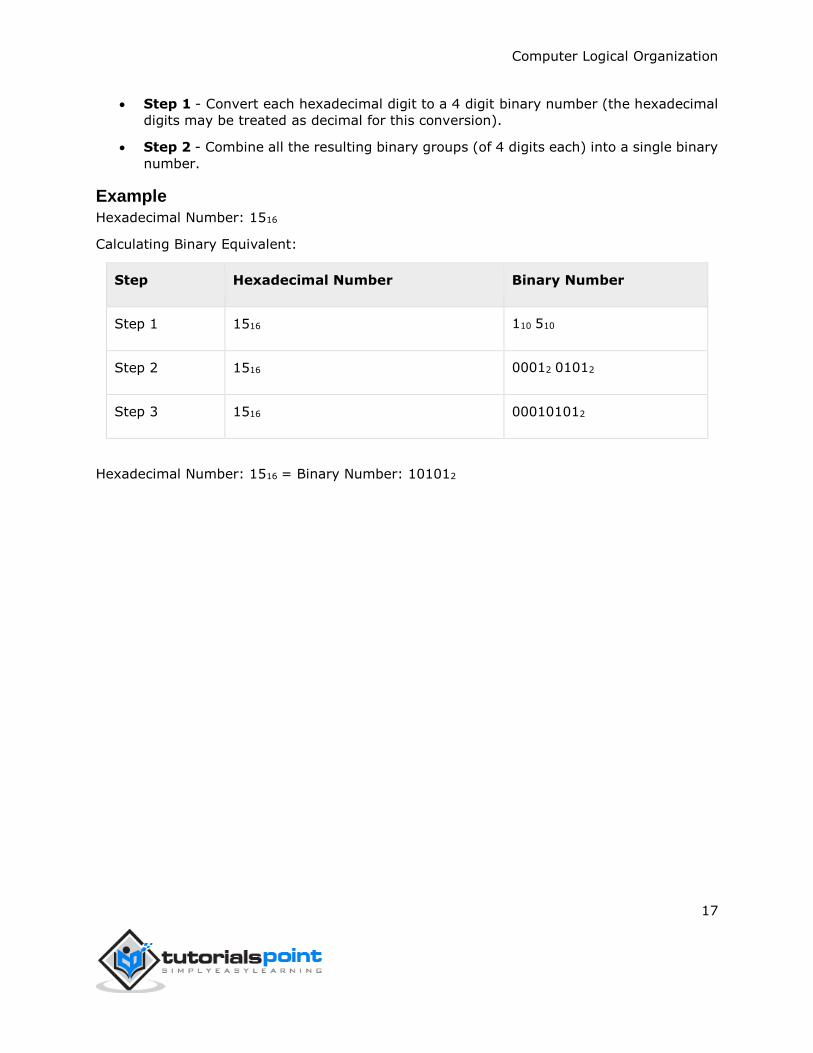
Shortcut method - Hexadecimal to Binary
Steps
Computer Logical Organization
17
Step 1 - Convert each hexadecimal digit to a 4 digit binary number (the hexadecimal
digits may be treated as decimal for this conversion).
Step 2 - Combine all the resulting binary groups (of 4 digits each) into a single binary
number.
Example
Hexadecimal Number: 1516
Calculating Binary Equivalent:
Step Hexadecimal Number Binary Number
Step 1 1516 110 510
Step 2 1516 00012 01012
Step 3 1516 000101012
Hexadecimal Number: 1516 = Binary Number: 101012
Computer Logical Organization
18
In the coding, when numbers, letters or words are represented by a specific group of symbols,
it is said that the number, letter or word is being encoded. The group of symbols is called as
a code. The digital data is represented, stored and transmitted as group of binary bits. This group is also called as binary code. The binary code is represented by the number as well as
alphanumeric letter.
Advantages of Binary Code
Following is the list of advantages that binary code offers.
Binary codes are suitable for the computer applications.
Binary codes are suitable for the digital communications.
Binary codes make the analysis and designing of digital circuits if we use the binary codes.
Since only 0 & 1 are being used, implementation becomes easy.
Classification of binary codes
The codes are broadly categorized into following four categories.
Weighted Codes
Non-Weighted Codes
Binary Coded Decimal Code
Alphanumeric Codes
Error Detecting Codes
Error Correcting Codes
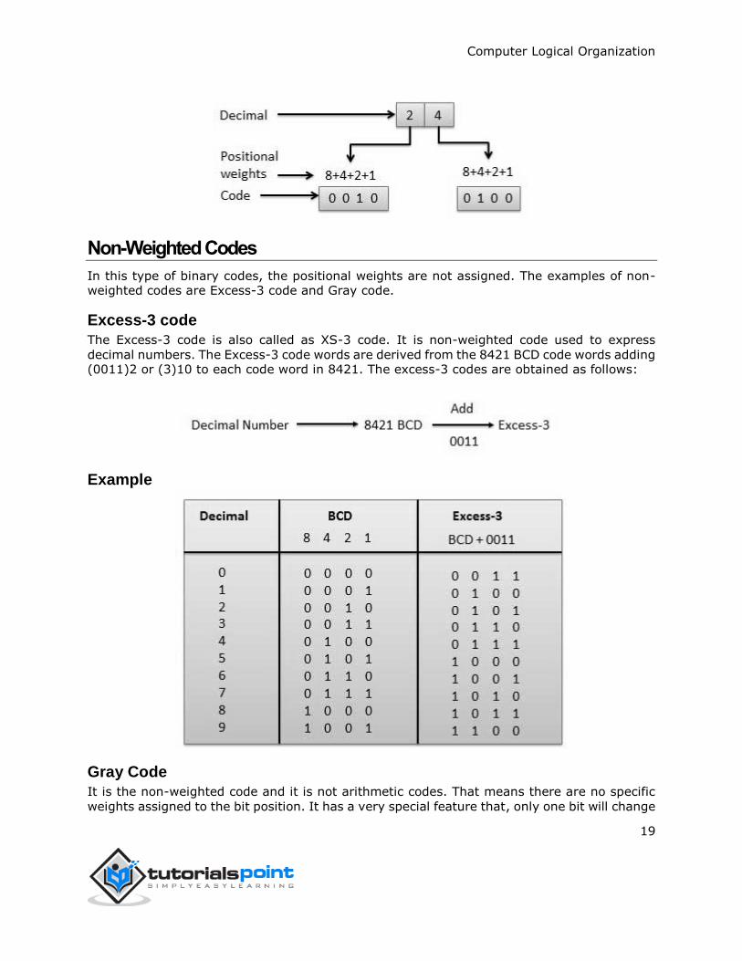
Weighted Codes
Weighted binary codes are those binary codes which obey the positional weight principle.
Each position of the number represents a specific weight. Several systems of the codes are
used to express the decimal digits 0 through 9. In these codes each decimal digit is represented by a group of four bits.
4. Computer Logical Organization ─ Binary Codes
Computer Logical Organization
19
Non-Weighted Codes
In this type of binary codes, the positional weights are not assigned. The examples of non-weighted codes are Excess-3 code and Gray code.
Excess-3 code
The Excess-3 code is also called as XS-3 code. It is non-weighted code used to express
decimal numbers. The Excess-3 code words are derived from the 8421 BCD code words adding (0011)2 or (3)10 to each code word in 8421. The excess-3 codes are obtained as follows:
Example
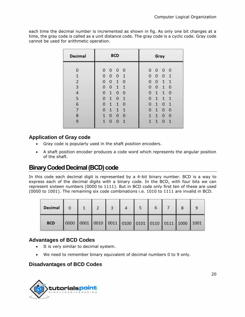
Gray Code
It is the non-weighted code and it is not arithmetic codes. That means there are no specific
weights assigned to the bit position. It has a very special feature that, only one bit will change
Computer Logical Organization
20
each time the decimal number is incremented as shown in fig. As only one bit changes at a
time, the gray code is called as a unit distance code. The gray code is a cyclic code. Gray code
cannot be used for arithmetic operation.
Application of Gray code
Gray code is popularly used in the shaft position encoders.
A shaft position encoder produces a code word which represents the angular position of the shaft.
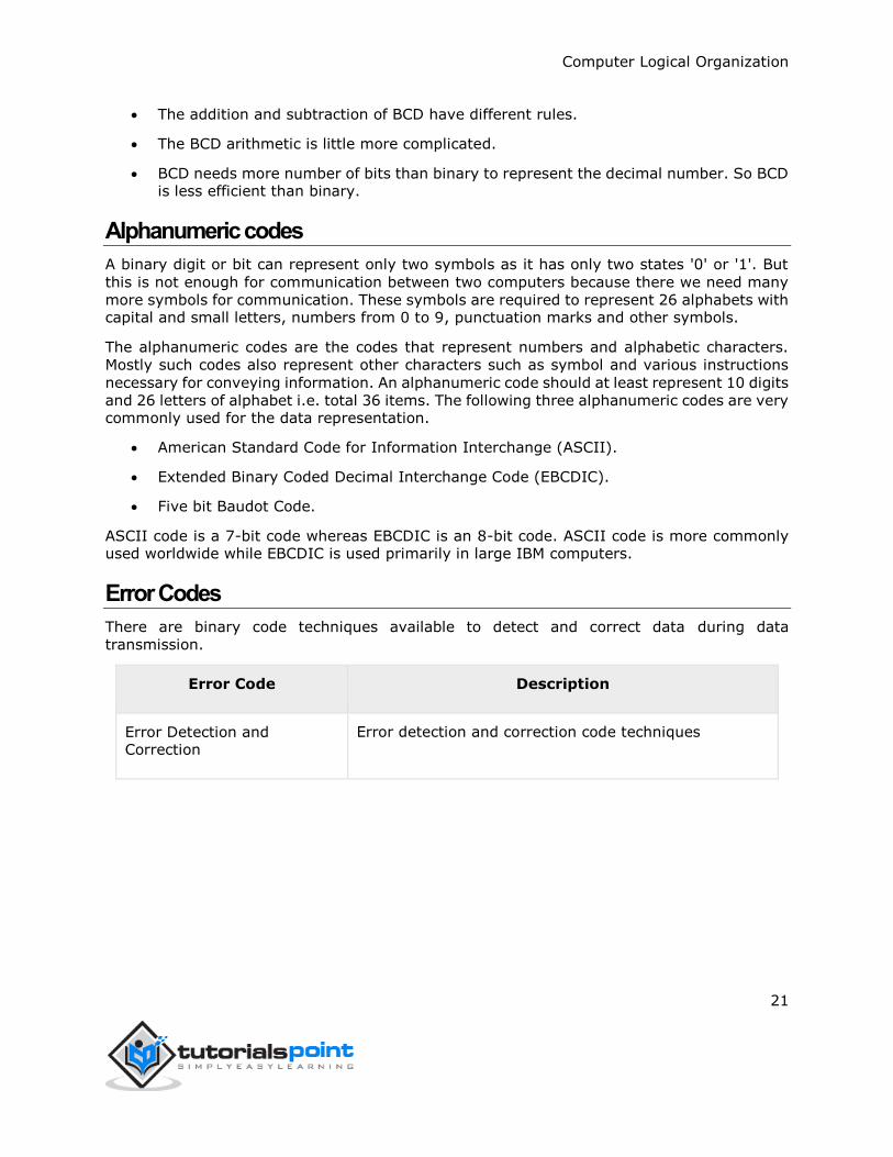
Binary Coded Decimal (BCD) code
In this code each decimal digit is represented by a 4-bit binary number. BCD is a way to
express each of the decimal digits with a binary code. In the BCD, with four bits we can
represent sixteen numbers (0000 to 1111). But in BCD code only first ten of these are used (0000 to 1001). The remaining six code combinations i.e. 1010 to 1111 are invalid in BCD.
Advantages of BCD Codes
It is very similar to decimal system.
We need to remember binary equivalent of decimal numbers 0 to 9 only.
Disadvantages of BCD Codes
Computer Logical Organization
21
The addition and subtraction of BCD have different rules.
The BCD arithmetic is little more complicated.
BCD needs more number of bits than binary to represent the decimal number. So BCD is less efficient than binary.
Alphanumeric codes
A binary digit or bit can represent only two symbols as it has only two states '0' or '1'. But
this is not enough for communication between two computers because there we need many
more symbols for communication. These symbols are required to represent 26 alphabets with capital and small letters, numbers from 0 to 9, punctuation marks and other symbols.
The alphanumeric codes are the codes that represent numbers and alphabetic characters.
Mostly such codes also represent other characters such as symbol and various instructions
necessary for conveying information. An alphanumeric code should at least represent 10 digits
and 26 letters of alphabet i.e. total 36 items. The following three alphanumeric codes are very commonly used for the data representation.
American Standard Code for Information Interchange (ASCII).
Extended Binary Coded Decimal Interchange Code (EBCDIC).
Five bit Baudot Code.
ASCII code is a 7-bit code whereas EBCDIC is an 8-bit code. ASCII code is more commonly used worldwide while EBCDIC is used primarily in large IBM computers.
Error Codes
There are binary code techniques available to detect and correct data during data
transmission.
Error Code Description
Error Detection and Correction
Error detection and correction code techniques
Computer Logical Organization
22
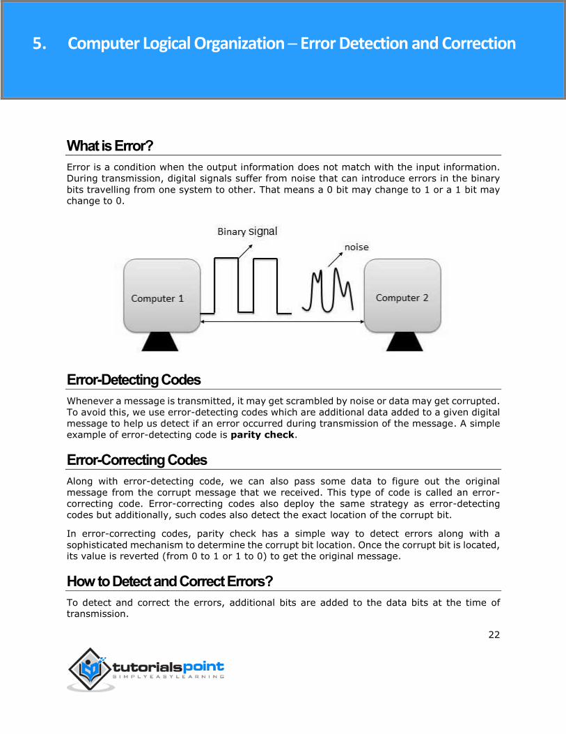
What is Error?
Error is a condition when the output information does not match with the input information.
During transmission, digital signals suffer from noise that can introduce errors in the binary
bits travelling from one system to other. That means a 0 bit may change to 1 or a 1 bit may change to 0.
Error-Detecting Codes
Whenever a message is transmitted, it may get scrambled by noise or data may get corrupted.
To avoid this, we use error-detecting codes which are additional data added to a given digital
message to help us detect if an error occurred during transmission of the message. A simple
example of error-detecting code is parity check.
Error-Correcting Codes
Along with error-detecting code, we can also pass some data to figure out the original
message from the corrupt message that we received. This type of code is called an error-
correcting code. Error-correcting codes also deploy the same strategy as error-detecting
codes but additionally, such codes also detect the exact location of the corrupt bit.
In error-correcting codes, parity check has a simple way to detect errors along with a
sophisticated mechanism to determine the corrupt bit location. Once the corrupt bit is located, its value is reverted (from 0 to 1 or 1 to 0) to get the original message.
How to Detect and Correct Errors?
To detect and correct the errors, additional bits are added to the data bits at the time of transmission.
5. Computer Logical Organization ─ Error Detection and Correction
Computer Logical Organization
23
The additional bits are called parity bits. They allow detection or correction of the errors.
The data bits along with the parity bits form a code word.
Parity Checking of Error Detection
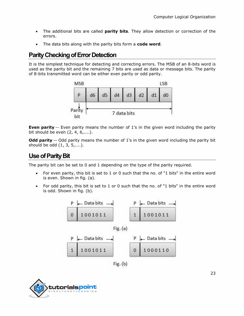
It is the simplest technique for detecting and correcting errors. The MSB of an 8-bits word is
used as the parity bit and the remaining 7 bits are used as data or message bits. The parity of 8-bits transmitted word can be either even parity or odd parity.
Even parity -- Even parity means the number of 1's in the given word including the parity
bit should be even (2, 4, 6,....).
Odd parity -- Odd parity means the number of 1's in the given word including the parity bit should be odd (1, 3, 5,....).
Use of Parity Bit
The parity bit can be set to 0 and 1 depending on the type of the parity required.
For even parity, this bit is set to 1 or 0 such that the no. of "1 bits" in the entire word is even. Shown in fig. (a).
For odd parity, this bit is set to 1 or 0 such that the no. of "1 bits" in the entire word
is odd. Shown in fig. (b).
Computer Logical Organization
24
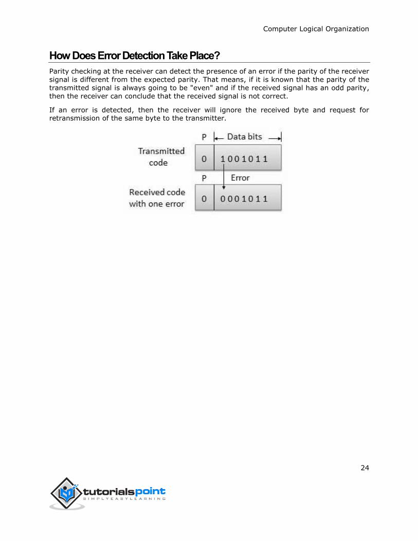
How Does Error Detection Take Place?
Parity checking at the receiver can detect the presence of an error if the parity of the receiver
signal is different from the expected parity. That means, if it is known that the parity of the
transmitted signal is always going to be "even" and if the received signal has an odd parity,
then the receiver can conclude that the received signal is not correct.
If an error is detected, then the receiver will ignore the received byte and request for retransmission of the same byte to the transmitter.
Computer Logical Organization
25
There are many methods or techniques which can be used to convert code from one format to another. We'll demonstrate here the following
Binary to BCD Conversion
BCD to Binary Conversion
BCD to Excess-3
Excess-3 to BCD
Binary to BCD Conversion
Steps
Step 1 -- Convert the binary number to decimal.
Step 2 -- Convert decimal number to BCD.
Example: convert (11101)2 to BCD.
Step 1 - Convert to Decimal
Binary Number: 111012
Calculating Decimal Equivalent:
Step Binary Number
Decimal Number
Step 1 111012 ((1 x 24) + (1 x 23) + (1 x 22) + (0 x 21) + (1 x 20))10
Step 2 111012 (16 + 8 + 4 + 0 + 1)10
Step 3 111012 2910
Binary Number: 111012 = Decimal Number: 2910
Step 2 - Convert to BCD
Decimal Number: 2910
Calculating BCD Equivalent. Convert each digit into groups of four binary digits equivalent.
6. Computer Logical Organization ─ Codes Conversion
Computer Logical Organization
26
Step Decimal Number Conversion
Step 1 2910 00102 10012
Step 2 2910 00101001BCD
Result
(11101)2 = (00101001)BCD
BCD to Binary Conversion
Steps
Step 1 -- Convert the BCD number to decimal.
Step 2 -- Convert decimal to binary.
Example: convert (00101001)BCD to Binary.
Step 1 - Convert to BCD
BCD Number: (00101001)BCD
Calculating Decimal Equivalent. Convert each four digit into a group and get decimal equivalent for each group.
Step BCD Number Conversion
Step 1 (00101001)BCD 00102 10012
Step 2 (00101001)BCD 210 910
Step 3 (00101001)BCD 2910
BCD Number: (00101001)BCD = Decimal Number: 2910
Step 2 - Convert to Binary
Used long division method for decimal to binary conversion.
Decimal Number: 2910
Calculating Binary Equivalent:
Computer Logical Organization
27
Step Operation Result Remainder
Step 1 29 / 2 14 1
Step 2 14 / 2 7 0
Step 3 7 / 2 3 1
Step 4 3 / 2 1 1
Step 5 1 / 2 0 1
As mentioned in Steps 2 and 4, the remainders have to be arranged in the reverse order so
that the first remainder becomes the least significant digit (LSD) and the last remainder becomes the most significant digit (MSD).
Decimal Number: 2910 = Binary Number: 111012
Result
(00101001)BCD = (11101)2
BCD to Excess-3
Steps
Step 1 -- Convert BCD to decimal.
Step 2 -- Add (3)10 to this decimal number.
Step 3 -- Convert into binary to get excess-3 code.
Example: convert (1001)BCD to Excess-3.
Step 1 - Convert to decimal (1001)BCD = 910
Step 2 - Add 3 to decimal (9)10 + (3)10 = (12)10
Step 3 - Convert to Excess-3 (12)10 = (1100)2
Result
Computer Logical Organization
28
(1001)BCD = (1100)XS-3
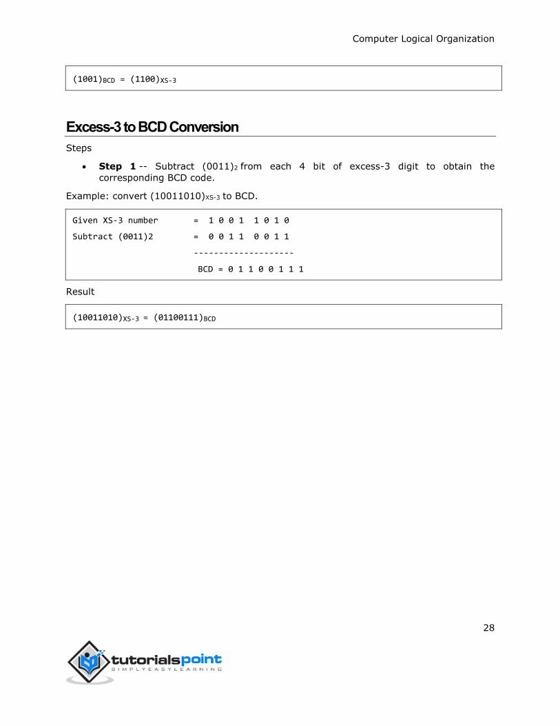
Excess-3 to BCD Conversion
Steps
Step 1 -- Subtract (0011)2 from each 4 bit of excess-3 digit to obtain the
corresponding BCD code.
Example: convert (10011010)XS-3 to BCD.
Given XS-3 number = 1 0 0 1 1 0 1 0
Subtract (0011)2 = 0 0 1 1 0 0 1 1
--------------------
BCD = 0 1 1 0 0 1 1 1
Result
(10011010)XS-3 = (01100111)BCD
Computer Logical Organization
29
Complements are used in the digital computers in order to simplify the subtraction operation
and for the logical manipulations. For each radix-r system (radix r represents base of number
system) there are two types of complements.
S.N. Complement Description
1 Radix Complement The radix complement is referred to as the r's complement
2 Diminished Radix Complement
The diminished radix complement is referred to as the (r-1)'s complement
Binary System Complements
As the binary system has base r = 2. So the two types of complements for the binary system
are 2's complement and 1's complement.
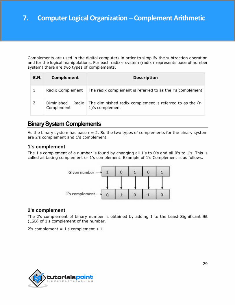
1's complement
The 1's complement of a number is found by changing all 1's to 0's and all 0's to 1's. This is called as taking complement or 1's complement. Example of 1's Complement is as follows.
2's complement
The 2's complement of binary number is obtained by adding 1 to the Least Significant Bit (LSB) of 1's complement of the number.
2's complement = 1's complement + 1
7. Computer Logical Organization ─ Complement Arithmetic

Computer Logical Organization
30
End of ebook preview
If you liked what you saw… Buy it from our store @ https://store.tutorialspoint.com


![Database Modeling & Design - Online Tutorials ( Books …dbmanagement.info/Books/MIX/[2006]_database_modeling_and...Database Modeling & Design: Logical Design Fourth Edition TOBY TEOREY](https://img.pdfslide.us/doc/110x75/5af6d19f7f8b9a74448ffb1c/database-modeling-design-online-tutorials-books-2006databasemodelinganddatabase.jpg)