Embed Size (px)
Citation preview
Computer Graphics
Si Lu
Fall 2017
http://www.cs.pdx.edu/~lusi/CS447/CS447_547_Comput
er_Graphics.htm
10/18/2017
Last time
More 2D Transformations
Homogeneous Coordinates
3D Transformations
The Viewing Pipeline
2
Today
Perspective projection
Homework 2 due in class today
In-class Middle-Term
Wednesday, Nov. 1
Close-book exam
Notes on 1 page of A4 or Letter size paper
To-know list available online
3
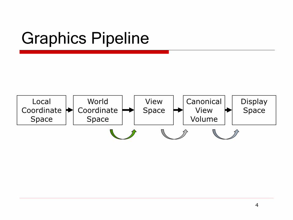
Graphics Pipeline
4
Local Coordinate
Space
World Coordinate
Space
View Space
Canonical View
Volume
Display Space
Defining Cameras
View Space is the camera’s local coordinates
The camera is in some location
The camera is looking in some direction
It is tilted in some orientation
It is inconvenient to model everything in terms of View
Space
Biggest problem is that the camera might be moving – we don’t want to have to explicitly move every object too
We specify the camera, and hence View Space, with
respect to World Space
How can we specify the camera?
5

Specifying a View
The location of View Space with respect to World Space
A point in World Space for the origin of View Space, (ex,ey,ez)
The direction in which we are looking: gaze direction
Specified as a vector: (gx,gy,gz)
This vector will be normal to the image plane
A direction that we want to appear up in the image
(upx,upy,upz), this vector does not have to be perpendicular to g
We also need the size of the view volume – l,r,t,b,n,f Specified with respect to the eye and image plane, not the world
6
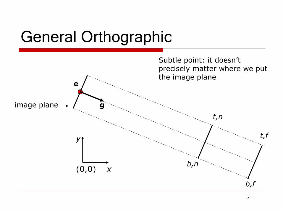
General Orthographic
7
(0,0) x
y
e
image plane g
b,n
b,f
t,n
t,f
Subtle point: it doesn’t precisely matter where we put the image plane
Getting there…
We wish to end up in View Space, so we need a
coordinate system with:
A vector toward the viewer, View Space z
A vector pointing right in the image plane, View Space x
A vector pointing up in the image plane, View Space y
The origin at the eye, View Space (0,0,0)
We must:
Say what each of these vectors are in World Space
Transform points from the World Space into View Space
We can then apply the orthographic projection to get to Canonical View Space, and so on
8
View Space in World Space
Given our camera definition, in World Space:
Where is the origin of view space? It will transform into (0,0,0)view
What is the normal to the view plane, w? It will become zview
How do we find the right vector, u? It will become xview
How do we find the up vector, v? It will become yview
Given these points, how do we do the transformation?
9
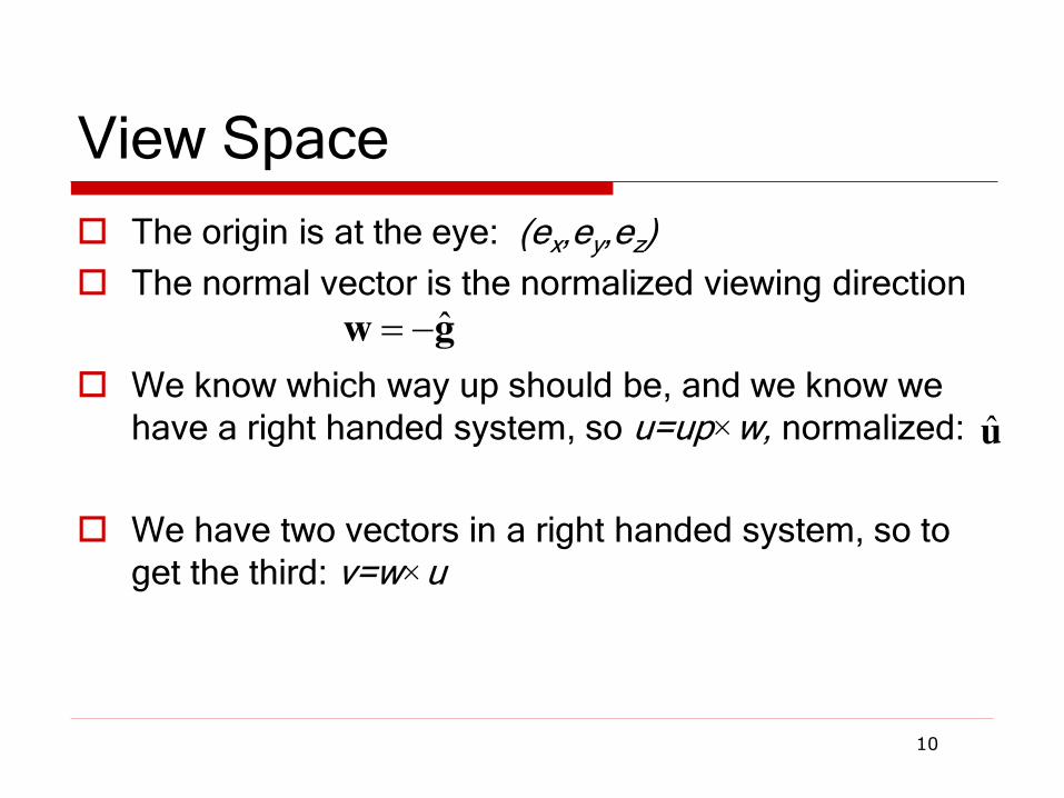
View Space
The origin is at the eye: (ex,ey,ez)
The normal vector is the normalized viewing direction
We know which way up should be, and we know we have a right handed system, so u=up×w, normalized:
We have two vectors in a right handed system, so to get the third: v=w×u
10
gw ˆ
u
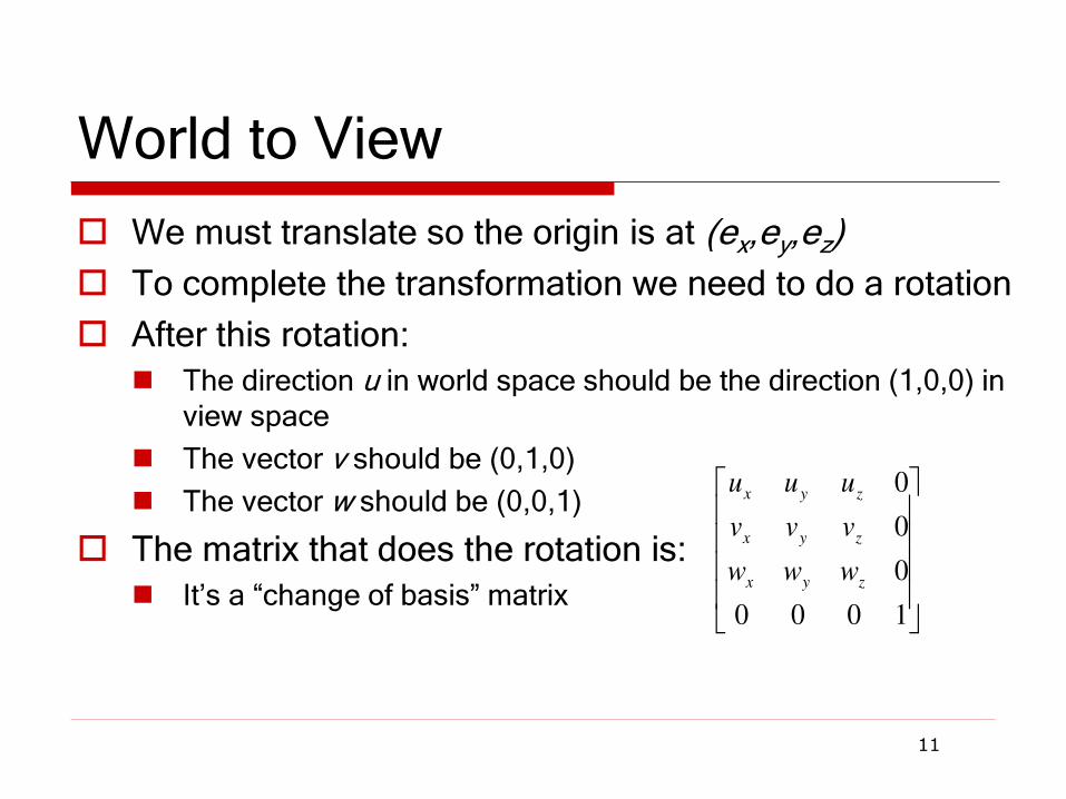
World to View
We must translate so the origin is at (ex,ey,ez)
To complete the transformation we need to do a rotation
After this rotation:
The direction u in world space should be the direction (1,0,0) in view space
The vector v should be (0,1,0)
The vector w should be (0,0,1)
The matrix that does the rotation is:
It’s a “change of basis” matrix
11
1000
0
0
0
zyx
zyx
zyx
www
vvv
uuu

All Together
We apply a translation and then a rotation, so the result is:
And to go all the way from world to screen:
12
1000
w
v
u
1000
100
010
001
1000
0
0
0
e
e
e
Mzyx
zyx
zyx
z
y
x
zyx
zyx
zyx
viewworldwww
vvv
uuu
e
e
e
www
vvv
uuu
worldcanonicalworldcanonical
viewworldcanonicalviewcanonicalworld
xMx
MMM

Graphics Pipeline
13
Local Coordinate
Space
World Coordinate
Space
View Space
Canonical View
Volume
Display Space
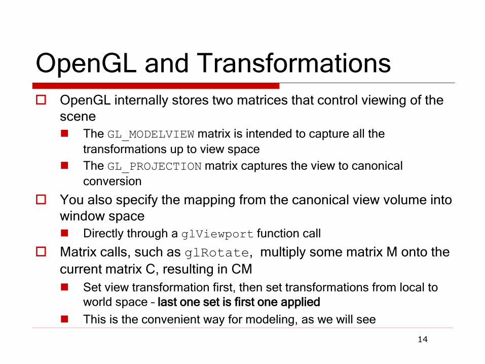
OpenGL and Transformations OpenGL internally stores two matrices that control viewing of the
scene
The GL_MODELVIEW matrix is intended to capture all the
transformations up to view space
The GL_PROJECTION matrix captures the view to canonical
conversion
You also specify the mapping from the canonical view volume into window space
Directly through a glViewport function call
Matrix calls, such as glRotate, multiply some matrix M onto the
current matrix C, resulting in CM
Set view transformation first, then set transformations from local to
world space – last one set is first one applied
This is the convenient way for modeling, as we will see
14
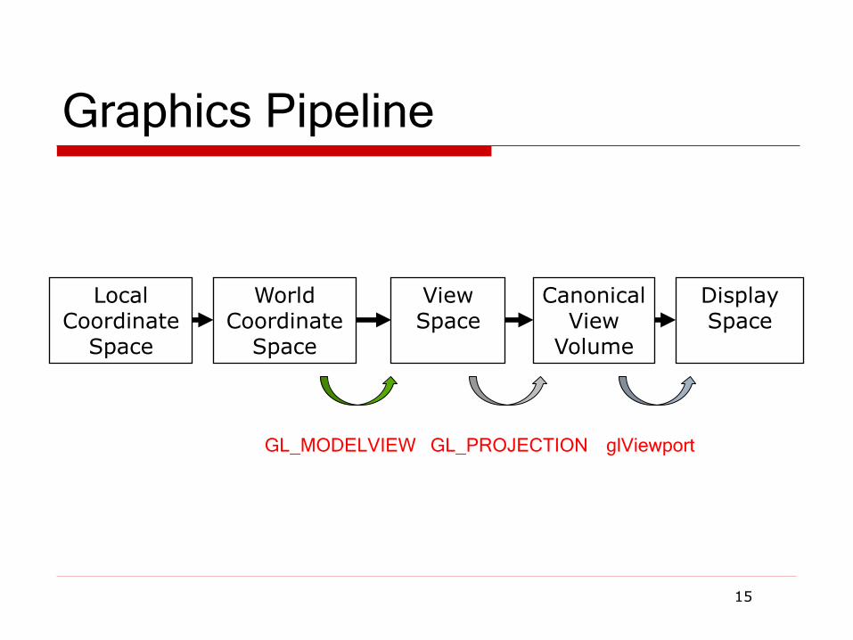
Graphics Pipeline
15
Local Coordinate
Space
World Coordinate
Space
View Space
Canonical View
Volume
Display Space
GL_PROJECTION glViewport GL_MODELVIEW

OpenGL Camera
The default OpenGL image plane has u aligned with the x axis, v aligned with y, and n aligned with z
Means the default camera looks along the negative z axis
Makes it easy to do 2D drawing (no need for any view transformation)
glOrtho(…) sets the view->canonical matrix
Modifies the GL_PROJECTION matrix
gluLookAt(…) sets the world->view matrix
Takes an image center point, a point along the viewing direction and an
up vector
Multiplies a world->view matrix onto the current GL_MODELVIEW matrix
You could do this yourself, using glMultMatrix(…) with the matrix
from the previous slides
16

Typical Usage
17
GLU functions, such as gluLookAt(…), are not part of the
core OpenGL library
They can be implemented with other core OpenGL commands
For example, gluLookAt(…) uses glMultMatrix(…) with the
matrix from the previous slides
They are not dependent on a particular graphics card
glMatrixMode(GL_PROJECTION);
glLoadIdentity();
glOrtho(l, r, b, t, n, f);
glMatrixMode(GL_MODELVIEW);
glLoadIdentity();
gluLookAt(ex,ey,ez,cx,cy,cx,ux,uy,uz);
Left vs Right Handed View Space
You can define u as right, v as up, and n as toward the
viewer: a right handed system uv=w Advantage: Standard mathematical way of doing things
You can also define u as right, v as up and n as into the
scene: a left handed system vu=w Advantage: Bigger n values mean points are further away
OpenGL is right handed
Many older systems, notably the Renderman standard
developed by Pixar, are left handed
18

Graphics Pipeline
19
Local Coordinate
Space
World Coordinate
Space
View Space
Canonical View
Volume
Display Space

Review
View Space is a coordinate system with the viewer
looking down the –z axis, with x to the right and y up
The World->View transformation takes points in world
space and converts them into points in view space
The Projection matrix, or View->Canonical matrix,
takes points in view space and converts them into
points in Canonical View Space
Canonical View Space is a coordinate system with the viewer looking along –z, x to the right, y up, and everything to be drawn inside the cube [-1,1]x[-1,1]x[-1,1] using parallel projection
20

Perspective Projection
21
Abstract camera model - box with a small hole in it
Pinhole cameras work in practice
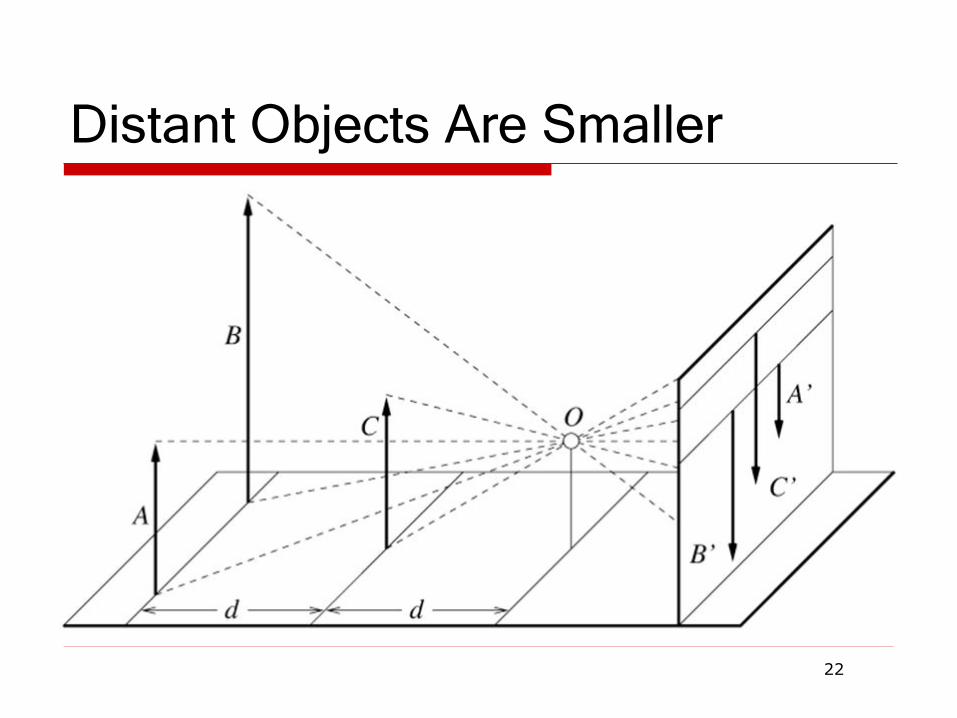
Distant Objects Are Smaller
22
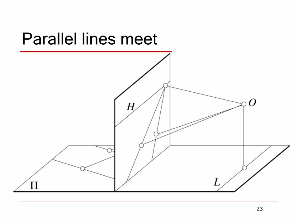
Parallel lines meet
23
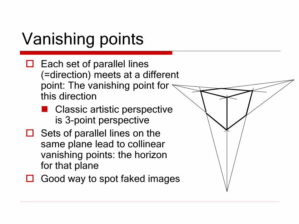
Vanishing points
Each set of parallel lines (=direction) meets at a different point: The vanishing point for this direction
Classic artistic perspective is 3-point perspective
Sets of parallel lines on the same plane lead to collinear vanishing points: the horizon for that plane
Good way to spot faked images
Basic Perspective Projection
We are going to temporarily ignore canonical view
space, and go straight from view to window
Assume you have transformed to view space, with x to
the right, y up, and z back toward the viewer
Assume the origin of view space is at the center of
projection (the eye)
Define a focal distance, d, and put the image plane
there (note d is negative)
You can define d to control the size of the image
25
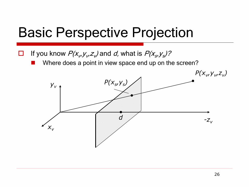
Basic Perspective Projection
If you know P(xv,yv,zv) and d, what is P(xs,ys)?
Where does a point in view space end up on the screen?
26
xv
yv
-zv d
P(xv,yv,zv)
P(xs,ys)

Basic Case
27
Similar triangles gives:
v
vs
z
x
d
x
v
vs
z
y
d
y
yv
-zv
P(xv,yv,zv) P(xs,ys)
View Plane
d

Simple Perspective Transformation
Using homogeneous coordinates we can write:
Our next big advantage to homogeneous coordinates
28
dz
z
y
x
d
y
x
v
v
v
v
s
s
vs
d
PP
0100
0100
0010
0001
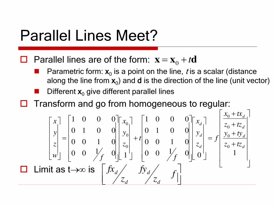
Parallel Lines Meet?
Parallel lines are of the form:
Parametric form: x0 is a point on the line, t is a scalar (distance along the line from x0) and d is the direction of the line (unit vector)
Different x0 give different parallel lines
Transform and go from homogeneous to regular:
Limit as t is
dxx t0
100100
0100
0010
0001
10100
0100
0010
0001
0
0
0
0
0
0
0
d
d
d
d
d
d
d
tzz
tyy
tzz
txx
fz
y
x
f
tz
y
x
fw
z
y
x
f
zfy
zfx
d
d
d
d
General Perspective
The basic equations we have seen give a flavor of
what happens, but they are insufficient for all
applications
They do not get us to a Canonical View Volume
They make assumptions about the viewing conditions
To get to a Canonical Volume, we need a Perspective
Volume …
30
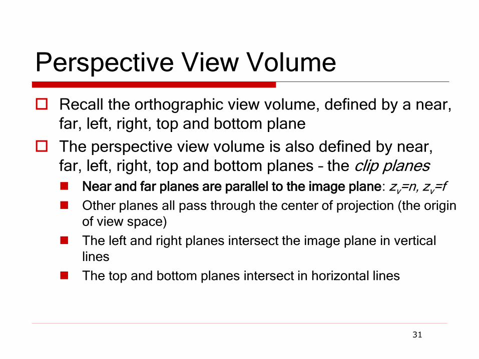
Perspective View Volume
Recall the orthographic view volume, defined by a near,
far, left, right, top and bottom plane
The perspective view volume is also defined by near,
far, left, right, top and bottom planes – the clip planes Near and far planes are parallel to the image plane: zv=n, zv=f
Other planes all pass through the center of projection (the origin of view space)
The left and right planes intersect the image plane in vertical
lines
The top and bottom planes intersect in horizontal lines
31
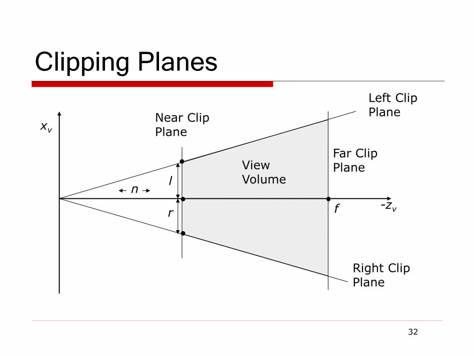
Clipping Planes
32
xv
-zv
Near Clip Plane
Far Clip Plane View
Volume
Left Clip Plane
Right Clip Plane
f
n l
r
Where is the Image Plane?
Notice that it doesn’t really matter where the image plane is located, once you define the view volume
You can move it forward and backward along the z axis and still get the same image, only scaled
The left/right/top/bottom planes are defined according
to where they cut the near clip plane
Or, define the left/right and top/bottom clip planes by
the field of view
33
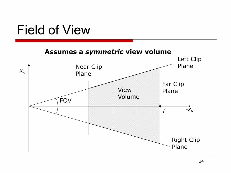
Field of View
34
xv
-zv
Near Clip Plane
Far Clip Plane View
Volume
Left Clip Plane
Right Clip Plane
f
FOV
Assumes a symmetric view volume
Perspective Parameters
We have seen several different ways to describe a
perspective camera
Focal distance, Field of View, Clipping planes
The most general is clipping planes – they directly
describe the region of space you are viewing
For most graphics applications, field of view is the
most convenient
It is image size invariant – having specified the field of view, what you see does not depend on the image size
You can convert one thing to another
35
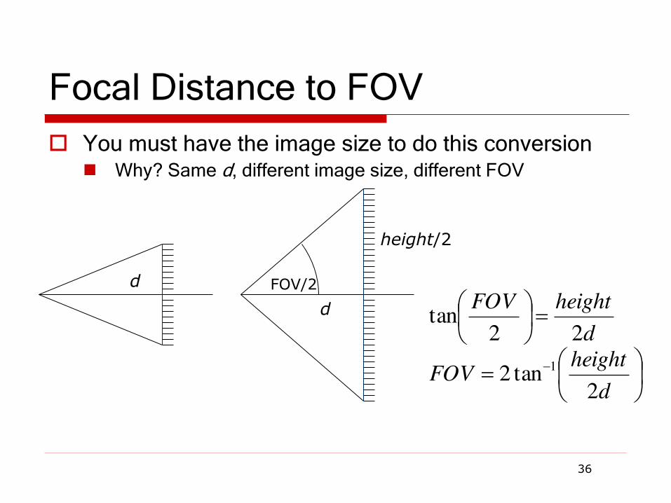
Focal Distance to FOV
You must have the image size to do this conversion Why? Same d, different image size, different FOV
36
d
d
FOV/2
height/2
d
heightFOV
d
heightFOV
2tan2
22tan
1
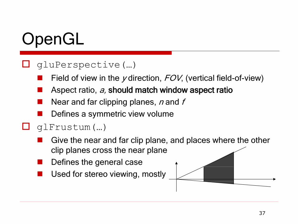
OpenGL
gluPerspective(…) Field of view in the y direction, FOV, (vertical field-of-view)
Aspect ratio, a, should match window aspect ratio
Near and far clipping planes, n and f
Defines a symmetric view volume
glFrustum(…)
Give the near and far clip plane, and places where the other clip planes cross the near plane
Defines the general case
Used for stereo viewing, mostly
37
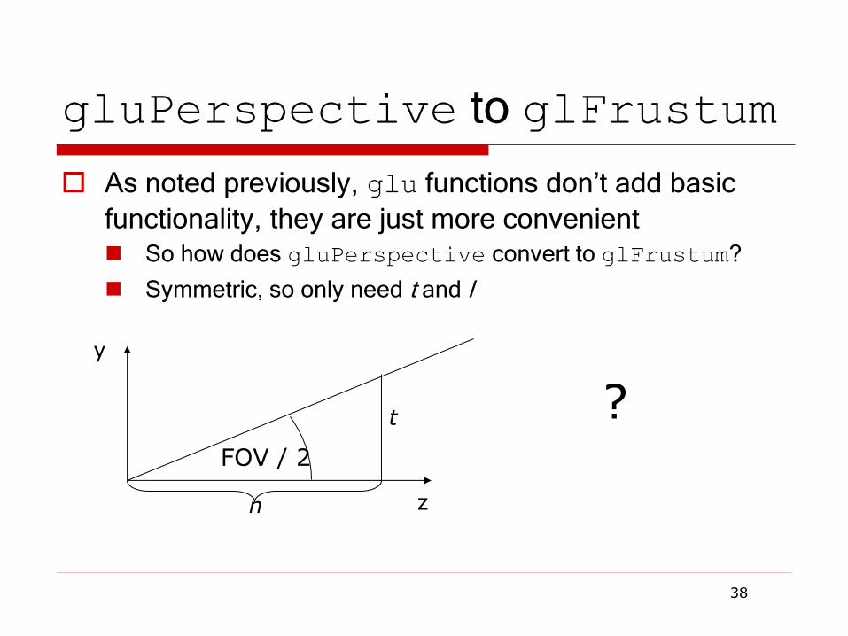
gluPerspective to glFrustum
As noted previously, glu functions don’t add basic functionality, they are just more convenient So how does gluPerspective convert to glFrustum?
Symmetric, so only need t and l
38
y
z
FOV / 2
n
t ?
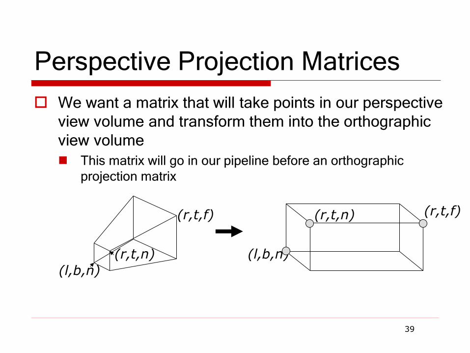
Perspective Projection Matrices
We want a matrix that will take points in our perspective
view volume and transform them into the orthographic
view volume
This matrix will go in our pipeline before an orthographic projection matrix
39
(l,b,n)
(r,t,n) (l,b,n)
(r,t,n) (r,t,f) (r,t,f)
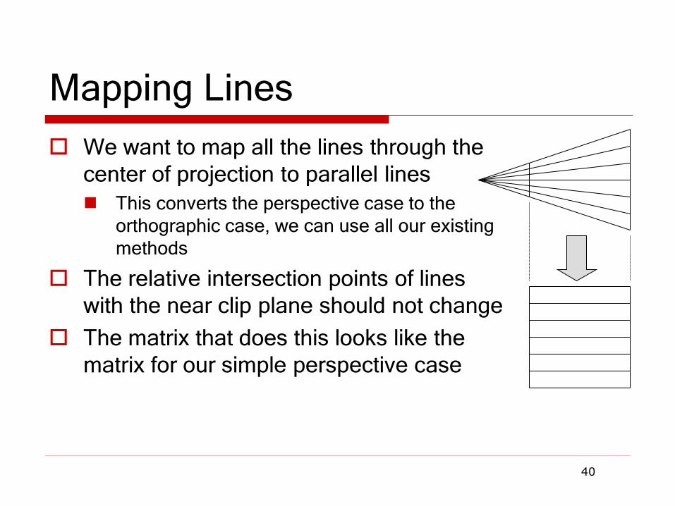
Mapping Lines
We want to map all the lines through the
center of projection to parallel lines
This converts the perspective case to the orthographic case, we can use all our existing methods
The relative intersection points of lines
with the near clip plane should not change
The matrix that does this looks like the
matrix for our simple perspective case
40

General Perspective
41
This matrix leaves points with z=n unchanged
It is just like the simple projection matrix, but it does some extra things to z to map the depth properly
We can multiply a homogenous matrix by any number without changing the final point, so the two matrices above have the same effect
0100
00
000
000
0100
00
0010
0001
nffn
n
n
n
fnfnPM
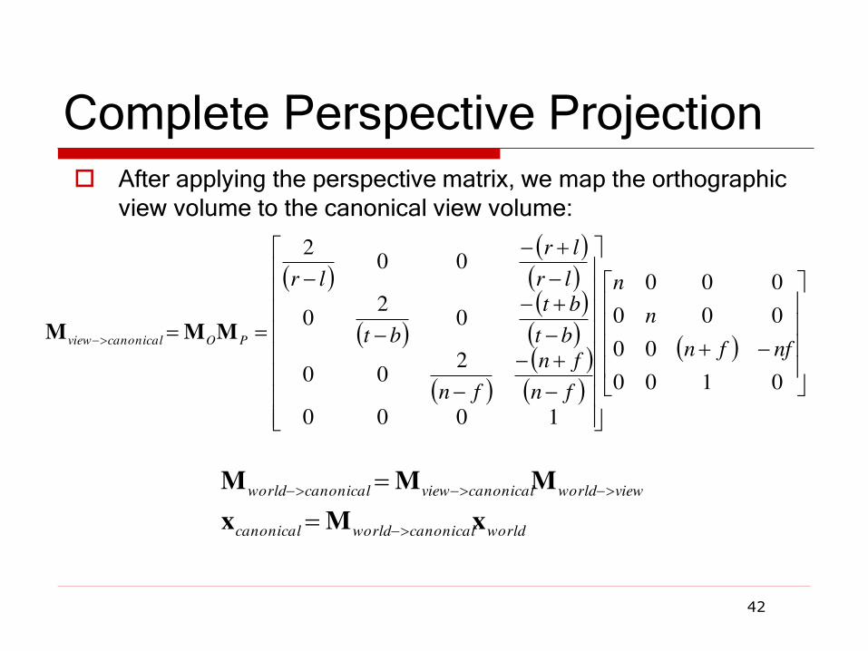
Complete Perspective Projection
42
After applying the perspective matrix, we map the orthographic
view volume to the canonical view volume:
0100
00
000
000
1000
200
02
0
002
nffn
n
n
fn
fn
fn
bt
bt
bt
lr
lr
lr
POcanonicalview MMM
worldcanonicalworldcanonical
viewworldcanonicalviewcanonicalworld
xMx
MMM

Near/Far and Depth Resolution
It may seem sensible to specify a very near clipping plane and a very far clipping plane Sure to contain entire scene
But, a bad idea: OpenGL only has a finite number of bits to store screen depth
Too large a range reduces resolution in depth - wrong thing may be considered “in front”
See Shirley for a more complete explanation
Always place the near plane as far from the viewer as possible, and the far plane as close as possible
43
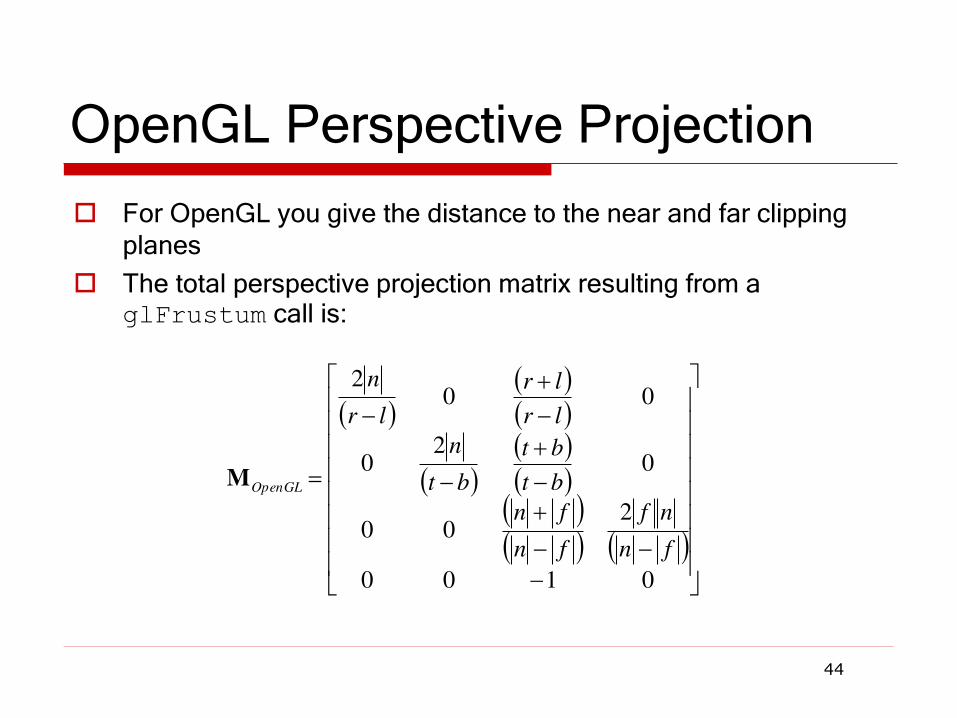
OpenGL Perspective Projection
44
For OpenGL you give the distance to the near and far clipping planes
The total perspective projection matrix resulting from a glFrustum call is:
0100
200
02
0
002
fn
nf
fn
fn
bt
bt
bt
n
lr
lr
lr
n
OpenGLM
Next Time
Clipping
Rasterization
45


![[PPT]2012 Formula SAE - Outboard Suspension - - pdx.eduweb.cecs.pdx.edu/~far/Past Capstone Projects/2012/FSAE... · Web view2012 Formula SAE Outboard Suspension Jose Colin EfeYildirim](https://img.pdfslide.us/doc/110x75/5ae0fda77f8b9a1c248dd435/ppt2012-formula-sae-outboard-suspension-pdx-farpast-capstone-projects2012fsaeweb.jpg)
![arXiv:1309.4218v1 [cond-mat.mtrl-sci] 17 Sep 2013 · PDF file · 2013-09-18Computer simulations of ionic liquids at electrochemical interfaces C. Merlet 1;2, ... sensors, and even](https://img.pdfslide.us/doc/110x75/5aac85ca7f8b9a9c2e8d29b3/arxiv13094218v1-cond-matmtrl-sci-17-sep-2013-simulations-of-ionic-liquids-at.jpg)