Embed Size (px)
Citation preview
Computer-Generated Pen-and-Ink Illustration
Georges Winkenbach, David H. Salesin
Why Pen-and-Ink?
• Can convey information better by omitting extraneous detail (ex, medical & hardware manuals)
• Less storage than photorealistic images, and more easily reproduced and transmitted
• Ideal for outlines, tones and texture.• Blend nicely with text.
Basics of Pen-and-Ink Illustration-Strokes
• A thin stroke can give a washed-out appearance; a thick stroke can detract from the details
• Vary the pen position• Strokes must look natural; the
thickness of a line should vary along its length
• Wavy lines are good
Basics-Tones and texture
• The tone is achieved by a combination of strokes.
• Strokes can convey both tone and texture
• Use equal weight and spacing of lines to create tones
• Correct arrangement of tones among adjacent regions is important
• Use of indication
Basics-Tones and texture
Force tone by enhancing contrast or shadows to disambiguate objects
• The character of strokes is important:– Crisp, straight lines are good for glass– Horizontal surfaces should be hatched with
mostly horizontal lines– Absence of detail indicates glare– Sketchy lines are good for old materials;
careful stippling is good for new material
Basics-Outlines
• Use outlines to convey texture (crisp lines for hard objects)
• Use outlines to bring one object forward in the scene
• Using indication for drawing outlines is important
Computer-generated pen-and-ink illustration
• Two fundamental differences from traditional graphics rendering pipeline:– Dual nature of strokes– Need to combine 2D and 3D
information• Stroke density• 2D adjacent regions• Level of contrast
Non-photorealistic Rendering Pipeline
• Standard pipeline (unchanged)– Model– Assignment of texture (strokes)– Lighting model (phong model)– Visible surface algorithm (BSP)– Shadow algorithm
• Differences from the standard pipeline:– Maintaining 2D spatial subdivision– Rendering of texture and tone (strokes)– Clipping (stroke base)– Outlining (boundary & interior)
Rendering process
• Compute visible surfaces and shadow polygon
• Project polygon to build 2D BSP tree and planar map
• Visible surface is rendered• Procedural texture for each surface• Clip strokes• Draw outlines
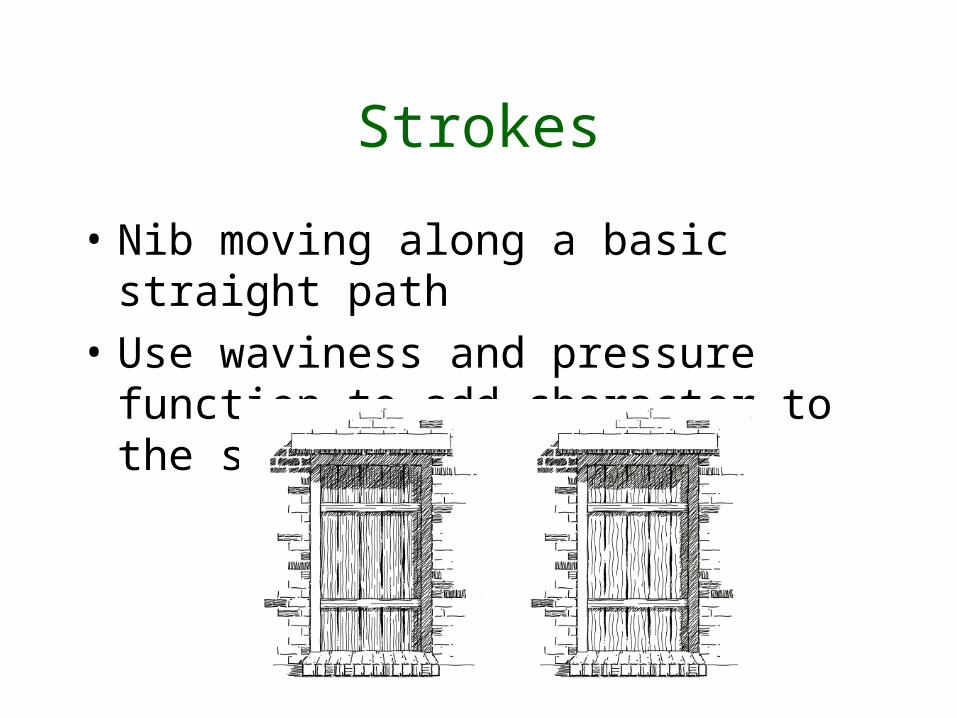
Strokes
• Nib moving along a basic straight path
• Use waviness and pressure function to add character to the strokes
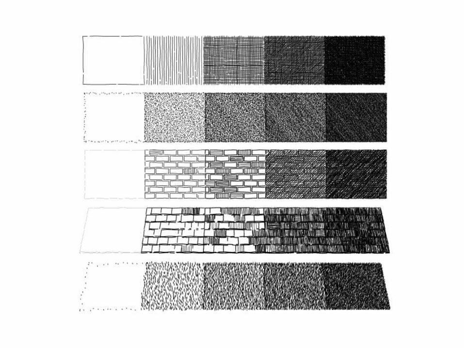
Stroke textures
• Stroke texture – a collection of strokes used to produce texture and tone
• Prioritized stroke texture:– Strokes of highest priority are drawn
first– Continue until the proper tone is
achieved
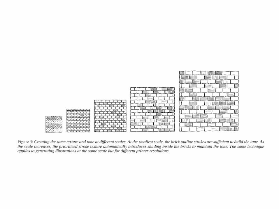
Resolution Dependence
• Existing drawing program do not scale well when printed at different sizes or resolution– Pixel replication yields aliasing artifacts– Drawing same stroke at higher resolution
yields overall lighter illustration– Reduction yields large black mass of
overlapping strokes
• Prioritized stroke textures do not suffer from these problems!!
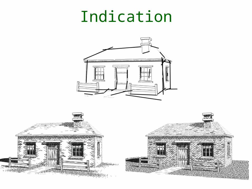
Indication
• Indication lends economy to an illustration
• Suggest texture without drawing every stroke
• Hard to do, paper suggests semi-automated method
• W(x, y) = (a + b*distance((x, y), l))^(-c)
Indication
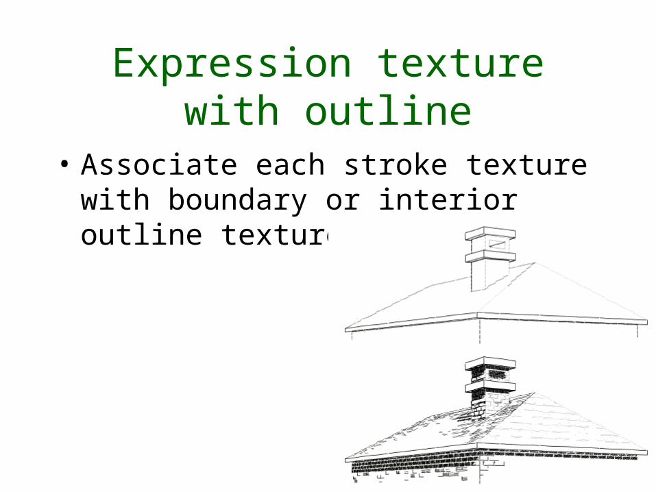
Expression texture with outline
• Associate each stroke texture with boundary or interior outline texture
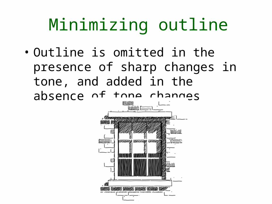
Minimizing outline
• Outline is omitted in the presence of sharp changes in tone, and added in the absence of tone changes
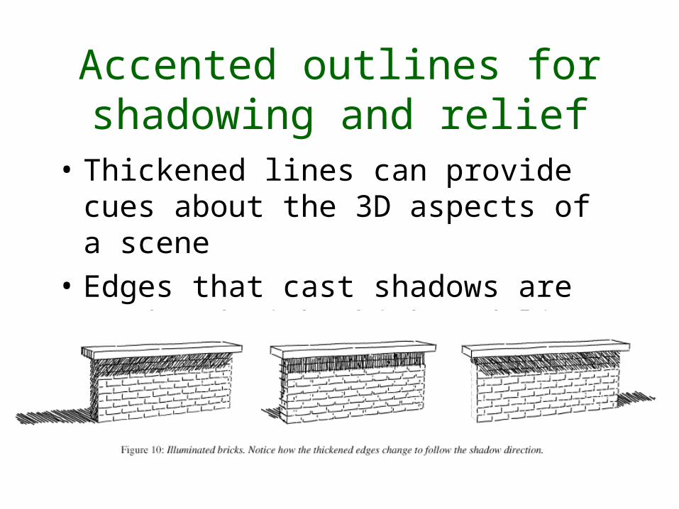
Accented outlines for shadowing and relief
• Thickened lines can provide cues about the 3D aspects of a scene
• Edges that cast shadows are rendered with thickened lines
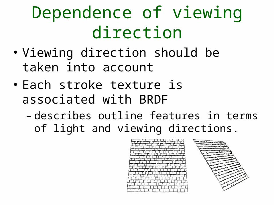
Dependence of viewing direction
• Viewing direction should be taken into account
• Each stroke texture is associated with BRDF– describes outline features in terms of light
and viewing directions.
Conclusion
• Traditional pen-and-ink illustration can be used to communicate visual information effectively
• Showed a large number of these techniques can be incorporated as part of the rendering pipeline
• Introduced prioritized stroke texture to allow resolution-dependent rendering
Robie House

Questions?
Computer-Generated Pen-and-Ink Illustration of
TreesOliver Deussen, Thomas
Strothotte
Presented by Johnny Chang
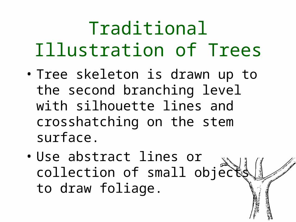
Traditional Illustration of Trees
• Tree skeleton is drawn up to the second branching level with silhouette lines and crosshatching on the stem surface.
• Use abstract lines or collection of small objects to draw foliage.
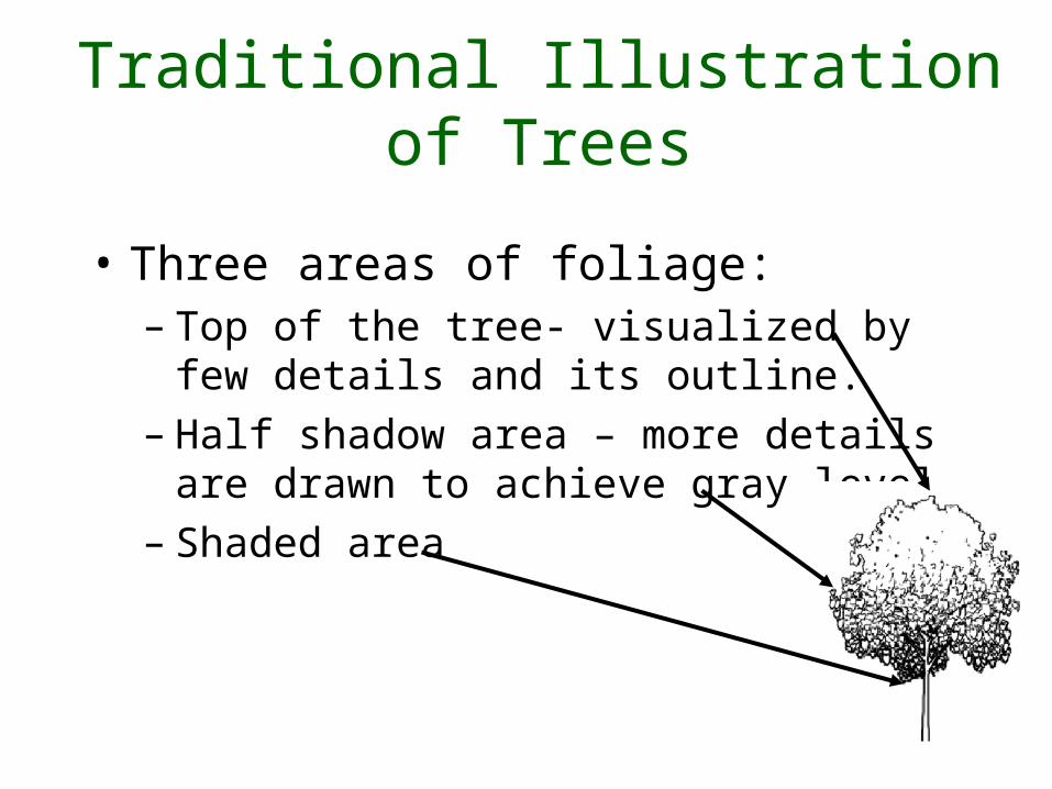
Traditional Illustration of Trees
• Three areas of foliage:– Top of the tree- visualized by few
details and its outline.– Half shadow area – more details are
drawn to achieve gray level.– Shaded area
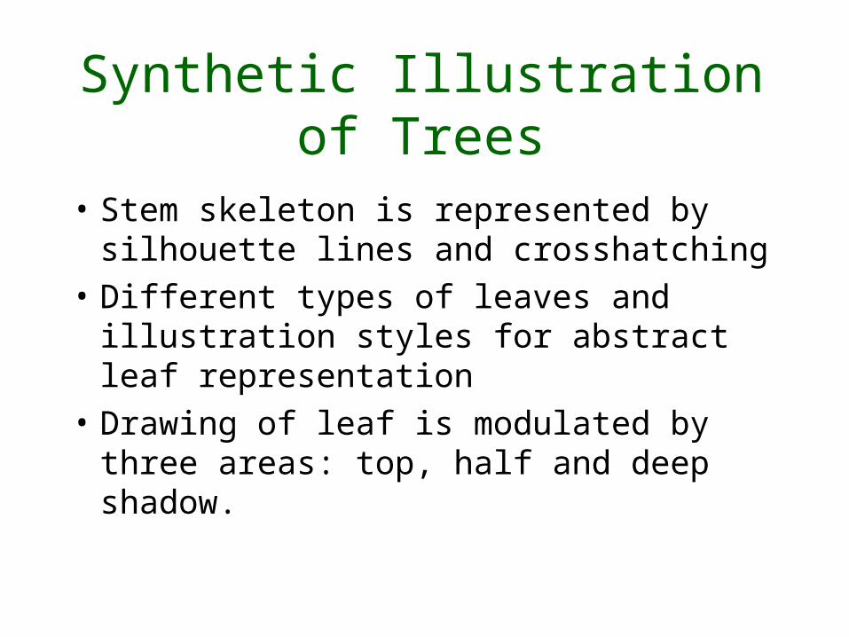
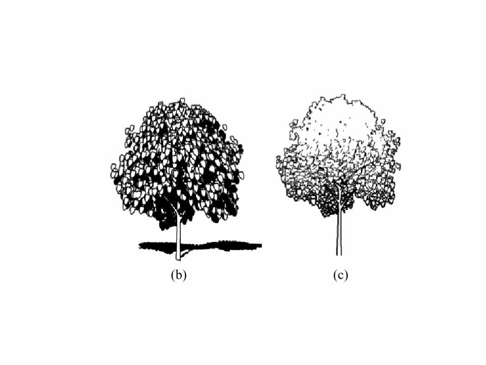
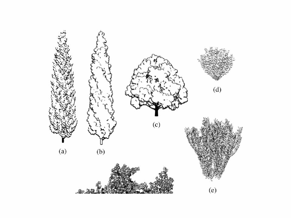
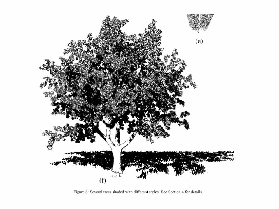
Synthetic Illustration of Trees
• Stem skeleton is represented by silhouette lines and crosshatching
• Different types of leaves and illustration styles for abstract leaf representation
• Drawing of leaf is modulated by three areas: top, half and deep shadow.
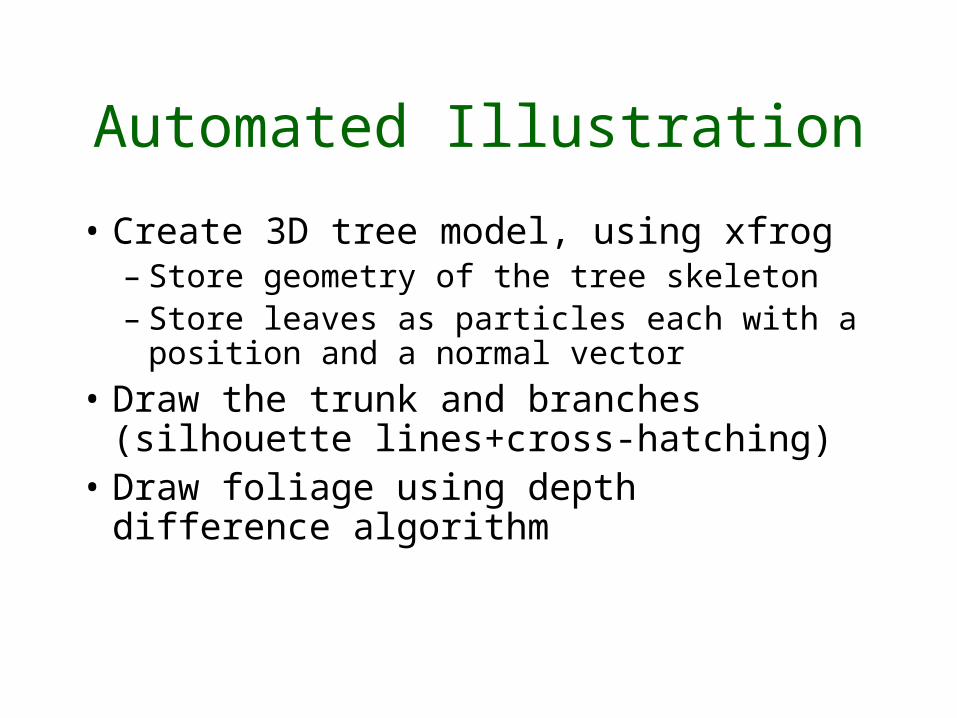
Automated Illustration
• Create 3D tree model, using xfrog– Store geometry of the tree skeleton– Store leaves as particles each with a
position and a normal vector• Draw the trunk and branches
(silhouette lines+cross-hatching)• Draw foliage using depth
difference algorithm
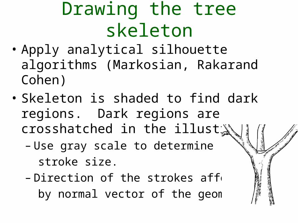
Drawing the tree skeleton
• Apply analytical silhouette algorithms (Markosian, Rakarand Cohen)
• Skeleton is shaded to find dark regions. Dark regions are crosshatched in the illustration.– Use gray scale to determine stroke size.– Direction of the strokes affected by normal vector of the geometry.
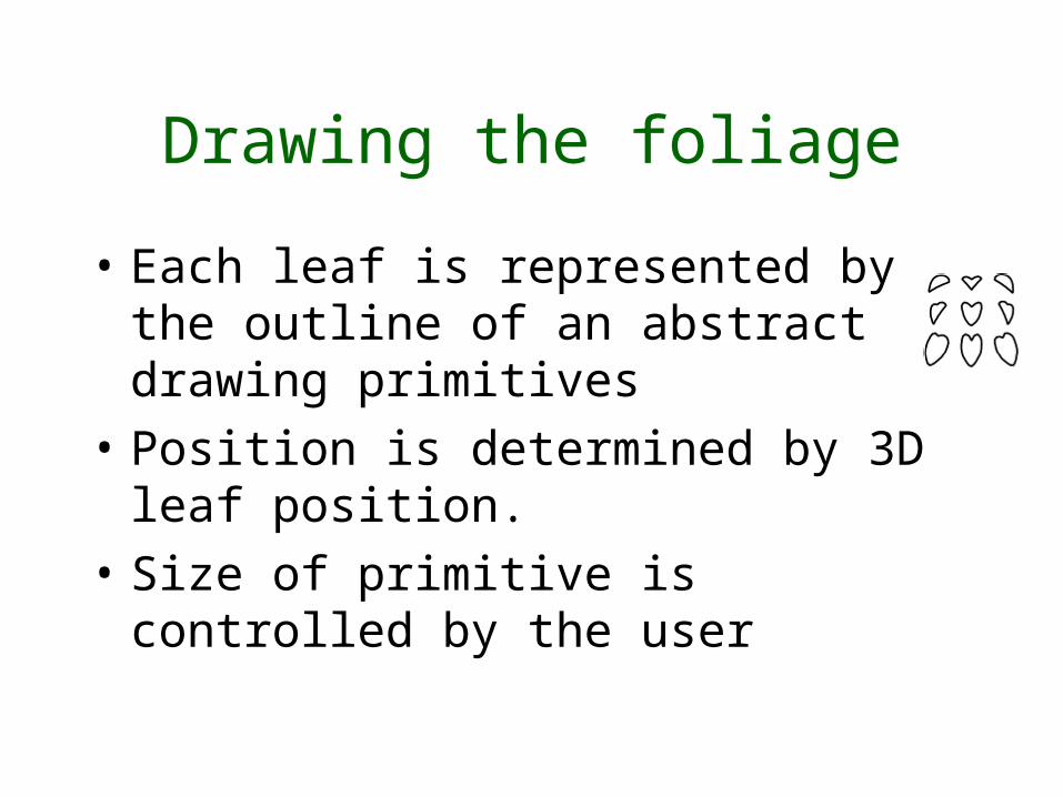
Drawing the foliage
• Each leaf is represented by the outline of an abstract drawing primitives
• Position is determined by 3D leaf position.
• Size of primitive is controlled by the user
Depth Differences
• Use depth-buffer to determine the outline of objects.
• Use zero order derivatives for determining lines
• The outline of a primitive is drawn if depth difference is above a threshold
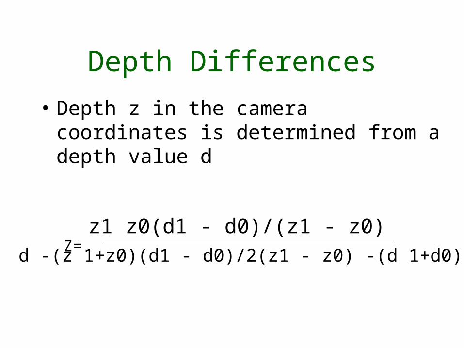
Depth Differences
• Depth z in the camera coordinates is determined from a depth value d
z1 z0(d1 - d0)/(z1 - z0)d -(z 1+z0)(d1 - d0)/2(z1 - z0) -(d 1+d0)/2Z=
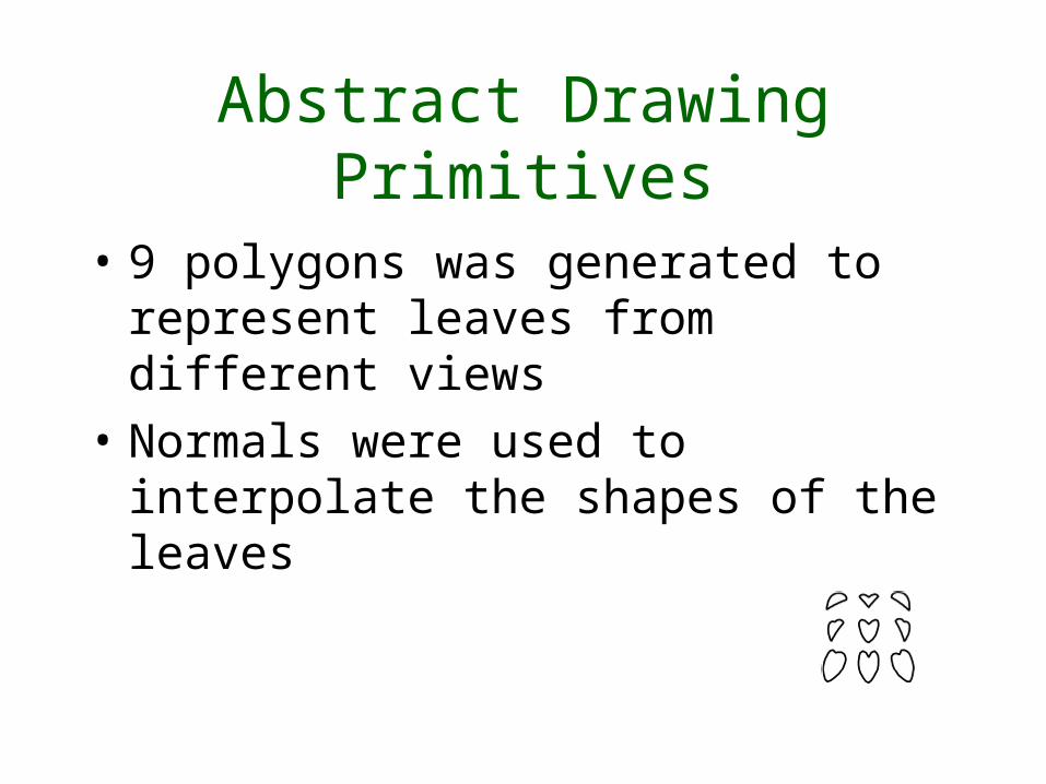
Abstract Drawing Primitives
• 9 polygons was generated to represent leaves from different views
• Normals were used to interpolate the shapes of the leaves
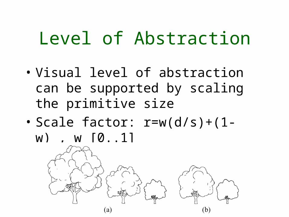
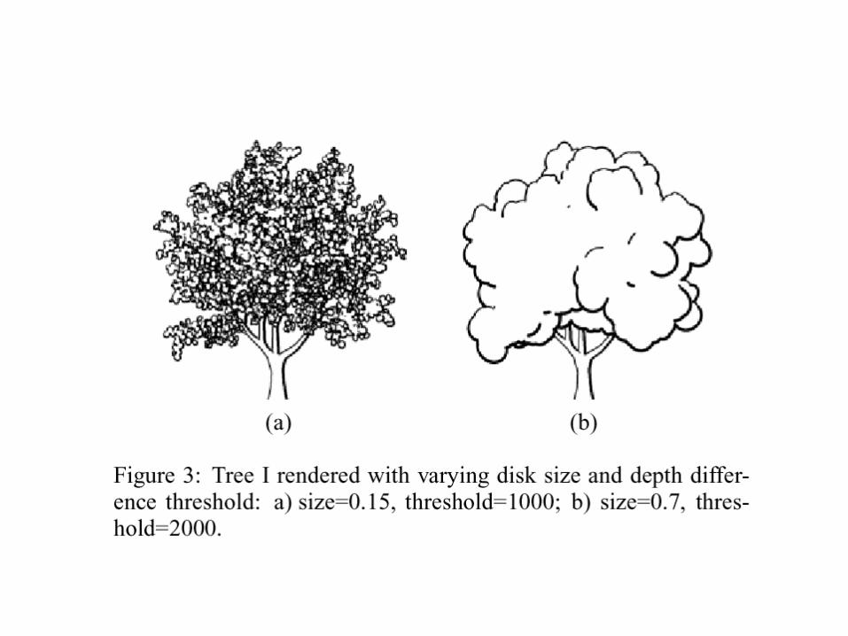
Level of Abstraction
• Visual level of abstraction can be supported by scaling the primitive size
• Scale factor: r=w(d/s)+(1-w) , w [0..1]
Conclusion
• A Framework for pen-and-ink illustration of trees
• Tree skeleton is represented by silhouette lines and crosshatching in dark areas.
• Foliage is drawn using abstract drawing primitives.
• An interpolation scheme to adapt the form of the primitives to the normal vector of the leaves
• Depth differences are used to determine what part of the primitives is drawn.

![Learning Hatching for Pen-and-Ink Illustration of Surfaces€¦ · Learning Hatching for Pen-and-Ink Illustration of Surfaces • 3. and Salesin 1994; 1996]. In these methods, each](https://img.pdfslide.us/doc/110x75/5fa712ff655d5277865cde5d/learning-hatching-for-pen-and-ink-illustration-of-surfaces-learning-hatching-for.jpg)