Embed Size (px)
Citation preview
Eurographics Symposium on Rendering 2003Per Christensen and Daniel Cohen-Or (Editors)
Computer Generated Celtic Design
Matthew Kaplan and Elaine Cohen
University of Utah
AbstractWe present a technique for automating the construction of Celtic knotwork and decorations similar to those inilluminated manuscripts such as the Lindisfarne Gospels. Our method eliminates restrictions imposed by previ-ous methods which limited the class of knots that could be produced correctly by introducing new methods forsmoothing and orienting threads. Additionally, we present techniques for interweaving and attaching images tothe knotwork and techniques to encapsulate knot patterns to simplify the design process. Finally we show howto use such knotwork in 3D and demonstrate a variety of applications including artwork and transforming thedesigns into 3D models for fabrication.
Categories and Subject Descriptors (according to ACM CCS): I.3.0 [Computer Graphics]: General I.3.3 [ComputerGraphics]: Picture/Image Generation I.3.6 [Computer Graphics]: Methodology and Techniques
1. Introduction
Celtic decoration refers to abstract non-imitative artworkoriginating with Celtic tribes dating from about 500 B.C.One of the hallmarks of Celtic art is elaborate knotwork,consisting of entangled threads which maintain a strict over-under alternating pattern between every crossing of thethreads. This knotwork is analogous to closed loops of ropethat cross over and under one another, becoming entangled.The loops of rope are called threads that, when entangled,form the knot.
Although similar artwork has been found in many cul-tures, the specific period of artwork whose style we wish toreproduce is contained in the illuminated manuscripts of theBritish Isles, such as the Lindisfarne Gospels, the Book ofKells, the Book of Durrow and others, created between the7th-9th centuries. It is in these works that Celtic art reachedits zenith, as shown in Figure 16 inset.
At present, Celtic artwork is enjoying a renaissance; itspopularity has manifested itself in design, fine arts, jew-elry, body art, decoration of sculpture, and architecture. Aspointed out by Wong et al. 17 there has been little work inthe area of computer generated ornamentation despite thefact that ornamentation has historically played a critical rolein architecture, decoration and art.
Because of the complexity of Celtic art, creating hand
drawn designs is tedious and time consuming and often re-quires a significant amount of training to do well. Large de-signs are difficult to change and experiment with since localchanges affect the entire knot. Our technique is presented asa tool to design such artwork intuitively, quickly and eas-ily. It augments human talents for design with a computersskill at repetition and drudgery. It offers considerable timesavings over designing such decoration by hand and allowsusers to experiment with global and local changes of bothstyle and form quickly. Automating the fabrication of suchknots for jewelry or decorative use also offers significanttime savings over crafting comparable objects by hand.
Our method offers the following contributions:
• We improve over prior automated methods by allowingthe creation of all possible Celtic knots based on planargraphs (rather than just a limited subset based on grids).Our method demonstrates how to construct such knots au-tomatically, cleanly and without errors.
• We introduce techniques to automatically orient thethreads around any configuration of user defined break-points or graph angles. This is one of the major improve-ments over prior research which severely limited the classof knots which could be correctly produced.
• We present the first method for computers that allows im-ages to be interwoven and connected to the knot.
• We introduce several smoothing techniques to help draw
c© The Eurographics Association 2003.
M. Kaplan and E. Cohen / Computer Generated Celtic Design
the threads more “artistically” and “naturally” and showhow to stylize the threads.
• We show a new method of encapsulation and a back-ground template builder to facilitate the design process.
• We show how to use Celtic knots in 3D by applying ouralgorithms to 2D manifold meshes.
• Finally, we generalize the algorithms to support manufac-turing physical models of the knots created with this pro-gram.
2. Related Work
At some point after the 9th century the techniques used tocreate Celtic art were lost. George Bain 1 reinvented manyof the artistic techniques necessary to create Celtic designs.His son, Iain Bain 2, simplified his father’s methods to besurprisingly algorithmic. His method was based on a tri-gridsystem, which, while constrained by its inability to createknots outside the basic grid pattern, produced beautiful re-sults quickly and easily. Meehan has published a series ofbooks 11, 12, 13, 14 extending I. Bain’s work. Mercat 16 gaverules for manually producing arbitrary knots by interpretinga planar graph as the basis for the construction of the threads.
Mercat 15 and Sloss 19 created programs that allowed usersto create knots by connecting images of thread crossings.Complexity was added to the knots by connecting more im-ages to the knot set. The use of predefined images means thatthese programs are restricted to a limited set of angles andpatterns with which to define threads. This does not repro-duce the general knot algorithm presented by Mercat 16 butrather a simple form of grid knot.
Glassner 5, 6, 7 showed how to compute threads, usingI.Bain’s method (as do 3, 8), that are useful as a guide for cre-ating hand drawn artwork. He concluded that the computeris not useful in automatically creating the knotwork becausea human is able to interpret the thread pattern much moreartistically, though he does show computer generated resultsfor grid patterns. Glassner’s technique required manual ad-justment of curve drawing parameters in complex regionsto produce reasonable results. Recognizing the limitationsof the grid pattern, Glassner allowed the user to deform thegrid shapes in order to output a larger class of knots. Us-ing the deformable grids, Glassner proposed using the outputonly as a guide for hand drawn art. Glassner also showed 3Dknotwork by unfolding the sides of simple objects into 2Dobjects and then refolding after the knot had been computed.This created 3D knots in the shape of the original object, butthe results were not smooth. Moreover, his method seemsdifficult to use for all but the simplest of objects. Severalknot programs such as those by Abbott 0 and Guionnet 9 usethe Mercat technique.
These programs all suffer from a concern raised by Glass-ner: the inability of the computer to choose and draw a threadsmoothly and “artistically”. Previous work on graph basedsystems were all able to correctly determine how to connect
the graph to form threads but were not able to contruct validor smooth threads in any but simple grid cases. The usageof breakpoints (see section 3.6) changes the basic orderingon the graph and is vital to creating visual interest in theknot. In any but the simplest cases, previous programs failedto correctly handle most configurations of breakpoints andwere not able to draw threads correctly around graph config-urations whose angles weren’t explicitly hard coded into thesystem. This is why Glassner proposes using the deformablegrids as only rough guides for hand drawn art. We have de-veloped a general solution to this problem which works forany graph configuration.
Many Celtic knot programs use the basic B-Spline curvemethod to draw the threads, using the crossing locationsas control points for the thread curves. This is unsuitablebecause splines are not able to direct threads correctly us-ing only position information (see section 3.3). Interpolatoryspline methods may also introduce undulation artifacts intothe curve. To account for these problems, an elaborate seriesof extra points are inserted for several predefined graph con-figurations to straighten out the lines and to direct thethreadsaround corners and breakpoints. They fail to correctly ori-ent threads in any situation that does not fall into one of thepredefined cases. This results in an inability either to drawstraight, smooth lines with well formed graphs or to guidethreads correctly around angles or breakpoints that are notpredefined. Furthermore, threads may overlap other threadsin an incorrect manner and exhibit strange discontinuitiesaround sets of breakpoints and irregular graph structures. Weshow solutions to these problems by using a variety of curvesmoothing and directing techniques that work for arbitrarygraphs.
Knot theory is an area of mathematics that deals with thedefinition, structure, equivalence and minimization of knots.Scharein 18 implemented a program for display and manipu-lation of such knots. These results are not directly applicableto Celtic knotwork because the minimization, optimal dis-play and balancing of knots transform the basic visual struc-ture of the knot and the position of its constituent elements,a result that is unacceptable for our purposes.
3. Knotwork
The basic algorithm for artists as presented by Mercat 16 forcreating a Celtic knot is conceptually very simple and wegeneralize it for our purposes:
Following algorithm 1 produces a complete three dimen-sional Celtic knot. When viewed from above, the result canbe displayed in two dimensions. Figure 1 shows an exampleof this process.
3.1. Defining a Graph
The power of the method presented by Mercat is that ev-ery planar graph defines a knot. While methods based on
c© The Eurographics Association 2003.
M. Kaplan and E. Cohen / Computer Generated Celtic Design
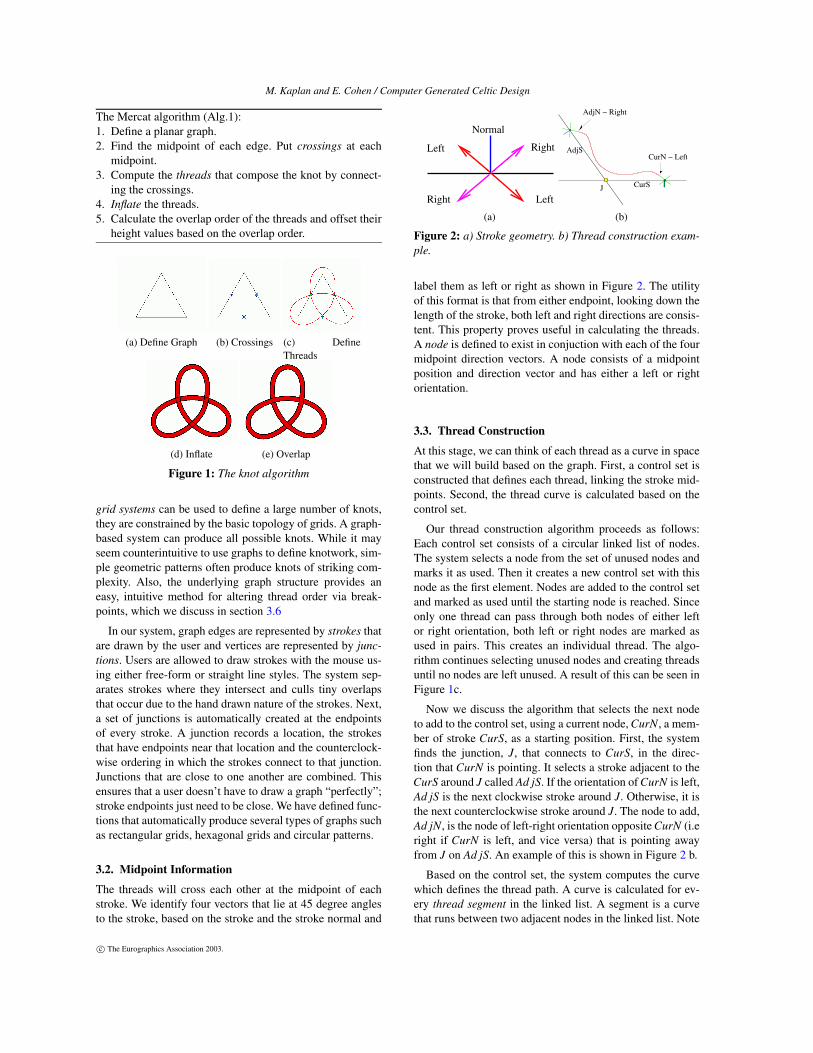
The Mercat algorithm (Alg.1):1. Define a planar graph.2. Find the midpoint of each edge. Put crossings at each
midpoint.3. Compute the threads that compose the knot by connect-
ing the crossings.4. Inflate the threads.5. Calculate the overlap order of the threads and offset their
height values based on the overlap order.
(a) Define Graph (b) Crossings (c) DefineThreads
(d) Inflate (e) Overlap
Figure 1: The knot algorithm
grid systems can be used to define a large number of knots,they are constrained by the basic topology of grids. A graph-based system can produce all possible knots. While it mayseem counterintuitive to use graphs to define knotwork, sim-ple geometric patterns often produce knots of striking com-plexity. Also, the underlying graph structure provides aneasy, intuitive method for altering thread order via break-points, which we discuss in section 3.6
In our system, graph edges are represented by strokes thatare drawn by the user and vertices are represented by junc-tions. Users are allowed to draw strokes with the mouse us-ing either free-form or straight line styles. The system sep-arates strokes where they intersect and culls tiny overlapsthat occur due to the hand drawn nature of the strokes. Next,a set of junctions is automatically created at the endpointsof every stroke. A junction records a location, the strokesthat have endpoints near that location and the counterclock-wise ordering in which the strokes connect to that junction.Junctions that are close to one another are combined. Thisensures that a user doesn’t have to draw a graph “perfectly”;stroke endpoints just need to be close. We have defined func-tions that automatically produce several types of graphs suchas rectangular grids, hexagonal grids and circular patterns.
3.2. Midpoint Information
The threads will cross each other at the midpoint of eachstroke. We identify four vectors that lie at 45 degree anglesto the stroke, based on the stroke and the stroke normal and
����������������������������������������������������������������������������������������������������������������������������������������������������������������������������������������
������������������������
�����������������������������������������������������������������������������������������������������������������������������������������������������������������������������������������������������������������������������������������������������������������������������������������������������������������������������������
�����������������������������������������������������������������������������������������������������������������������������������������������������������������������������������������������������������������������������������������������������������������������������������������������������������������������������������
���������������������������������������������������������������������������������������������������������������������������������������������������������������������������������������������������������������������������������������������������������������������������������������������������������������������������������������������������������������������
���������������������������������������������������������������������������������������������������������������������������������������������������������������������������������������������������������������������������������������������������������������������������������������������������������������������������������������������������������������������
��������������������������������������������������������������������������������������������������������������������������������������������������������������������������
��������������������������������������������������������������������������������������������������������������������������������������������������������������������������
�����������������������������������������������������������������������������������������������������������������������������������������������������������������������������������������������������������������������������������������������������������������������������������������������������������������������������������
�����������������������������������������������������������������������������������������������������������������������������������������������������������������������������������������������������������������������������������������������������������������������������������������������������������������������������������
Normal
Right
LeftRight
Left
(a)
AdjS
J CurS
AdjN − Right
CurN − Left
(b)
Figure 2: a) Stroke geometry. b) Thread construction exam-ple.
label them as left or right as shown in Figure 2. The utilityof this format is that from either endpoint, looking down thelength of the stroke, both left and right directions are consis-tent. This property proves useful in calculating the threads.A node is defined to exist in conjuction with each of the fourmidpoint direction vectors. A node consists of a midpointposition and direction vector and has either a left or rightorientation.
3.3. Thread Construction
At this stage, we can think of each thread as a curve in spacethat we will build based on the graph. First, a control set isconstructed that defines each thread, linking the stroke mid-points. Second, the thread curve is calculated based on thecontrol set.
Our thread construction algorithm proceeds as follows:Each control set consists of a circular linked list of nodes.The system selects a node from the set of unused nodes andmarks it as used. Then it creates a new control set with thisnode as the first element. Nodes are added to the control setand marked as used until the starting node is reached. Sinceonly one thread can pass through both nodes of either leftor right orientation, both left or right nodes are marked asused in pairs. This creates an individual thread. The algo-rithm continues selecting unused nodes and creating threadsuntil no nodes are left unused. A result of this can be seen inFigure 1c.
Now we discuss the algorithm that selects the next nodeto add to the control set, using a current node, CurN, a mem-ber of stroke CurS, as a starting position. First, the systemfinds the junction, J, that connects to CurS, in the direc-tion that CurN is pointing. It selects a stroke adjacent to theCurS around J called Ad jS. If the orientation of CurN is left,Ad jS is the next clockwise stroke around J. Otherwise, it isthe next counterclockwise stroke around J. The node to add,Ad jN, is the node of left-right orientation opposite CurN (i.eright if CurN is left, and vice versa) that is pointing awayfrom J on Ad jS. An example of this is shown in Figure 2 b.
Based on the control set, the system computes the curvewhich defines the thread path. A curve is calculated for ev-ery thread segment in the linked list. A segment is a curvethat runs between two adjacent nodes in the linked list. Note
c© The Eurographics Association 2003.
M. Kaplan and E. Cohen / Computer Generated Celtic Design
(a) (b) (c)
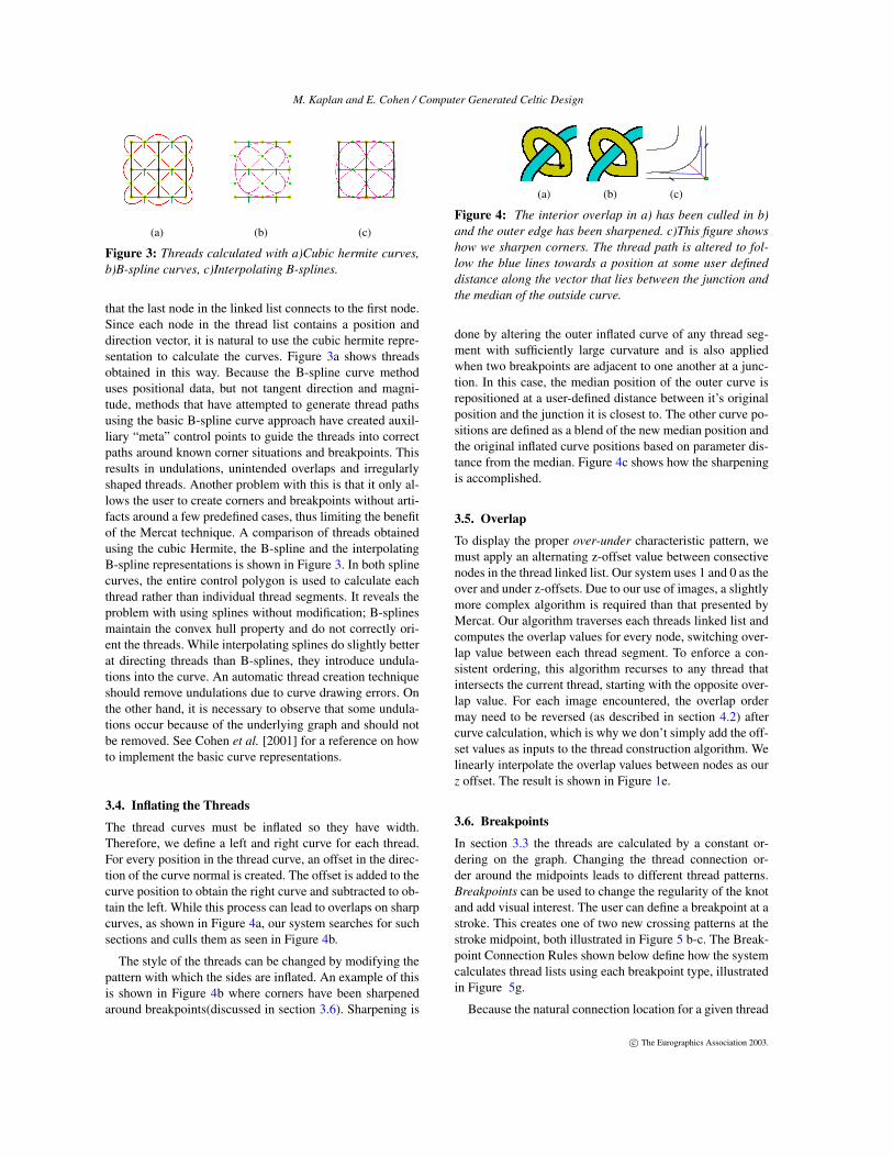
Figure 3: Threads calculated with a)Cubic hermite curves,b)B-spline curves, c)Interpolating B-splines.
that the last node in the linked list connects to the first node.Since each node in the thread list contains a position anddirection vector, it is natural to use the cubic hermite repre-sentation to calculate the curves. Figure 3a shows threadsobtained in this way. Because the B-spline curve methoduses positional data, but not tangent direction and magni-tude, methods that have attempted to generate thread pathsusing the basic B-spline curve approach have created auxil-liary “meta” control points to guide the threads into correctpaths around known corner situations and breakpoints. Thisresults in undulations, unintended overlaps and irregularlyshaped threads. Another problem with this is that it only al-lows the user to create corners and breakpoints without arti-facts around a few predefined cases, thus limiting the benefitof the Mercat technique. A comparison of threads obtainedusing the cubic Hermite, the B-spline and the interpolatingB-spline representations is shown in Figure 3. In both splinecurves, the entire control polygon is used to calculate eachthread rather than individual thread segments. It reveals theproblem with using splines without modification; B-splinesmaintain the convex hull property and do not correctly ori-ent the threads. While interpolating splines do slightly betterat directing threads than B-splines, they introduce undula-tions into the curve. An automatic thread creation techniqueshould remove undulations due to curve drawing errors. Onthe other hand, it is necessary to observe that some undula-tions occur because of the underlying graph and should notbe removed. See Cohen et al. [2001] for a reference on howto implement the basic curve representations.
3.4. Inflating the Threads
The thread curves must be inflated so they have width.Therefore, we define a left and right curve for each thread.For every position in the thread curve, an offset in the direc-tion of the curve normal is created. The offset is added to thecurve position to obtain the right curve and subtracted to ob-tain the left. While this process can lead to overlaps on sharpcurves, as shown in Figure 4a, our system searches for suchsections and culls them as seen in Figure 4b.
The style of the threads can be changed by modifying thepattern with which the sides are inflated. An example of thisis shown in Figure 4b where corners have been sharpenedaround breakpoints(discussed in section 3.6). Sharpening is
(a) (b) (c)
Figure 4: The interior overlap in a) has been culled in b)and the outer edge has been sharpened. c)This figure showshow we sharpen corners. The thread path is altered to fol-low the blue lines towards a position at some user defineddistance along the vector that lies between the junction andthe median of the outside curve.
done by altering the outer inflated curve of any thread seg-ment with sufficiently large curvature and is also appliedwhen two breakpoints are adjacent to one another at a junc-tion. In this case, the median position of the outer curve isrepositioned at a user-defined distance between it’s originalposition and the junction it is closest to. The other curve po-sitions are defined as a blend of the new median position andthe original inflated curve positions based on parameter dis-tance from the median. Figure 4c shows how the sharpeningis accomplished.
3.5. Overlap
To display the proper over-under characteristic pattern, wemust apply an alternating z-offset value between consectivenodes in the thread linked list. Our system uses 1 and 0 as theover and under z-offsets. Due to our use of images, a slightlymore complex algorithm is required than that presented byMercat. Our algorithm traverses each threads linked list andcomputes the overlap values for every node, switching over-lap value between each thread segment. To enforce a con-sistent ordering, this algorithm recurses to any thread thatintersects the current thread, starting with the opposite over-lap value. For each image encountered, the overlap ordermay need to be reversed (as described in section 4.2) aftercurve calculation, which is why we don’t simply add the off-set values as inputs to the thread construction algorithm. Welinearly interpolate the overlap values between nodes as ourz offset. The result is shown in Figure 1e.
3.6. Breakpoints
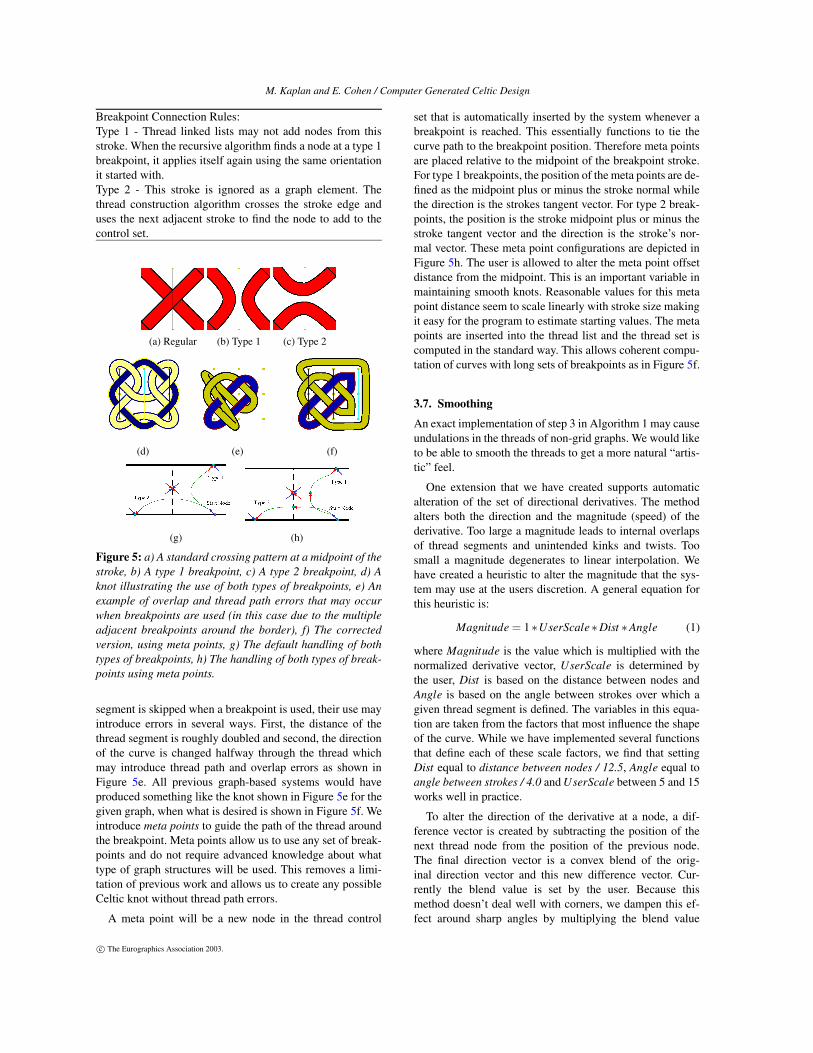
In section 3.3 the threads are calculated by a constant or-dering on the graph. Changing the thread connection or-der around the midpoints leads to different thread patterns.Breakpoints can be used to change the regularity of the knotand add visual interest. The user can define a breakpoint at astroke. This creates one of two new crossing patterns at thestroke midpoint, both illustrated in Figure 5 b-c. The Break-point Connection Rules shown below define how the systemcalculates thread lists using each breakpoint type, illustratedin Figure 5g.
Because the natural connection location for a given thread
c© The Eurographics Association 2003.
M. Kaplan and E. Cohen / Computer Generated Celtic Design
Breakpoint Connection Rules:Type 1 - Thread linked lists may not add nodes from thisstroke. When the recursive algorithm finds a node at a type 1breakpoint, it applies itself again using the same orientationit started with.Type 2 - This stroke is ignored as a graph element. Thethread construction algorithm crosses the stroke edge anduses the next adjacent stroke to find the node to add to thecontrol set.
(a) Regular (b) Type 1 (c) Type 2
(d) (e) (f)
(g) (h)
Figure 5: a) A standard crossing pattern at a midpoint of thestroke, b) A type 1 breakpoint, c) A type 2 breakpoint, d) Aknot illustrating the use of both types of breakpoints, e) Anexample of overlap and thread path errors that may occurwhen breakpoints are used (in this case due to the multipleadjacent breakpoints around the border), f) The correctedversion, using meta points, g) The default handling of bothtypes of breakpoints, h) The handling of both types of break-points using meta points.
segment is skipped when a breakpoint is used, their use mayintroduce errors in several ways. First, the distance of thethread segment is roughly doubled and second, the directionof the curve is changed halfway through the thread whichmay introduce thread path and overlap errors as shown inFigure 5e. All previous graph-based systems would haveproduced something like the knot shown in Figure 5e for thegiven graph, when what is desired is shown in Figure 5f. Weintroduce meta points to guide the path of the thread aroundthe breakpoint. Meta points allow us to use any set of break-points and do not require advanced knowledge about whattype of graph structures will be used. This removes a limi-tation of previous work and allows us to create any possibleCeltic knot without thread path errors.
A meta point will be a new node in the thread control
set that is automatically inserted by the system whenever abreakpoint is reached. This essentially functions to tie thecurve path to the breakpoint position. Therefore meta pointsare placed relative to the midpoint of the breakpoint stroke.For type 1 breakpoints, the position of the meta points are de-fined as the midpoint plus or minus the stroke normal whilethe direction is the strokes tangent vector. For type 2 break-points, the position is the stroke midpoint plus or minus thestroke tangent vector and the direction is the stroke’s nor-mal vector. These meta point configurations are depicted inFigure 5h. The user is allowed to alter the meta point offsetdistance from the midpoint. This is an important variable inmaintaining smooth knots. Reasonable values for this metapoint distance seem to scale linearly with stroke size makingit easy for the program to estimate starting values. The metapoints are inserted into the thread list and the thread set iscomputed in the standard way. This allows coherent compu-tation of curves with long sets of breakpoints as in Figure 5f.
3.7. Smoothing
An exact implementation of step 3 in Algorithm 1 may causeundulations in the threads of non-grid graphs. We would liketo be able to smooth the threads to get a more natural “artis-tic” feel.
One extension that we have created supports automaticalteration of the set of directional derivatives. The methodalters both the direction and the magnitude (speed) of thederivative. Too large a magnitude leads to internal overlapsof thread segments and unintended kinks and twists. Toosmall a magnitude degenerates to linear interpolation. Wehave created a heuristic to alter the magnitude that the sys-tem may use at the users discretion. A general equation forthis heuristic is:
Magnitude = 1∗UserScale∗Dist ∗Angle (1)
where Magnitude is the value which is multiplied with thenormalized derivative vector, UserScale is determined bythe user, Dist is based on the distance between nodes andAngle is based on the angle between strokes over which agiven thread segment is defined. The variables in this equa-tion are taken from the factors that most influence the shapeof the curve. While we have implemented several functionsthat define each of these scale factors, we find that settingDist equal to distance between nodes / 12.5, Angle equal toangle between strokes / 4.0 and UserScale between 5 and 15works well in practice.
To alter the direction of the derivative at a node, a dif-ference vector is created by subtracting the position of thenext thread node from the position of the previous node.The final direction vector is a convex blend of the orig-inal direction vector and this new difference vector. Cur-rently the blend value is set by the user. Because thismethod doesn’t deal well with corners, we dampen this ef-fect around sharp angles by multiplying the blend value
c© The Eurographics Association 2003.
M. Kaplan and E. Cohen / Computer Generated Celtic Design
(a) (b)
Figure 6: The circular graph for this knot is ill formed whichleads to the kinks evident in a). In b) the knot has beensmoothed by altering the cubic hermite derivatives.
(a) (b) (c) (d)
Figure 7: Alternate knot display styles.
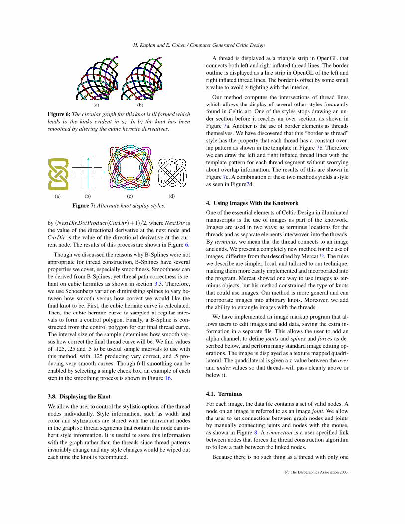
by (NextDir.DotProduct(CurDir)+1)/2, where NextDir isthe value of the directional derivative at the next node andCurDir is the value of the directional derivative at the cur-rent node. The results of this process are shown in Figure 6.
Though we discussed the reasons why B-Splines were notappropriate for thread construction, B-Splines have severalproperties we covet, especially smoothness. Smoothness canbe derived from B-Splines, yet thread path correctness is re-liant on cubic hermites as shown in section 3.3. Therefore,we use Schoenberg variation diminishing splines to vary be-tween how smooth versus how correct we would like thefinal knot to be. First, the cubic hermite curve is calculated.Then, the cubic hermite curve is sampled at regular inter-vals to form a control polygon. Finally, a B-Spline is con-structed from the control polygon for our final thread curve.The interval size of the sample determines how smooth ver-sus how correct the final thread curve will be. We find valuesof .125, .25 and .5 to be useful sample intervals to use withthis method, with .125 producing very correct, and .5 pro-ducing very smooth curves. Though full smoothing can beenabled by selecting a single check box, an example of eachstep in the smoothing process is shown in Figure 16.
3.8. Displaying the Knot
We allow the user to control the stylistic options of the threadnodes individually. Style information, such as width andcolor and stylizations are stored with the individual nodesin the graph so thread segments that contain the node can in-herit style information. It is useful to store this informationwith the graph rather than the threads since thread patternsinvariably change and any style changes would be wiped outeach time the knot is recomputed.
A thread is displayed as a triangle strip in OpenGL thatconnects both left and right inflated thread lines. The borderoutline is displayed as a line strip in OpenGL of the left andright inflated thread lines. The border is offset by some smallz value to avoid z-fighting with the interior.
Our method computes the intersections of thread lineswhich allows the display of several other styles frequentlyfound in Celtic art. One of the styles stops drawing an un-der section before it reaches an over section, as shown inFigure 7a. Another is the use of border elements as threadsthemselves. We have discovered that this “border as thread”style has the property that each thread has a constant over-lap pattern as shown in the template in Figure 7b. Thereforewe can draw the left and right inflated thread lines with thetemplate pattern for each thread segment without worryingabout overlap information. The results of this are shown inFigure 7c. A combination of these two methods yields a styleas seen in Figure7d.
4. Using Images With the Knotwork
One of the essential elements of Celtic Design in illuminatedmanuscripts is the use of images as part of the knotwork.Images are used in two ways: as terminus locations for thethreads and as separate elements interwoven into the threads.By terminus, we mean that the thread connects to an imageand ends. We present a completely new method for the use ofimages, differing from that described by Mercat 16. The ruleswe describe are simpler, local, and tailored to our technique,making them more easily implemented and incorporated intothe program. Mercat showed one way to use images as ter-minus objects, but his method constrained the type of knotsthat could use images. Our method is more general and canincorporate images into arbitrary knots. Moreover, we addthe ability to entangle images with the threads.
We have implemented an image markup program that al-lows users to edit images and add data, saving the extra in-formation in a separate file. This allows the user to add analpha channel, to define joints and spines and forces as de-scribed below, and perform many standard image editing op-erations. The image is displayed as a texture mapped quadri-lateral. The quadrilateral is given a z-value between the overand under values so that threads will pass cleanly above orbelow it.
4.1. Terminus
For each image, the data file contains a set of valid nodes. Anode on an image is referred to as an image joint. We allowthe user to set connections between graph nodes and jointsby manually connecting joints and nodes with the mouse,as shown in Figure 8. A connection is a user specified linkbetween nodes that forces the thread construction algorithmto follow a path between the linked nodes.
Because there is no such thing as a thread with only one
c© The Eurographics Association 2003.
M. Kaplan and E. Cohen / Computer Generated Celtic Design
(a) (b) Joints (c) Spines
(d) (e) (f)
(g) (h) (i)
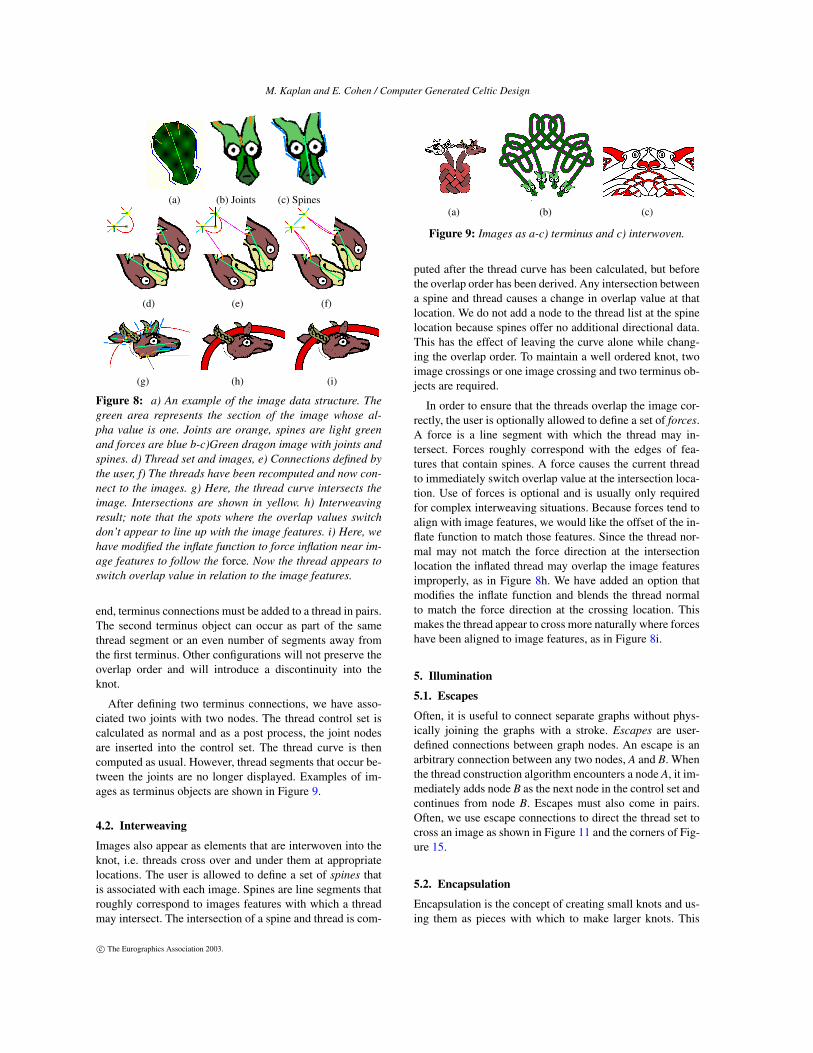
Figure 8: a) An example of the image data structure. Thegreen area represents the section of the image whose al-pha value is one. Joints are orange, spines are light greenand forces are blue b-c)Green dragon image with joints andspines. d) Thread set and images, e) Connections defined bythe user, f) The threads have been recomputed and now con-nect to the images. g) Here, the thread curve intersects theimage. Intersections are shown in yellow. h) Interweavingresult; note that the spots where the overlap values switchdon’t appear to line up with the image features. i) Here, wehave modified the inflate function to force inflation near im-age features to follow the force. Now the thread appears toswitch overlap value in relation to the image features.
end, terminus connections must be added to a thread in pairs.The second terminus object can occur as part of the samethread segment or an even number of segments away fromthe first terminus. Other configurations will not preserve theoverlap order and will introduce a discontinuity into theknot.
After defining two terminus connections, we have asso-ciated two joints with two nodes. The thread control set iscalculated as normal and as a post process, the joint nodesare inserted into the control set. The thread curve is thencomputed as usual. However, thread segments that occur be-tween the joints are no longer displayed. Examples of im-ages as terminus objects are shown in Figure 9.
4.2. Interweaving
Images also appear as elements that are interwoven into theknot, i.e. threads cross over and under them at appropriatelocations. The user is allowed to define a set of spines thatis associated with each image. Spines are line segments thatroughly correspond to images features with which a threadmay intersect. The intersection of a spine and thread is com-
(a) (b) (c)
Figure 9: Images as a-c) terminus and c) interwoven.
puted after the thread curve has been calculated, but beforethe overlap order has been derived. Any intersection betweena spine and thread causes a change in overlap value at thatlocation. We do not add a node to the thread list at the spinelocation because spines offer no additional directional data.This has the effect of leaving the curve alone while chang-ing the overlap order. To maintain a well ordered knot, twoimage crossings or one image crossing and two terminus ob-jects are required.
In order to ensure that the threads overlap the image cor-rectly, the user is optionally allowed to define a set of forces.A force is a line segment with which the thread may in-tersect. Forces roughly correspond with the edges of fea-tures that contain spines. A force causes the current threadto immediately switch overlap value at the intersection loca-tion. Use of forces is optional and is usually only requiredfor complex interweaving situations. Because forces tend toalign with image features, we would like the offset of the in-flate function to match those features. Since the thread nor-mal may not match the force direction at the intersectionlocation the inflated thread may overlap the image featuresimproperly, as in Figure 8h. We have added an option thatmodifies the inflate function and blends the thread normalto match the force direction at the crossing location. Thismakes the thread appear to cross more naturally where forceshave been aligned to image features, as in Figure 8i.
5. Illumination
5.1. Escapes
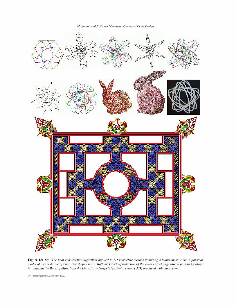
Often, it is useful to connect separate graphs without phys-ically joining the graphs with a stroke. Escapes are user-defined connections between graph nodes. An escape is anarbitrary connection between any two nodes, A and B. Whenthe thread construction algorithm encounters a node A, it im-mediately adds node B as the next node in the control set andcontinues from node B. Escapes must also come in pairs.Often, we use escape connections to direct the thread set tocross an image as shown in Figure 11 and the corners of Fig-ure 15.
5.2. Encapsulation
Encapsulation is the concept of creating small knots and us-ing them as pieces with which to make larger knots. This
c© The Eurographics Association 2003.
M. Kaplan and E. Cohen / Computer Generated Celtic Design
(a) (b) (c)
(d) (e) (f)
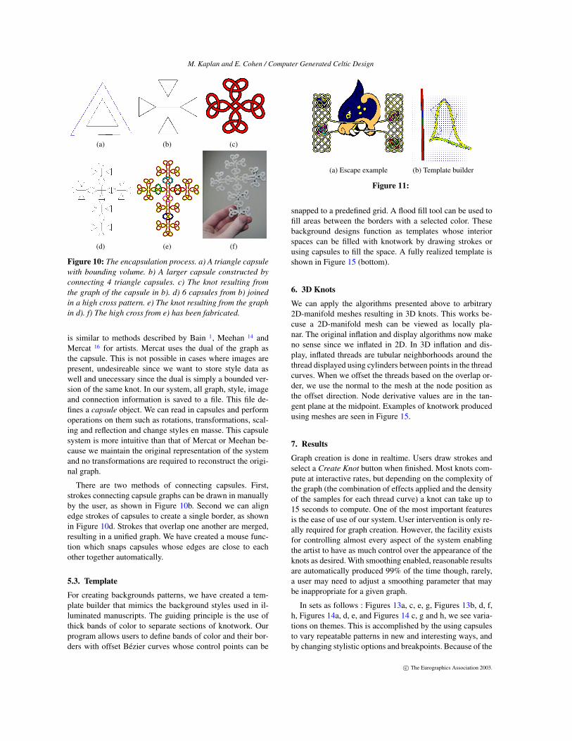
Figure 10: The encapsulation process. a) A triangle capsulewith bounding volume. b) A larger capsule constructed byconnecting 4 triangle capsules. c) The knot resulting fromthe graph of the capsule in b). d) 6 capsules from b) joinedin a high cross pattern. e) The knot resulting from the graphin d). f) The high cross from e) has been fabricated.
is similar to methods described by Bain 1, Meehan 14 andMercat 16 for artists. Mercat uses the dual of the graph asthe capsule. This is not possible in cases where images arepresent, undesireable since we want to store style data aswell and unecessary since the dual is simply a bounded ver-sion of the same knot. In our system, all graph, style, imageand connection information is saved to a file. This file de-fines a capsule object. We can read in capsules and performoperations on them such as rotations, transformations, scal-ing and reflection and change styles en masse. This capsulesystem is more intuitive than that of Mercat or Meehan be-cause we maintain the original representation of the systemand no transformations are required to reconstruct the origi-nal graph.
There are two methods of connecting capsules. First,strokes connecting capsule graphs can be drawn in manuallyby the user, as shown in Figure 10b. Second we can alignedge strokes of capsules to create a single border, as shownin Figure 10d. Strokes that overlap one another are merged,resulting in a unified graph. We have created a mouse func-tion which snaps capsules whose edges are close to eachother together automatically.
5.3. Template
For creating backgrounds patterns, we have created a tem-plate builder that mimics the background styles used in il-luminated manuscripts. The guiding principle is the use ofthick bands of color to separate sections of knotwork. Ourprogram allows users to define bands of color and their bor-ders with offset Bézier curves whose control points can be
(a) Escape example (b) Template builder
Figure 11:
snapped to a predefined grid. A flood fill tool can be used tofill areas between the borders with a selected color. Thesebackground designs function as templates whose interiorspaces can be filled with knotwork by drawing strokes orusing capsules to fill the space. A fully realized template isshown in Figure 15 (bottom).
6. 3D Knots
We can apply the algorithms presented above to arbitrary2D-manifold meshes resulting in 3D knots. This works be-cuse a 2D-manifold mesh can be viewed as locally pla-nar. The original inflation and display algorithms now makeno sense since we inflated in 2D. In 3D inflation and dis-play, inflated threads are tubular neighborhoods around thethread displayed using cylinders between points in the threadcurves. When we offset the threads based on the overlap or-der, we use the normal to the mesh at the node position asthe offset direction. Node derivative values are in the tan-gent plane at the midpoint. Examples of knotwork producedusing meshes are seen in Figure 15.
7. Results
Graph creation is done in realtime. Users draw strokes andselect a Create Knot button when finished. Most knots com-pute at interactive rates, but depending on the complexity ofthe graph (the combination of effects applied and the densityof the samples for each thread curve) a knot can take up to15 seconds to compute. One of the most important featuresis the ease of use of our system. User intervention is only re-ally required for graph creation. However, the facility existsfor controlling almost every aspect of the system enablingthe artist to have as much control over the appearance of theknots as desired. With smoothing enabled, reasonable resultsare automatically produced 99% of the time though, rarely,a user may need to adjust a smoothing parameter that maybe inappropriate for a given graph.
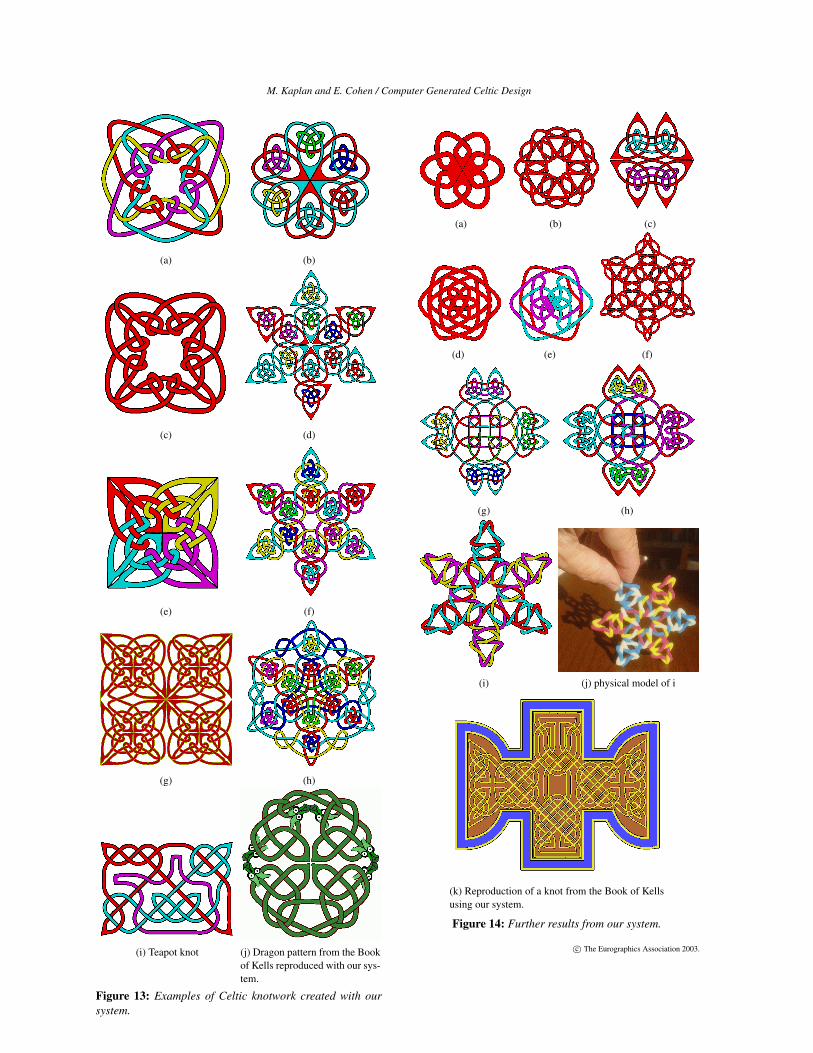
In sets as follows : Figures 13a, c, e, g, Figures 13b, d, f,h, Figures 14a, d, e, and Figures 14 c, g and h, we see varia-tions on themes. This is accomplished by the using capsulesto vary repeatable patterns in new and interesting ways, andby changing stylistic options and breakpoints. Because of the
c© The Eurographics Association 2003.
M. Kaplan and E. Cohen / Computer Generated Celtic Design
utility and ease of use of encapsulation most of these designstook between 1 and 2 minutes to produce. Figure 13i showsa teapot shape embedded in a knot as a thread, demonstrat-ing how logos and other symbols may be incorporated intoCeltic knots produced with our system.
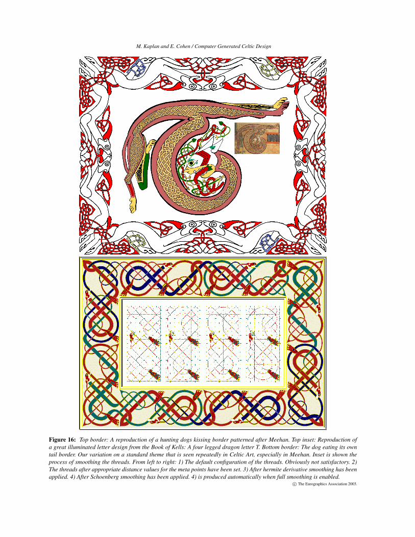
The reproductions of art from the Book of Kells (Fig-ures 16 top, inset, 13j, 14j ) and the Lindisfarne Gospels(Figure 15) using our system validate the utility of our tech-niques for reproducing the artwork of the masters of Celticillumination. These examples mark the first time a com-puter has accurately reproduced the knotwork from full car-pet pages and illuminated letters from the great works ofthe Celtic illuminated manuscripts. All of the techniquespresented were required to create these images and noprior knotwork creation program could have produced them.These results are important because it shows that not onlycan our system reproduce the complexity of the originalworks, but we can create new works with the same style andbeauty of the originals. Moreover, we can do it much morequickly and can experiment with alternate designs, stylesand patterns with almost no additional effort. The only clas-sical patterns we have not been able to reproduce are thosethat contain images which interweave with each other whichis a problem we have not addressed here. The upper bor-der in Figure 16 took about a half hour to make. The im-ages took about 5-10 minutes to mark with an alpha channeland relevant information. Design of such a work proceeds asfollows: filling the empty spaces in the images with graphs,making connections from the graphs to the images and fi-nally replicating the two capsules (one for each dog image)and arranging the capsules in a border pattern. The centralT pattern in the illuminated letter in Figure 16 was drawnfreehand in about 5-10 minutes. Style changes to these de-signs are quick as regions can be selected with the mouseand changes applied en masse.
The zoomorphic borders shown in Figure 16 are after thestyle of Meehan 14 which in turn take their inspiration andfigures from the Book of Kells. Inset (at bottom) is an exam-ple of the smoothing process which is vital to achieving vi-sually pleasing results. The smoothest knot is automaticallyproduced when full smoothing is enabled yet we show thesteps for instructional purposes. The lower border demon-strates thread width variation to full advantage.
In Figure 12a, a user has designed body art using our pro-gram and a temporary tattoo has been applied with henna.In Figure 12b, our system has created a 3 dimensional knotmodel for a CAD program. The CAD program has definedcircular tubes of revolution around the piecewise cubic her-mite thread curves. Using the CAD model as an input, aphysical 3D model was fabricated using a Stratasys rapidprototyping system, as shown in Figure 12c and Figure 10f.A user can quickly test many designs on the computer, thencreate physical results for jewelry or ornamentation automat-ically, a process that used to be extremely time consuming.
(a) (b) (c)
Figure 12: Uniform design: a) A tattoo design, b) CADmodel and c) jewelry created by fabricating the CAD model
8. Conclusion and Future Work
We have presented techniques for automating the construc-tion of Celtic knotwork and for creating large complex de-signs with such knotwork. We have introduced novel orien-tation and smoothing techniques which allow us to computeand display knots in both 2D and 3D, eliminating restrictionsof prior work in this area. We have shown how to incorporateimages into Celtic knots both as terminus objects and inter-woven elements. We have introduced a new method of en-capsulation to facilitate the design process and have shownhow to construct background templates in the style of theancient manuscripts. Further, we have shown how to auto-matically fabricate physical models from such knots.
In the future, automatic knot generation using au-tonomous capsule placement might be a useful feature toexplore. Because of the connection to woven materials (thebunny knot in Figure 15 appears crotcheted), cloth simula-tion and rendering seem a natural extension. Ultimately, weview this system as an artistic playground, where artists, de-signers and novices alike may quickly and easily explore thecreation of advanced Celtic knotwork designs.
9. AcknowledgementsThis work was supported in part by ARO (DAAD19-01-1-0013) and NSF (EIA0121533).All opinions, findings, conclusions or recommendations expressed in this document arethose of the author and do not necessarily reflect the views of the sponsoring agencies.
References0. ABBOTT, S. Knots3d. Computer Program, www.abbott.demon.co.uk/knots.html. 21. BAIN, G. 1951. Celtic Art, The Methods of Construction. William MacLellan and Co.,
Glasgow,Scotland. 2, 82. BAIN, I. 1966. Celtic Knotwork. Sterling Publishing Co. 23. BROWNE, C. 1998 Font Decoration by Automatic Mesh Fitting. Proceedings of EP-
RIDT ’98, 23-43 24. E. COHEN, R.F. RIESENFELD, G. E. 2001. Geometric Modeling With Splines. AK
Peters.5. GLASSNER, A. 2002. Andrew Glassner’s Other Notebook. AK Peters. 26. GLASSNER, A. November/December 1999. Andrew glassner’s notebook : Celtic knot-
work, part 2. IEEE Computer Graphics and Applications, 78–84. 27. GLASSNER, A. September/October 1999. Andrew glassner’s notebook : Celtic knot-
work, part 1. IEEE Computer Graphics and Applications, 78–84. 28. GODFREY, R. Celtic knots designer. Computer Program, www.celticdesigner.com. 29. GUIONNET, T. Les noeuds celtiques. Computer Program. 211. MEEHAN, A. 1991. Celtic Design: A Beginners Manual. Thames and Hudson. 212. MEEHAN, A. 1991. Celtic Design: Knotwork, The Secret Method of the Scribes.
Thames and Hudson. 213. MEEHAN, A. 1992. Celtic Design: Illuminated Letters. Thames and Hudson. 214. MEEHAN, A. 1999. Celtic Borders. Thames and Hudson. 2, 8, 915. MERCAT, C. Celtic knots. Computer program. 216. MERCAT, C. 1997. Les entrelacs des enluminures celtes. Dossier Pour La Science,
No.15. 2, 6, 817. MICHAEL T. WONG, DOUGLAS E.ZONGKER, D. S. 1998. Computer generated floral
ornament. Proceedings of SIGGRAPH 98 (August), 423–432. 118. SCHAREIN, R. 1998. Interactive Topological Drawing. PhD thesis, University of
British Columbia. 219. SLOSS, A. 1995. How to Draw Celtic Knotwork: A Practical Handbook. Brockhampton
Press. 2
c© The Eurographics Association 2003.
M. Kaplan and E. Cohen / Computer Generated Celtic Design
(a) (b)
(c) (d)
(e) (f)
(g) (h)
(i) Teapot knot (j) Dragon pattern from the Bookof Kells reproduced with our sys-tem.
Figure 13: Examples of Celtic knotwork created with oursystem.
(a) (b) (c)
(d) (e) (f)
(g) (h)
(i) (j) physical model of i
(k) Reproduction of a knot from the Book of Kellsusing our system.
Figure 14: Further results from our system.
c© The Eurographics Association 2003.
M. Kaplan and E. Cohen / Computer Generated Celtic Design
Figure 15: Top: The knot construction algorithm applied to 3D geometric meshes including a bunny mesh. Also, a physicalmodel of a knot derived from a star shaped mesh. Bottom: Exact reproduction of the great carpet page thread pattern topologyintroducing the Book of Mark from the Lindisfarne Gospels (ca. 6-7th century AD) produced with our system.
c© The Eurographics Association 2003.
M. Kaplan and E. Cohen / Computer Generated Celtic Design
Figure 16: Top border: A reproduction of a hunting dogs kissing border patterned after Meehan. Top inset: Reproduction ofa great illuminated letter design from the Book of Kells: A four legged dragon letter T. Bottom border: The dog eating its owntail border. Our variation on a standard theme that is seen repeatedly in Celtic Art, especially in Meehan. Inset is shown theprocess of smoothing the threads. From left to right: 1) The default configuration of the threads. Obviously not satisfactory. 2)The threads after appropriate distance values for the meta points have been set. 3) After hermite derivative smoothing has beenapplied. 4) After Schoenberg smoothing has been applied. 4) is produced automatically when full smoothing is enabled.
c© The Eurographics Association 2003.


![To Stylize or not to Stylize? The Effect of Shape and …...2012], the possible adaptation of the society to cartoon faces [Chen et al. 2010], the viewers’ level of expertise in](https://img.pdfslide.us/doc/110x75/5f88c7097ff7845efe2eecf4/to-stylize-or-not-to-stylize-the-effect-of-shape-and-2012-the-possible-adaptation.jpg)